

Page 1

PARTS
MANUAL
Models
DY23-2 / DY27-2
ENGINE
PUB-EP5754A
Rev. 07/00
Page 2

940 Lively Blvd. Wood Dale, IL 60191 Phone: 630-350-8200 Fax: 630-350-8212
e-mail: sales@robinamerica.com • www.robinamerica.com
© Copyright 2000 Robin America, Inc.
Page 3
HOW TO USE THIS MANUAL
Robin engines are identified by MODEL, SPECIFICATION, and CODE NUMBER. For each
model there may be many different versions called specifications. Each specification will be
unique in some way. The difference may only be the paint color or it may have a different
type of PTO or some other significant difference.
In order the identify the correct service part number, it is important to confirm the specification and code numbers for your engine. The specification and code number together are
know as the PRODUCT NUMBER.
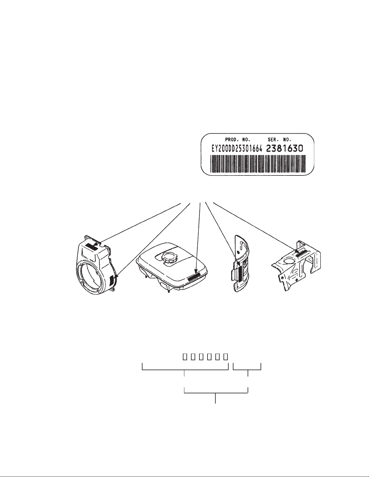
All Robin 4 cycle engines have a Product Number label similar to the label illustrated below.
PRODUCT NUMBER LABEL
PRODUCT NUMBER LABEL LOCATIONS
The Product Number Label has a 15 digit alphanumeric string that consists of the
SPECIFICATION (SPEC) number (11 digits) and the CODE number (4 digits). Please
note the illustration below:
D Y 2 3 2
SPEC NO. (11 digits) CODE NO. (4 digits)
PRODUCT NO. (15 digits)
- 3 - '00-07
X X X X
Page 4
MANUAL LAYOUT
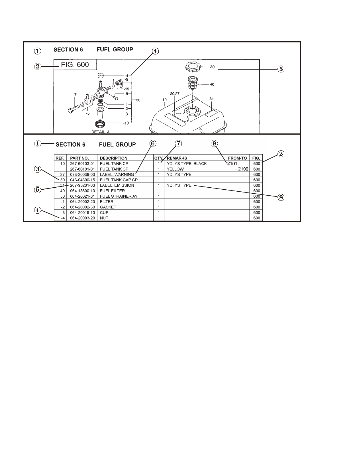
1. SECTION NAME Parts are broadly classified according to their functions.
Refer to the Group Index (table of contents) for respective section name.
2. FIG. No. The FIG. number indexes the reference and part numbers to the illustration. Figure numbers
that vary only in the tens place (i.e..: 700 and 710) are in a group of the same section
(i.e..:Electrical Device Group).
3. REF. No . The Reference number identifies the part illustration with the corresponding part number in the
part list.
4. SUBASSEMBLY SUBASSEMBLY parts of part assembly are listed below the assembly part. The subassembly
part reference number is indicated by the number led by "-" such as "-1", "-2".
5. PART NUMBER It is the number assigned for sales unit. Use the PART No. when making an order.
6. DESCRIPTION It is designation of the part.
7. QTY. Quantity of each part used for each product.
8. REMARKS This gives a distinctive feature and/or a supplementary comment for the type, the specification,
and the part concerned. It also shows part number(s) interchangeable for the part.
9. FROM-TO This section shows the CODE No. to indicate the history of progress in which improved parts
have been introduced in the product. The FROM-TO CODE No. helps to identify PART No.
being employed in the product concerned. See the examples below:
- The part is used in the product irrespective of CODE No.
2101- The part is used in the products with CODE No. of 2101 and after this number.
- 2100 The part is used in the products with CODE No. of 2100 and before this number.
- 4 - '00-07
Page 5

GROUP INDEX
Group Name Page
CRANKCASE GROUP ............................................................................... 6
CRANKSHAFT GROUP ............................................................................ 10
INT AKE and EXHAUST GROUP ............................................................... 12
GOVERNOR GROUP ............................................................................... 16
COOLING and STARTING GROUP ......................................................... 18
FUEL, LUBRICANT GROUP ..................................................................... 20
ELECTRIC DEVICE GROUP .................................................................... 24
ACCESSORIES GROUP .......................................................................... 28
INDEX OF DESCRIPTION SYMBOLS
SYMBOL DESCRIPTION
AY ..........................ASSEMBLY
CP .......................... COMPLETE
EX .......................... EXPORT (from Japan)
FIG.........................FIGURE
FR. ......................... FRONT
".............................. INCH
INCL....................... INCLUDE
~L ...........................LITER
L= ...........................LENGTH (in. mm)
L.H. (LH) ................ LEFT-HAND SIDE
MECH ....................MECHANICAL
NO (NON) .............. NONE
OPT. .......................OPTIONAL
O.S......................... OVER SIZE
SYMBOL DESCRIPTION
P= .......................... PITCH (in mm)
P.T.O. (PTO) .......... POWER TAKE OFF
REF. .......................REFERENCE
R.H. (RH) ...............RIGHT HAND SIDE
RR. .........................REAR
STD........................STANDARD
SW ......................... SWITCH
T=........................... THICKNESS (in mm)
UN ..........................UNIT
U.S. ........................ UNDER SIZE
~V .......................... VOLTAGE
~W ......................... WATT
W/ .......................... WITH
W/O ........................WITHOUT
- 5 - '00-07
Page 6
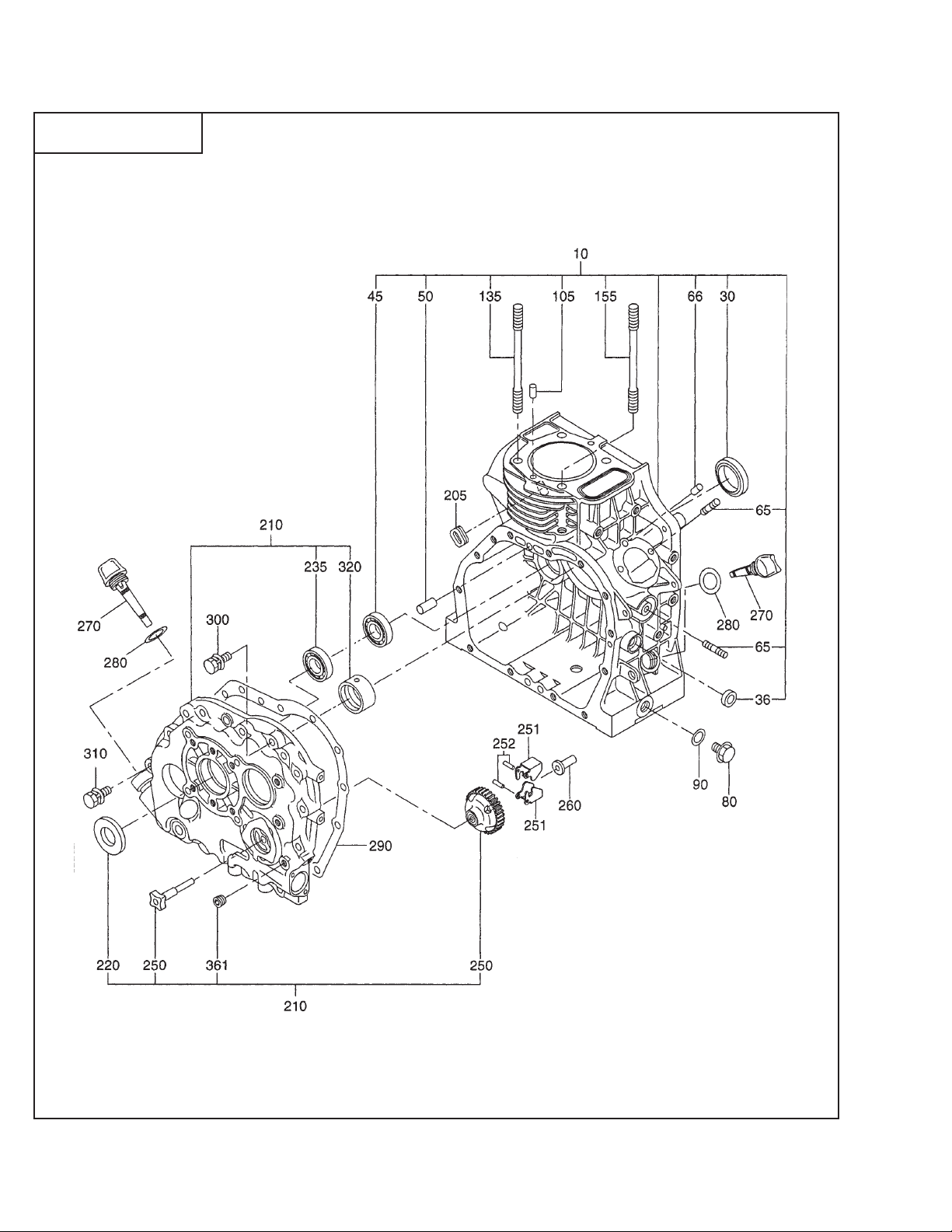
SECTION 1 CRANKCASE GROUP
FIG. 100
DY23-2 / DY27-2 - 6 - '00-07
Page 7

SECTION 1 CRANKCASE GROUP
REF. PART NO. DESCRIPTION QTY. REMARKS FROM-TO FIG.
10 243-10101-61 CRANKCASE CP 1 DY23-2 100
243-10105-61 CRANKCASE CP 1 DY23-2, Electric Start 100
10 244-10101-61 CRANKCASE CP 1 DY27-2 100
244-10105-61 CRANKCASE CP 1 DY27-2, Electric Start 100
30 044-03000-60 OIL SEAL 1 100
36 044-00800-30 OIL SEAL 1 100
45 060-01700-40 BALL BEARING 1 100
50 005-26081-80 DOWEL PIN 2 100
65 001-37062-21 STUD 3 100
66 031-00500-10 DOWEL PIN 1 100
80 040-11400-30 PLUG 2 100
90 021-11400-20 GASKET 2 100
105 031-00600-10 DOWEL PIN 2 100
135 244-16002-1 1 TENSION BOL T CP 3 100
155 244-16002-1 1 TENSION BOL T CP 1 100
205 243-75001-03 GROMMET 1 Electric Start 100
210 244-11009-21 MAIN BEARING COVER CP 1 1 00
220 044-03000-30 OIL SEAL 1 100
250 243-45011-07 GOVERNOR GEAR SET 1 100
251 220-41601-03 FLYWEIGHT 2 100
252 030-73000-70 PIN 2 100
260 205-41901-03 GOVERNOR SLEEVE 1 100
270 214-63601-13 OIL GAUGE 2 100
280 021-32000-10 GASKET 2 100
290 243-15026-03 GASKET, main bearing cover 1 100
300 001-13083-50 BOLT and WASHER AY 12 100
310 001-13084-00 BOLT and WASHER AY 1 100
320 243-15801-03 MAIN BEARING 1 STD. 100
243-15802-03 MAIN BEARING 1 0.25mm undersize 100
243-15803-03 MAIN BEARING 1 0.50mm undersize 100
361 212-15008-13 BLIND PLUG 1 100
DY23-2 / DY27-2 - 7 - '00-07
Page 8
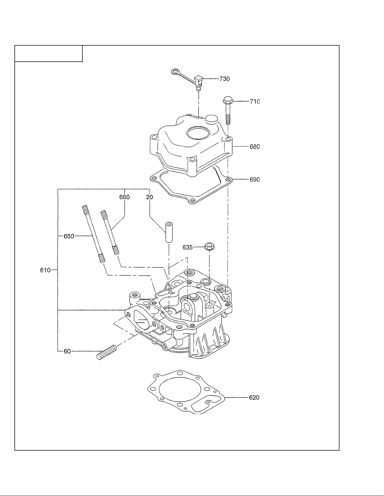
SECTION 1 CRANKCASE GROUP
FIG. 110
DY23-2 / DY27-2 - 8 - '00-07
Page 9
SECTION 1 CRANKCASE GROUP
REF. PART NO. DESCRIPTION QTY. REMARKS FROM-TO FIG.
20 243-14204-13 VALVE GUIDE 2 110
60 001-37082-01 STUD 2 110
610 243-13001-71 CYLINDER HEAD CP 1 110
620 243-15027-13 GASKET, T= 0.2 1 Select one piece only, DY23-2 110
243-15028-13 GASKET, T= 0.3 1 Select one piece only, DY23-2 110
620 244-15027-13 GASKET, T= 0.2 1 Select one piece only, DY27-2 110
244-15028-13 GASKET, T= 0.3 1 Select one piece only, DY27-2 110
635 018-00900-10 FLANGE NUT 4 110
650 001-39066-00 STUD 1 110
660 010-50601-50 STUD 1 110
680 243-17101-01 ROCKER COVER CP 1 110
690 243-1 5032-13 GASKET, rocker cover 1 110
710 011-00601-70 FLANGE BOLT 4 110
730 243-15030-03 PLUG 1 110
*960 255-99001-07 GASKET SET 1 DY23-2
*960 256-99001-07 GASKET SET 1 DY27-2
* The gasket set for the DY23-2 contains the following:
Fig. 100 items 90, 280, 290
Fig. 110 items 620, 690
Fig. 310 items 340, 555
* The gasket set for the DY27-2 contains the following:
Fig. 100 items 90, 280, 900
Fig. 110 items 620, 690
Fig. 310 items 340, 510-2, 555
DY23-2 / DY27-2 - 9 - '00-07
Page 10

SECTION 2 CRANKSHAFT GROUP
FIG. 200
430
440
DY23-2 / DY27-2 - 10 - '00-07
Page 11

SECTION 2 CRANKSHAFT GROUP
REF. PART NO. DESCRIPTION QTY. REMARKS FROM-TO FIG.
10 244-20401-1 1 CRANKSHAFT CP 1 200
25 060-03500-20 BALL BEARING 1 200
50 002-18180-00 NUT 1 200
60 003-20180-00 SPRING WASHER 1 200
70 032-30300-10 WOODRUFF KEY 1 2 00
85 243-25001-03 THRUST WASHER, T=0.8 1 Select one piece only 200
243-25002-03 THRUST WASHER, T=1.0 1 Select one piece only 200
243-25003-03 THRUST WASHER, T=1.2 1 Select one piece only 200
86 01 1-00600-10 FLANGE BOLT 2 200
210 243-24301-01 BALANCER CP 1 200
215 023-01700-20 SPACER, T= 0.8 1 Select one piece only 200
023-01700-30 SPACER, T= 1.0 1 Select one piece only 200
023-01700-40 SPACER, T= 1.2 1 Select one piece only 200
310 243-22510-00 CONNECTING ROD AY 1 200
320 243-23002-03 CONNECTING ROD BOLT 2 200
350 243-23301-03 PISTON PIN 1 200
360 243-23401-13 PISTON 1 STD., DY23-2 200
243-23402-13 PISTON 1 0.25mm oversize, DY23-2 200
243-23403-13 PISTON 1 0.50mm oversize, DY23-2 200
360 244-23401-13 PISTON 1 STD., DY27-2 200
244-23402-13 PISTON 1 0.25mm oversize, DY27-2 200
244-23403-13 PISTON 1 0.50mm oversize, DY27-2 200
370 243-23501-27 PISTON RING SET 1 STD., DY23-2 200
243-23502-27 PISTON RING SET 1 0.25mm oversize, DY23-2 2 00
243-23503-27 PISTON RING SET 1 0.50mm oversize, DY23-2 2 00
370 244-23501-27 PISTON RING SET 1 STD., DY27-2 200
244-23502-27 PISTON RING SET 1 0.25mm oversize, DY27-2 2 00
244-23503-27 PISTON RING SET 1 0.50mm oversize, DY27-2 2 00
380 056-52000-30 CLIP 2 200
395 243-22801-03 LARGE END BEARING 2 STD. 200
243-22802-03 LARGE END BEARING 2 0.25mm undersize 200
243-22803-03 LARGE END BEARING 2 0.50mm undersize 200
430 244-17501-13 ADAPTER 1 200
440 001-13082-50 BOLT and WASHER AY 4 200
500 243-22410-13 FLYWHEEL 1 200
DY23-2 / DY27-2 - 11 - '00-07
Page 12

SECTION 3 INTAKE and EXHAUST GROUP
FIG. 300
DY23-2 / DY27-2 - 12 - '00-07
Page 13

SECTION 3 INTAKE and EXHAUST GROUP
REF. PART NO. DESCRIPTION QTY. REMARKS FROM-TO FIG.
10 255-31703-01 CAMSHAFT CP 1 300
35 243-35503-23 RELEASE LEVER 1 3 00
36 005-19031-00 SPRING PIN 1 300
38 243-35505-03 RELEASE LEVER 1 3 00
39 243-35022-03 SHAFT , release 1 300
41 005-26081-80 DOWEL PIN 1 300
45 243-35021-03 SPRING, release 1 30 0
50 243-33301-03 TAPPET 2 300
60 243-33601-03 V AL VE SPRING 2 30 0
70 243-33701-13 SPRING RET AINER 2 300
75 243-33801-13 RETAINER LOCK 4 30 0
80 243-33401-23 INTAKE VALVE 1 300
85 237-16008-01 STEM SEAL 1 3 00
90 243-33501-23 EXHAUST VA LVE 1 300
100 023-01900-20 SPACER, T= 0.8 1 Select one piece only 300
023-01900-30 SPACER, T= 1.0 1 Select one piece only 300
200 243-35034-03 ROCKER SHAFT 1 300
210 243-35032-01 PUSH ROD CP 2 300
220 243-36002-01 ROCKER ARM CP 2 300
230 014-90800-21 ADJUSTING SCREW 2 300
240 017-00800-90 NUT 2 300
DY23-2 / DY27-2 - 13 - '00-07
Page 14

SECTION 3 INTAKE and EXHAUST GROUP
FIG. 310
DY23-2 / DY27-2 - 14 - '00-07
Page 15

SECTION 3 INTAKE and EXHAUST GROUP
REF. PART NO. DESCRIPTION QTY. REMARKS FROM-TO FIG.
300 255-30103-00 MUFFLER AY 1 310
310 243-30101-51 MUFFLER CP 1 310
320 243-34201-01 MUFFLER COVER CP 1 310
340 243-35002-03 GASKET, exhaust 1 310
350 002-19080-00 NUT 2 310
360 001-10061-00 BOLT and WASHER AY 4 310
380 243-37002-11 TAIL PIPE CP 1 310
395 015-00400-60 TAPPING SCREW 3 310
500 243-33101-13 INTAKE MANIFOLD 1 310
510 243-32601-00 AIR CLEANER AY 1 310
-2 243-32651-08 PACKING 1 310
-7 243-32650-08 PACKING 1 310
-110 243-32640-08 COVER CP 1 310
-120 243-32620-08 BACK PLATE CP 1 310
-160 243-32660-08 WASHE R 1 310
-170 243-32670-08 WING BOLT 1 310
520 243-32600-08 ELEMENT CP 1 310
525 243-32611-08 ELEMENT 1 310
555 243-35503-13 GASKET , intake manifold 1 310
556 001-13083-50 BOLT and WASHER AY 2 310
580 001-13061-20 BOLT and WASHER AY 2 310
584 001-13081-60 BOLT and WASHER AY 1 310
900 243-92302-03 LABEL, air cleaner 1 310
DY23-2 / DY27-2 - 15 - '00-07
Page 16

SECTION 4 GOVERNOR GROUP
FIG. 400
DY23-2 / DY27-2 - 16 - '00-07
Page 17

SECTION 4 GOVERNOR GROUP
REF. PART NO. DESCRIPTION QTY. REMARKS FROM-TO FIG.
10 243-42902-21 CONTROL LINK CP 1 400
20 243-42301-12 GOVERNOR LEVER 1 400
21 002-18080-00 NUT 1 400
22 003-20080-00 SPRING WASHER 1 400
80 243-42503-01 GOVERNOR SPRING CP 1 400
310 243-43301-30 SPEED CONTROL AY 1 400
340 227-43501-13 STOP PLATE 1 400
350 227-45002-03 SPRING WASHER 1 400
360 004-31041-00 SCREW 2 400
380 017-60600-30 SELF LOCK NUT 1 400
390 243-44202-01 WIRE BRACKET 1 CP 1 400
410 243-44210-01 WIRE BRACKET 2 CP 1 400
415 243-46001-03 RETURN SPRING 1 400
490 002-18060-00 NUT 2 400
491 001-66063-00 BOLT 1 400
495 243-45002-03 BOLT 1 400
496 003-10060-00 WASHER 1 400
497 010-00603-70 BOLT 1 400
500 255-40166-01 CONTROL PANEL CP 1 400
501 001-14061-20 BOLT and WASHER AY 2 400
502 001-13081-60 BOLT and WASHER AY 3 400
510 243-92101-03 LABEL, operation 1 400
520 243-92102-03 LABEL, operation 1 400
650 243-45502-00 SMOKE SET AY 1 400
660 002-27100-00 NUT 1 400
DY23-2 / DY27-2 - 17 - '00-07
Page 18

SECTION 5 COOLING and STARTING GROUP
FIG. 500
DY23-2 / DY27-2 - 18 - '00-07
Page 19

SECTION 5 COOLING and STARTING GROUP
REF. PART NO. DESCRIPTION QTY. REMARKS FROM-TO FIG.
10 243-51201-21 BLOWER HOUSING CP 1 500
40 001-13082-00 BOLT and WASHER AY 2 500
60 243-52601-33 CYLINDER BAFFLE 1 500
80 011-00600-10 FLANGE BOLT 5 500
150 001-13083-00 BOLT and WASHER AY 2 500
210 243-50201-20 RECOIL STARTER AY 1 50 0
-1 106-50116-08 SPIRAL SPRING 1 500
-2 239-50220-08 REEL CP 1 5 0 0
-3 243-50110-08 STARTER ROPE 1 500
-4 236-50101-08 STARTER KNOB 1 500
-5 106-50128-18 RATCHET 2 500
-6 106-50132-08 FRICTION SPRING 1 500
-7 106-50136-18 RETURN SPRING 1 500
-8 106-50144-08 FRICTION PLATE 1 500
-9 106-50185-08 THRUST WASHER 1 500
-10 106-50186-08 CLIP 1 500
-11 243-50145-08 STARTING PULLEY 1 500
215 243-95004-13 LABEL, diesel mark 1 500
230 001-14061-20 BOLT and WASHER AY 3 500
DY23-2 / DY27-2 - 19 - '00-07
Page 20

SECTION 6 FUEL, LUBRICANT GROUP
FIG. 600
DY23-2 / DY27-2 - 20 - '00-07
Page 21

SECTION 6 FUEL, LUBRICANT GROUP
REF. PART NO. DESCRIPTION QTY. REMARKS FROM-TO FIG.
10 243-60102-41 FUEL TANK CP 1 600
16 255-91701-03 LABEL, trademark 1 DY23-2 60 0
256-91701-03 LABEL, trademark 1 DY27-2 60 0
20 243-91907-13 LABEL, instruction 1 600
27 073-20039-00 LABEL, warning 1 600
30 043-04300-15 FUEL TANK CAP CP 1 600
40 064-13600-10 FUEL FILTER 1 6 00
80 085-14500-00 RUBBER PIPE 1 4.5 X 9 X 45 600
81 085-14500-00 RUBBER PIPE 1 4.5 X 9 X 95 600
86 228-65032-13 CHECK VALVE 1 600
88 150-75201-03 CLAMP 1 600
89 001-10061-00 BOLT and WASHER AY 1 600
90 056-10800-10 HOSE CLAMP 5 600
95 056-10800-20 HOSE CLAMP 1 600
100 085-00500-40 VINYL PIPE 1 5 X 8 X 120 600
105 001-13082-00 BOLT and WASHER AY 2 600
DY23-2 / DY27-2 - 21 - '00-07
Page 22

SECTION 6 FUEL, LUBRICANT GROUP
FIG. 610
DY23-2 / DY27-2 - 22 - '00-07
Page 23

SECTION 6 FUEL, LUBRICANT GROUP
REF. PART NO. DESCRIPTION QTY. REMARKS FROM-TO FIG.
250 243-63201-00 NOZZLE AY 1 610
-1 243-63204-08 NOZZLE 1 610
260 228-65004-03 GASKET, nozzle 1 610
265 002-38060-00 FLANGE NUT 4 610
270 243-66001-01 BRACKET CP , nozzle 1 1 610
300 255-63103-00 INJECTION PUMP AY 1 6 10
-1 243-63131-08 PLUNGER AY 1 610
-2 243-63103-08 DELIVERY VALVE 1 610
-3 243-63104-08 DELIVERY SPRING 1 6 10
-4 243-63105-08 GASKET 1 610
-5 243-63107-08 O RING 1 610
-6 243-63129-08 O RING 2 610
-21 243-63130-08 SCREW 2 610
305 243-65001-03 GASKET, T= 0.1 1 Select one piece only 610
243-65002-03 GASKET, T= 0.2 1 Select one piece only 610
243-65003-03 GASKET, T= 0.3 1 Select one piece only 610
310 085-10600-00 RUBBER PIPE 1 6 X 12 X 120 610
330 085-10600-00 RUBBER PIPE 1 6 X 12 X 180 610
340 085-14500-00 RUBBER PIPE 1 4.5 X 9 X 90 610
350 085-14500-00 RUBBER PIPE 1 4.5 X 9 X 315 610
355 056-11 100-20 HOSE CLAMP 4 610
356 056-10800-10 HOSE CLAMP 4 610
400 243-62101-20 FUEL FILTER A Y 1 6 10
-7 228-62112-08 PACKING 1 610
-8 228-62111-08 PLUG 1 610
420 243-66520-10 T-CONNECTOR AY 1 610
-1 243-66521-08 NUT 1 610
-2 243-66506-08 PACKING 1 610
430 243-63301-21 INJECTION PIPE CP 1 610
600 243-64301-00 OIL FILTER A Y 1 6 10
610 001-14061-60 BOLT and WASHER AY 2 610
620 006-26202-00 O RING 1 610
700 228-63902-03 OIL PUMP , outer 1 610
710 006-26103-30 O RING 1 610
720 243-66020-01 COVER CP , oil pump 1 610
730 004-11061-60 SCREW, countersink 3 610
DY23-2 / DY27-2 - 23 - '00-07
Page 24

SECTION 7 ELECTRIC DEVICE GROUP
FIG. 700
DY23-2 / DY27-2 - 24 - '00-07
Page 25

SECTION 7 ELECTRIC DEVICE GROUP
REF. PART NO. DESCRIPTION QTY. REMARKS FROM-TO FIG.
10 243-70110-41 FLYWHEEL CP 1 700
11 243-70102-21 CHARGE COIL CP 1 700
20 243-71002-13 RING GEAR 1 700
35 004-35062-50 SCREW and WASHER AY 2 700
90 226-75101-03 CLAMP 1 700
92 004-35061-00 SCREW and WASHER AY 1 700
130 001-14083-00 BOL T and W ASHER AY 2 700
170 001-13081-60 BOL T and W ASHER AY 1 700
200 243-40601-11 CONTROL BOX CP 1 700
210 073-20010-90 LABEL, starter switch 1 700
220 066-00003-30 SWITCH 1 700
-1 066-00099-80 KEY 2 700
230 243-71401-01 DIODE RECTIFER CP 1 700
240 001-10061-00 BOL T and W ASHER AY 1 700
261 056-60001-70 CLAMP 2 700
262 001-13081-20 BOL T and W ASHER AY 1 700
340 243-73104-11 WIRE 2 CP 1 700
DY23-2 / DY27-2 - 25 - '00-07
Page 26

SECTION 7 ELECTRIC DEVICE GROUP - STARTER MOTOR
FIG. 710
DY23-2 / DY27-2 - 26 - '00-07
Page 27

SECTION 7 ELECTRIC DEVICE GROUP - STARTER MOTOR
REF. PART NO. DESCRIPTION QTY. REMARKS FROM-TO FIG.
120 255-70502-00 STARTING MOTOR AY 1 710
-1 255-70580-08 YOKE AY 1 710
-2 255-70551-08 BRUSH SET 1 710
-3 228-70516-08 BRUSH SPRING 4 710
-4 255-70531-08 BRUSH HOLDER AY 1 710
-6 255-70561-08 AMATEUR A Y 1 710
-7 255-70521-08 PINION AY 1 710
-8 210-70534-08 PINION STOPPER SET 1 710
-9 255-70501-08 GEAR CASE AY 1 710
-10 228-70514-08 BRUSH (-) 2 710
-11 255-70505-08 REAR COVER AY 1 710
-12 210-70542-08 REAR COVER METAL 1 710
-14 243-70525-08 SHIFT LEVER KIT 1 710
-15 255-70515-08 MAGNETIC SWITCH AY 1 710
-17 207-70524-08 THROUGH BOLT 2 710
-25 210-70533-08 THRUST WASHER KIT 1 710
-29 210-70542-08 REAR COVER METAL 1 710
-30 255-70570-08 DUST COVER KIT 1 710
-32 228-70522-08 BOLT 2 710
140 002-28080-00 NUT 1 710
160 003-20080-00 SPRING WASHER 1 710
DY23-2 / DY27-2 - 27 - '00-07
Page 28

SECTION 8 ACCESSORIES GROUP
FIG. 800
40
DY23-2 / DY27-2 - 28 - '00-07
Page 29

SECTION 8 ACCESSORIES GROUP
REF. PART NO. DESCRIPTION QTY. REMARKS FROM-TO FIG.
10 243-90301-00 TOOL KIT 1 800
30 243-65006-00 OIL FEEDER AY 1 800
40 207-26001-03 KEY 1 800
DY23-2 / DY27-2 - 29 - '00-07
Page 30

PRINTED IN THE USA
 Loading...