

Page 1

PILOT’S OPERATING HANDBOOK
SUPPLEMENT
DR400/135CDI
Document n° 1001639GB
Page 2

Page 3

Supplement POH DR400/120D, DR400/140B,
DR400/180R, DR400/200R, DR400/RP
Pilot´s Operating Handbook
Supplement
for the
DR400/120D
DR400/140B
DR400/180R
DR400/200R
DR400/RP
Equipped with TAE 125 Installation
TYPE ................................ DR 400
MODEL No. ......................
SERIAL No. ......................
REGISTER No. ................
This supplement must be attached to the EASA approved Pilot´s
Operating Handbook of the DR400/120D, DR400/140B, DR400/180R,
DR400/200R or DR400/RP when the TAE 125-01 or TAE 125-02-99
installation has been installed in accordance with EASA.A.S.01380 or
EASA STC 10014219.
The information contained in this supplement supersedes or adds to the
information published in the EASA approved Pilot´s Operating Handbook
only as set forth herein.
For limitations, procedures, performance and loading information not
contained in this supplement, consult the EASA approved Pilot´s
Operating Handbook.
This supplement Pilot‘s Operating Handbook is approved with EASA
STC 10014219.
Doc.Nr.: 1001639GB
Issue 3 – July 2014 Page i
Page 4

Supplement POH DR400/120D, DR400/140B,
DR400/180R, DR400/200R, DR400/RP
Page - ii Issue 3 - July 2014
Page 5

Supplement POH DR400/120D, DR400/140B,
DR400/180R, DR400/200R, DR400/RP
Issue/
Rev.
Section
Description
Approval
D
at
Endorsed
2/1
2
New fuel,
new gearbox oil
M
ar
c
h
1
6
2
0
Revision No. 1 to AFM
supplement ref 60-0310-
60022 is approved under
the authority of DOA ref.
EASA.21J.010.
Date: March 16 ,2012
Office of Airworthiness
4
Procedures updated
3/0
all
Change of TC holder
Initial issue C.E.A.P.R
Numbering of CEAPR
documents
J
ul
y
2
0
EASA STC 10014219
transfer
APPROVAL
Issue 2:
The content of approved sections is approved by EASA. All other content
is approved by TAE under the authority of EASA DOA No.
EASA.21J.010 in accordance with Part 21.
Issue 3:
The content of approved sections is approved by EASA, transfer of STC
10014219. C.E.A.P.R is TC holder.
LOG OF REVISIONS
The parts of the text which changed are marked with a vertical line on
the margin of the page.
Issue 3 – July 2014 Page iii
Page 6
Supplement POH DR400/120D, DR400/140B,
DR400/180R, DR400/200R, DR400/RP
Section
Issue/ Revision
Date
0
3/0
July 2014
1
3/0
July 2014
2
3/0
July 2014
3
3/0
July 2014
4
3/0
July 2014
5
3/0
July 2014
6
3/0
July 2014
7
3/0
July 2014
LIST OF EFFECTIVE SECTIONS
Page - iv Issue 3 - July 2014
Page 7

Supplement POH DR400/120D, DR400/140B,
DR400/180R, DR400/200R, DR400/RP
TABLE OF CONTENTS
APPROVAL .............................................................................................. iii
LOG OF REVISIONS ............................................................................... iii
LIST OF EFFECTIVE SECTIONS ........................................................... iii
ABBREVIATIONS .................................................................................... xi
SECTION 0
GENERAL
CONVENTIONS IN THIS HANDBOOK ................................................. 0-1
FOR DR400 AIRCRAFT FROM SERIAL NUMBER 2500 AND UP ...... 0-1
UPDATE AND REVISION OF THE MANUAL ....................................... 0-1
SECTION 1
DESCRIPTION
OVERALL DIMENSIONS ...................................................................... 1-1
ENGINE ................................................................................................. 1-1
PROPELLER.......................................................................................... 1-2
NOISE LIMITATION ............................................................................... 1-2
ELECTRICAL SYSTEM ......................................................................... 1-3
FADEC-RESET ...................................................................................... 1-6
FUELS, OILS and LIQUIDS ................................................................... 1-6
ENGINE OIL........................................................................................... 1-7
FUEL SYSTEM ...................................................................................... 1-7
OPTIONAL EXTENDED RANGE TANK ............................................... 1-8
INSTRUMENT PANEL.........................................................................1-11
HEATING AND VENTILATION ............................................................1-20
Issue 3 – July 2014 Page v
Page 8

Supplement POH DR400/120D, DR400/140B,
DR400/180R, DR400/200R, DR400/RP
SECTION 2
LIMITATIONS
APPROVED OPERATION .................................................................... 2-1
MAXIMUM ALTITUDE........................................................................... 2-1
FLIGHT LOAD FACTOR LIMITS AT MAXIMUM WEIGHT .................. 2-2
MAXIMUM AUTHORIZED WEIGHTS .................................................. 2-2
WEIGHT AND BALANCE ..................................................................... 2-2
LOAD PLANNING ................................................................................. 2-3
ENGINE OPERATING LIMITS .............................................................. 2-3
ENGINE INSTRUMENT MARKINGS ................................................... 2-6
GROUNDING (EARTHING) BEFORE AND DURING FUELING ......... 2-6
PERMISSIBLE FUEL GRADES ............................................................ 2-7
MAXIMUM FUEL QUANTITIES ............................................................ 2-7
PERMISSIBLE OIL GRADES ............................................................... 2-7
PERMISSIBLE COOLING LIQUID ....................................................... 2-8
LOAD LIMITS ........................................................................................ 2-8
OPERATIONAL LIMITATIONS IN THE “U” CATEGORY .................... 2-8
PLACARDS ........................................................................................... 2-9
Page - vi Issue 3 - July 2014
Page 9

Supplement POH DR400/120D, DR400/140B,
DR400/180R, DR400/200R, DR400/RP
SECTION 3
EMERGENCY PROCEDURES
ENGINE FAILURE OR LOSS OF POWER ........................................... 3-2
During takeoff roll ................................................................................... 3-2
Immediately after takeoff ....................................................................... 3-2
During flight ............................................................................................ 3-3
LANDING WITHOUT ENGINE POWER ............................................... 3-4
Restart after engine failure .................................................................... 3-5
FADEC malfunction in flight ................................................................... 3-6
ENGINE SHUT-DOWN IN FLIGHT ....................................................... 3-8
FIRE ....................................................................................................... 3-9
Engine fire on the ground, during starting ............................................. 3-9
Engine fire in flight ................................................................................ 3-9
Electrical fire ........................................................................................3-10
ROUGH ENGINE OPERATION ..........................................................3-11
Oil pressure too low .............................................................................3-11
Oil temperature too high ......................................................................3-12
Coolant temperature too high ..............................................................3-12
“Cool level” light illuminates .................................................................3-13
Gearbox temperature too high .............................................................3-13
Fuel temperature too low .....................................................................3-13
Propeller RPM too high ........................................................................3-14
Fluctuations in propeller RPM ..............................................................3-14
ICING ...................................................................................................3-14
ELECTRICAL POWER SUPPLY MALFUNCTION .............................3-16
If the “ALT” light is lit or the ammeter shows battery discharge during
normal engine operation for more than 5 minutes ...............................3-17
INADVERTENT SPIN ..........................................................................3-18
LOSS OF ELEVATOR CONTROL ......................................................3-18
Issue 3 – July 2014 Page vii
Page 10

Supplement POH DR400/120D, DR400/140B,
DR400/180R, DR400/200R, DR400/RP
SECTION 4
NORMAL PROCEDURES
NORMAL OPERATING SPEEDS ......................................................... 4-1
Best rate of climb speed ........................................................................ 4-1
Maximum operating speed in turbulent air ............................................ 4-1
Never Exceed speed ............................................................................. 4-1
Maximum speed .................................................................................... 4-1
Landing speed, final approach .............................................................. 4-1
PRE-FLIGHT INSPECTION .................................................................. 4-2
CABIN INTERIOR CHECK BEFORE START-UP ................................ 4-5
STARTING THE ENGINE ..................................................................... 4-6
AFTER ENGINE START ....................................................................... 4-7
FADEC BACKUP BATTERY TEST ...................................................... 4-7
WARM UP ............................................................................................. 4-8
TAXIING ................................................................................................ 4-8
BEFORE TAKEOFF .............................................................................. 4-8
TAKEOFF ............................................................................................ 4-11
Short takeoff ....................................................................................... 4-11
Crosswind takeoff ................................................................................ 4-11
CLIMB .................................................................................................. 4-12
Normal climb (flaps up) ....................................................................... 4-12
CRUISE ............................................................................................... 4-12
DESCENT ........................................................................................... 4-13
Approach or downwind ........................................................................ 4-13
Final ..................................................................................................... 4-13
LANDING ............................................................................................. 4-14
Short landing ....................................................................................... 4-14
Overshoot procedure........................................................................... 4-14
AFTER LANDING ................................................................................ 4-14
ENGINE SHUT-DOWN ....................................................................... 4-14
After the engine stops ......................................................................... 4-14
PARKING BRAKE USE ...................................................................... 4-15
Brake on .............................................................................................. 4-15
Brake off .............................................................................................. 4-15
Page - viii Issue 3 – July 2014
Page 11

Supplement POH DR400/120D, DR400/140B,
DR400/180R, DR400/200R, DR400/RP
SECTION 5
PERFORMANCE
AIRSPEED INSTALLATION CALIBARTION ......................................... 5-1
STALL SPEEDS .................................................................................... 5-1
TAKEOFF PERFORMANCE ................................................................. 5-2
Takeoff distance, 1100 kg ...................................................................... 5-3
Takeoff distance, 1000 kg ...................................................................... 5-4
CLIMB PERFORMANCE ....................................................................... 5-5
Climb speeds ......................................................................................... 5-5
Rate of climb, Flaps retracted, 1100 kg ................................................. 5-6
Rate of climb, Flaps retracted, 1000 kg ................................................. 5-7
Time, fuel and distance to climb, Flaps retracted, 1100kg .................... 5-8
Time, fuel and distance to climb, Flaps retracted, 1000kg .................... 5-9
Maximum angle of climb in takeoff position .........................................5-10
Glide performance ...............................................................................5-10
CRUISE PERFORMANCE ..................................................................5-11
At maximum take-off weight, 1100 kg .................................................5-12
At take-off weight 980 kg .....................................................................5-15
LANDING PERFORMANCE ................................................................5-18
SECTION 6
WEIGHT AND BALANCE
USE OF WEIGHT AND BALANCE DIAGRAM ..................................... 6-3
Example of loading problem (dashed line on the diagram) ................... 6-3
SECTION 7
SUPPLEMENTS
No supplements
Issue 3 – July 2014 Page ix
Page 12

Supplement POH DR400/120D, DR400/140B,
DR400/180R, DR400/200R, DR400/RP
Page -x Issue 3 - July 2014
Page 13

Supplement POH DR400/120D, DR400/140B,
DR400/180R, DR400/200R, DR400/RP
ABBREVIATIONS
TAE Thielert Aircraft Engines GmbH, developing and
manufacturing company of the Centurion 2.0 S engine, (since
July 2013, Technify Motors GmbH).
FADEC Full Authority Digital Engine Control
CED 125 Compact Engine Display. Multifunctional instrument for
indication of engine data of the TAE 125-01 and TAE 125-02-
99 engine.
Issue 3 – July 2014 Page xi
Page 14

Supplement POH DR400/120D, DR400/140B,
DR400/180R, DR400/200R, DR400/RP
Page -xii Issue 3 – July 2014
Page 15

Supplement POH DR400/120D, DR400/140B,
DR400/180R, DR400/200R, DR400/RP
SECTION 0
GENERAL
CONVENTION IN THIS HANDBOOK
This manual contains the following convention and warnings. They
should be strictly followed to rule out personal injury, property damage,
and impairment to the aircraft´s operating safety or damage to it as a
result of improper functioning.
▲ WARNING: Non-compliance with these safety rules could lead to
injury or even death.
CAUTION: Non-compliance with these special notes
and safety measures could cause damage to the engine
or to the other components.
Note: Information added for a better understanding of an
instruction.
FOR DR400 AIRCRAFT FROM SERIAL NUMBER 2500 AND UP
This supplement is valid if the TAE 125-01 or TAE 125-02-99 aircraft
engine is installed.
UPDATE AND REVISION OF THE MANUAL
▲ WARNING: A safe operation is only assured with an up to date POH
supplement.
Note: The document number of this POH supplement is
published on the cover sheet of this supplement.
Issue 3 – July 2014 Page 0 - 1
Page 16

Supplement POH DR400/120D, DR400/140B,
DR400/180R, DR400/200R, DR400/RP
Page 0 - 2 Issue 3 – July 2014
Page 17

Supplement POH DR400/120D, DR400/140B,
DR400/180R, DR400/200R, DR400/RP
SECTION 1
DESCRIPTION
OVERALL DIMENSIONS
Wing span ................................................................ (28 ft 7.3 in) 8.72 m
Overall length ...............................................................(23 ft 8 in) 7.20 m
Overall height ........................................................... (7 ft 3.79 in) 2.23 m
Propeller ground clearance ............................................... (9.5 in) 0.26 m
ENGINE
Engine manufacturer ........................................... Technify Motors GmbH
Engine models ........................................ TAE 125-01 or TAE 125-02-99
The TAE 125-02-99 is the successor of the TAE 125-01. Both engine
variants have the same power output and the same propeller speeds but
different displacement. While the TAE 125-01 has 1689 ccm, the TAE
125-02-99 has 1991 ccm.
Both engine variants are liquid cooled in-line four-stroke 4-cylinder
engines with DOHC (double overhead camshaft) and are direct Diesel
injection engines with common-rail technology and turbocharging. Both
engine variants are controlled by a FADEC system. The propeller is
driven by a built-in gearbox (i = 1.69) with mechanical vibration damping
and overload release. The engine variants have an electrical self-starter
and an alternator.
▲ WARNING: The engine requires an electrical power source for
operation. If the main battery and alternator fail
simultaneously, the engine will operate for a very limited
time on FADEC backup battery power (TAE 125-02-99
installation).
Therefore, it is important to pay attention to indications of
alternator failure.
Issue 3 – July 2014 Page 1 - 1
Page 18

Supplement POH DR400/120D, DR400/140B,
DR400/180R, DR400/200R, DR400/RP
Due to the specific characteristic of the TAE 125 engine, all of the
information from the original DR400 flight manual recognized by EASA
are no longer valid with the reference to:
carburetor and carburetor pre-heating,
ignition magnetos and spark plugs, and
mixture control and priming system.
PROPELLER
Manufacturer ....................................... MT Propeller Entwicklung GmbH
Model ........................................................................... MTV-6-A/187-129
Number of blades ................................................................................... 3
Diameter ......................................................................................... 1.87m
Type ................................................................................ Constant Speed
NOISE LIMITATION
In compliance with the regulation ICAO, annex 16, Volume I, Part II,
Chapter X, the maximum acceptable noise level for the DR400/120D,
DR400/140B, DR400/180R, DR400/200R, DR400/RP at a certified max.
take-off weight of 980 kg (2161 lb) is 78.4 dB(A).
For the TAE 125-01 installation:
The noise level determined under the conditions of the abovementioned
regulation, with the MT Propeller MTV-6-A/187-129 propeller together
with "Akrapovic type for TAE 125" muffler, is 70.9 dB(A).
The noise level determined under the conditions of the abovementioned
regulation, with the MT Propeller MTV-6-A/187-129 propeller together
with no installed muffler, is 74.4 dB(A).
For the TAE 125-02-99 installation:
The noise level determined under the conditions of the abovementioned
regulation, with the MT Propeller MTV-6-A/187-129 propeller together
with "Akrapovic type for TAE 125" muffler, is 70.2 dB(A).
The noise level determined under the conditions of the abovementioned
regulation, with the MT Propeller MTV-6-A/187-129 propeller together
with “Langer LA 44” muffler, is 69.1 dB(A).
ELECTRICAL SYSTEM
The electrical system of the TAE 125 installation differs from the previous
Page 1 - 2 Issue 3 – July 2014
Page 19

Supplement POH DR400/120D, DR400/140B,
DR400/180R, DR400/200R, DR400/RP
installation and is equipped with the following operating and display
elements:
1. Rocker Switch "Battery"
The battery must be switched ON in normal operation.
2. The circuit breaker below the Rocker Switch "Battery" disables the
alternator. The alternator can be left ON always.
3. Key Switch "Starter"
This switch controls the starter motor only.
4. Voltmeter
5. Warning lamp "Alternator".
Illuminates when the power output of the alternator is too low or the
circuit breaker “Alternator” (Switch resp.) is switched off. Normally, this
warning lamp always illuminates when the “Engine Master” (“IGN” resp.)
is switched on without revolution and extinguished immediately after
starting the engine.
6. Switch "Engine Master"
The Engine Master switch controls the two redundant FADEC
components, and the back-up alternator excitation battery, with three
independent contacts. It is protected against unintentional switching with
a pull-to-actuate mechanism and a guard. The alternator excitation
battery is used to ensure that the alternator continues to function in any
circumstances even if the main battery fails.
7. Switch "FORCE B"
If the FADEC does not automatically switch from A-FADEC to the BFADEC in case of an emergency despite of obvious necessity, this
switch allows to switch manually to the B-FADEC.
8. FADEC Backup Battery (TAE 125-02-99 installation)
The backup battery ensures power supply to A-FADEC only when supply
from main battery and alternator is interrupted. This allows continued
engine operation for limited time only.
Issue 3 – July 2014 Page 1 - 3
Page 20
Supplement POH DR400/120D, DR400/140B,
DR400/180R, DR400/200R, DR400/RP
STARTER
PITOT HEAT
(optional)
ALTERNATOR
BATTERY
EXTERNAL POWER
PLUG
SWITCH TYPE
CIRCUIT BREAKER
TRIP FREE
CIRCUIT BREAKER
SWITCH
PUSH
BUTTON
WARNING
LIGHT
FADEC
PULL TO
FORCE B
ENGINE MASTER
ALTERNATOR
BATTERY
TEST
START
(key)
GLOW
CED
COMPACT ENGINE DISPLAY
TEST / ACK
TURN INDICATOR
VOLTMETER
STROBE
LIGHT
NAVIGATION
LIGHT
TAXI
LIGHT
LANDING
LIGHT
ELECT.
PUMP
FUEL
TEMPERATURE
PITOT
HEAT
DIMMERS
AVIONICS
STALL WARNING
FUEL GAUGE
ANNUNCIATOR PANEL
FUEL
TEMPERATURE
ICE ZONE
ELECTRONICS INTERNATIONAL
C
RDO & inst.
Cabin
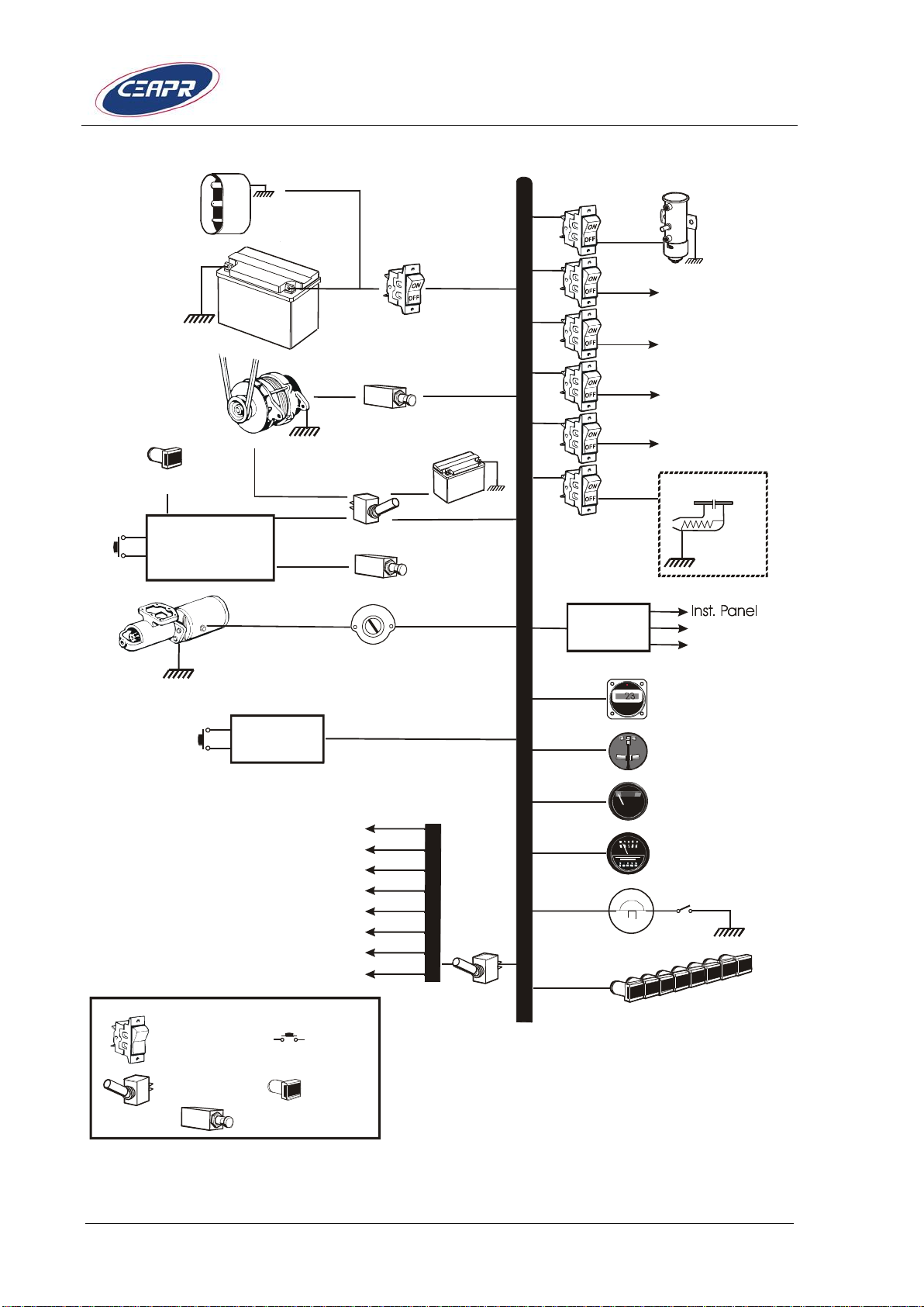
Figure 1-1 Simplified block diagram
Page 1 - 4 Issue 3 – July 2014
Page 21
Supplement POH DR400/120D, DR400/140B,
DR400/180R, DR400/200R, DR400/RP
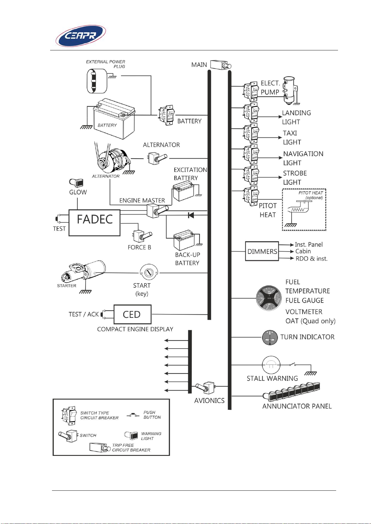
Figure 1-2 Simplified Block Diagram with FADEC backup battery installed
Issue 3 – July 2014 Page 1 - 5
Page 22

Supplement POH DR400/120D, DR400/140B,
DR400/180R, DR400/200R, DR400/RP
FADEC-RESET
In case of a FADEC-warning, one or both FADEC warning lamps are
flashing. If then the "FADEC" Test Knob is pressed for at least 2
seconds:
a) the active warning lamps will extinguish if it was a LOW category
warning.
b) the active warning lamps will be illuminated steady if it was a
HIGH category warning.
CAUTION: If a FADEC-warning occurred, contact your
service center. Next flight is not permitted.
When a high category warning occurs the pilot should land as soon as
practical, since the affected FADEC ECU has diagnosed a severe fault.
A low category fault has no significant impact on engine operation.
Refer also to the engine manual OM-02-01 or OM-02-02 for additional
information.
FUELS, OILS and LIQUIDS
Approved fuels, oil and liquids are published in Section 2 - Limitations of
this POH Supplement.
▲ WARNING: The engine must not be started if the oil or coolant level is
too low.
CAUTION: Use of unapproved fuels, oil and coolant may result in
damage to the engine and fuel system components,
resulting in possible engine failure.
CAUTION: Normally it is not necessary to fill the cooling liquid or
gearbox oil between maintenance intervals. If the level is
too low, please notify the service department
immediately.
Page 1 - 6 Issue 3 – July 2014
Page 23

Supplement POH DR400/120D, DR400/140B,
DR400/180R, DR400/200R, DR400/RP
ENGINE OIL
Oil quantity between dipstick min and max indication: .................. 1 liter
Total engine capacity including filters and coolers: .................. 6.7 liters
Approved grades: .................................. Refer to Section 2 – Limitations
CAUTION: Use the approved oil with exact declaration only!
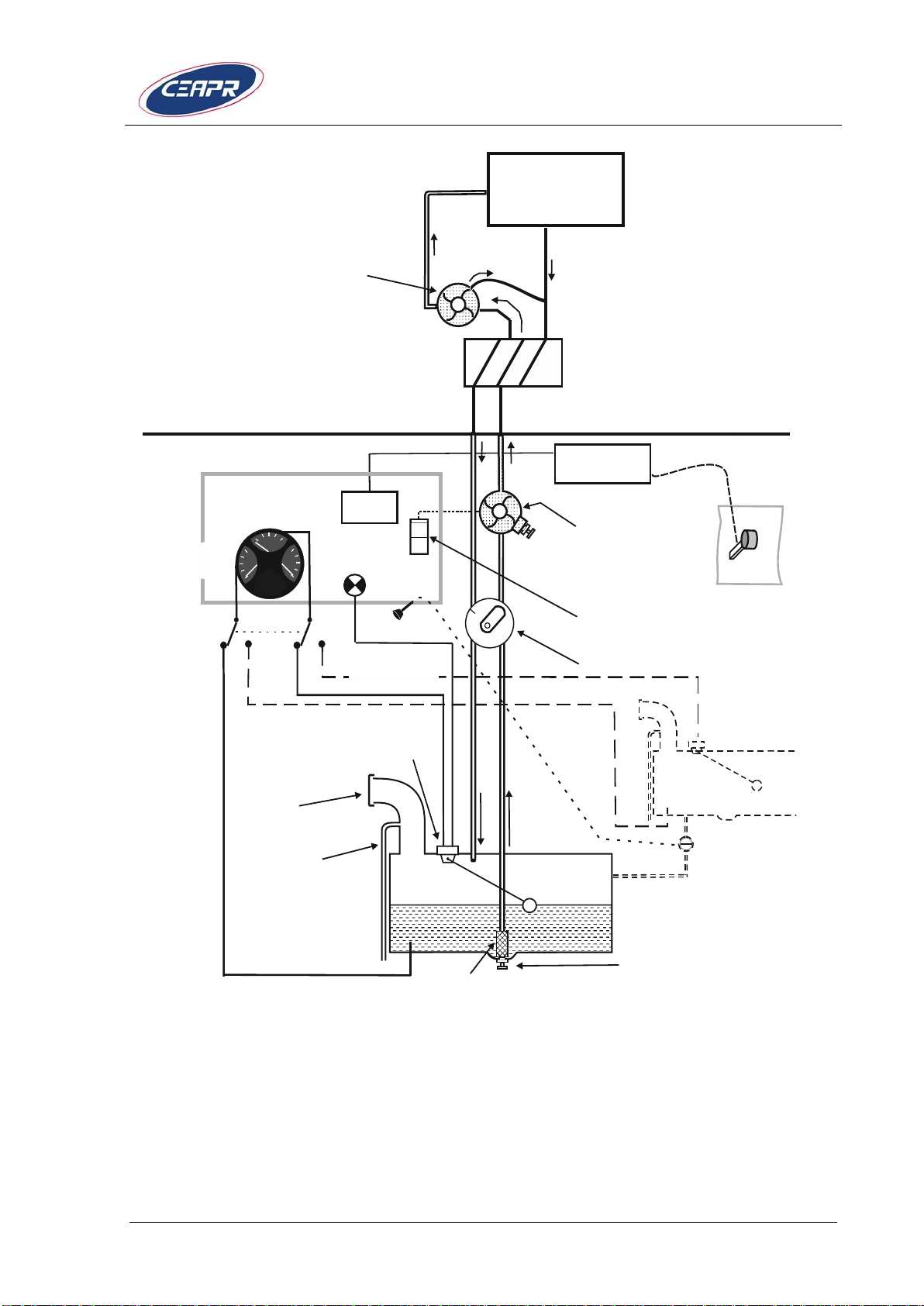
FUEL SYSTEM
The fuel system of the TAE 125 installation includes a variant of the
original standard tank of the DR400, plus a level sender and display, and
an independent low-level warning light. An additional sensor and display
for fuel temperature is installed.
The fuel flows out of the tank to the Fuel Selector Valve which has
positions ON and OFF.
The electrically driven fuel pump supports the fuel flow to the filter
module if required. Upstream to the fuel filter module a thermostatcontrolled fuel pre-heater is installed. Then, the engine-driven feed pump
and the high-pressure pump supply the rail, from where the fuel is
injected into the cylinders depending upon the position of the thrust lever
and regulation by the FADEC.
Surplus fuel flows to the filter module and then through the fuel selector
valve back into the tank. A temperature sensor in the filter module
controls the heat exchange between the fuel feed and return. Since
Diesel fuel tends to form paraffin at low temperatures, the information in
Section 2 “Limitations“ pertaining to fuel temperature have to be
observed. The fuel return ensures a quicker warm up of the fuel in the
tank.
Issue 3 – July 2014 Page 1 - 7
Page 24
Supplement POH DR400/120D, DR400/140B,
DR400/180R, DR400/200R, DR400/RP
Fuel capacity
Tank
Total usable
fuel
Total unusable fuel
Total capacity
109 liters
28.7 US gal
24 imp gal
1 liter
0.26 US gal
0.22 imp gal
110 liters
29 US gal
24.2 imp gal
If Diesel fuel is used, Diesel fuel according DIN EN 590 has to be used
exclusively.
Note: There are differences in the national
supplements to EN 590. Approved are Diesel fuels with
the addition DIN EN 590.
Table 1-1 Fuel Capacity
OPTIONAL EXTENDED RANGE TANK
▲ WARNING: The optional tank is only approved for Jet-A1
The total fuel capacity can be increased to 160 l / 35.2 Imp gal / 42.24
US gal (159 l / 35 Imp gal / 42 US gal usable) by installing an optional
fuel tank of 50 l / 11 Imp gal / 13.2 US gal.
The optional tank is located in the fuselage, aft of the rear seat. The fuel
from the optional tank can be transferred into the main tank by pulling the
transfer valve control, located on the instrument panel. The fuel
temperature and the fuel level of the optional tank are displayed either on
the triple indicator or on the quad indicator (depending on the instrument
panel model) when a momentary switch is pushed (warning LED signal).
Note: The main fuel tank must be empty enough
to receive full quantity from the optional fuel tank.
Since the optional fuel tank is not heated, it is limited to the use of
JET A-1 only to prevent a potential clogging of Diesel Fuel to low
temperature.
Page 1 - 8 Issue 3 – July 2014
Page 25
Supplement POH DR400/120D, DR400/140B,
DR400/180R, DR400/200R, DR400/RP
Fuel shut-off
with fuel filter
and
drain-valve
Electric
fuel pump,
Switch
Fire-wall
Fuel quantity
transmitter
Vent/overflow line
Filler
port
Drain valve
Strainer
Power lever
Fuel
quantity
ON
OFF
Option.fuel
quantity
CED
6
8
10 12 14
16
FUEL
F
½EFUEL
2
1
3WESTACH
Fuel
low-level
Fuel
temperature
Optional
switch
Optional tank
50 litres
Engine-driven
fuel pump
FU EL
FIL T E R
Excess from
fuel injectors
Excess from
fuel pump
ENGINE
VOLTSFUEL
F
½
½
EEFUEL
FUEL
2
1
3
4
WESTACH
F
FADEC
Figure 1-3/1 fuel system simplified diagram (Instrument panel models #1
and #2)
Issue 3 – July 2014 Page 1 - 9
Page 26
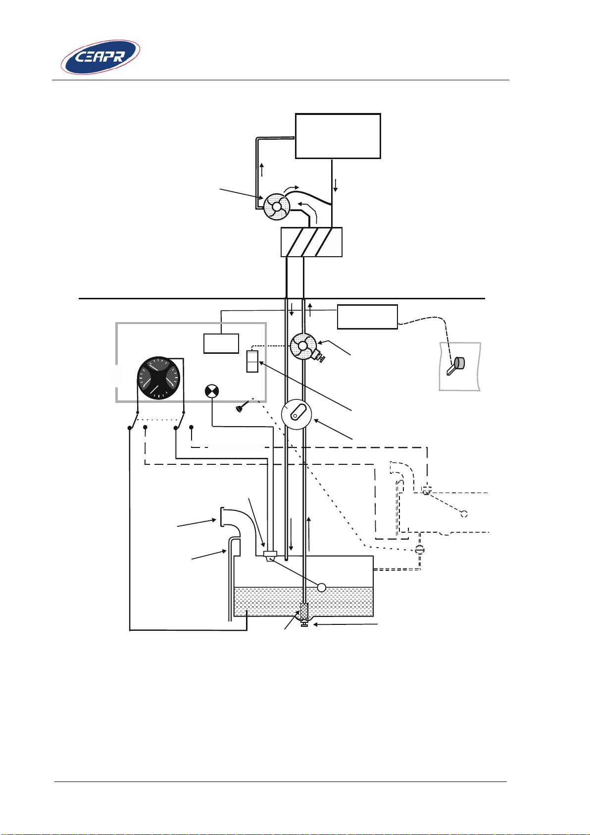
Supplement POH DR400/120D, DR400/140B,
DR400/180R, DR400/200R, DR400/RP
Fuel shut-off
with fuel filter
and
drain-valve
Electric
fuel pump,
Switch
Engine-driven
fuel pump
Fire-wall
Fuel quantity
transmitter
Vent/overflow line
Filler
port
Drain valve
Strainer
Power lever
Fuel
quantity
ON
OFF
Option.fuel
quantity
FU EL
FIL T ER
CED
Excess from
fuel injectors
Excess from
fuel pump
6
8
10 12
14
16
FUEL
F
½EFUEL
2
1 3WESTACH
Fuel
low-level
Fuel
temperature
Optional
switch
Optional tank
50 litres
VOLTS
FUEL
°C
½
E
OAT
FUEL
2
1 3
4
WESTACH
F
ENGINE
FADEC
Figure 1-2 Fuel system simplified diagram (Instrument panel model #3)
Page 1 - 10 Issue 3 – July 2014
Page 27
Supplement POH DR400/120D, DR400/140B,
DR400/180R, DR400/200R, DR400/RP
G
M
A
3
4
0
K
M
D
1
5
0
V
H
F
/
V
O
R
K
X
1
5
5
-
4
2
1
5
6
8
1
0
1
1
1
2
1
3
1
5
2
7
9
1
6
1
7
1
8
1
9
2
9
2
8
2
7
2
6
2
5
2
4
2
4
3
0
3
1
3
2
3
4
3
6
3
5
3
7
4
2
3
9
2
0
2
2
2
2
2
3
2
3
3
3
3
4
3
8
4
0
4
1
4
3
4
4
R
P
M
OPO
T
2
3
6
5
0
1
4
0
b
arC
L
O
A
D
%
t
r
/
m
i
n
2
3
0
0
6
0
1
0
5
1
2
0
C
C
CTG
T
1
0
0
O
F
F
L
R
B
O
T
H
S
T
2
0
707
070707060
4
0
4
0
2
0
2
1
1
4
5
1
4
5
Q
U
A
R
T
Z
-
C
H
R
O
N
O
M
E
T
E
R
L
C
-
2
R
S
T
S
T
/
S
P
M
O
D
E
S
E
T
D
T
/
V
T
I
M
E
R
C
L
O
C
K
3
6
3
6
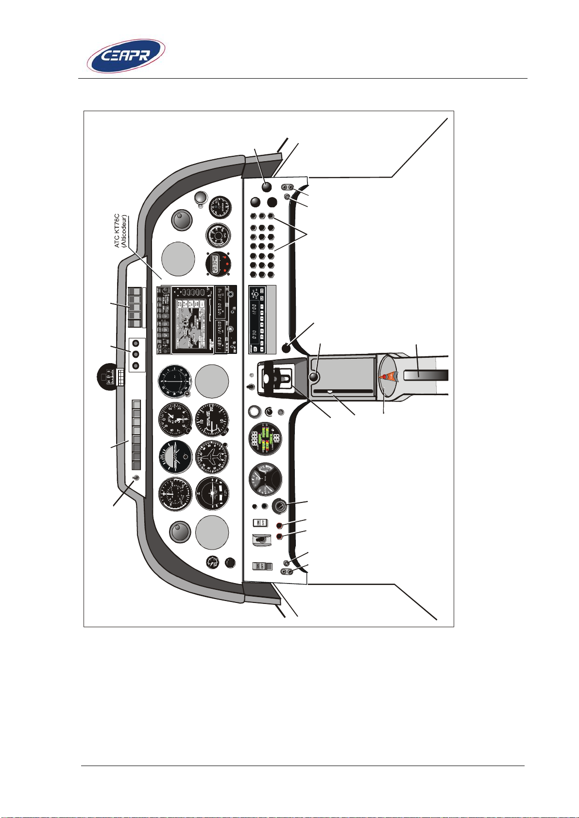
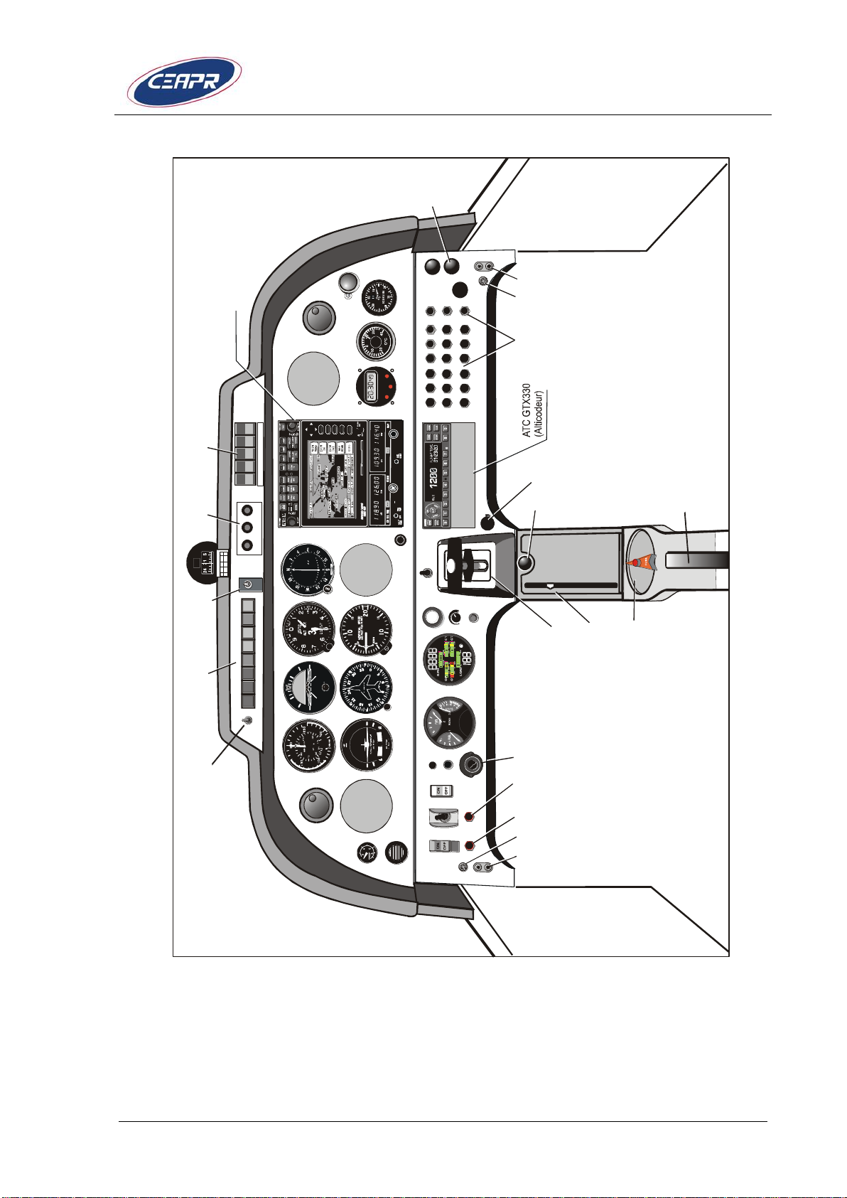
Figure 1-5 Instrument panel model #1
Note: The avionics instrument panel is shown as an example
only.
Issue 3 – July 2014 Page 1 - 11
Page 28
Supplement POH DR400/120D, DR400/140B,
DR400/180R, DR400/200R, DR400/RP
Instrument panel model #1
Pos
Fonction
Pos
Fonction
Pos
Fonction
1
Airspeed indicator
16
Warning lights
31
Fuel tank valve
2
Gyro horizon
17
Lights test &
day/night dimmer
switch
32
Elevator trim control
valve
3
Altimeter
18
Instrument panel
light
33
Elevator trim
position indicator
4
Turn coordinator
19
Safety switches:
landing light, taxi
light, strobe light,
navigation light,
pitot heat
34
Cabin heat /
windshield defrost
control
5
Directional gyro
20
Circuit breakers
35
Cabin heat
6
Rate of climb
indicator
21
Electric throttle
control
36
Instrument cut-off
7
Vacuum gauge
22
ANR jacks
37
VOR/LOC indicator
8
Engine indicator
CED-125
23
Mike and headset
jacks
38
Hourmeter
9
Parking brake
control knob
24
Fresh air vent
39
Outside air
temperature (OAT)
10
Westach triple
indicator
25
Battery safety
switch
40
Clock / chronometer
11
FADEC & alternator
excitation battery
26
Key starter
41
Stall warning
12
Electrical fuel pump
control
27
Glow light
42
Music jack
13
Alt. Induction air
28
FADEC test button
43
Auxiliary 12V
14
Force FADEC B
29
CED test / warning
switch off
44
Avionics Master
switch
15
Magnetic compass
30
CED-125 lighting
knob
45
Alternator relay
breaker
Table 1-2 Instrument panel #1 description
Page 1 - 12 Issue 3 – July 2014
Page 29
Supplement POH DR400/120D, DR400/140B,
DR400/180R, DR400/200R, DR400/RP
1
5
6
8
1
0
1
1
1
2
1
3
1
4
1
5
2
7
9
1
6
1
7
1
8
1
9
2
9
2
8
2
7
2
6
2
5
2
4
2
4
3
0
3
1
3
2
3
4
3
6
3
5
3
7
4
2
3
9
2
0
2
2
2
2
2
3
2
3
3
3
3
4
3
8
4
0
4
1
4
3
4
4
R
P
M
O
POT
2
3
6
5
0
1
4
0
b
a
r
C
L
O
A
D
%
t
r
/
m
i
n
2
3
0
0
6
0
1
0
5
1
2
0
C
C
CTG
T
1
0
0
O
F
F
L
R
B
O
T
H
S
T
2
0
707
0
707
0
706
0
4
0
4
0
2
0
2
1
4
5
5
C
H
R
O
N
O
M
E
T
E
R
L
C
-
6
R
S
T
S
T
/
S
P
M
O
D
E
S
E
T
A
D
V
4
6
4
7
G
M
A
3
4
0
K
M
D
1
5
0
K
X
1
5
5
-
3
8
E
L
T
A
U
T
O
M
A
N
U
A
L
4
6
Note: The avionics instrument panel is shown as an example
Figure 1-6 Instrument panel model #2
only.
Issue 3 – July 2014 Page 1 - 13
Page 30
Supplement POH DR400/120D, DR400/140B,
DR400/180R, DR400/200R, DR400/RP
Instrument panel model #2
Pos
Fonction
Pos
Fonction
Pos
Fonction
1
Airspeed indicator
17
Lights test &
day/night dimmer
switch
33
Elevator trim
position indicator
2
Gyro horizon
18
Instrument panel
light
34
Cabin heat /
windshield defrost
control
3
Altimeter
19
Safety switches:
landing light, taxi
light, strobe light,
navigation light,
pitot heat
35
Cabin heat
4
Turn coordinator
20
Circuit breakers
36
Interphone on board
5
Directional gyro
21
Electric throttle
control
37
VOR/LOC indicator
6
Rate of climb
indicator
22
ANR jacks
38
Hourmeter
7
Vacuum gauge
23
Mike and headset
jacks
39
Outside air
temperature (OAT)
8
Engine indicator
CED-125
24
Fresh air vent
40
Clock / chronometer
9
Parking brake
control knob
25
Battery safety
switch
41
Instrument cut-off
10
Westach triple
indicator
26
Key starter
42
Instrument cut-off
11
FADEC & alternator
excitation battery
27
Glow light
43
Auxiliary 12V
12
Electrical fuel pump
control
28
FADEC test button
44
Avionics Master
switch
13
Alt. Induction air
29
CED test / warning
switch off
45
Alternator relay
breaker
14
Force FADEC B
30
CED-125 lighting
knob
46
ELT control
15
Magnetic compass
31
Fuel tank valve
47
Music jack
16
Warning lights
32
Elevator trim control
valve
Table 1-3 Instrument panel #2 description
Page 1 - 14 Issue 3 – July 2014
Page 31

Supplement POH DR400/120D, DR400/140B,
DR400/180R, DR400/200R, DR400/RP
1
5
6
1
2
1
1
9
1
0
1
3
1
5
2
8
2
7
2
2
2
7
2
6
2
9
3
0
2
0
1
8
1
7
1
6
8
3
7
3
7
1
9
2
5
2
3
3
3
4
3
3
2
4
2
3
4
3
6
4
7
4
7
4
8
4
8
2
4
3
4
4
4
4
6
4
0
R
P
M
O
P
O
T
2
3
6
5
0
1
4
0
b
a
r
C
L
O
A
D
%
t
r
/
m
i
n
2
3
0
0
6
0
1
0
5
1
2
0
C
C
CTG
T
1
0
0
O
F
F
L
R
B
O
T
H
S
T
2
0
707
0
707
0
706
0
4
0
4
0
2
0
2
1
1
4
5
C
H
R
O
N
O
M
E
T
E
R
L
C
-
6
R
S
T
S
T
/
S
P
M
O
D
E
S
E
T
A
D
V
G
M
A
3
4
0
K
M
D
1
5
0
K
X
1
5
5
-
3
8
O
A
T
°
c
i
s
e
i
3
5
4
5
4
1
4
9
G
T
X
3
3
0
Note: The avionics instrument panel is shown as an example
only.
Figure 1-7 Instrument panel model #3
Issue 3 – July 2014 Page 1 - 15
Page 32

Supplement POH DR400/120D, DR400/140B,
DR400/180R, DR400/200R, DR400/RP
Instrument panel model #3
Pos
Fonction
Pos
Fonction
Pos
Fonction
1
Airspeed indicator
17
Glow light
34
Clock / chronometer
2
Gyro horizon
18
FADEC test button
35
Hourmeter
3
Altimeter
19
CED-125 lighting
knob
36
Circuit breakers
4
Turn coordinator
20
CED test / warning
switch off
37
Fresh air vent
5
Directional gyro
21
Electric throttle
control
40
Avionics Master
switch
6
Rate of climb
indicator
22
Parking brake
control knob
41
Avionics circuit
breakers
7
Vacuum gauge
23
Elevator trim control
42
VOR/LOC indicator
8
Battery safety
switch
24
Elevator trim
position indicator
43
ELT (optional)
9
FADEC & alternator
excitation battery
25
Fuel tank valve
44
Instrument cut-off
10
Electrical fuel pump
control
26
Lights test &
day/night dimmer
switch
45
Instrument cut-off
11
Westach quad
indicator
27
Warning lights
46
Auxiliary 12V
12
Engine indicator
CED-125
28
Magnetic compass
47
ANR jacks
13
Alt. Induction air
29
Instrument panel
light
48
Mike and headset
jacks
14
Alternator relay
breaker
30
Safety switches:
landing light, taxi
light, strobe light,
navigation light,
pitot heat
49
Music jack
15
Force FADEC B
32
Cabin heat
56
Transfer valve
control (optional)
16
Key starter
33
Cabin heat /
windshield defrost
control
57
Tank fuel T°C &
level display select
push-button
(optional)
Table 1-4 Instrument panel #3 description
Page 1 - 16 Issue 3 – July 2014
Page 33

Supplement POH DR400/120D, DR400/140B,
DR400/180R, DR400/200R, DR400/RP
1
5
6
1
2
1
1
9
1
0
1
3
1
5
2
8
2
7
2
2
2
7
2
6
2
9
3
0
2
0
1
8
1
7
1
6
8
3
7
3
7
1
9
2
5
2
3
3
3
4
3
3
2
4
2
3
4
3
6
4
7
4
7
4
8
4
8
2
4
3
4
4
4
4
6
4
0
R
P
M
O
P
O
T
2
3
6
5
0
1
4
0
b
a
r
C
L
O
A
D
%
t
r
/
m
i
n
2
3
0
0
6
0
1
0
5
1
2
0
C
C
CTG
T
1
0
0
O
F
F
L
R
B
O
T
H
S
T
2
0
707
07070
706
0
4
0
4
0
2
0
2
1
3
1
1
4
5
C
H
R
O
N
O
M
E
T
E
R
L
C
-
6
R
S
T
S
T
/
S
P
M
O
D
E
S
E
T
A
D
V
G
M
A
3
4
0
K
M
D
1
5
0
K
X
1
5
5
-
3
8
O
A
T
°
c
i
s
e
i
3
5
4
5
4
1
4
9
G
T
X
3
3
0
Note: The avionics instrument panel is shown as an example
Figure 1-8 Instrument panel model #4
only.
Issue 3 – July 2014 Page 1 - 17
Page 34

Supplement POH DR400/120D, DR400/140B,
DR400/180R, DR400/200R, DR400/RP
Instrument panel model #4
Pos
Fonction
Pos
Fonction
Pos
Fonction
1
Airspeed indicator
17
Glow light
33
Cabin heat /
windshield defrost
control
2
Gyro horizon
18
FADEC test button
34
Clock / chronometer
3
Altimeter
19
CED-125 lighting
knob
35
Hourmeter
4
Turn coordinator
20
CED test / warning
switch off
36
Circuit breakers
5
Directional gyro
21
Electrical throttle
control
37
Fresh air vent
6
Rate of climb
indicator
22
Parking brake
control knob
40
Avionics Master
switch
7
Vacuum gauge
23
Elevator trim control
41
Avionics circuit
breakers
8
Battery safety
switch
24
Elevator trim
position indicator
42
VOR/LOC indicator
9
FADEC & alternator
excitation battery
25
Fuel tank valve
43
ELT (optional)
10
Electrical fuel pump
control
26
Lights test &
day/night dimmer
switch
44
Instrument cut-off
11
Westach quad
indicator
27
Warning lights
45
Instrument cut-off
12
Engine indicator
CED-125
28
Magnetic compass
46
Auxiliary 12V
13
Alt. Induction air
29
Instrument panel
light
47
ANR jacks
14
Alternator relay
breaker
30
Safety switches:
landing light, taxi
light, strobe light,
navigation light,
pitot heat
48
Mike and headset
jacks
15
Force FADEC B
31
Optional tank fuel
T°C qty display
select.
49
Music jack
Table 1-5 Instrument panel #4 description
Page 1 - 18 Issue 3 – July 2014
Page 35

Supplement POH DR400/120D, DR400/140B,
DR400/180R, DR400/200R, DR400/RP
”Three-display“ and “four-display“ instruments
Example Of the Westach triple
indicator installed on models #1
and #2
Compact Engine Display CED-125
Example of the Westach quad
indicator installed on model #3
Figure 1-4 CED-125 detail
Issue 3 – July 2014 Page 1 - 19
Page 36

Supplement POH DR400/120D, DR400/140B,
DR400/180R, DR400/200R, DR400/RP
2
3
4
5
1
1
1
1
6
9
10
1
7
7
8
8
HEATING AND VENTILATION
1 Fresh Air Intake 2 Heat Exchanger
3 Warm Air Distribution Box 4 Warm Air Distribution Box
5 Forward / Aft Selection 6 Defrost / Heating Selection Box
7 Defrost Jet 8 Forward Heating
9 Aft Heating 10 Heating Controls
Figure 1-5 Heating and Ventilation
Page 1 - 20 Issue 3 – July 2014
Page 37

Supplement POH DR400/120D, DR400/140B,
DR400/180R, DR400/200R, DR400/RP
Heating Control Settings
Function
Pulled
Pushed
Control 0
- Button Lock
Heat ON/OFF
ON
OFF
Control 1
Heating ON/OFF
ON
OFF
Control 2
Defrost / Heating
FRONT
HEATING
WINDSHIELD
DEFROST
Control 3
Front / Rear select.
REAR
FRONT
Table 1-6 Heating Control Settings
Figure 1-6 Heat Control Placard, Right Cabin Side Wall
This STC installation has a fourth control (Control 0 in table above). It
must be OFF (Push) when cabin heat is not required (hot outside air
temperature)
Issue 3 – July 2014 Page 1 - 21
Page 38

Supplement POH DR400/120D, DR400/140B,
DR400/180R, DR400/200R, DR400/RP
Page 1 - 22 Issue 3 – July 2014
Page 39

Supplement POH DR400/120D, DR400/140B,
DR400/180R, DR400/200R, DR400/RP
AIRSPEED LIMITATIONS
km/h
kt
Vne, never exceed
270
146
Vno, normal operation
260
140
Va, maneuvering speed
215
116
Vfe, flaps extended limit speed
170
92
AIRSPEED INDICATOR MARKINGS
km/h
kt
Red line (never exceed)
Vne
270
146
Yellow arc (operate with caution
and only in "smooth air")
Vno-Vne
260 - 270
140 - 146
Green arc (normal operating
range)
Vs1-Vno
99 - 260
53 - 140
White arc
Vso-Vfe
87 - 170
47 - 92
APPROVED OPERATION
Table 2-1 Airspeed Limitations
SECTION 2
LIMITATIONS
Table 2-2 Airspeed Indicator Markings
MAXIMUM ALTITUDE
The DR400 with TAE 125-01 or TAE 125-02-99 engine installation has
been qualified up to 16.500 ft.
Issue 3 – July 2014 Page 2 - 1
Page 40

Supplement POH DR400/120D, DR400/140B,
DR400/180R, DR400/200R, DR400/RP
Cat. “U“
Cat. “N“
On Take off
2006 lb (910 kg)
2161 lb (980 kg)
On Landing
2006 lb (910 kg)
2161 lb (980 kg)
FLIGHT LOAD FACTOR LIMITS AT MAXIMUM WEIGHT
(2006 lb) 910 kg (category “U“):
Flaps up ............................................................ n between -2.2 and +4.4
Flaps down .................................................................................... n = +2
(2161 lb) 980 kg (category "N"):
Flaps up ............................................................ n between -1.9 and -3.8
Flaps down ................................................................................... n = + 2
CAUTION: Avoid extended negative g-loads duration.
Extended negative g-loads can cause propeller control
and engine problems.
Note: The load factor limits for the engine must
also be observed. Refer to the Operation & Maintenance
Manual for the engine.
MAXIMUM AUTHORIZED WEIGHTS
Table 2-3 Maximum Authorized Weights
WEIGHT AND BALANCE
Levelling ........................................................... upper fuselage longeron
Datum .........................................wing leading edge, rectangular section
Reference Chord ............................................................ (67.3 in) 1.71 m
Page 2 - 2 Issue 3 – July 2014
Page 41

Supplement POH DR400/120D, DR400/140B,
DR400/180R, DR400/200R, DR400/RP
Weight
kg (lb)
Arm
m (in)
Front Seats
2 x 77
(2 x 170)
0.36 - 0.46
(14 - 18)
Rear Seats (*)
2 x 77
(2 x 170)
1.19
(47)
Fuel, main fuselage tank
88
(194)
1.12
(44)
Baggage (**)
40
(88)
1.9
(75)
LOAD PLANNING
(Refer also to weight and balance chart, section 6)
The weight of the engine oil, as well as the unusable fuel must be
included in the empty weight of the aircraft.
Table 2-4 Load Planning
* The carriage on the rear seats of more than two passengers (whose
total weight remain below or equal to the maximum indicated) is
authorized, provided that passenger seat belts are installed for each
passenger and that weight and balance are kept within the authorized
limits.
** Within the authorized weight and balance limits.
ENGINE OPERATING LIMITS
Engine manufacturer ........................................... Technify Motors GmbH
Engine model .......................................... TAE 125-01 or TAE 125-02-99
Takeoff and max. continuous power .............................. 99 kw (135 HP)
Takeoff and max. continuous RPM ................................................. 2300
Note: In the absence of any other explicit
statements, all of the information on RPM in this
supplement to the Pilot´s Operating Handbook are
propeller RPM.
Issue 3 – July 2014 Page 2 - 3
Page 42

Supplement POH DR400/120D, DR400/140B,
DR400/180R, DR400/200R, DR400/RP
Engine operating limits for takeoff and continuous operation
▲ WARNING: It is not allowed to start the engine outside of these
temperature limits.
Note: The operating limit temperature is a
temperature limit below which the engine may be started,
but not operated at the takeoff RPM. The warm-up RPM
to be selected can be found in Section 4 of this
supplement.
Oil temperature:
Minimum engine starting temperature: ........................................ -32 °C
Minimum operating limit temperature: .............................................50 °C
Maximum operating limit temperature: ..........................................140 °C
Coolant temperature:
Minimum engine starting temperature: ........................................ -32 °C
Minimum operating limit temperature: .............................................60 °C
Maximum operating limit temperature: ..........................................105 °C
Gearbox temperature:
Minimum operating limit temperature: ........................................... -30 °C
Maximum operating limit temperature: ..........................................120 °C
Oil pressure:
Minimum oil pressure ................................................................... 1.2 bar
Minimum oil pressure (at take-off power)..................................... 2.3 bar
Minimum oil pressure in flight ...................................................... 2.3 bar
Maximum oil pressure .................................................................. 6.0 bar
Maximum oil pressure (cold start <20 sec.) ................................. 6.5 bar
Maximum oil consumption ............................................................. 0.1 l/h
Page 2 - 4 Issue 3 – July 2014
Page 43

Supplement POH DR400/120D, DR400/140B,
DR400/180R, DR400/200R, DR400/RP
Fuel
Minimum permissible fuel
temperature in the fuel
tank before takeoff
Minimum permissible fuel
temperature in the fuel
tank during the flight
Jet A-1, JET A,
Fuel No.3 JP-8,
JP-8+100, TS-1
- 30°C
- 35°C
Diesel
Greater than 0°C
- 5°C
Minimum fuel temperature limits in the fuel tanks:
Table 2-5 Min. Fuel Temperature Limits in the fuel tank
▲ WARNING: The following applies to Diesel and Jet A-1 mixtures in
the tank:
As soon as the proportion of Diesel in the tank is more
than 10%, the fuel temperature limits for Diesel operation
must be observed. If there is uncertainty about which fuel
is in the tank, the assumption should be made that it is
Diesel.
Issue 3 – July 2014 Page 2 - 5
Page 44

Supplement POH DR400/120D, DR400/140B,
DR400/180R, DR400/200R, DR400/RP
Instrument
Red
Range
Amber
Range
Green
Range
Amber
Range
Red
Range
Tachometer
[rpm]
-
-
0-2300
-
> 2300
Oil Pressure
[bar]
0-1.1
1.2-2.2
2.3-5.2
5.3-6.0
> 6.0
Coolant
temperature [°C]
< -32
-32...
+59
60-100
101-
105
> 105
Oil Temperature
[°C]
< -32
-32...
+49
50-124
125-
140
> 140
Gearbox
Temperature [°C]
-
-
< 115
115-
120
> 120
Load
[%]
-
-
0-100
-
-
ENGINE INSTRUMENT MARKINGS
The engine data of the TAE 125 installation to be monitored are
integrated in the combined engine instrument CED-125. The ranges of
the individual engine monitoring parameters are shown in the following
table.
Table 2-6 Markings of the Engine Instruments
Note: If an engine reading is in the yellow or red
range, the "Caution" lamp is activated. It only
extinguishes when the "CED-Test / confirm" button is
pressed. If this test button is pressed longer than one
second, a self-test of the instrument is initiated.
GROUNDING (EARTHING) BEFORE AND DURING FUELING
Use the engine exhaust pipe for draining static charge.
Page 2 - 6 Issue 3 – July 2014
Page 45

Supplement POH DR400/120D, DR400/140B,
DR400/180R, DR400/200R, DR400/RP
PERMISSIBLE FUEL GRADES
CAUTION: Using non-approved fuels and additives
can lead to dangerous engine malfunctions.
Fuel: ..................................................................... JET A-1 (ASTM 1655)
Alternative: ............................................................. Diesel (DIN EN 590)
Fuel additive for Diesel: .............. Liqui Moly “Diesel Fliess Fit” No. 5130
..................................... JP-8 (MIL-DTL-83133E)
............................. JP-8+100 (MIL-DTL-83133E)
................................. Fuel No.3 (GB 6537-2006)
Only TAE 125-02-99 (C2.0):
...................................... TS-1 (GOST 10227-86)
.................. TS-1 (GSTU 320.00149943.011-99)
MAXIMUM FUEL QUANTITIES
Standard tank:
Total capacity ......................................... 110 l / 29 US gal / 24.2 imp gal
Total usable fuel ..................................... 109 l / 28.7 US gal / 24 imp gal
Total unusable fuel .................................. 1 l / 0.26 US gal / 0.22 imp gal
Optional extended range tank (JET A-1 fuel only)
The total fuel capacity can be increased to 160 l / 35.2 imp gal / 42.24
US gal (159 l / 35 imp gal / 42 US gal usable) by installing an optional
fuel tank of 50 l / 11 imp gal / 13.2 US gal, which flows into the main tank
on command, most safely when the main tank can receive 50 liters. The
fuel level in the optional tank may be displayed on the instrument panel
fuel gauge indicator by pressing on the push-button switch.
Issue 3 – July 2014 Page 2 - 7
Page 46

Supplement POH DR400/120D, DR400/140B,
DR400/180R, DR400/200R, DR400/RP
PERMISSIBLE OIL GRADES
CAUTION: Use approved oil with exact designation only!
Engine oil: ........................................................ AeroShell Oil Diesel Ultra
......................................................... Shell Helix Ultra 5W-30
......................................................... Shell Helix Ultra 5W-40
.................................................AeroShell Oil Diesel 10W-40
Gearbox oil: .......................................... Shell Spirax S6 GXME 75W-80
.................................................. Shell Spirax S4 G 75W-90
............................... Shell Getriebeöl EP 75W-90 API GL-4
...................................................... Shell Spirax EP 75W-90
.......................................... Shell Spirax GSX 75W-80 GL-4
PERMISSIBLE COOLING LIQUID
Coolant: ............................ Water/Radiator Protection at a ratio of 50:50
Radiator Protection: .......................... BASF Glysantin Protect Plus/G48
..................................... Mobil Antifreeze Extra/G48
.................................... ESSO Antifreeze Extra/G48
........... Comma Xstream Green - Concentrate/G48
............................................... Zerex Glysantin G48
LOAD LIMITS
No change
OPERATIONAL LIMITATIONS IN THE “U” CATEGORY
CAUTION: Intentionally initiating negative G maneuvers is
prohibited!
Refer to original Pilot‘s Operating Handbook.
Intentionally initiating spins and negative G maneuvers is prohibited.
Page 2 - 8 Issue 3 – July 2014
Page 47

Supplement POH DR400/120D, DR400/140B,
DR400/180R, DR400/200R, DR400/RP
JET A1 (ASTM 1655)
DIESEL (EN590)
24.2 imp / 29 US Gal
110litres
JET A1 (ASTM 1655)
ONLY
11 imp / 13.2 US Gal
50litres
HUILE DR 400/135 CDI
OIL DR 400/CDI
PLACARDS
Figure 2-1 Near the Fuel Tank Caps: 110 liters JET/Diesel Fuel
Figure 2-2 Optional Extended Range Tank
or
Figure 2-3 On the oil funnel or at the engine cowling access door
Issue 3 – July 2014 Page 2 - 9
Page 48

Supplement POH DR400/120D, DR400/140B,
DR400/180R, DR400/200R, DR400/RP
FUEL
E = 0
¼ = 25
½ = 50
¾ = 75
F = 100
( LITERS )
TE ST / AC K
ENGINE
CAUTION
ALT
FUEL
LOW
LEVEL
FADECAFADECBFLAPS
DOWN
PITOT
HEATING
COOLANT
LEVEL
PRISE DE
PARC
AUSSENBORD
STROMANSCHLUSS
EXTERNAL
POWER
12 V
Figure 2-4 Near the CED
Figure 2-5 Near their respective gauges or switches
Figure 2-6 Annunciator Lights at the Top of the Instrument Panel
Figure 2-7 If installed, at the access door to the external power receptacle behind the wing on the aircraft's right side.
Note: The receptacle has "one way only" feature for polarity
protection.
Page 2 - 10 Issue 3 – July 2014
Page 49

Supplement POH DR400/120D, DR400/140B,
DR400/180R, DR400/200R, DR400/RP
FUEL T(°C)
indicated
MAIN TANK
OPT. TANK
FUEL QTY (litres)
Figure 2-8
If optional extended range fuel tank is installed, placard must be placed
near to the fuel gauge.
or
Figure 2-9
If optional extended range fuel tank is installed, placard must be placed
near the fuel transfer control.
Issue 3 – July 2014 Page 2 - 11
Page 50

Page 51

Supplement POH DR400/120D, DR400/140B,
DR400/180R, DR400/200R, DR400/RP
SECTION 3
EMERGENCY PROCEDURES
INDEX OF CHECKLISTS
ENGINE FAILURE OR LOSS OF POWER ........................................... 3-2
During takeoff roll ................................................................................... 3-2
Immediately after takeoff ....................................................................... 3-2
During flight ............................................................................................ 3-3
LANDING WITHOUT ENGINE POWER ............................................... 3-4
Restart after engine failure .................................................................... 3-5
FADEC malfunction in flight ................................................................... 3-6
ENGINE SHUT-DOWN IN FLIGHT ....................................................... 3-9
FIRE .....................................................................................................3-10
Engine fire on the ground, during starting ...........................................3-10
Engine fire in flight ..............................................................................3-10
Electrical fire.........................................................................................3-11
ROUGH ENGINE OPERATION ..........................................................3-12
Oil pressure too low .............................................................................3-12
Oil temperature too high ......................................................................3-13
Coolant temperature too high ..............................................................3-13
“Cool level” light illuminates .................................................................3-14
Gearbox temperature too high .............................................................3-14
Fuel temperature too low .....................................................................3-14
Propeller RPM too high ........................................................................3-15
Fluctuations in propeller RPM ..............................................................3-15
ICING ...................................................................................................3-16
ELECTRICAL POWER SUPPLY MALFUNCTION .............................3-17
If the “ALT” light is lit or the ammeter shows battery discharge during
normal engine operation for more than 5 minutes ...............................3-18
INADVERTENT SPIN ..........................................................................3-19
LOSS OF ELEVATOR CONTROL ......................................................3-19
Issue 3 – July 2014 Page 3 - 1
Page 52

Supplement POH DR400/120D, DR400/140B,
DR400/180R, DR400/200R, DR400/RP
ENGINE FAILURE OR LOSS OF POWER
During takeoff roll
1) Thrust Lever .............................................................................. IDLE
2) Apply brakes and hold direction. Avoid obstructions.
3) Engine Master switch ................................................................ OFF
4) Battery and ALT CB .................................................................. OFF
5) Fuel selector.............................................................................. OFF
6) Emergency ground egress ............................................. As required
Immediately after takeoff
1) Establish glide
Speed (flaps retracted) ..................................... (78 KIAS) 144 km/h
Speed (flaps T/O position) ............................... (75 KIAS) 139 km/h
2) Land straight ahead, with only small direction changes to avoid
obstructions.
3) If complete engine failure:
FADEC A/B Switch .............................................................. Force B
4) Battery and ALT switch .................................................... Check ON
When landing inevitable:
5) Engine Master ........................................................................... OFF
6) Battery and ALT CB .................................................................. OFF
7) Fuel selector.............................................................................. OFF
8) Wing flaps ........................................ T/O or Landing recommended
9) Touch down with minimum speed
10) When aircraft has stopped ..................... Emergency ground egress
▲ WARNING: Never try to turn back to the runway, as altitude just after
takeoff is seldom sufficient.
Page 3 - 2 Issue 3 – July 2014
Page 53

Supplement POH DR400/120D, DR400/140B,
DR400/180R, DR400/200R, DR400/RP
During flight
1) Establish glide:
Flaps retracted .................................................. (78 KIAS) 144 km/h
(In these conditions, without wind, the aircraft covers approx. 8 times
its height above ground). Locate suitable field.
If altitude is sufficient to restart:
2) Electric fuel pump ........................................................................ ON
3) FADEC A/B switch .............................................................. Force B
if this doesn't improve engine operation, return switch to "Auto"
4) If no restart ......................... Reset Engine Master (OFF then to ON)
5) Battery and ALT CB ......................................................... Check ON
6) Engine and fuel level gauges /alarm panel
................................................................. Check for cause of failure
7) FADEC A, B circuit breakers ........................................... Check ON
8) In case the tank has been run to empty with still some fuel available
in the auxiliary tank
(if so equipped) ................................. Open aux. tank transfer valve
If the propeller does not turn:
9) Starter .......................................................................................... ON
The propeller will normally continue to turn as long as the airspeed
is above 120 km/h (65 KIAS). Should the propeller stop at airspeed
of more than 120 km/h or more, the reason for this should be found
out before attempting a restart.
If it is obvious that the engine or propeller is blocked, do not use the
Starter.
If power is not restored, prepare for "landing without engine power".
If the tank has been run to empty, both FADEC lights will be flashing.
▲ WARNING: The engine high pressure pump must be checked before
the next flight.
Issue 3 – July 2014 Page 3 - 3
Page 54

Supplement POH DR400/120D, DR400/140B,
DR400/180R, DR400/200R, DR400/RP
LANDING WITHOUT ENGINE POWER
Look for a suitable landing area:
1) Airspeed .................................... 144 km/h (78 KIAS) flaps retracted
139 km/h (75 KIAS) flaps T/O
2) Seat belts and harness ............................................................. Tight
Before landing:
3) Electric pump ............................................................................ OFF
4) Fuel selector.............................................................................. OFF
5) Engine master switch ................................................................ OFF
6) Battery + Alternator switches .................................................... OFF
7) Flaps, when field can easily be reached: ................. T/O or Landing
8) Touch down with minimum speed
9) Brakes ............................................................................ As required
10) When aircraft has stopped ..................... Emergency ground egress
Page 3 - 4 Issue 3 – July 2014
Page 55

Supplement POH DR400/120D, DR400/140B,
DR400/180R, DR400/200R, DR400/RP
Restart after engine failure
Note: If altitude permits and a restart is possible.
1) Airspeed ................................. Flaps retracted (78 KIAS) 144 km/h
[max. 100 KIAS, min. 70 KIAS]
2) Reliable restart altitude ......................................... Below 13 000 ft
3) Battery and ALT CB ....................................................... Check ON
4) Fuel selector ......................................................................... OPEN
5) Electric fuel pump ...................................................................... ON
6) Power lever .................................................................. max. power
7) Engine master switch............................................... OFF, then ON
if the propeller does not turn, the starter may be used.
CAUTION: If the propeller is jammed, operate the starter briefly.
If it is obvious that the engine or propeller is blocked
(speed has been maintained above 70 KIAS all the time),
do not use the starter.
8) Engine parameters ............................................................... Check
9) Power lever, once engine runs
smoothly at idle ..................................................................... Adjust
10) Engine operation ...................................... Check available power /
engine parameters
Note: If the engine still does not start, prepare for
"Landing without Engine Power". Refer to page 3-4.
Issue 3 – July 2014 Page 3 - 5
Page 56

Supplement POH DR400/120D, DR400/140B,
DR400/180R, DR400/200R, DR400/RP
FADEC malfunction in flight
Note: The FADEC consists of two components
that are independent of each other: FADEC A and
FADEC B. In case of malfunctions in the active FADEC,
it automatically switches to the other.
a) One FADEC Lamp is flashing
(1) Press FADEC-Test knob at least 2 seconds
(2) FADEC Lamp extinguished (LOW category warning):
a) Continue flight normally
b) Inform service center after landing.
(3) FADEC Lamp steady illuminated (HIGH category warning):
a) Observe the other FADEC lamp,
b) Land as soon as practical,
c) Airspeed should be below 100 KIAS (185 km/h),
d) Inform service center after landing.
Page 3 - 6 Issue 3 – July 2014
Page 57

Supplement POH DR400/120D, DR400/140B,
DR400/180R, DR400/200R, DR400/RP
b) Both FADEC Lamps are flashing
Note: The load display may not correspond to the current
value.
(1) Press FADEC-Test knob at least 2 seconds (refer to section 1
“FADEC Reset”)
(2) FADEC Lamps extinguished (LOW):
a) Continue flight normally,
b) Inform service center after landing.
(3) FADEC Lamps steady illuminated (HIGH):
a) Check the available engine power,
b) Expect engine failure.
c) Flight can be continued, however the pilot should
i) Select an airspeed below 100 KIAS (185 km/h)
ii) Land as soon as possible
iii) Be prepared for an emergency landing.
(4) Inform service center after landing.
Issue 3 – July 2014 Page 3 - 7
Page 58

Supplement POH DR400/120D, DR400/140B,
DR400/180R, DR400/200R, DR400/RP
c) Abnormal engine behavior
Note: The FADEC system normally switches
automatically between FADEC A and B in case of
malfunction, in order to select the "healthiest"
component.
If this automatic switching doesn't work, it is possible to
manually force the system to switch to FADEC B only,
and check for improvement in engine behavior.
1) Maximum airspeed ........................................ (100 KIAS) 185 km/h
2) "FADEC A/B" switch........................................................FORCE B
3) If no engine operation improvement ......... Return switch to "Auto"
Note: The switching from one FADEC to the other
one is usually accompanied by a short RPM fluctuation.
Page 3 - 8 Issue 3 – July 2014
Page 59

Supplement POH DR400/120D, DR400/140B,
DR400/180R, DR400/200R, DR400/RP
ENGINE SHUT-DOWN IN FLIGHT
Note: If it is necessary to shut down the engine in
flight (for instance, abnormal engine behavior does not
allow continued flight, fuel leak, fire, etc.):
1) Reduce speed .................................... Below (100 KIAS) 185 km/h
2) Engine master switch............................................................... OFF
3) Fuel selector valve ................................................................... OFF
4) Electric fuel pump .................................................... OFF (if in use)
5) If the propeller has also to be stopped (for instance, due to
excessive vibrations) ..................................... Reduce airspeed to
60 - 65 KIAS, flaps T/O
6) When the propeller is stopped ......................... Continue to glide at
70 - 75 KIAS, flaps T/O
Issue 3 – July 2014 Page 3 - 9
Page 60

Supplement POH DR400/120D, DR400/140B,
DR400/180R, DR400/200R, DR400/RP
FIRE
Engine fire on the ground, during starting
1) Engine master switch .............................................................. OFF
2) Fuel selector ............................................................................ OFF
3) Electric fuel pump.................................................................... OFF
4) Battery + alternator switch ...................................................... OFF
5) Emergency ground egress ........................................... As required
Extinguish the flames with a fire extinguisher, wool blankets or sand.
Have fire damage thoroughly examined and appropriate repairs made
before the next flight.
Engine fire in flight
1) Power lever ...................................................................... Reduce
2) Reduce speed .................................. Below (100 KIAS) 185 km/h
3) Engine master switch ............................................................ OFF
4) Fuel selector .......................................................................... OFF
5) Electric fuel pump .................................................. OFF (if in use)
6) Battery + alternator switch (after radio calls) ........................ OFF
7) Cabin heat ............................................................................. OFF
8) Glide speed ................................................... (78 KIAS) 144 km/h
9) Adjust cabin ventilation for lowest smoke in the cabin
10) Fire extinguisher (if available) ............................. Use as required
Note: Proceed with "landing without engine power".
Page 3 - 10 Issue 3 – July 2014
Page 61

Supplement POH DR400/120D, DR400/140B,
DR400/180R, DR400/200R, DR400/RP
Electrical fire
Note: In case of an electrical fire (smell of fumes
indicating wire insulation burning):
1) All electrical equipment and c (after brief call) ....................... OFF
leave Alternator, Battery and Engine Master ON
2) Cabin ventilation .................................................................... OFF
3) Cabin heat .............................................................................. OFF
4) Fire extinguisher (if available) ............................. Use as required
▲ WARNING: After the fire extinguisher has been used, make sure that
the fire is extinguished before exterior air is used to
remove smoke from the cabin
5) If there is evidence of continued electrical fire, consider turning
OFF Battery and Alternator
▲ WARNING: If both Battery and Alternator are turned OFF, the engine
will continue to operate using the FADEC backup battery
for limited time (TAE 125-02-99 installation).
- Perform emergency landing. Refer to page 3-4.
- do not switch the “FORCE-B” switch, this will shut down
the engine!
If the fire has been extinguished:
6) Cabin ventilation ...................................................................... ON
7) Check circuit breakers, do not reset if open
8) Avionics Master Switch ............................................................ ON
9) Turn ON only electrical equipment required to continue flight
depending on the situation and land as soon as practical.
Do only switch ON one at a time, with delay after each.
Issue 3 – July 2014 Page 3 - 11
Page 62

Supplement POH DR400/120D, DR400/140B,
DR400/180R, DR400/200R, DR400/RP
ROUGH ENGINE OPERATION
Oil pressure too low (< 2.3 bar in cruise or <1.2 bar at idle power)
(1) Reduce power as quickly as possible
(2) Check oil temperature: If the oil temperature is high or near operating
limits,
i) Land as soon as possible
ii) Be prepared for an emergency landing
iii) Expect engine failure
Note: During warm-weather operation or longer
climb outs at low airspeed engine temperatures could
rise into the amber range and trigger the "Caution" light.
This warning allows the pilot to avoid overheating of the
engine as follows:
(3) Increase the climbing airspeed, reduce angle of climb
(4) Reduce power, if the engine temperatures approach the red area.
Page 3 - 12 Issue 3 – July 2014
Page 63

Supplement POH DR400/120D, DR400/140B,
DR400/180R, DR400/200R, DR400/RP
Oil temperature too high
(1) Increase airspeed and reduce power as quickly as possible
(2) Check oil pressure. If the oil pressure is lower than normal (<2.3 bar
in cruise or <1.2 bar at idle),
i) Land as soon as possible
ii) Be prepared for an emergency landing
iii) Expect engine failure
(3) If the oil pressure is in the normal range
i) Land as soon as practical
Note: During hot weather operation or prolonged
climbs at low airspeed, engine temperatures could rise
into the yellow range and trigger the caution light. This
warning allows the pilot to avoid overheating of the
engine as follows:
1. Increase the climbing airspeed
2. Reduce power if the engine temperature approaches
the red area.
Coolant temperature too high
1) Check coolant level light
2) Increase airspeed and reduce the power.
3) Check cabin heat ................................................................... OFF
If coolant level light is on, or an obvious malfunction is suspected
(because airspeed was maintained above Vy, non-hot weather
conditions, cabin heat OFF) or if this does not cause the coolant
temperature to drop,
i) Land as soon as practical
ii) Be prepared for an emergency landing
iii) Expect an engine failure
Issue 3 – July 2014 Page 3 - 13
Page 64

Supplement POH DR400/120D, DR400/140B,
DR400/180R, DR400/200R, DR400/RP
“Cool level” light illuminates
1) Increase airspeed and reduce the power
2) Cabin heat ............................................................................. OFF
3) Monitor coolant temperature
4) Monitor oil temperature
5) If coolant temperature and/or oil temperature are rising into amber
and towards red range:
i) Land as soon as practical
ii) Be prepared for an emergency landing
iii) Expect an engine failure
Gearbox temperature too high
1) Reduce power ............................................................. 55% - 75%
2) Land as soon as practical
Fuel temperature too low
1) Change to altitude with higher outside air temperature
2) If the fuel temperature remains too low:
i) land as soon as practical
Page 3 - 14 Issue 3 – July 2014
Page 65

Supplement POH DR400/120D, DR400/140B,
DR400/180R, DR400/200R, DR400/RP
Propeller RPM too high
Note: If propeller RPM above 2300 (red range):
1) Reduce power
2) Reduce airspeed below 100 KIAS (185 km/h) or as appropriate to
prevent propeller overspeed
3) Set power as required to maintain altitude and land as soon as
practical.
Note: If the propeller speed control fails, climb
flights can be performed at 120 km/h (65 KIAS) and a
power setting of 100%. In case of over speed the
FADEC will reduce the engine power at higher airspeeds
to avoid propeller speeds above 2500 rpm.
Fluctuations in propeller RPM
If the propeller RPM fluctuates by more than ± 100 RPM with a constant
power lever position:
1) Change the power setting and attempt to find a power setting
where the propeller RPM no longer fluctuates.
2) If unsuccessful power lever full forward at airspeed < 185 km/h
(100 KIAS) until propeller speed stabilizes
3) If normal operation is resumed, continue the flight
4) If problem continues, select a power setting where the propeller
RPM fluctuations are minimum. Fly at airspeed below 185 km/h
(100 KIAS) and land as soon as practical.
Issue 3 – July 2014 Page 3 - 15
Page 66

Supplement POH DR400/120D, DR400/140B,
DR400/180R, DR400/200R, DR400/RP
ICING
▲ WARNING: It is prohibited to fly in known icing conditions.
Icing has a very strong negative effect on the
aerodynamic characteristics of the aircraft. Stalling
speed increases.
Proceed as follows when inadvertently encountering icing:
1) Pitot heat switch ....................................................... ON (if installed)
If no pitot heat installed, expect airspeed indications to become
unreliable
2) Immediately leave the region in which the icing occurred. If possible
change the altitude to obtain an outside air temperature that is less
conductive to icing
3) Cabin heat / defrost ........................................................ As required
4) Alternate induction air ............................................................ OPEN
5) Increase power; make quick power changes from time to time to try
to clear ice from the propeller blades.
Plan to land at the nearest airfield. If the build-up of ice is extremely fast,
execute an off-airfield forced landing.
Note: A layer of 0.5 cm (0.2 in) on the leading
edge of the wing substantially increases the stalling
speed. If needed, use a higher than normal approach
speed: 145 km/h (78 KIAS). Do not use flaps.
Page 3 - 16 Issue 3 – July 2014
Page 67

Supplement POH DR400/120D, DR400/140B,
DR400/180R, DR400/200R, DR400/RP
ELECTRICAL POWER SUPPLY MALFUNCTION
Note: The TAE 125 requires an electrical power source for its
operation. If the alternator fails, the only power source
will be provided by the battery. The time the engine can
run on battery alone will depend on total electrical
consumption supported by the battery, i.e. the load of the
electrical equipment kept in use.
The pilot should turn off all non-essential items and
supply power only to equipment which is absolutely
necessary for continued flight depending upon the
situation.
If the FADEC back-up battery is installed (TAE 125-02-99 installation):
▲ WARNING: When both main battery and alternator have failed, the
engine will continue to operate using the FADEC backup
battery for limited time. In this case, all electrical
equipment will not operate:
- land immediately
- do not switch the “FORCE-B” switch, this will shut down
the engine!
The failure of the alternator is indicated by:
"ALT" light is ON
Voltmeter shows too low or too high voltage (red range)
Ammeter (if installed) shows battery discharge for more than
5 min
Issue 3 – July 2014 Page 3 - 17
Page 68

Supplement POH DR400/120D, DR400/140B,
DR400/180R, DR400/200R, DR400/RP
If the “ALT“ light is lit or the ammeter shows battery discharge
during normal engine operation for more than 5 minutes
1) Alternator circuit breaker .................................................. Check ON
CAUTION: If the FADEC was supplied by battery only
until this point, the RPM can momentarily drop, when the
alternator will be switched on. In any case: leave the
alternator switched ON!
2) Check "ALT" light and voltmeter indications
3) If normal operation has not resumed:
Alternator ................................................................................... OFF
4) Switch OFF all electrical equipment not essential for continuation of
flight
5) Land as soon as possible
Page 3 - 18 Issue 3 – July 2014
Page 69

Supplement POH DR400/120D, DR400/140B,
DR400/180R, DR400/200R, DR400/RP
INADVERTENT SPIN
Should a spin occur, apply the following procedure:
1) Power Lever ....................................................................... Idle (pull)
2) Rudder ..................................... Full opposite to direction of rotation
3) Elevator ................................................................................. Neutral
4) Ailerons ................................................................................ Neutral
5) Once the rotation is stopped, bring rudder to neutral position and
recover within flight limitations.
Note: If flaps are down when spin begins, retract
them immediately.
LOSS OF ELEVATOR CONTROL
No change, refer to original POH
Issue 3 – July 2014 Page 3 - 19
Page 70

Supplement POH DR400/120D, DR400/140B,
DR400/180R, DR400/200R, DR400/RP
Page 3 - 20 Issue 3 – July 2014
Page 71

Supplement POH DR400/120D, DR400/140B,
DR400/180R, DR400/200R, DR400/RP
SECTION 4
NORMAL PROCEDURES
NORMAL OPERATING SPEEDS
The speeds listed below are indicated airspeeds recommended for
normal operation of the aircraft.
These speeds are based on a standard aircraft, operated at max. takeoff weight, in standard atmosphere and at sea level. They may vary from
one aircraft to another depending on the equipment installed, the
conditions of the aircraft and of the engine, the atmospheric conditions
and the skills of the pilot.
Best rate of climb speed
Flaps in takeoff position (1st notch) ............................ (76 KIAS) 141 km/h
Flaps up ...................................................................... (78 KIAS) 144 km/h
Best angle of climb speed
Flaps in takeoff position (1st notch) ............................ (65 KIAS) 120 km/h
Flaps up ...................................................................... (65 KIAS) 120 km/h
Maximum operating speed in turbulent air
Flaps up .................................................................... (140 KIAS) 260 km/h
Maximum speed
Flaps in landing position (2nd notch) .......................... (92 KIAS) 170 km/h
Landing speed, final approach
Flaps in landing position (2nd notch) .......................... (62 KIAS) 115 km/h
Issue 3 – July 2014 Page 4 - 1
Page 72

Supplement POH DR400/120D, DR400/140B,
DR400/180R, DR400/200R, DR400/RP
PRE-FLIGHT INSPECTION
To be performed before each flight.
This inspection may be shortened for intermediate landings on route.
Figure 4-1 Pre-flight inspection
Page 4 - 2 Issue 3 – July 2014
Page 73

Supplement POH DR400/120D, DR400/140B,
DR400/180R, DR400/200R, DR400/RP
Master engine switch ...........................................................................OFF
Avionics master switch (if equipped) ...................................................OFF
Controls ............................................................................ Free and correct
Battery switch ........................................................................................ ON
▲ WARNING: When turning on the battery switch, using an external
power source, or pulling the propeller through by hand,
treat the propeller as if the Engine Master switch was on.
Flaps ................................................................................ Check operation
Fuel quantity................................................................................. Checked
Fuel temperature .......................................................................... Checked
Water level .................................................................................. Light OFF
Battery switch .......................................................................................OFF
Aircraft documents ....................................................................... On board
Baggage ........................................................................... Securely stowed
Check flight controls displacements, then make an aircraft walk around
inspection starting at the fuselage left side. See Figure 4-1.
(1)
a) Fuel filler cap .................................................... in place, secured
b) Static vent ..................................................... clean, unobstructed
c) Main tank drain valve ..................................................... actuated
d) Optional tank (when installed) drain valve ..................... actuated
Note: Left or right depending on airplane bank
attitude. Check for water, sediment and the right type of
fuel (Diesel or JET A-1 versus Avgas [should not be
blue!])
Issue 3 – July 2014 Page 4 - 3
Page 74

Supplement POH DR400/120D, DR400/140B,
DR400/180R, DR400/200R, DR400/RP
(2)
a) Horizontal stabilizer ...................................... Surface condition,
hinge wear in tolerance
b) Rudder ........................................ Check hinge wear in tolerance
(3)
a) Static vent .................................................... Clean, unobstructed
(4)
a) Flap and aileron ............................... Check condition and hinges
b) Wing tip and navigation lights (optional) ... Check condition
(5)
a) Stall warning ............................................ Clean, check actuation
b) Right main landing gear.......................... Check, oil cap secured,
Panel closed,
Normal shock absorber compression,
Tire inflated
(6)
a) Fuel drain valve ............................................................. Actuated
b) Oil level ......................... Checked, oil cap secured, panel closed
c) Exhaust pipe ........................................................................ Rigid
d) Engine cowl attachments................................................... Check
e) Propeller ............................................... Clean, in good condition
f) Propeller spinner ............................................................. No play
g) Air inlets ....................................................... Clean, unobstructed
h) Gear box oil level ............................................................... Check
Note: The oil has to cover at least half of the
inspection glass
Page 4 - 4 Issue 3 – July 2014
Page 75

Supplement POH DR400/120D, DR400/140B,
DR400/180R, DR400/200R, DR400/RP
(7)
a) Nose gear ............................. Check attachment and condition of
fairing, normal shock absorber compression, tire inflated, tow
bar removed
b) Canopy cleanliness ............................................................Check
(8)
a) Left main landing gear ............................. Check attachment and
condition of fairing,
normal shock absorber compression,
tire inflated
b) Pitot ............................................................. Clean, unobstructed
c) Lights (optional) ........................................................ Glass clean
(9)
a) Wing tip and navigation light (optional) .............. Check condition
b) Flap and aileron............................... Check condition and hinges
CABIN INTERIOR CHECK BEFORE START-UP
1) Canopy ............................................................... Closed and locked
2) Parking brake........................................................................ Locked
3) Front seats ....................................................... Adjusted and locked
4) Belts and harnesses ..................................... Adjusted and fastened
5) Flight controls .................... Free, without play or excessive friction,
correct action (check rudder during taxiing)
6) Elevator trim ................. Check travel, then return to takeoff position
7) Battery switch .............................................................................. ON
8) CED lights autotest ............................................................... Monitor
9) ALT CB ........................................................................................ ON
10) Alarm panel .......................... Test, set DAY / NIGHT as appropriate
Issue 3 – July 2014 Page 4 - 5
Page 76

Supplement POH DR400/120D, DR400/140B,
DR400/180R, DR400/200R, DR400/RP
11) Circuit breakers ........................................................................... ON
Note: The electronic engine control needs an
electrical power source for its operation. For normal
operation, battery switch and alternator circuit breaker
have to be ON. Separate switching is only allowed for
tests and in event of emergencies.
12) All electrical switches and avionics ........................................... OFF
CAUTION: The avionics power switch must be off
during engine start to prevent possible damage to
avionics.
STARTING THE ENGINE
1) Canopy .................................................................................. Closed
2) Strobe light .................................................................................. ON
3) Fuel level / fuel temperature ................................................. Check
4) Fuel selector.................................................... Check operation, ON
5) Alternate induction air ........................................................... Closed
6) Electric pump .............................................................................. ON
7) Thrust Lever .............................................................................. IDLE
8) Propeller area........................................................................... Clear
9) Master Engine switch ................................................................. ON,
10) FADEC lights.................................................................. Check OFF
11) Glow Control light ...................................................... Wait until OFF
12) Starter ......................................................................................... ON
Note: Release when engine starts, leave Thrust
Lever in idle position
CAUTION: It is not allowed to start up the engine using
external power!
Page 4 - 6 Issue 3 – July 2014
Page 77

Supplement POH DR400/120D, DR400/140B,
DR400/180R, DR400/200R, DR400/RP
13) Check ................................................... Oil pressure / Idle RPM 890
CAUTION: If after 3 seconds the minimum oil pressure
of 1 bar is not indicated, shut down the engine
immediately!
14) “Engine“ resp. “CED“ Caution light ............................. Acknowledge
15) ALT light ......................................................................... Check OFF
16) Ammeter (if installed) ................ Check for positive charging current
17) FADEC lights ................................................................. Check OFF
18) Vacuum gauge........................................................................ Check
AFTER ENGINE START
1) Electrical fuel pump ................................................................... OFF
If FADEC Backup battery installed (TAE 125-02-99 installation):
a) Alternator ..................................OFF, engine must operate normally
b) Battery ...................................................... OFF, for min. 10 seconds;
engine must operate normally, the red FADEC lamps must not be
illuminated
c) Battery .......................................................................................... ON
d) Alternator ..................................................................................... ON
▲ WARNING: It must be ensured that both battery and alternator are
ON!
2) Avionics power switch (if equipped) ............................................ ON
3) COM / NAV, navigation instruments .................................... ON, set
4) Altimeter ....................................................................................... Set
5) Horizon / Directional gyro ............................................................ Set
Issue 3 – July 2014 Page 4 - 7
Page 78

Supplement POH DR400/120D, DR400/140B,
DR400/180R, DR400/200R, DR400/RP
WARM UP
1) Cabin heat can be pulled to facilitate quicker coolant warming.
2) Let the engine warm up about 2 minutes at idle
3) Increase to not more than 1400 RPM until oil temperature minimum
50 °C, coolant temperature minimum 60 °C
(All CED LEDs....................................................................... green).
TAXIING
1) Parking brakes ...................................................................Unlocked
2) Brakes ........................................................................................ Test
3) Do not exceed 1400 RPM when CED shows yellow LED for oil and
coolant temperature
4) During taxi / turns:
a) Turn and bank indicator / Horizon (option) ........................ Check
b) Directional gyro (option) ................................... Check operation
c) Standby compass .............................................................. Check
BEFORE TAKEOFF
1) Parking brake ............................................................................. SET
2) Canopy ...................................................... CLOSED AND LOCKED
3) Flight controls ......................................................... Free and correct
4) Flight and navigation instruments ............................. Check and Set
5) Cabin heat ................................................................ Set as required
(OFF if heating is not desired)
6) Fuel selector valve ...................................................................... ON
7) Fuel quantity............................................... Verify sufficient for flight
8) Elevator trim ............................................................... Set for takeoff
Page 4 - 8 Issue 3 – July 2014
Page 79

Supplement POH DR400/120D, DR400/140B,
DR400/180R, DR400/200R, DR400/RP
9) (FADEC self-check:
a) Thrust Lever ......................................... IDLE (both FADEC lamps
should be OFF)
b) FADEC test button ............................... PRESS and HOLD button
for entire test
c) Both FADEC lamps ........................................ ON, RPM increases
Note: If the FADEC test does not start, verify if the
thrust lever is in IDLE position. If not, set to IDLE position
and try again to start FADEC test
▲ WARNING: If the FADEC lamps do not come on at this point, it
means that the test procedure has failed and takeoff
should not be attempted.
d) The FADEC automatically switches to B-component (only
FADEC B light is on).
e) The propeller control is excited, RPM decreases momentarily
f) The FADEC automatically switches to channel A (only FADEC A
light is ON)
g) The propeller control is excited, RPM decreases momentarily
h) FADEC A lamp goes off, RPM goes back to idle RPM, and the
test is completed.
i) FADEC test button ........................................................ RELEASE
▲ WARNING: If there are prolonged engine misfires or the engine
shuts down during the test, takeoff must not be
attempted.
Issue 3 – July 2014 Page 4 - 9
Page 80

Supplement POH DR400/120D, DR400/140B,
DR400/180R, DR400/200R, DR400/RP
▲ WARNING: The whole test procedure has to be performed without
any discrepancy. In case the engine shuts down or the
FADEC lamps are flashing, takeoff is PROHIBITED. This
applies even if the engine seems to run without failure
after the test.
Note: If the test button is released before the self-test is fully
completed, the FADEC immediately resumes normal
operation.
Note: While switching from one FADEC to
another, it is normal to hear and feel a momentary surge
in the engine.
10) Thrust Lever ........................................................ FULL FORWARD,
RPM must be stabilized
load display minimum 94%
RPM 2240 - 2300
Note: The power check should be performed at a
place which is free of debris to minimize risk of damage
to propeller or other parts.
11) Thrust Lever .............................................................................. IDLE
12) Engine instruments and Voltmeter ...................................... CHECK
13) Vacuum gauge ..................................................................... CHECK
14) Flaps .................................. Full down, then back to takeoff position
15) Electrical fuel pump ..................................................................... ON
16) Radios and avionics ............................................................. ON, set
17) Thrust Lever friction control ..................................... SET as desired
18) Brakes .............................................................................. RELEASE
19) CED ......................................................... CHECK all LEDs GREEN
Page 4 - 10 Issue 3 – July 2014
Page 81

Supplement POH DR400/120D, DR400/140B,
DR400/180R, DR400/200R, DR400/RP
TAKEOFF
Normal takeoff
1) Thrust lever ........................................................ FULL FORWARD
2) Takeoff RPM before rotation ......................................... 2300 RPM
3) Takeoff speed ................................................. 106 km/h (57 KIAS)
4) Initial climb speed ........................................... 120 km/h (65 KIAS)
5) After obstacles clearance,
Reduce angle of climb to reach ...................... 145 km/h (78 KIAS)
6) Electric pump ........................................................................... OFF
7) Flaps .......................................................................................... Up
Short takeoff
1) Flaps .................................................... (1st notch) takeoff position
2) Apply full power, brakes applied
then release the brakes ................................................. 2300 RPM
before rotation
3) Rotation speed .................................................. 96 km/h (52 KIAS)
4) Lift-off speed ................................................... 106 km/h (57 KIAS)
5) If needed to clear an obstacle,
Proceed at best angle of climb speed ............ 113 km/h (61 KIAS)
Crosswind takeoff
1) Flaps .................................................. (1st notch) take-off position
2) Ailerons ....................................................................... into the wind
Note: Takeoff at a slightly higher airspeed than
normal. Correct drift in the normal way (max bank angle
close to the ground: 15°).
3) Demonstrated crosswind capability ................. (22 KIAS) 40 km/h
Issue 3 – July 2014 Page 4 - 11
Page 82

Supplement POH DR400/120D, DR400/140B,
DR400/180R, DR400/200R, DR400/RP
CLIMB
Normal climb (flaps up)
Best rate of climb:
145 km/h (78 KIAS) from 0 to 9 500 ft,
139 km/h (75 KIAS) up to 11 500 ft,
133 km/h (72 KIAS) above 11 500 ft.
A climb at higher speed, when best rate is not required, will provide for
more forward visibility.
1) Thrust Lever ................................................................. Full forward
Best angle of climb
A better angle of climb is obtained at 120 km/h (65 KIAS), flaps in takeoff
position or flaps up.
Note: In case that oil temperature and/or coolant temperature
are approaching the upper limit:
Verify that cabin heat is OFF.
Continue at a lower climb angle and higher speed
for better cooling if possible.
CRUISE
Note: Refer to Section 5 for RPM settings and
cruise performance.
1) Power ............ Maximum load 100 % (maximum continuous power)
Recommended: 75 % or less
2) Elevator trim ........................................................................ADJUST
3) Compliance with limits for oil pressure, oil temperature, coolant
temperature and gearbox temperature
(CED 125 and caution lamp) ......................... MONITOR constantly
4) Fuel quantity and temperature
(display and low level warning lamp) ...............................MONITOR
▲ WARNING: If fuel temperature falls below allowable minimum,
expect engine failure. Fuel in tank is actively heated by
the returning injector overflow, so too low fuel
temperature is an extreme condition.
5) FADEC warning lamp ......................................................MONITOR
Page 4 - 12 Issue 3 – July 2014
Page 83

Supplement POH DR400/120D, DR400/140B,
DR400/180R, DR400/200R, DR400/RP
DESCENT
1) Power .................. As required to maintain the desired descent path
2) Pull cabin heat to keep the coolant warm if power setting is low. If
coolant temperature in amber range and engine caution lamp
illuminated, increase power to recover green coolant temperature
range.
Approach or down wind
1) Electric fuel pump ........................................................................ ON
2) Cabin (seats, belts) ................................................................. Check
3) Flaps ...................................................... Below (92 KIAS) 170 km/h
(1st notch) in takeoff position
4) Speed ............................................................... (81 KIAS) 150 km/h
5) Elevator trim ............................................................................... SET
Final
1) Flaps ...................................................... Below 150 km/h (81 KIAS)
(2nd notch) landing position
2) Approach speed ............................................... 115 km/h (62 KIAS)
Note: The approach speed may be increased to 70
KIAS (130 km/h) to improve maneuverability. This can
increase the landing distance.
3) Elevator trim ............................................................................... SET
Issue 3 – July 2014 Page 4 - 13
Page 84

Supplement POH DR400/120D, DR400/140B,
DR400/180R, DR400/200R, DR400/RP
LANDING
Short landing
1) Flaps .................................................... (2nd notch) landing position
2) Approach speed, with
Thrust Lever setting .......................................... 115 km/h (62 KIAS)
After touchdown, brake heavily keeping nose up with elevator and
retracting the flaps.
Overshoot procedure
1) Thrust Lever ..........................................................Full power (push)
2) Speed ................................................................ (65 KIAS) 120 km/h
3) Progressively raise flaps to the "takeoff position" (1st notch), then
establish normal climb speed ........................... (75 KIAS) 140 km/h
AFTER LANDING
1) Electric fuel pump ..................................................................... OFF
2) Wing flaps .................................................................................... UP
3) Navigation instruments ............................................................. OFF
ENGINE SHUT-DOWN
1) Parking brake ............................................................................. SET
2) Thrust Lever .............................................................................. IDLE
3) Wing flaps ............................................................................. DOWN
4) COM/NAV and electrical equipment ........................................ OFF
5) Engine Master switch ................................................................ OFF
After the engine stops
1) Battery ....................................................................................... OFF
2) When wheel chocks in place ................. Release the parking brake
Page 4 - 14 Issue 3 – July 2014
Page 85

Supplement POH DR400/120D, DR400/140B,
DR400/180R, DR400/200R, DR400/RP
PARKING BRAKE USE
Brake on
Press on both pedals. Keep pressure on while pulling the parking brake
control.
Release the pressure on the pedals, the parking brake control must
remain in pulled position.
or
Pull the parking brake control.
Press on both pedals, then release the pressure on the pedals. The
parking brake control must remain in the pulled position.
Brake off
Push the parking brake control down.
Issue 3 – July 2014 Page 4 - 15
Page 86

Supplement POH DR400/120D, DR400/140B,
DR400/180R, DR400/200R, DR400/RP
Page 4 - 16 Issue 3 – July 2014
Page 87

Supplement POH DR400/120D, DR400/140B,
DR400/180R, DR400/200R, DR400/RP
Engine idle
Weight 980 kg (2161 lb)
km/h (kt)
Bank angle
0°
30°
60°
Flaps up
99 (54)
106 (58)
140 (76)
Flaps 1st notch, take off position
92 (50)
98 (53)
130 (70)
Flaps 2nd notch, landing position
87 (47)
93 (51)
123 (67)
SECTION 5
PERFORMANCE
AIRSPEED INSTALLATION CALIBRATION
No change
STALL SPEEDS
Table 5-1 Stall speeds
Issue 3 – July 2014 Page 5 - 1
Page 88

Supplement POH DR400/120D, DR400/140B,
DR400/180R, DR400/200R, DR400/RP
Pressure
Altitude
[ft]
Take off distance [m] at 980 kg (2161 lb)
ISA conditions
ISA + 10°C
ISA + 20°C
To lift-off
to 50 ft
height
To lift-off
to 50 ft
height
To lift-off
to 50 ft
height
0
240
440
260
480
280
520
1000
260
470
270
500
290
540
2000
270
490
290
530
310
570
3000
280
510
300
550
320
590
4000
300
540
320
580
340
630
5000
310
580
330
620
360
670
6000
330
620
350
660
380
720
7000
360
690
380
730
400
790
8000
390
760
410
810
430
880
9000
410
810
430
850
450
930
TAKEOFF PERFORMANCE
At max. take-off weight 980 kg (2161 lb), without wind, flaps in takeoff
position, engine full power
Conditions
No wind, flaps in takeoff position (1
st
notch), engine full power on
brakes before release
Level, dry, asphalt runway
Rotation speed v
Lift off speed Vlof ...................................................... 105 km/h (57 kt)
Speed at 15 m (50 ft) height obstacle clearance ...... 113 km/h (61 kt)
......................................................... 96 km/h (52 kt)
r
Table 5-2 Takeoff distance (m) at 980 kg (MTOW)
Page 5 - 2 Issue 3 – July 2014
Page 89

Supplement POH DR400/120D, DR400/140B,
DR400/180R, DR400/200R, DR400/RP
Pressure
Altitude
[ft]
Take off distance [m] at 880 kg (1940 lb)
ISA conditions
ISA + 10°C
ISA + 20°C
To lift-off
to 50 ft
height
To lift-off
to 50 ft
height
To lift-off
to 50 ft
height
0
190
350
210
380
220
410
1000
200
370
220
390
230
430
2000
210
390
230
410
250
450
3000
220
400
240
430
260
460
4000
240
430
250
460
270
490
5000
250
450
270
480
290
520
6000
270
490
290
520
310
560
7000
290
540
310
570
330
620
8000
310
590
330
620
350
680
9000
330
630
350
660
370
720
Table 5-3 Takeoff distance (m) at 880 kg
Headwind influence:
For 10 kt, multiply by 0.85
For 20 kt, multiply by 0.65
For 30 kt, multiply by 0.55
Tailwind influence:
Add 10% to distance for each additional 2 kt
Dried grass runway:
Add 15%
Issue 3 – July 2014 Page 5 - 3
Page 90

Supplement POH DR400/120D, DR400/140B,
DR400/180R, DR400/200R, DR400/RP
Flaps takeoff
Flaps retracted
Best angle of climb
120 km/h (65 KIAS)
120 km/h (65 KIAS)
Best rate of climb
141 km/h (76 KIAS)
144 km/h (78 KIAS)
CLIMB PERFORMANCE
At sea level
Table 5-4 Climb performance at sea level
Rate of climb, flaps retracted, 980 kg (MTOW):
Climb speeds:
78 kt from 0 to 9500 ft
75 kt up to 11500 ft
72 kt above.
Page 5 - 4 Issue 3 – July 2014
Page 91

Supplement POH DR400/120D, DR400/140B,
DR400/180R, DR400/200R, DR400/RP
Pressure
Altitude
[ft]
Rate of climb [ft/min] at 980 kg (2161 lb)
ISA
conditions
ISA+10°C
ISA+20°C
0
680
660
630
500
680
660
630
1000
680
660
630
1500
675
660
630
2000
675
660
630
2500
675
660
630
3000
670
660
630
3500
660
650
610
4000
650
640
600
4500
630
620
580
5000
620
610
570
5500
600
590
560
6000
580
570
540
6500
570
560
530
7000
550
540
510
7500
540
530
500
8000
520
510
480
8500
490
490
450
9000
490
480
450
9500
480
480
450
10 000
370
370
350
10 500
350
350
340
11 000
340
340
330
11 500
320
320
310
12 000
300
300
300
12 500
280
280
280
13 000
260
260
260
13 500
230
230
230
14 000
210
210
210
14 500
190
190
190
15 000
170
170
170
15 500
150
150
150
16 000
130
130
130
Table 5-5 Rate of climb at 980 kg (MTOW)
Issue 3 – July 2014 Page 5 - 5
Page 92

Supplement POH DR400/120D, DR400/140B,
DR400/180R, DR400/200R, DR400/RP
Pressure
Altitude
[ft]
Rate of climb [ft/min] at 880 kg (1940 lb)
ISA
conditions
ISA+10°C
ISA+20°C
0
910
900
860
500
910
900
860
1000
910
900
860
1500
910
900
860
2000
910
900
860
2500
910
900
860
3000
910
900
860
3500
900
890
850
4000
890
880
840
4500
870
860
820
5000
860
850
820
5500
840
830
800
6000
820
810
780
6500
810
800
770
7000
790
780
750
7500
780
770
740
8000
760
750
720
8500
730
720
690
9000
720
720
690
9500
720
720
690
10 000
600
600
580
10 500
580
580
570
11 000
570
570
570
11 500
550
550
550
12 000
540
540
540
12 500
520
520
520
13 000
500
500
500
13 500
460
460
460
14 000
450
450
450
14 500
420
420
420
15 000
400
400
400
15 500
380
380
380
16 000
350
350
350
16 500
310
310
310
Rate of climb, Flaps retracted, 880 kg
Table 5-6 Rate of climb at 880 kg
Page 5 - 6 Issue 3 – July 2014
Page 93

Supplement POH DR400/120D, DR400/140B,
DR400/180R, DR400/200R, DR400/RP
Pressure
Altitude
[ft]
Time to climb [min] at 980 kg (2161 lb) (MTOW)
ISA conditions
ISA+10°C
ISA+20°C
0
500
0.7
0.8
0.8
1000
1.5
1.5
1.6
1500
2.2
2.3
2.4
2000
2.9
3.0
3.2
2500
3.7
3.8
4.0
3000
4.4
4.5
4.8
3500
5.2
5.3
5.6
4000
5.9
6.1
6.4
4500
6.7
6.9
7.2
5000
7.5
7.7
8.1
5500
8.3
8.5
8.9
6000
9.1
9.3
9.8
6500
10.0
10.2
10.8
7000
10.9
11.1
11.7
7500
11.8
12.0
12.7
8000
12.7
13.0
13.7
8500
13.7
13.9
14.7
9000
14.7
15.0
15.8
9500
15.7
16.0
17.0
10 000
16.8
17.1
18.1
10 500
18.1
18.4
19.5
11 000
19.5
19.8
21.0
11 500
21.0
21.3
22.5
12 000
22.6
22.9
24.1
Time to climb, flaps retracted, 980 kg
Climb speeds:
78 kt from 0 to 9500 ft
75 kt up to 11500 ft
72 kt above.
Table 5-7 Time to climb (mn) at 980 kg (MTOW), 0 – 12500 ft
Issue 3 – July 2014 Page 5 - 7
Page 94

Supplement POH DR400/120D, DR400/140B,
DR400/180R, DR400/200R, DR400/RP
Pressure
Altitude
[ft]
Time to climb [min] at 980 kg (2161 lb) (MTOW)
ISA conditions
ISA+10°C
ISA+20°C
12 500
24.2
24.5
25.8
13 000
26.0
26.3
27.5
13 500
27.9
28.2
29.5
14 000
30.1
30.4
31.6
14 500
32.5
32.8
34.0
15 000
35.1
35.4
36.7
15 500
38.1
38.4
39.6
16 000
41.4
41.7
42.9
16 500
45.2
45.5
46.8
Pressure
Altitude
[ft]
Time to climb [min] at 880 kg (1940 lb) (MTOW)
ISA conditions
ISA+10°C
ISA+20°C
0
500
0.5
0.6
0.6
1000
1.1
1.1
1.2
1500
1.6
1.7
1.7
2000
2.2
2.2
2.3
2500
2.7
2.8
2.9
3000
3.3
3.3
3.5
3500
3.8
3.9
4.1
4000
4.4
4.5
4.7
4500
5.0
5.0
5.3
5000
5.5
5.6
5.9
5500
6.1
6.2
6.5
6000
6.7
6.8
7.1
6500
7.3
7.4
7.7
7000
7.9
8.0
8.4
7500
8.6
8.7
9.1
8000
9.2
9.3
9.7
8500
9.9
10.0
10.4
9000
10.6
10.7
11.1
Table 5-8 Time to climb (mn) at 980 kg (MTOW), 13000 – 16500 ft
Rate of climb, flaps in takeoff position
Table 5-9 Time to climb (mn) at 880 kg (MTOW), 0 – 9000 ft
Page 5 - 8 Issue 3 – July 2014
Page 95

Supplement POH DR400/120D, DR400/140B,
DR400/180R, DR400/200R, DR400/RP
Pressure
Altitude
[ft]
Time to climb [min] at 880 kg (1940 lb) (MTOW)
ISA conditions
ISA+10°C
ISA+20°C
9500
11.3
11.4
11.9
10 000
11.9
12.1
12.6
10 500
12.8
12.9
13.5
11 000
13.6
13.8
14.3
11 500
14.5
14.6
15.2
12 000
15.4
15.6
16.1
12 500
16.4
16.5
17.1
13 000
17.3
17.4
18.0
13 500
18.3
18.4
19.0
14 000
19.4
19.5
20.1
14 500
20.5
20.6
21.2
15 000
21.7
21.8
22.4
15 500
23.0
23.1
23.7
16 000
24.3
24.4
25.0
16 500
25.7
25.8
26.4
Table 5-10 Time to climb (mn) at 880 kg (MTOW), 9500 – 16500 ft
Rate of climb, flaps in takeoff position
Best rate of climb:
Subtract 10% from the flaps retracted rates of climb in the above tables.
Maximum angle of climb:
8.3% at sea level, standard atmosphere, MTOW, and 120 km/h (65 kt).
Glide performance
Engine off, the aircraft glides8 times its altitude above ground (without
wind) at 145 km/h (78 kt).
Altitude and temperature do not have perceptible influence.
Issue 3 – July 2014 Page 5 - 9
Page 96

Supplement POH DR400/120D, DR400/140B,
DR400/180R, DR400/200R, DR400/RP
Press.
Alt.
ISA conditions
Standard Tank
109 Liters
Standard and
Auxiliary Tank
159 Liters
Engine
Load
Fuel flow
[ft]
[%]
KCAS
KTAS
[l/h]
NM
Hours
NM
Hours
2000
75
108
111
21.2
496
4.5
758
6.8
2000
70
104
107
19.6
516
4.8
788
7.4
2000
65
100
103
18.1
537
5.2
821
8.0
2000
60
95
98
16.7
555
5.7
848
8.7
2000
55
88
91
15.3
562
6.2
859
9.5
2000
50
79
81
13.9
554
6.8
846
10.4 4000
75
107
114
21.2
508
4.5
776
6.8
4000
70
103
109
19.6
526
4.8
804
7.4
4000
65
99
105
18.1
548
5.2
837
8.0
4000
60
94
99
16.7
564
5.7
862
8.7
4000
55
87
92
15.3
570
6.2
871
9.5
4000
50
78
82
13.9
561
6.8
857
10.4
6000
75
107
117
21.2
520
4.5
794
6.8
6000
70
102
112
19.6
537
4.8
821
7.4
6000
65
98
107
18.1
559
5.2
854
8.0
6000
60
93
101
16.7
576
5.7
880
8.7
6000
55
85
93
15.3
579
6.2
885
9.5
6000
50
76
84
13.9
569
6.8
870
10.4
CRUISE PERFORMANCE
At maximum takeoff weight 980 kg (2161 lb), in standard atmosphere.
Range and endurance calculations take into account 45 min. reserve (at
55% load) at destination.
Assumption is made that higher consumption for climb is compensated
by a cruise descent.
Range assumes no wind.
Standard Tank ............................................................... 109 liters usable
Standard and Auxiliary Tanks ....................................... 159 liters usable
Table 5-11 Cruise performance, 2000 – 6000 ft
Page 5 - 10 Issue 3 – July 2014
Page 97

Supplement POH DR400/120D, DR400/140B,
DR400/180R, DR400/200R, DR400/RP
Press.
Alt.
ISA conditions
Standard Tank
109 Liters
Standard and
Auxiliary Tank
159 Liters
Engine
Load
Fuel flow
[ft]
[%]
KCAS
KTAS
[l/h]
NM
Hours
NM
Hours
8000
75
106
120
21.2
533
4.5
815
6.8
8000
70
101
114
19.6
548
4.8
838
7.4
8000
65
97
109
18.1
571
5.2
872
8.0
8000
60
91
103
16.7
582
5.7
890
8.7
8000
55
84
95
15.3
587
6.2
897
9.5
8000
50
75
85
13.9
575
6.8
880
10.4
10000
75
105
122
21.2
545
4.5
833
6.8
10000
70
100
116
19.6
560
4.8
856
7.4
10000
65
96
112
18.1
582
5.2
890
8.0
10000
60
91
106
16.7
601
5.7
918
8.7
10000
55
83
97
15.3
598
6.2
915
9.5
10000
50
74
86
13.9
586
6.8
895
10.4
12000
75
104
125
21.2
557
4.5
851
6.8
12000
70
99
119
16.6
572
4.8
875
7.4
12000
65
95
114
18.1
595
5.2
909
8.0
12000
60
90
108
16.7
613
5.7
937
8.7
12000
55
82
98
15.3
610
6.2
933
9.5
12000
50
73
88
13.9
596
6.8
912
10.4
Table 5-11 Cruise performance, 8000 – 12000 ft
Issue 3 – July 2014 Page 5 - 11
Page 98

Supplement POH DR400/120D, DR400/140B,
DR400/180R, DR400/200R, DR400/RP
Altitude
Temperature
Weight 980 kg (2161 lb)
Ft (m)
°C
°F
Landing Distance
(ground touch)
Landing Distance
from 15 m (50 ft)
(m)
(ft)
(m)
(ft) 0 -5
23
266
873
479
1570
Std=15
59
282
925
507
1663
35
95
298
976
535
1755
2 000
(610)
-9
16
277
909
498
1635
11
52
294
964
528
1733
31
88
310
1018
558
1830
3 000
(914)
-11
12
284
931
510
1674
9
48
301
987
541
1775
29
84
318
1043
572
1875
4 000
(1219)
-13
9
291
953
527
1728
7
45
308
1011
559
1833
27
81
326
1069
591
1937
LANDING PERFORMANCE
At max. takeoff weight 980 kg (2161 lb)
Without wind, flaps in landing position, engine at idle.
Concrete, flat and dry runway
Table 5-13 Landing performance
Headwind influence:
For 10 kt, multiply by 0.85
For 20 kt, multiply by 0.65
For 30 kt, multiply by 0.55
Tailwind influence:
Add 10 % to distance for each additional 2 kt
Dry grass runway:
Add 15 %
Page 5 - 12 Issue 3 – July 2014
Page 99

Supplement POH DR400/120D, DR400/140B,
DR400/180R, DR400/200R, DR400/RP
SECTION 6
WEIGHT AND BALANCE
The following nomograph is used to determine balance of the DR400.
Remember that diesel and JET FUEL are heavier than AVGAS, and they
carry more energy per volume. Because the fuel in the Robin series is in
an aft location, fuel consumption shifts the CG forward.
The DR400 delivers greater range and, at altitude, greater speed, than
AVGAS-powered Robin of equivalent sea-level power ratings, for a given
volume of fuel.
Issue 3 – July 2014 Page 6 - 1
Page 100

Supplement POH DR400/120D, DR400/140B,
DR400/180R, DR400/200R, DR400/RP
600
500
400
300
100
200
( )
100
150
50
200
100
150
50
0
200
110
50
0
50
30
60
0
0
600
214
150
90
65
0
17
922
*
*
*
Figure 6-1 Weight and balance
Page 6 - 2 Issue 3 - July 2014
 Loading...