

Page 1
Version 1
.1
Page 2

Robin CycFX 4
2
Table of contents
1. Safety instructions ...................................................................................................................................................... 3
2. Fixture exterior view ................................................................................................................................................... 4
3. Installation .................................................................................................................................................................. 5
3.1 Rigging the fixture ................................................................................................................................................. 5
3.2 Connection to the mains ...................................................................................................................................... 5
3.3 DMX 512 connection ............................................................................................................................................ 6
3.4 Wireless DMX operation ....................................................................................................................................... 6
Robin CycFX 4 - DMX protocol ........................................................................................................................................ 7
5. Control menu map .................................................................................................................................................... 13
6. Control menu ............................................................................................................................................................ 16
6.1 Addressing (DMXA) ............................................................................................................................................. 16
6.2 Fixture information (Info) ................................................................................................................................... 16
6.3 Personality (Pers) ................................................................................................................................................ 17
6.4 Manual Control (Manual) ................................................................................................................................... 18
6.5 Test program (Test Prg) ...................................................................................................................................... 18
6.6 Stand-alone (St Alone) ........................................................................................................................................ 18
6.7 Reset ................................................................................................................................................................... 19
6.8 Special functions (Special) .................................................................................................................................. 19
7. RDM .......................................................................................................................................................................... 20
8. Technical specifications ............................................................................................................................................ 21
9. Cleaning and maintenance ....................................................................................................................................... 27
9.1 Replacing a fuse .................................................................................................................................................. 27
Page 3

Robin CycFX 4
3
FOR YOUR OWN SAFETY, PLEASE READ THIS USER MANUAL CAREFULLY
BEFORE POWERING OR INSTALLING YOUR Robin CycFX 4!
Save it for future reference.
This device has left our premises in absolutely perfect condition. In order to maintain this condition and to ensure a
safe operation, it is absolutely necessary for the user to follow the safety instructions and warning notes written in
this manual.
The manufacturer will not accept liability for any resulting damages caused by the non-observance of this manual
or any unauthorized modification to the device.
Please consider that damages caused by manual modifications to the device are not subject to warranty.
1. Safety instructions
DANGEROUS VOLTAGE CONSTITUTING A RISK OF ELECTRIC SHOCK IS PRESENT WITHIN THIS UNIT!
Make sure that the available voltage is not higher than stated on the rear panel of the fixture.
This fixture should be operated only from the type of power source indicated on the marking label. If you are not
sure of the type of power supplied, consult your authorized distributor or local power company.
Always disconnect the fixture from AC power before cleaning, removing or installing the fuses, or any part.
Do not overload wall outlets and extension cords as this can result in fire or electric shock.
Make sure that the power cord is never crimped or damaged by sharp edges. Check the fixture and the power cord
from time to time.
Do not install the unit near naked flames.
During the operation the housing becomes hot
Refer servicing to qualified service personnel.
This fixture falls under protection class I. Therefore this fixture has to be connected to a mains socket outlet with
a protective earthing connection.
Do not connect this fixture to a dimmer pack.
LED light emission. Risk of eye injury.
Do not look straight at the fixture´s LEDs during operation. The intense light beam may damage your eyes.
Keep compustible materials at least 20 cm away from the fixture.
If the fixture has been exposed to drastic temperature fluctuation (e.g. after transportation), do not switch it on
immediately. The arising condensation water might damage your device. Leave the device switched off until it has
reached room temperature.
Avoid brute force when installing or operating the fixture.
The fixture was designed for indoor use only.
Page 4
Robin CycFX 4
4
When choosing the installation spot, please make sure that the fixture is not exposed to extreme heat or dust.
Avoid using the unit in locations subject to possible impacts.
The fixture body never must be covered with cloth or other materials.
Only operate the fixture after having checked that the housing is firmly closed and all screws are tightly fastened.
Make sure that the area below the installation place is blocked when rigging, derigging or servicing the fixture.
Do not block the front objective LEDs with any object when the fixture is under operation.
The fixture becomes very hot during operation. Allow the fixture to cool approximately 30 minutes prior to
manipulate with it.
Operate the fixture only after having familiarized with its functions. Do not permit operation by persons not
qualified for operating the fixture. Most damages are the result of unprofessional operation!
Do not attempt to dismantle or modify the unit.
Please consider that unauthorized modifications on the fixture are forbidden due to safety reasons!
Please use the original packaging if the fixture is to be transported.
If this device will be operated in any way different to the one described in this manual, the product may suffer
damages and the guarantee becomes void. Furthermore, any other operation may lead to dangers like shortcircuit, burns, electric shock etc.
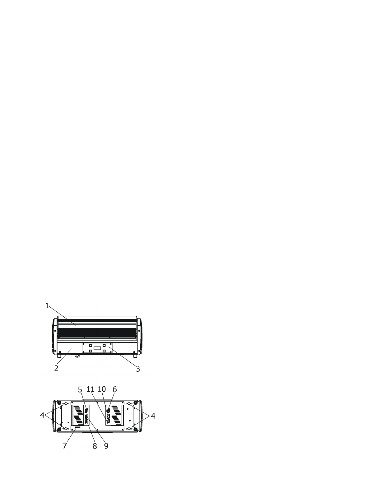
2. Fixture exterior view
1.
Moving head
2. Base of fixture
3. Control panel
4. Apertures for ¼
- turn locks
5. Power IN (Neutrik PowerCon)
6. Power OUT (Neutrik PowerCon)
7. Attachment point for safety wire
8. DMX IN (3-pin XLR)
9. DMX IN (5-pin XLR)
10. DMX OUT (5-pin XLR)
11. DMX OUT (3-pin XLR)
Page 5
Robin CycFX 4
5
3. Installation
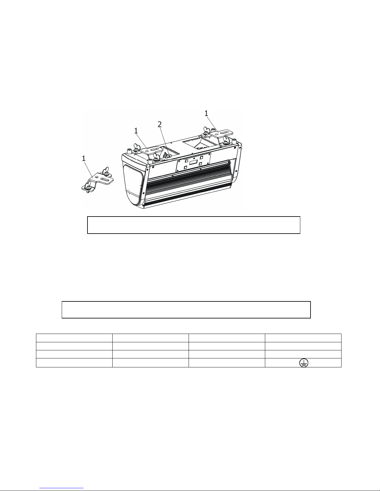
3.1 Rigging the fixture
The Robin CycFX 4 can be rigged in any orientation on a truss without altering its operation characteristics.
Installation on a truss allows the mounting adapters Omega T (1) fastened to the fixture base with ¼-turn quick
locks. Also standard Omega holders for Robe fixtures or mounting bar CF4 (optional accessory) can be used
instead mounting adapters. Pull the safety wire through the attachment point (2) and around the truss.
For overhead use, always install a safety wire that can hold at least 10 times the weight of the fixture. You must
only use safety wire with screw-on carbine.
Ensure that the structure (truss) to which you are attaching
the fixture is secure
Caution: Fixtures may cause severe injuries when crashing down! If you have doubts concerning the safety of a
possible installation, do not install the device and consult installation with an expert.
3.2 Connection to the mains
Fixtures must be installed by a qualified electrician in accordance with all national
and local electrical and construction codes and regulations.
Install a suitable plug on the power cord, note that the cores in the power cord are colored according to the
following table.
C
ore (Eu) C
ore (US) Connection
Plug Terminal Marking
Brown
Black
Live L
Light blue
White
Neutral
N
Yellow/Green Green Earth
This device falls under class one and must be grounded!
Design of the Robin CycFX 4 allows to connect several fixtures to AC mains power in one interconnected daisy
chain using power input and throughput connectors. Needed daisy chain cords are stated in the chapter
“Technical specifications “
The max. number of connected fixtures depends on the AC mains power voltage:
30 fixtures at power supply= 230V
14 fixtures at power supply= 120V
12 fixtures at power supply=100V
Do not overload the supply line and the connecting leads.
Page 6
Robin CycFX 4
6
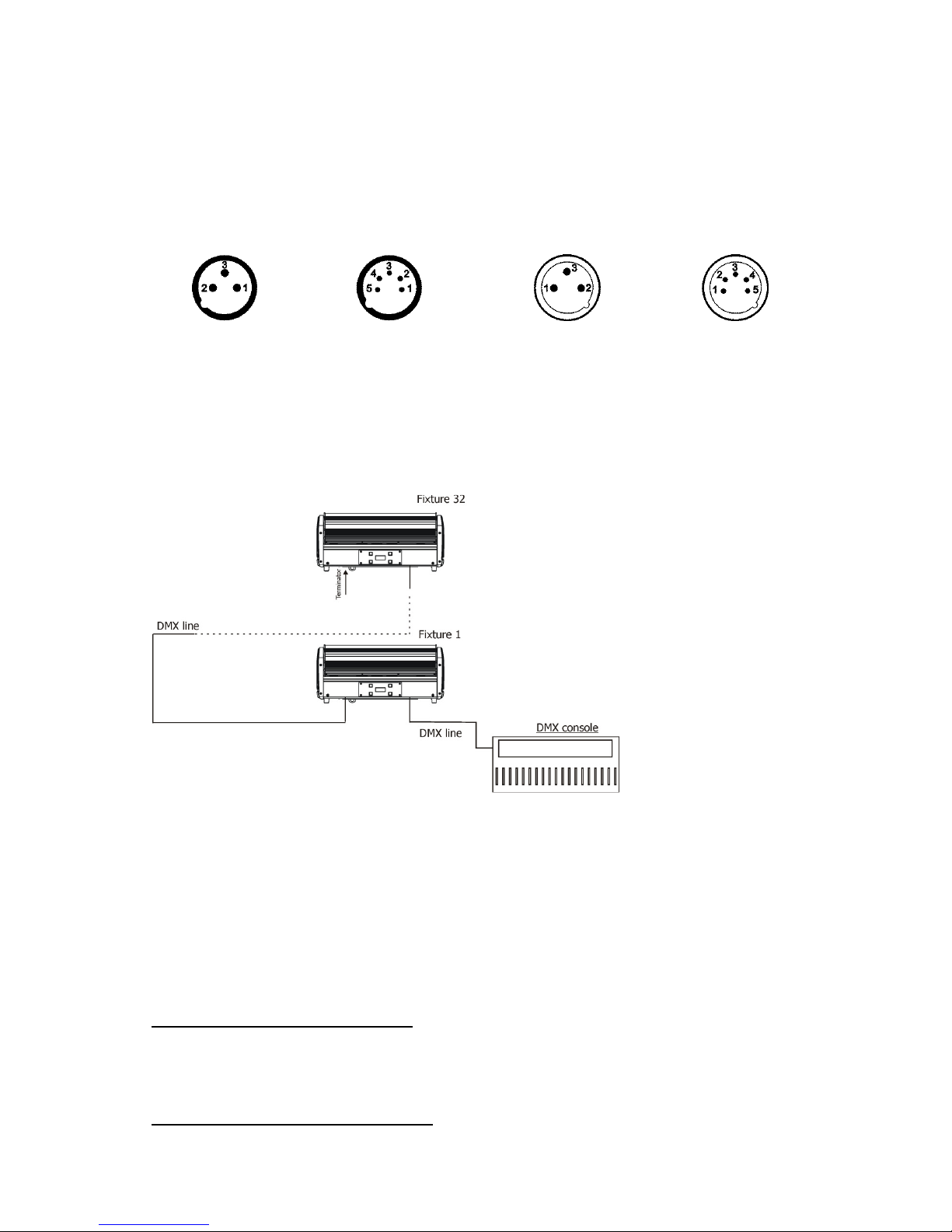
3.3 DMX 512 connection
The fixture is equipped with 3-pin and 5-pin XLR connectors for DMX input/output. Only use a shielded twistedpair cable designed for RS-485 and 3-pin/5-pin XLR- connectors in order to connect the controller with the fixture
or one fixture with another.
Wiring of the XLR connectors:
DMX input DMX output
XLR socket (rear view): XLR plug (rear view):
1
– Shield
2
- Signal (-)
3
- Signal (+)
4
– Not connected
5
– Not connected
To build a DMX chain
1. Connect the DMX output of the controller directly with the DMX input of the first fixture in the DMX chain.
2. Connect the DMX output of the first fixture in the DMX chain with the DMX input of the next fixture.
3. Always connect the DMX output with the input of the next fixture until all fixtures are connected.
Do not overload the link. Max. 32 fixtures may be connected on a DMX link.
Caution: Terminate the link by installing a termination plug in the output of the last fixture. The termination plug is
a male 3-pin XLR plug with a 120 Ohm resistor soldered between Signal (–) and Signal (+).
3.4 Wireless DMX operation
The wireless version of the Robin CycFX 4 (Robin CycFX 4/W) is equipped with the Lumen Radio CRMX module and
antenna for receiving DMX signal. CRMX module operates on the 2.4 GHz band.
1. Select wireless DMX input from the menu PErS (PErS-->dM.IM.-->dM.UL.).
2. To link the fixture with DMX transmitter.
The fixture can be only linked with the transmitter by running the link procedure at DMX transmitter .
After linking , the level of DMX signal ( 0-100 %) is displayed in the menu
item “r.InF“ (SPEC-->rAdI.--> r.InF.)
3. To unlink the fixture from DMX transmitter
.
The fixture can be unlinked from receiver via the menu item “ r.UnL.“ (SPEC-->rAdI.--> r.UnL.).
Page 7
Robin CycFX 4
7
Robin CycFX 4 - DMX protocol
Version 1.0
Mode/Channel
Value Function Type of
control
1 2
3
4
1 1 1 1
0-255
Tilt (8 bit)
Tilt movement by 270°
proportional
- 2 2 2
0-255
Tilt (16 bit)
Fine movement of tilt
proportional
2 3 3 3
0
1
2-255
2-255
Tilt speed (time)
Standard mode
Max. Speed mode
Tilt speed
Speed from max. to min.
Tilt time
Time from 0.2 s to 25.5 s.
Step
step
proportional
proportional
3 4 4 4
0-9
10-14
15-19
20-29
30-39
40-49
50-59
60-69
70-79
80-89
90-99
100-109
110-119
120-129
130-139
140-149
150-179
180-189
190-199
200-209
210-255
Special functions
Reserved
To activate following functions , stop in DMX value
for at least 3 sec. and shutter must be closed at least 3 sec.
(Shutter channel 13/19 must be at range of 0-31 DMX).
Corresponding menu items are temporily overrided except
DMX Input.
DMX input: Wired DMX *
DMX input: Wireless DMX*
* function is active only10 seconds after switching the fixture on
Reserved
RGBW colour mixing mode
CMY colour mixing mode
Tilt speed mode
Tilt time mode
Blackout while tilt moving
Disabled blackout while tilt moving
Silent zoom On
Silent zoom Off
White counting On
White counting Off
Reserved
To activate following reset function, stop in DMX value for at
least 3 sec.
Tilt reset
Reserved
Zoom reset
Reserved
Total reset
Reserved
step
step
step
step
step
step
step
step
step
step
step
step
step
step
step
4 5 5 5
0-255
Red (Cyan)
coarse
- all
pixels
Red LEDs saturation control (0-100%)
proportional
- 6 6 6
0-255
Red (Cyan)
fine -
all
pixels
Red LEDs saturation fine control min.—>max.
proportional
Page 8
Robin CycFX 4
8
5 7 7 7
0-255
Green
(Magenta)
coarse
- all pixels
Green LEDs saturation control (0-100%)
proportional
- 8 8 8
0-255
Green (Magenta)
fine -
all
pixels
Green LEDs saturation fine control min.—>max.
proportional
6 9 9 9
0-255
Blue (Yellow)
coarse
- all
pixels
Blue LEDs saturation control (0-100%)
proportional
- 10
10
10
0-255
Blue (Yellow) fine
- all
pixels
Blue LEDs saturation fine control min.—>max.
proportional
7 11 11 11
0-255
White
coarse (RGBW mode only)
-
all
pixels
White LEDs saturation control (0-100%)
proportional
- 12 12 12
0-255
White fine (RGBW mode
only)
- all
pixels
White LEDs saturation fine control min.—>max.
proportional
8 13 13 13
0
1-255
CT0
(
All pixels
)
No function
Colour temperature correction
step
proportional
9 14 14 14
0
1-2
3
4-5
6
7-9
10-12
13-15
16
17-55
56
57 - 95
96
97 – 134
135
136 - 174
175
176 -214
215
216 - 246
247
248-251
252-255
Virtual c
olour
wheel (All pixels)
No function
White 2700 K
White 2700 K (tungsten emulation)**
White 3200 K
White 3200 K (tungsten emulation)**
White 4200 K
White 5600 K
White 8000 K
Blue (Blue=full, Red+Green+White=0)
Red=0, Greenup,Blue =full, White=0
Light Blue
(Red=0, Green=full, Blue =full, white=0)
Red=0, Green=full, Bluedown, White=0
Green (Red=0, Green=full, Blue =0, White=0)
Redup, Green=full, Blue=0, White=0
Yellow
(Red=full, Green=full, Blue=0,White=0)
Red=full, Greendown, Blue=0, White=0
Red(Red=full, Green=0, Blue=0, White=0)
Red=full, Green=0, Blueup, White=0
Magenta
(Red=full, Green=0, Blue=full, White=0)
Reddown, Green=0, Blue=full, White=0
Blue (Red=0, Green=0, Blue=full, White=0)
Rainbow effect
( with fade time)
from min.->max. s
peed
Rainbow
effect(without fade time)from min
.->
max.speed
step
step
step
step
step
step
step
step
step
proportional
step
proportional
step
proportional
step
proportional
step
proportional
step
proportional
step
proportional
proportional
10 15 15 15
0-2
3-4
5-6
:
181-182
183-255
Pixel effects
(see table below)
No function
Effect 1
Effect 2
:
Effect 90
Reserved
step
step
:
step
Page 9
Robin CycFX 4
9
11 16 16 16
0-63
64-127
128-191
192-255
Pixel effects speed
Speed from min. —>max. without fade time
Speed from max. —>min. without fade time (op. direction)
Speed from min. —>max. with fade time
Speed from max. —>min. with fade time
(op. direction)
proportional
proportional
proportional
proportional
12 17 17 17
0-255
Zoom
coarse
Zoom from min. to max. beam angle
proportional
- 18 18 18
0-255
Zoom fine
Fine zooming from min.—>max.
proportional
13 19 19 19
0-31
32-63
64-95
96-127
128-143
144-159
160-191
192-223
224-255
Shutter/ Strobe
(All pixels)
Shutter closed
Shutter open
Strobe-effect from slow to fast
Shutter open
Opening pulses in sequences slow--> fast
Closing pulses in sequences fast --> slow
Shutter open
Random strobe-effects from slow to fast
Shutter open
step
step
proportional
step
proportional
proportional
step
proportional
step
14 20 20 20
0 - 255
Dimmer
coarse (All pixels)
Dimmer intensity from 0% to 100%
proportional
- 21 21 21
0 - 255
Dimmer
fine (All pixels)
Dimmer intensity from min.—>max.
proportional
- - 22 22
0-255
Red pixel 1
Red LED saturation control (0-100%)
proportional
- - 23 23
0-255
Green
pixel
1
Green LED saturation control (0-100%)
proportional
- - 24 24
0-255
Blue
pixel 1
Blue LED saturation control (0-100%)
proportional
- - - 25
0-255
Dimmer 1
Dimmer intensity from 0% to 100%
proportional
- - 25 26
0-255
Red pixel 2
Red LED saturation control (0-100%)
proportional
- -
26
27
0-255
Green
pixel 2
Green LED saturation control (0-100%)
proportional
- -
27
28
0-255
Blue
pixel 2
Blue LED saturation control (0-100%)
proportional
- - - 29
0-255
Dimmer 2
Dimmer intensity from 0% to 100%
proportional
- - 28 30
0-255
Red pixel 3
Red LED saturation control (0-100%)
proportional
- - 29 31
0-255
Green
pixel 3
Green LED saturation control (0-100%)
proportional
Page 10

Robin CycFX 4
10
- - 30 32
0-255
Blue
pixel 3
Blue LED saturation control (0-100%)
proportional
- - - 33
0-255
Dimmer 3
Dimmer intensity from 0% to 100%
proportional
- - 31 34
0-255
Red pixel 4
Red LED saturation control (0-100%)
proportional
- - 32 35
0-255
Green
pixel 4
Green LED saturation control (0-100%)
proportional
- - 33 36
0-255
Blue
pixel 4
Blue LED saturation control (0-100%)
proportional
- - - 37
0-255
Dimmer 4
Dimmer intensity from 0% to 100%
proportional
**Halogen lamp effect during dimming
Tilt movement direction and pixel order:
Channel Pixel effects
DMX value
Effect
Type of
Control
0-2 No function
Step
3-4 Effect 1
Step
5-6 Effect
2 Step
7-8 Effect
3
Step
9-10 Effect
4
Step
11-12 Effect
5
Step
13-14 Effect
6
Step
15-16 Effect
7
Step
17-18 Effect
8
Step
19-20 Effect
9
Step
21-22 Effect
10
Step
23-24 Effect
11
Step
25-26 Effect
12
Step
27-28 Effect
13
Step
29-30 Effect
14
Step
31-32 Effect
15
Step
33-34 Effect
16
Step
35-36 Effect
17
Step
37-38 Effect
18
Step
39-40 Effect
19 Step
Page 11

Robin CycFX 4
11
41-42 Effect
20
Step
43-44 Effect
21
Step
45-46 Effect
22
Step
47-48 Effect
23
Step
49-50 Effect
24
Step
51-52 Effect
25
Step
53-54 Effect
26
Step
55-56 Effect
27
Step
57-58 Effect
28
Step
59-60 Effect
29
Step
61-62 Effect
30
Step
63-64 Effect
31
Step
65-66 Effect
32
Step
67-68 Effect
33
Step
69-70 Effect
34
Step
71-72 Effect
35
Step
73-74 Effect
36
Step
75-76 Effect
37
Step
77-78 Effect
38
Step
79-80 Effect
39
Step
81-82 Effect
40
Step
83-84 Effect
41
Step
85-86 Effect
42
Step
87-88 Effect
43
Step
89-90 Effect
44
Step
91-92 Effect
45
Step
93-94 Effect
46
Step
95-96 Effect
47
Step
97-98 Effect
48
Step
99-100 Effect
49
Step
101-102 Effect
50
Step
103-104 Effect
51
Step
105-106 Effect
52
Step
107-108 Effect
53
Step
109-110 Effect
54
Step
111-112 Effect
55
Step
113-114 Effect
56
Step
115-116 Effect
57
Step
117-118 Effect
58
Step
119-120 Effect
59
Step
121-122 Effect
60
Step
123-124 Effect
61
Step
125-126 Effect
62
Step
127-128 Effect
63
Step
129-130 Effect
64
Step
131-132 Effect
65
Step
133-134 Effect
66
Step
135-136 Effect
67
Step
137-138 Effect
68
Step
139-140 Effect
69
Step
141-142 Effect
70
Step
143-144 Effect
71
Step
Page 12

Robin CycFX 4
12
145-146 Effect
72
Step
147-148 Effect
73
Step
149-150 Effect
74
Step
151-152 Effect
75
Step
153-154 Effect
76
Step
155-156 Effect
77
Step
157-158 Effect
78
Step
159-160 Effect
79
Step
161-162 Effect
80
Step
163-164 Effect
81
Step
165-166 Effect
82
Step
167-168 Effect
83
Step
169-170 Effect
84
Step
171-172 Effect
85
Step
173-174 Effect
86
Step
175-176 Effect
87
Step
177-178 Effect
88
Step
179-180 Effect
89
Step
181-182 Effect
90 Step
183-
255 Reserved
Page 13

Robin CycFX 4
13
5. Control menu map
Default settings=Bold print
Level 1
Level 2
Level 3
Level 4
Level 5
Level 6
Level 7
DMXA
Set DMXA
001-255
Info
POn Time
Total
Reset
DMX In
Tilt 0-255
:
Dimm
F 0-255
Temp
Current
High Res
Highest
Sw Ver
IC-1
IC-2
IC-3
IC-4
Pers
DMX Pres
Mode 1
:
Mode
4
DMX In
Wired
Wireless
Tilt Rev
On,
Off
T. Mode
Speed
Time
T. Feed
On, Off
BLC DMC
On,
Off
Act BLC
T Mov
On,
Off
Display
Turn
Page 14

Robin CycFX 4
14
Level 1
Level 2
Level 3
Level 4
Level 5
Level 6
Level 7
On/Off T
On, Off
Contrast
0-
100%
Backlight
0-
100%
C Cal M
On, Off
C Mix M
RGBW
, CMY
Whi Cnt
On, Off
Sil Zom
On,
Off
Mic Sens
0...10...19
I Ef Pos
Tilt
:
Dimm
F
Store
Defaults
Manual
Tilt
:
Dimm F
Test Prg
Sta Alone
Music T
On,
Off
Auto Run
Off
Test
User
Pr Play
Test Prg
User Prg
Pr Edit
Step 1
Prg End
: Tilt
Step 42
:
Copy
Page 15

Robin CycFX 4
15
Level 1
Level 2
Level 3
Level 4
Level 5
Level 6
Level 7
Reset
Special
RDM Low
RDM Hight
Wireless
Stat
Unlink
Adjust
DMX Val
Tilt 0-255
:
Dimm
F 0-
255
Calib
Cal Mech
Tilt C.
0-
255
Store
Cal Col
R C 1
0-
255
G C 1
0-
255
B C 1
0-
255
W C 1
0-
255
:
R C 4 0-
255
G C 4 0-
255
B C 4 0-
255
W C 4 0-
255
Store
Cal Temp
Load d
C
Sw Upd
On, Off
Page 16

Robin CycFX 4
16
6. Control menu
The Robin CycFX 4 is equipped with 2-line LCD display which allows to set the fixture´s behaviour according to
your needs, obtain information on its operation, control various range of effects and lastly program it, if it has to be
used in a stand-alone mode.
Control board:
[ESCAPE] button used to leave the menu without saving changes.
[NEXT] , [PREV] buttons for moving between menu items and for value adjusting.
[ENTER] button used to enter the selected menu (menu item) and to confirm adjusted value.
After switching the fixture on, display shows current DMX address
.
Note: to turn the display , press and hold the [ESCAPE].
6.1 Addressing (DMXA)
Set DMXA- Use this menu item to set the DMX start address of the fixture, which is defined as the first channel
from which the Robin will respond to the controller.
If you set, for example, the address 15, the Robin CycFX 4 will use channels 15 - 28 for control (if Mode 1 is
selected).
Please, be sure that you do not have any overlapping channels in order to control each Robin CycFX 4 correctly and
independently from any other fixture on the DMX data link.
If there is no data received at the DMX input, the display will start to flash "0001” with actually stored DMX
address.
6.2 Fixture information (Info)
POn Time - Power on time. Select this menu to read the number of fixture operation hours.
Total - The item shows the total number of the operation hours since
the Robin CycFX 4 has been fabricated.
Reset - The item shows the number of the operation hours that the
Robin CycFX 4 has been powered on since the counter was last reset.
In order to reset this counter to 0, press and hold both [NEXT] and [PREV] buttons and the
[Enter] button at the same time.
DMX In - DMX readout. The menu is used to read DMX values of each channel received by the fixture.
Temp - Temperature. The menu shows temperature in the moving LED head.
Current - A current temperature of the moving LED head.
Highest - A maximum temperature of the moving LED head since the fixture has
been fabricated.
High Res
- A maximum temperature of the the moving LED head since the counter
was last reset.
In order to reset this counter, press and hold both [NEXT] and [PREV] buttons and the
[Enter] button at the same time.
Page 17

Robin CycFX 4
17
Sw Ver - Software versions. Select this item to read the software version of the fixture modules.
IC-1 - A zoom processor.
IC-2 - A display processor.
IC-3 - LED driver processor.
IC-4 - LED control processor
6.3 Personality (Pers)
DMX Pres - DMX preset. Use the menu to select desired channel mode.
Mode 1 - 14 control channels
Mode 2 - 21 control channels
Mode 3 - 33 control channels
Mode 4 - 37 control channels
DMX In - DMX input.
Use the menu to select mode of receiving DMX signal.
Wired -
DMX signal is received by means of the standard DMX cable.
Wireless - DMX signal is received by means of the inbuilt wireless module.
Tilt Rev - Tilt reverse. The item allows to invert tilt movement of the LED head.
T Feed - Tilt Feedback. The menu item allows to return the mowing head to the required tilt position after
changing the position by an external force if this option is set on.
Note. The Tilt Feedback should be permanent On, the option Off is not suitable for standard operation and the
head of the fixture can be damaged!
BLC DMC - Blackout during movement correction. Set this option on if you wish to close light
output during the time when the head goes to its correct position, which has been changed by an
external force.
Act Blc - Active blackout. Use this menu if you wish to close the light output during effect changes.
P/T Mov - The menu item allows to close light output while the tilt coordinates
are changing.
Display - Display adjusting. This menu allows you to adjust the display behaviour.
Turn - This function turns the display by 180°.
On/Off T - This function allows you to keep the display permanent on or turn it off two
minutes after last pressing any button on the control panel.
Contrast- Use this function to adjust contrast of the display (0-100%).
Backlight- Use this function to adjust backlight of the display (0-100%).
C Cal M - Colour calibration mode. If the functin is on, the white output (2700K-8000K) from the fixture (and also
mixed colours) is more uniform. Each colour is dynamically corrected according to the value set in the menu
"Calibrate Effects" (Special-> Adjust-> Calib).
C Mix M - Colour mixing mode. This item allows switching into RGBW or CMY mode. In the CMY mode, the
white(8bit)/white (16) bit channels are not active.
Whi Cnt – White counting. If this function is On, the white LED of each pixel lights when a white colour is mixed.
The light intensity of the white LED is in a proportion to the intensity of the rest of pixel´s LEDs (red, Green, blue)
and improves the white output of the pixel. The function influences “pixel modes” only - DMX mode 3 and 4 (and
RGBW colour mixing mode has to be set).
Sil Zom
– Silent zoom. If this function is on, a speed of the zoom movement is redused and at the same time
a noise of this movement.
Page 18

Robin CycFX 4
18
Mic Sens - Microfon sensitivity. Enter the menu if you want to adjust the microphone sensitivity ( 1-max., 19-min.).
Temp Uni - Temperature unit. Use the menu item to change temperature unit from °C to °F.
I Ef Pos - Init effect positions. Use the menu to set all effects to the desired positions at which they will stay after
switching the fixture on without DMX signal connected.
Defaults - The menu item allows to set all fixture parameters to the default (factory) values.
6.4 Manual Control (Manual)
Manual C - Manual control. Use the menu to control all fixture channels by means of the control panel. Displayed
menu items depend on selected DMX mode.
6.5 Test program (Test Prg)
Use this menu item to run a special demo-test sequences without an external controller, which will show you some
possibilities of using Robin CycFX.
6.6 Stand-alone (St Alone)
Auto Run - Presetting playback. This function allows you to select the program which will be played in the standalone mode after switching the fixture on. Selected program will be played continuously in a loop.
Off - The option disables „Auto Run” function.
Test - The option will start built-in test program.
User - The option will start user-created program
Pr Play - Playing program. Select this menu to run a user-created program in a loop.
Test Prg - The option runs built-in test program.
User Prg - The option runs user-created program
Select the program you wish and press [ENTER]. The selected program starts running. By Pressing [ENTER] again,
program pauses running.
Pr Edit - Editing program. Select this menu to edit or create the program. The Robin CycFX 4 has one built-in
program and one user-editable program up to 42 steps. Each program step has a step time during which effects
last in the current step.
To edit program:
Procedure:
1. Press [NEXT] or [PREV] to select the menu "Pr Edit" and press [ENTER].
2. Press [NEXT] or [PREV] to select the desired program step and press [ENTER] button.
3. Press [NEXT] or [PREV] to select the desired item and press [ENTER] button. Now you can edit by [NEXT] or
[PREV] buttons the DMX value (0-255) for selected item:
Prg End. a total number of the program steps (value 1-42). This value you should be set before
starting of programming (e.g. if you want to create program with the 10 steps, set Prg End=10).
Tilt a tilt movement Stro a strobe/shutter
Tilt S a tilt speed Dimm a dimmer
Power a power/special functions R L 1 a red LED pixel 1
R L A red LEDs (all pixels) G L 1 a green LED pixel 1
G L A green LEDs (all pixels) B L 1 a blue LED pixel 1
B L A blue LEDs (all pixels) Dim 1 a dimmer for pixel 1
Page 19

Robin CycFX 4
19
W L A white LEDs (all pixels) R L 8 a red LED pixel 4
CTO a colour temperature correction G L 8 a green LED pixel 4
Vir C a virtual colour B L 8 a blue LED pixel 4
Pix E pixel effects Dim 1 a dimmer for pixel 1
Px E S a pixel effect speed S.Tm a step time (0-25.5 sec)
Zoom a zoom movement COPY copying the current prog. step to
the next prog. step
4. Press [ENTER] button to confirm adjusted value .
5. Press [ESCAPE] button, select next prog. step, press [ENTER] button and repeat steps 3 - 5).
6.7 Reset
This option enables the Robin CycFX 4 to index all effects and return to their standard positions.
6.8 Special functions (Special)
RDM Low - This menu item shows the first part of the RDM identification code.
RDM High - This menu item shows the second part of the RDM identification code.
Wireless - Wireless DMX status. The menu serves for reading of the wireless operation status.
Stat - Wireless DMX information. The menu item shows level of received signal in %.
UnLink - Wireless DMX unlink. The item serves for unlinking the fixture from transmitter.
Adjust - Adjustment. The menu allows the fine adjustment of colours.
DMX Val- DMX values. Use the menu to set DMX values of fixture´s channels.
Calib - A calibration of tilt position of head and white colours.
Cal Mech - A calibration of tilt position.
Note: you can also use DMX controler for calibration of tilt position of head, calibration protocol is following:
Effect Mode 1 Mode 2 Mode 3 Mode 4
Tilt- fine tilt movement channel 15 channel 22 channel 34 channel 37
Cal Col - A calibration of colours.
Cal Temp - A setting of temperature of the control processor for LEDs calibration. This
temperature has to be set before calibration of colours. Disconnect the fixture from mains and let it at room
temperature (cca 25°C) until the fixture gets ambient temperature (as it can last 2 hours and more, better is used
cold fixture before its operation). After that, set the ambient (room) temperature in this menu.
Sw Upd - Software update. The menu item allows you to update software in the fixture via either serial or USB
port of PC.
The following are required in order to update software:
- PC running Windows 95/98/2000/XP/7 or Linux
- DMX Software Uploader
- Flash cable RS232/DMX No.13050624 (if you want to use a serial port of PC)
- Robe Universal Interface (if you want to use an USB port of PC)
Note 1: Software update should execute a qualified person. If you lack qualification, do not attempt the update
yourself and ask for help your ROBE distributor.
Note 2: DMX address, programs 1-3 and all items in the menu "Pers" will be set to their default (factory) values.
To update software in the fixture:
I. Installation of the DMX Software Uploader.
1. DMX Software Uploader program is available from the ROBE web site at WWW.robe.cz.
2. Make a new directory ( e.g. Robe_Uploader) on your hard disk and download the software to it.
3. Unpack the program to the directory.
Page 20

Robin CycFX 4
20
II.Fixture software updating.
1.Determine which of your ports is available on your PC and connect it:
- with the DMX input of the fixture if you using the flash cable RS232/DMX
- with the DMX output of the Robe Universal Interface if you using the USB cable.
Disconnect the fixture from the other fixtures in a DMX chain. Turn both the computer and
the fixture on. Make sure the lamp is switched off (only if the fixture involves a lamp).
2. Switch the fixture to the updating mode by selecting the "SW Upd " item and press [ENTER].
Note: If you do not want to continue in software update, you have to switch off and on the fixture
to escape from this menu.
We recommend to cancel all running programs before starting the Software Uploader.
3. Run the Software Uploader program. Select desired COM and then click on the Connect button.
(Select COM if the serial port is used or Robe Universal Interface if the USB port is used).
If the connection is OK, click on the “Start Uploading button“ to start uploading. It will take several
minutes to perform software update.
If the option "Incremental Update" is not checked, all processors will be updated (including
processors with the same software version).
If you wish to update only later versions of processors, check the “Incremental Update box“.
Avoid interrupting the process. Update status is being displayed in the Info Box window.
When the update is finished, the line with the text “The fixture is successfully updated“ will appear in
this window and the fixture will reset with the new software.
Note: In the case of an interruption of the upload process (e.g. power cut), the fixture keeps the updating mode
and you have to repeat the software update again.
7. RDM
This fixture is ready for RDM operation. RDM (Remote Device Management) is a bi-directional communications
protocol for use in DMX512 control systems, it is the new open standard for DMX512 device configuration and
status monitoring.
The RDM protocol allows data packets to be inserted into a DMX512 data stream without adversely affecting
existing non-RDM equipment. By using a special „Start Code,“ and by complying with the timing specifications for
DMX512, the RDM protocol allows a console or dedicated RDM controller to send commands to and receive
messages from specific moving lights.
RDM allows explicit commands to be sent to a device and responses to be received from it.
The list of commands for Robin 8 is the following.
Parameter ID Discovery command SET command GET command
DISC_UNIQUE_BRANCH *
DISC_MUTE *
DISC_UN_MUTE *
DEVICE_INFO
*
SUPPORTED_PARAMETERS
*
SOFTWARE_VERSION_LABEL
*
DMX_START_ADDRESS
* *
IDENTIFY_DEVICE
* *
DEVICE_MODEL_DESCRIPTION
*
Page 21

Robin CycFX 4
21
MANUFACTURER_LABEL
*
DEVICE_LABEL
* *
SENSOR_DEFINITION
*
SENSOR_VALUE
*
DISPLAY_LEVEL
* *
DEVICE_RESET
*
DMX_PERSONALITY
* *
DMX_PERSONALITY_DESCRIPTION
*
STATUS_MESSAGES
*
STATUS_ID_DESCRIPTION
*
DEVICE_HOURS
*
Please, see the Robe Universal Interface user manual for detail description of RDM operation.
8. Technical specifications
Power supply
• Electronic auto-ranging
• Input voltage: 100 - 240V AC, 50-60 Hz
• Fuse: T2.5 A
• Max. power consumption*: 80W@230V (power factor=0,84; I=0,4A)
*Allow for a deviation of +/-10%
• Mains input: CE - max. 16A
cETLus - max. 10 A
• Mains output: CE - max. 15A
cETLus - max. 9 A
Optic & Effects
• Light source: Array of 4 x 15W RGBW LED multichips
• Zoom range: x-axis: 8.5°-41°( at ½ beamu)
16°-63° (at 1/10 beamu )
y-axis: 8°-40°( at ½ beamu)
15°-62°(at 1/10 beamu )
• RGBW or CMY colour mixing
• Built-in colour macros and pixel effects
• Adjustable strobe sequences
•Typical Lumen maintenance: 70% @ 60.000 hours
Control
• Setting & Addressing: two-row LCD display & 4 control buttons
• Control: USITT DMX 512 (RDM support)
• DMX protocol modes: 4 (14,21,33,37 controll channels)
• Operations modes: DMX, Stand-alone
• Manual control of all effects via control panel
• One editable program, up to 42 steps
Page 22

Robin CycFX 4
22
Wireless DMX/RDM module (only for Robin CycFX 4 Wireless DMX)
• Compliance with USITT DMX-512 (1986 & 1990) and 512-A
• Full DMX fidelity and frame integrity
• Auto sensing of DMX frame rate and frame size
• <5ms DMX latency
• Operational frequency range of 2402-2480 MHz
• Producer: LumenRadio
Strobe
• Strobe effect with variable speed (max. 20 flashes per second)
• Pre-programmed random strobe pulse-effects
Dimmer
• Smooth 16-bit dimming from 0 - 100 %
Connection
•DMX data in/out: Locking 3-pin & 5-pin XLR
•Power In: Chassis connector Neutrik PowerCon, A-type, NAC3MPA
•Power Out: Chassis connector Neutrik PowerCon, B-type, NAC3MPB
Rigging
• Via 2 mounting adapters
Temperatures
• Maximum ambient temperature: 40° C
• Maximum housing temperature: 70° C
Minimum distances
Min. distance from flammable surfaces: 0.2 m
Min. distance to lighted object: 0.3 m
Total heat dissipation
• 648 BTU/h (calculated)
Weight
• 6.8 kg
Page 23

Robin CycFX 4
23
Dimensions (mm)
Mounting bar CF4 (optional)
Included items
• 1 x Robin CycFX
• 2 x Mounting adapter Omega T (P/N 99014009)
• 1 x User manual
Page 24

Robin CycFX 4
24
Optional accessories
(P/N 99010420) Omega holder
(P/N1305 1731) Mains Cable PowerCon In/open ended, 2m
(P/N 1305 1724) Mains Cable PowerCon In/Schuko, 2m
(P/N 1305 1725) Mains Cable PowerCon In/CEE 16A, 2m
(P/N 1305 1726) Mains Cable PowerCon In/US, 2m
(P/N 1305 1727) Daisy Chain PowerCon In/Out, EU, 2m
(P/N 1305 1728 ) Daisy Chain PowerCon In/Out, US, 2m
(P/N 1098 0210) Mounting Bar CF4
Page 25

Robin CycFX 4
25
Beam distribution
Page 26

Robin CycFX 4
26
Page 27

Robin CycFX 4
27
9. Cleaning and maintenance
DANGER !
Disconnect from the mains before starting any cleaning or maintenance work
The front transparent cover will require monthly cleaning as smoke fluid tends to build up residues, reducing the
light output very quickly. For cleaning use a wet clout or an air-jet. Do not use solvents or any other aggressive
cleaning fluid.
Maintenance and service operations are only to be carried out by a qualified person.
Should you need any spare parts, please use genuine parts.
9.1 Replacing a fuse
This replacement has to be realized by a qualified person or ROBE service worker only.
Specifications are subject to change without notice.
June 16, 2014
Page 28

Robin CycFX 4
28
 Loading...