

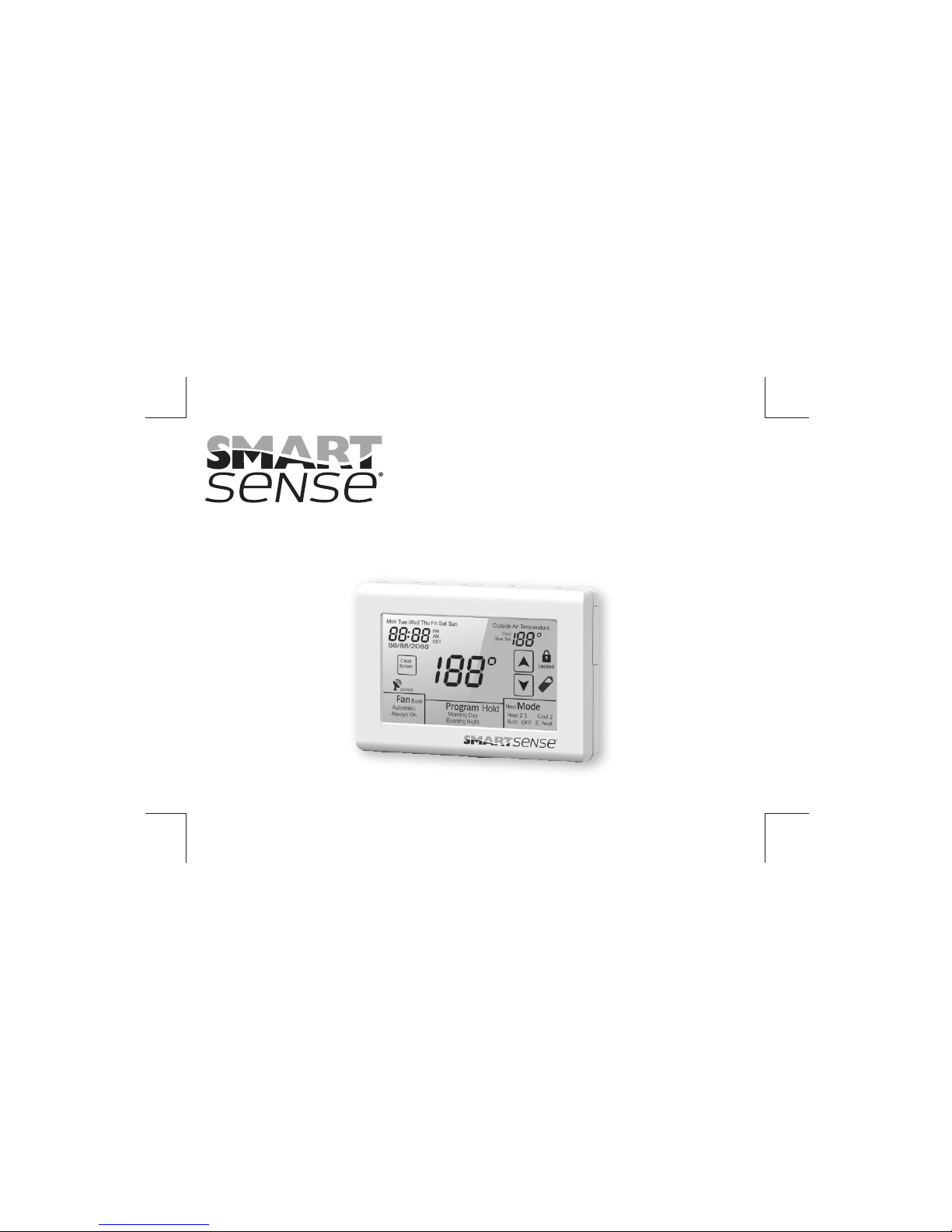
Robertshaw Smart Sense SMART 1000 Installation Manual
www.robertshaw.com
©2015 Robertshaw 12/15 – 352-00242-001
SMART 1000
Touchscreen Thermostat
Installation Manual
by Uni-Line®

IMPORTANT SAFETY INFORMATION
WARNING: ELECTRICAL SHOCK HAZARD – Turn off power at the main
power source by unscrewing fuse or switching circuit breaker
to the OFF position before installing, removing, or cleaning
this thermostat.
WARNING: FIRE AND ELECTRIC SHOCK HAZARD – This device should be
installed by a qualified service technician with due regard
for safety as improper installation could result in a fire and
electric shock hazard.
WARNING: FIRE AND ELECTRICAL SHOCK HAZARD – This is a 24V AC
low-voltage thermostat. Do not install on voltages higher than
30V AC.
• Donotswitchsystemtocoolifthetemperatureisbelow50°F(10°C).Thiscan
damageyourcoolingsystemandmaycausepersonalinjury.
• Donotshort(jumper)acrossterminalsonthegasvalveoratthesystemcontrol
totestinstallation.Thiswilldamagethethermostatandvoidthewarranty.
• Donotconnectgroundtoanyterminalinthisunit.
• Allwiringmustconformtolocalandnationalbuildingandelectricalcodesand
ordinances.
• Usethisthermostatonlyasdescribedinthemanual.


TABLE OF CONTENTS
1
Introduction ............................................................................................................................................4
Getting Started .......................................................................................................................................5
Installing the Thermostat .....................................................................................................................6, 8
Disassembly ..........................................................................................................................6
Thermostat Location ..............................................................................................................6
Mounting the Subbase ........................................................................................................6, 7
Terminal Designations ............................................................................................................8
Setting the System Switches ..................................................................................................................9
System Switch Functions .....................................................................................................................10
Installing the Batteries ..........................................................................................................................11
Typical System Wiring Diagrams .....................................................................................................12, 20
Heat only (Gas) ....................................................................................................................12
Heat only (Electric)................................................................................................................13
Cool only (Single or Multi-stage) ...........................................................................................14
1 Heat / 1 Cool (Gas) .............................................................................................................15
2 Heat / 2 Cool (Gas) .............................................................................................................16
2 Heat / 1 Cool (Heat Pump) ..................................................................................................17
3 Heat / 2 Cool (Heat Pump) ..................................................................................................18

TABLE OF CONTENTS
2
TABLE OF CONTENTS
2 Heat / 1 Cool (Fossil Fuel) ..................................................................................................19
3 Heat / 2 Cool (Fossil Fuel) ..................................................................................................20
Installer Setup Menu ........................................................................................................................21,38
Entering the Setup Menu ......................................................................................................21
Selecting Programmable or Non-programmable Operation ..................................................22
Selecting Number of Program Events ...................................................................................23
Selecting Mode ....................................................................................................................24
Selecting Programmable Fan ...............................................................................................25
Assigning Auxiliary Contacts ................................................................................................26
Selecting Touchscreen Lock Options ....................................................................................27
Selecting the Cooling Setpoint Limit .....................................................................................28
Selecting the Heating Setpoint Limit .....................................................................................29
Selecting Back Light Option ..................................................................................................30
Selecting Adaptive Recovery Option ....................................................................................31
Selecting First Stage Heating and Cooling Differential Option ...............................................32
Selecting Second Stage Heating and Cooling Differential Option ..........................................33
Selecting Third Stage Heating Differential Option .................................................................34
Selecting Demand Staging or Locked Staging Option ...........................................................35
Sensor Calibration ...............................................................................................................36
Selecting Low Balance Point Option .....................................................................................37
Selecting High Balance Point Option ....................................................................................38
Selecting Temperature Display Format.............................................................................39
Enabling E.HEAT Mode........................................................................................................40

TABLE OF CONTENTS
3
Remote Sensor Installation .............................................................................................................41, 43
Remote Sensor Types ..........................................................................................................41
SMART-R-02 Indoor Sensor Installation .........................................................................41, 42
SMART-R-03 Outdoor Sensor Installation ...........................................................................42
Temperature/Resistance Chart ............................................................................................43
Display Functions .................................................................................................................................44
Testing ............................................................................................................................................45, 49
Fan Operation ......................................................................................................................45
Conventional Heating ...........................................................................................................45
Conventional Cooling .....................................................................................................45, 46
Conventional Heat Pump .....................................................................................................46
Fossil Fuel ............................................................................................................................47
Low Balance Point ..........................................................................................................47, 48
High Balance Point ...............................................................................................................48
Adaptive Recovery .........................................................................................................48, 49
Programmable Fan ..............................................................................................................49
Auxiliary Contacts ................................................................................................................49
Basic Troubleshooting ....................................................................................................................50, 51
Specifications .......................................................................................................................................52

INTRODUCTION
The SMART 1000 is a feature-rich touchscreen thermostat that can be battery powered or hardwired to
the HVAC equipment. Using a common sense approach to the installation will ensure this product is
installed properly and to the customer’s satisfaction. Please take time to read and understand this
manual so that installation and testing is performed in an efficient manner.
This manual is to be used in conjunction with the supplied Owners Manual.
Although great care has been taken in the preparation of this manual, Uni-Line
®
takes no
responsibility for errors or omissions contained herein. It is the responsibility of the installer
to ensure that this thermostat and the equipment connected to it operate in a safe and efficient
manner.
Due to ongoing product improvements, Uni-Line reserves the right to change the
specifications of the SMART 1000 thermostat or its components without notice.
All rights reserved.
© Uni-Line
Intellectual rights apply.
4

GETTING STARTED
As with any HVAC project, careful installation is the key to a successful outcome.
Time taken during the installation process will be rewarded with fewer call-backs.
The steps required to install the SMART 1000 thermostat are as follows.
1. Read and understand this Installation Manual and Owners Manual.
2. Mount and wire the subbase.
3. Install the batteries.
4. Set the 4 system switches to match the equipment application.
5. Wire optional remote temperature sensor(s).
6. Power the thermostat
7. Set the Advanced Installer settings.
8. Test the thermostat.
5
INSTALLING THE THERMOSTAT
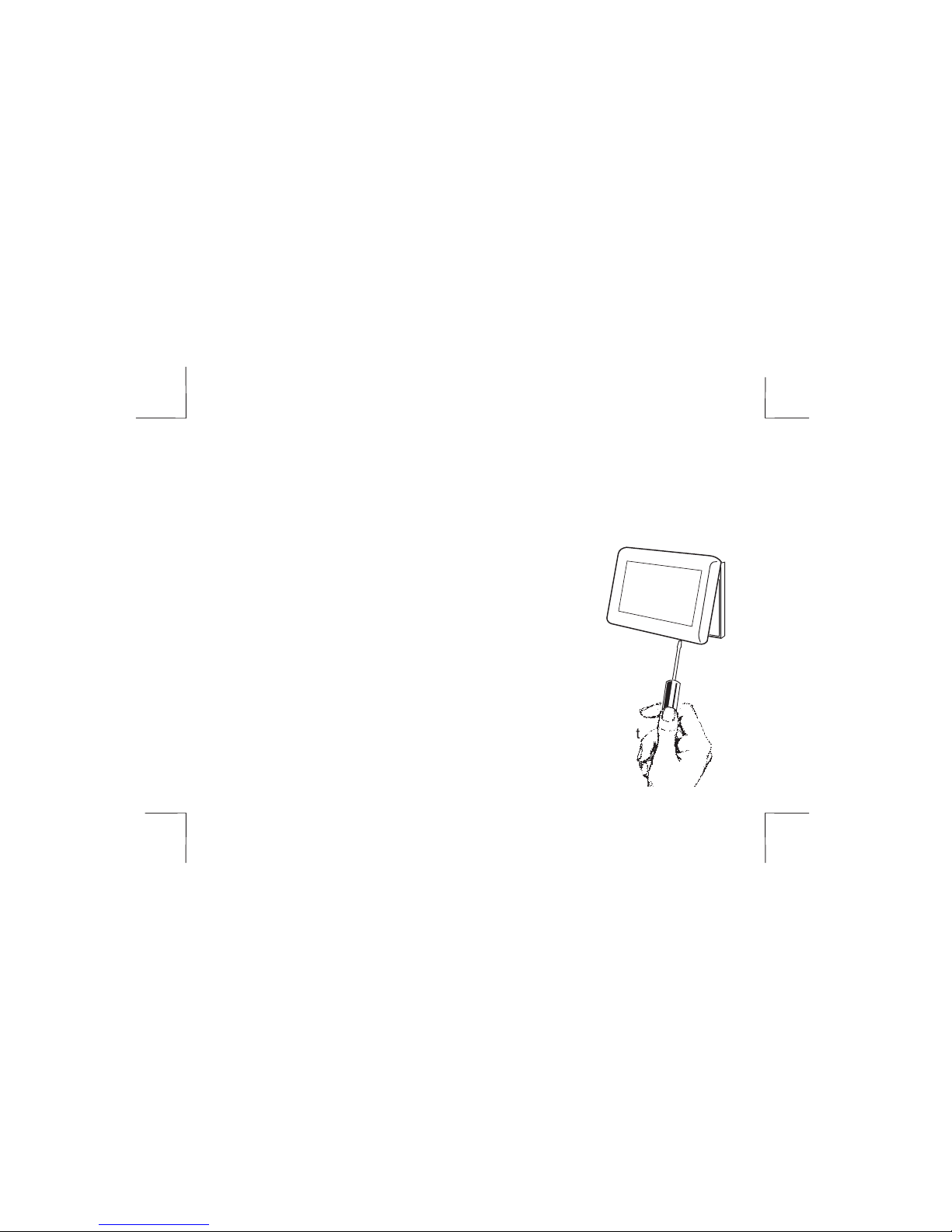
DISASSEMBLY
There are two release slots located on the bottom of the thermostat. Gently push
the flat blade of a small screwdriver into one slot at a time and pry upward until
the catch disengages. Carefully swing the thermostat upward and away from the
subbase. (Figure 1)
THERMOSTAT LOCATION
The SMART 1000 should be installed in a location that
represents the ambient space temperature. Do not install
the thermostat in an area where drafts are present, near
the floor, behind doors or on an external wall. Avoid
placing the thermostat in areas where the air movement
is limited, affected by direct sunlight or other areas not
represented by typical of the temperature in the space.
MOUNTING THE SUBBASE
When mounting the SMART 1000 subbase, be aware that drafts
may travel down wall cavities and enter the back of the thermostat
through the control wire hole in the wall. It is important to seal
the hole to prevent any drafts that might affect the internal
temperature sensor.
FIGURE 1
6
INSTALLING THE THERMOSTAT
Pull the control wires through the large opening in the thermostat subbase. Next,
level and mount the subbase on the wall using the supplied anchors and screws.
(Figure 2)
Do not over tighten the mounting screws as the subbase may warp causing
the improper seating of the thermostat connecting pins to the terminal
blocks.
Use a properly sized
screwdriver and back each
screw terminal out (counter
clockwise) before landing each
wire to its dedicated terminal.
Do not over tighten the terminal
screws. Check to ensure that all
wires are landed correctly and
dressed properly to prevent any
shorts. Refer to Typical System
Wiring Diagrams in this manual
for proper wiring.
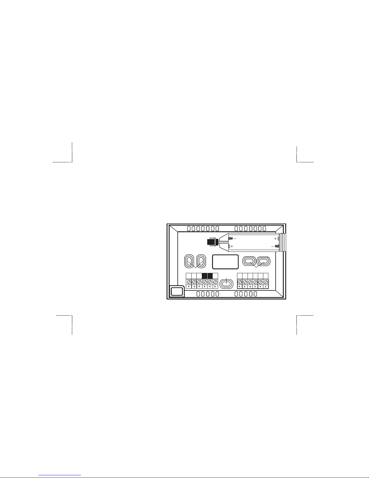
FIGURE 2
7
S2
SC S1
O/B
AUX AUX
Y1 Y2 W1
G R C
WIRE
ACCESS
HOLE
BATTERY
COMPARTMENT
MOUNTING HOLES
MOUNTING HOLES
W2
MOUNTING
HOLE
INSTALLING THE THERMOSTAT
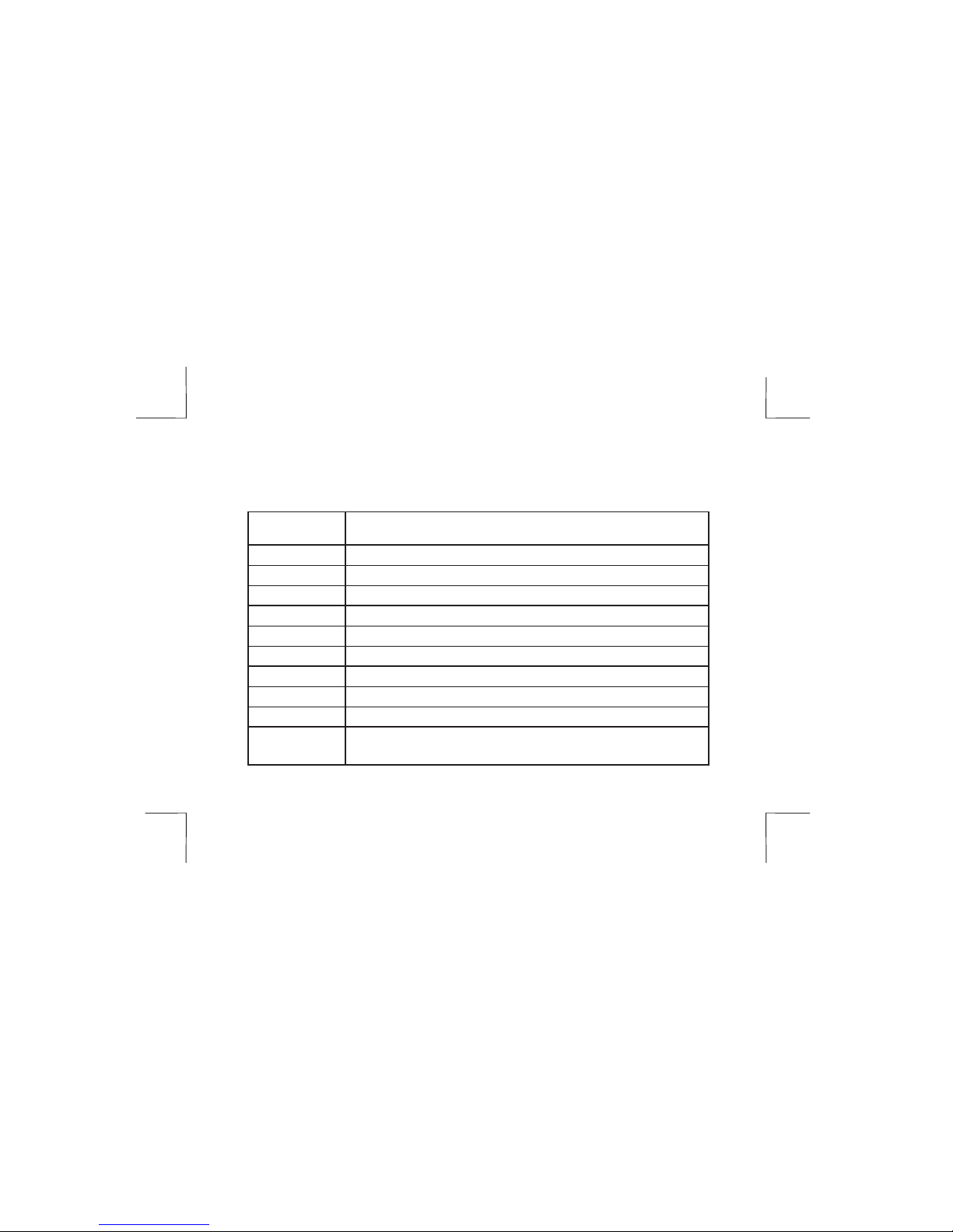
TERMINAL DESIGNATIONS
TERMINAL DESIGNATION
S2 Outdoor Sensor
SC Sensor Common
S1 Indoor Sensor
AUX Auxiliary Contacts
W2/OB Second Stage Heat or Reversing Valve
Y1 First Stage Cool or First Stage Compressor
Y2 Second Stage Cool or Second Stage Compressor
W1 First Stage Heat/Auxiliary/Emergency Heat
G Fan
R 24V AC Hot
C
24V AC Common
8

SETTING THE SYSTEM SWITCHES
The SMART 1000 contains a set of four system switches located on the thermostat
printed circuit board. (Figure 3) The switches are used to match the thermostat
operation and relay outputs with the HVAC system requirements. Refer to the
system switch functions on the next page to properly configure the thermostat.
FIGURE 3
9
1 2 3 4
ON DIP
SYSTEM SWITCHES
. . . . . . . . . . . .

SYSTEM SWITCH FUNCTIONS
Switch 1 - Equipment Type OFF Heat / Cool (Default).
ON For heat pump equipment.
Switch 2 - Fan or When Switch 1 is OFF (Heat Cool Mode)
Reversing Valve OFF Gas Heat - Heater controls fan (Default).
ON Electric Heat -Thermostat calls fan with heat.
When Switch 1 is ON (Heat Pump Mode)
OFF Heat pump ‘O’ reversing valve in cool.
ON Heat pump ‘B’ reversing valve in heat.
.
Switch 3 - Equipment Stages OFF 1 heat / cool gas / electric or 2 heat/1 cool HP.
ON 2 heat /2 cool gas / electric or 3 heat/2 cool HP
Switch 4 - Fossil Fuel Mode OFF Conventional heat pump equipment (Default).
ON Fossil fuel equipment, (Used in the USA mostly)
10
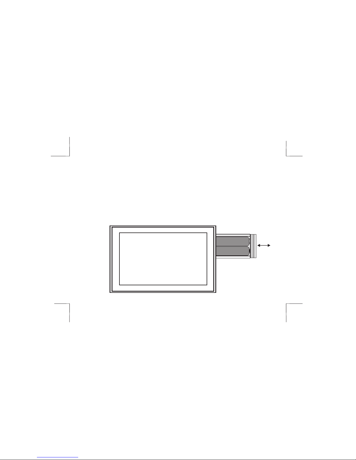
INSTALLING THE BATTERIES
The SMART 1000 comes with two AA batteries. Even if the thermostat is hardwired,
battery backup is recommended to maintain the real-time clock in the event of a
power failure. All other memory is non-volatile in the event of battery or primary
power loss. Press in on the battery access compartment and slide the drawer
out. Install the two AA batteries matching the + and - orientation. Push the battery
compartment in until it clicks shut. When the batteries are properly installed, the
touchscreen display will light up. (Figure 4)
FIGURE 4
+
-
11

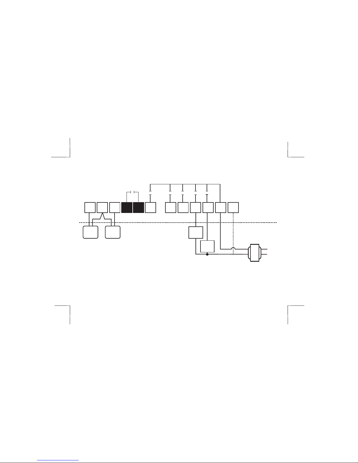
TYPICAL SYSTEM WIRING DIAGRAMS
HEAT ONLY (GAS)
Switch Settings
Switch 1 = OFF Heat/Cool
Switch 2 = OFF Equipment controls fan on call for heat
Switch 3 = OFF Single Stage
Switch 4 = OFF Leave OFF
12
SC
S1
Y1 Y2 W1 G R C
FAN
RELAY
LINE
24 V
W2
O/B
S2
OPTIONAL
REMOTE SENSOR
TERMINALS
THERMOSTAT
EQUIPMENT
OUTDOOR
SENSOR
INDOOR
SENSOR
HEAT 1
RELAY
AUX AUX
(Fan is Optional)
TYPICAL SYSTEM WIRING DIAGRAMS
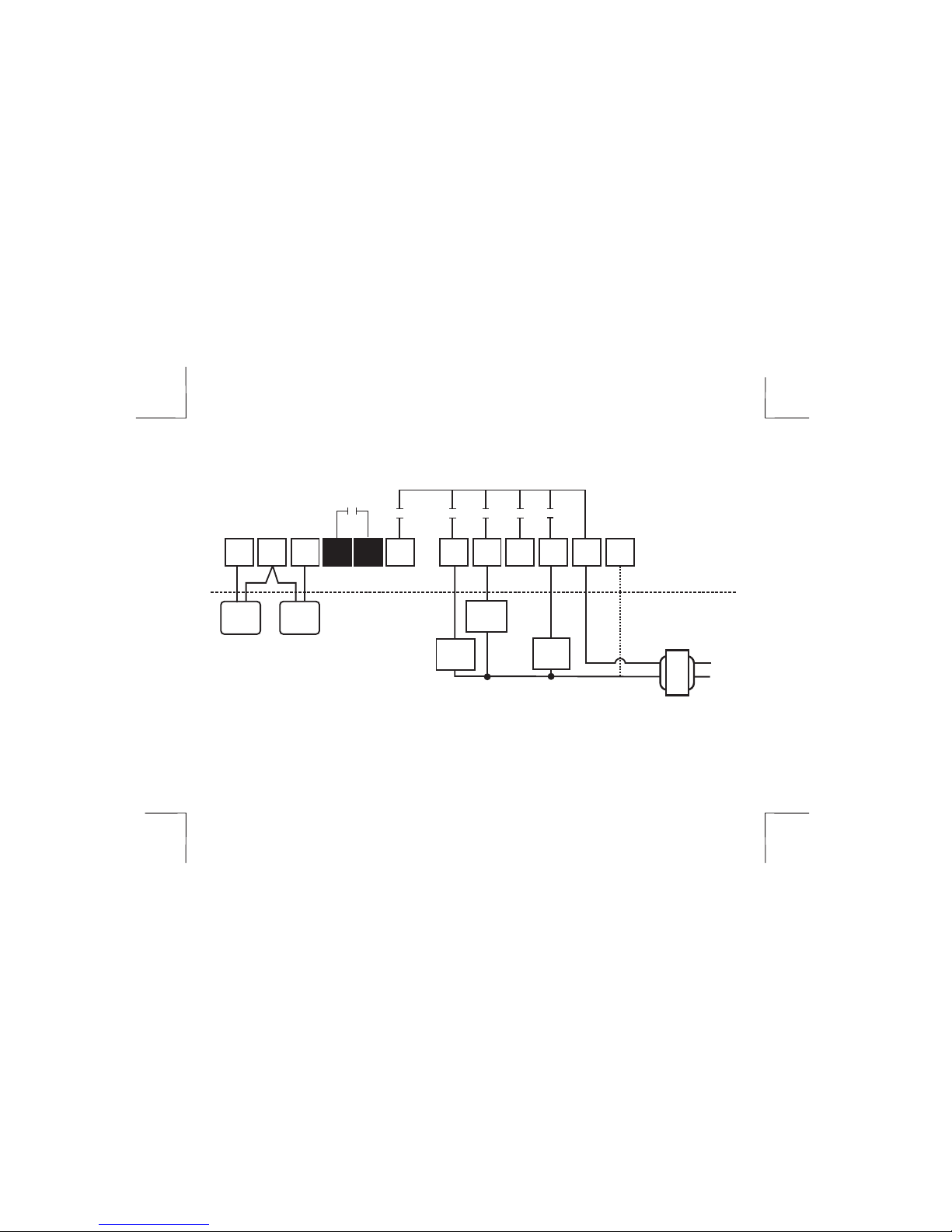
HEAT ONLY (ELECTRIC)
Switch Settings
Switch 1 = OFF Heat/Cool
Switch 2 = ON Thermostat controls fan on call for heat
Switch 3 = OFF Single Stage
Switch 4 = OFF Leave OFF
13
SC
S1
Y1 Y2 W1 G R C
FAN
RELAY
LINE
24 V
W2
O/B
S2
OPTIONAL
REMOTE SENSOR
TERMINALS
THERMOSTAT
EQUIPMENT
OUTDOOR
SENSOR
INDOOR
SENSOR
HEAT 1
RELAY
AUX AUX
TYPICAL SYSTEM WIRING DIAGRAMS
COOL ONLY (SINGLE OR MULTI-STAGE)
Switch Settings
Switch 1 = OFF Heat/Cool
Switch 2 = OFF Fan energized on call for cooling
Switch 3 = OFF/ON OFF = Single Stage ON = Multi-stage
Switch 4 = OFF Leave OFF
14
SC
S1
Y1 Y2 W1 G R C
FAN
RELAY
LINE
24 V
W2
O/B
S2
OPTIONAL
REMOTE SENSOR
TERMINALS
THERMOSTAT
EQUIPMENT
OUTDOOR
SENSOR
INDOOR
SENSOR
COOL 1
RELAY
COOL 2
RELAY
AUX AUX
 Loading...