

Robertshaw SLIMZONE CLASSIC 2701-001, SlimZone Classic 2701-006 Installation And Operation Manual
Page 1
SLIMZONE CLASSIC
2701-001 / 2701-006
ZONE CONTROL SYSTEM
INSTALLATION AND OPERATION
MANUAL
Page 2

TABLE OF CONTENTS
1. INTRODUCTION..........................................................................................................1
1.1 IMPORTANT NOTE.................................................................................................1
1.2 FEATURES..............................................................................................................1
1.3 SAFETY INSTRUCTIONS .......................................................................................1
2. APPLICATION AND DESIGN CONSIDERATIONS ....................................................2
3. COMPONENT REQUIREMENTS................................................................................3
3.1 BASIC SYSTEM......................................................................................................3
3.2 THERMOSTATS ......................................................................................................3
3.3 SIZING TRANSFORMERS......................................................................................3
3.4 SIZING DAMPERS..................................................................................................3
3.5 TYPICAL SYSTEM DIAGRAM ................................................................................4
4. SYSTEM INSTALLATION ............................................................................................4
4.1 REMOVAL AND INSTALLATION OF DOOR ...........................................................4
4.2 INSTALLATION OF BACKPLATE............................................................................5
4.3 THERMOSTAT INSTALLATION ...............................................................................5
4.4 WIRING...................................................................................................................5
4.5 DAMPERS ..............................................................................................................5
4.6 BYPASS DAMPER SYSTEM ..................................................................................6
4.6.1 INSTALLING THE BYPASS DAMPER ....................................................................................6
4.6.2 BAROMETRIC BYPASS SETUP ............................................................................................8
4.6.3 MOTORIZED BYPASS DAMPERS .........................................................................................8
4.7 CURRENT LIMITED OUTPUT TERMINALS ...........................................................8
4.8 HIGH AND LOW LIMITS.........................................................................................8
5. SYSTEM OPERATION .................................................................................................9
5.1 INITIAL POWER UP................................................................................................9
5.2 ESTABLISHING MODE OF OPERATION ................................................................9
5.3 SEQUENCE OF OPERATION .................................................................................9
6. CONTROL PANEL SETUP ........................................................................................10
7. LED STATUS INDICATION........................................................................................11
8. OPERATION CHECK LIST ........................................................................................11
9. SETUP AND TEST.....................................................................................................12
10. TROUBLESHOOTING GUIDE...................................................................................13
11. GLOSSARY ................................................................................................................14
APPENDIX A: LIST OF FIGURES.....................................................................................15
APPENDIX B: LIST OF TABLES.......................................................................................15
WARRANTY.......................................................................................................................16
SlimZone Classic i
Page 3

1. INTRODUCTION
The SlimZone Classic (2701-001/2701-006) zone panel is designed to control conditioned
air in separate zones using a single heating and cooling unit. Model 2701-001 controls up
to 3 zones; model 2701-006 controls up to 2 zones. SlimZone is compatible with both
single stage heating and cooling units and single compressor heat pumps with auxiliary
heat. The temperature of each zone is controlled by its own individual thermostat and duct
mounted motorized damper assemblies which control the distribution of conditioned air
into each zone. All zone thermostats and dampers are wired directly to the SlimZone
Classic control panel. The control panel is wired to the HVAC equipment. Power to the zone
thermostats and motorized dampers is provided by the control panel. A dedicated 24VAC,
75 VA transformer is required to power the control panel.
1.1. IMPORTANT NOTE
IT IS IMPORTANT THAT YOU READ AND UNDERSTAND THIS MANUAL SUPPLIED WITH
THE SLIMZONE
CLASSIC, AS WELL AS THE HVAC EQUIPMENT MANUFACTURER’S INFOR-
MATION, BEFORE INSTALLING THE SYSTEM.
1.2. FEATURES
• Ultra slim styled cabinet [83/4" (22.5cm) W x 91/2" (24cm) H x13/4" (4.5cm) D]
• First call priority method of operation
• Uses conventional 2 to 5 wire thermostats
• LED (light emitting diode) indicators on all system functions
• Solid state logic panel with current limiting outputs
• Controls heat pumps, cooling units, and gas, oil or electric furnace units
• Model 2701-001 controls up to 3 zones. Model 2701-006 controls up to 2 zones
• Controls 1 stage of heating and 1 stage of cooling in heat/cool applications or
1 compressor with auxiliary heat in heat pump applications
• 15 minutes to upstage to auxiliary heat on heat pumps
• 2 or 3 wire damper actuator capability
• All low voltage wiring
• Minimum on/off times of 4 minutes (short cycle protection)
• Minimum on/off time override switch
• Remote mode selector switch capability
• 45 second fan purge into last zone(s) calling
• Slide switch selector to set:
Heat pump or heat/cool
Add-on or normal
Plenum fan control or fan with heat call
Emergency heat
1.3. SAFETY INSTRUCTIONS
• Sudden operation may cause serious injury from moving parts. Leave power disconnected
until installation is complete.
• Sharp edges may cause damage to wires. Use care during the installation.
• Installation must be done in accordance with all local applicable codes and regulations.
• Installer should touch a grounded metal object before handling the SlimZone Classic components and thermostats to avoid potential loss of internal computer programs due to
static discharge.
SlimZone Classic 1
Page 4

2. APPLICATION AND DESIGN CONSIDERATIONS
a. Air conditioning control systems require the air handling equipment be properly sized for
the application; otherwise, satisfactory temperature control may not be realized.
b. Oversizing of HVAC equipment is not recommended. In most cases it is better to slightly
undersize than oversize.
c. Extra consideration should be given in applications that require large amounts of cooling
in cold weather, such as buildings with a center or core area.
d. Hot gas bypass should be considered on some commercial systems.
e. If the HVAC unit is supplied with an economizer, it is recommended that the economizer
package be equipped with a relief air damper.
f. The SlimZone Classic requires the use of motorized zone dampers, such as the A 24VAC 2
wire (powered closed, spring open) or 3 wire (powered closed, powered open) configuration.
g. The pressure drop across typical zone dampers is negligible and normally not a factor
when sizing or calculating branch duct CFM.
h. Typical zone control dampers are designed to work only with low pressure systems (1.0"
WC or less).
i. Balancing dampers should be installed ahead of all motorized zone dampers.
j. Zone dampers should be installed 10ft. (3m) back from discharge grille when possible.
k. Flex or lined duct is recommended on the last 5ft. (1.5m).
l. A bypass damper must be installed on all systems of three (3) zones. Some two (2) zone
systems may require a bypass damper.
m. The thermostats and motorized dampers may be located up to 300ft. (90m) from the
control panel when 18AWG copper thermostat wire is used.
n. This system requires standard electromechanical or electronic heat/cool thermostats. Do
not use heat pump thermostats because a call for compressor from the thermostats will be
recognized by the panel as a cool only call. The control algorithm in this panel is
configured such that heat pump thermostats are not required.
o. The mode of equipment operation at the control panel is first determined by the signals
present on the C and H input terminals of Zone #1, then on the mode of operation of the
zone thermostat(s).
p. To comply with Class 2 wiring code, the maximum load allowed to be switched by the
output terminals is 2.5 Amps.
q. All outputs are protected by a current limiting device.
r. System wires should be tagged to match the panel terminal designations.
s. The addition of equipment heating and cooling limits, as provided by the HILO-200, is
strongly recommended and will greatly help in preventing temperature swings as well as
constant heating/cooling changeover.
t. All zones served by a panel should have the same basic load characteristics.
u. References to typical dampers in this manual are Robertshaw model dampers.
CAUTION
• To avoid short cycling of equipment, always disconnect HVAC equipment from the control
panel before overriding time delay.
SlimZone Classic 2
Page 5
3. COMPONENT REQUIREMENTS
3.1 BASIC SYSTEM
The basic system consists of the main SlimZone Classic control panel and the components
required to support it.
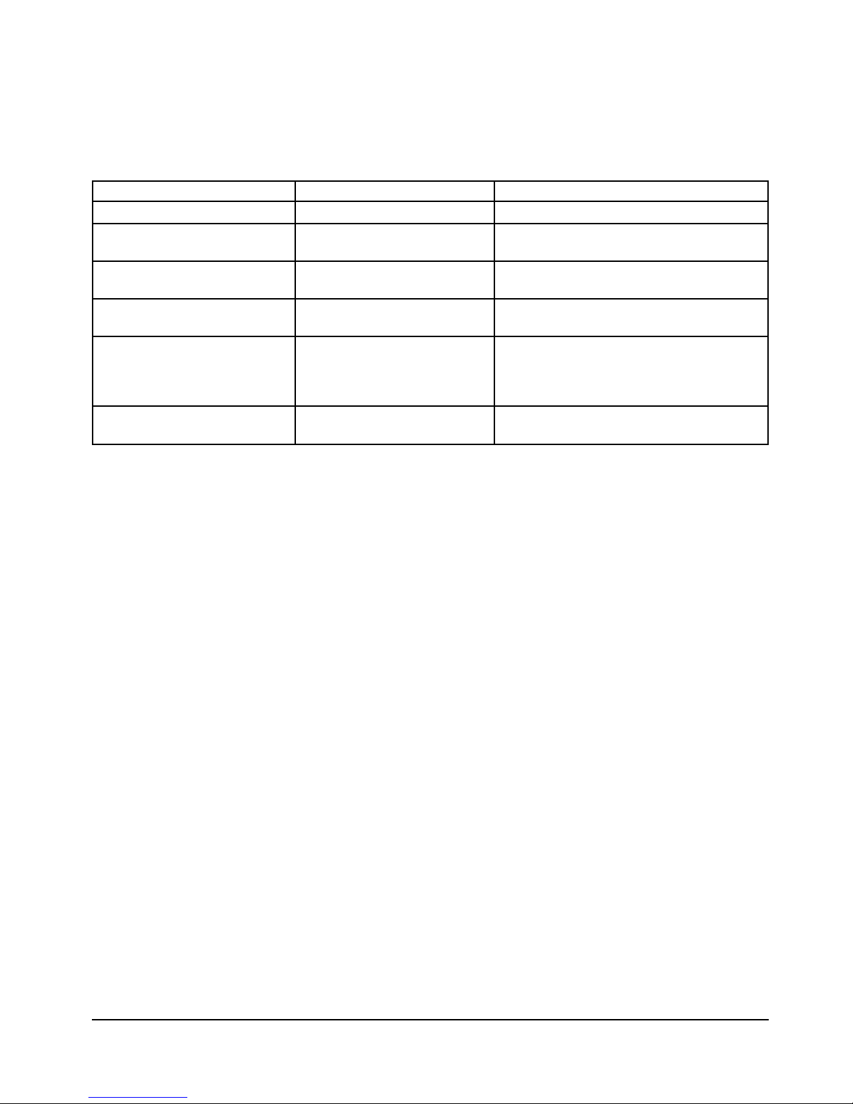
ITEM QUANTITY CONSIDERATIONS
2701-001 or 2701-006 1 controls 3 or 2 zones
4 wire heat/cool thermostat 1 per zone use standard nonshielded 4 conductor
18AWG copper wire
Motorized zone dampers 1 per zone (minimum) use standard nonshielded 2 or 3
(2 or 3 wire) conductor 18AWG wire
Barometric bypass damper 1 BP-10 up to 3 tons capacity or
OR BP-12 5 tons capacity
Motorized bypass damper 1 use standard nonshielded 3 conductor
18AWG wire; requires 24VAC transformer
and static pressure controller (refer to
section 4.6.3)
24VAC transformer 1 for control panel 75 VA; refer to section 3.3 for load
considerations
Table 3.1: SlimZone Classic Component Requirement
3.2 THERMOSTATS
SlimZone Classic requires any conventional electromechanical or electronic 1 heat/1 cool
auto or manual thermostat.
3.3 SIZING TRANSFORMERS
To avoid unsatisfactory operation DO NOT power this control panel with the HVAC
equipment transformer. The rated voltage for the SlimZone Classic is 20-30 VAC, 24
nominal. A dedicated field supplied 24VAC, 75 VA transformer is recommended to power
the control panel, which in turn provides power to the zones including up to a total of 5
dampers. Typical zone dampers require a maximum of 12 VA each. Where damper loads
exceed 5 dampers at 12 VA per damper, install a relay to switch the extra load.
3.4 SIZING DAMPERS
It is important that dampers be sized according to system ductwork specification (CFM)
and balanced in compliance to SMACNA, ACCA and ASHRAE guidelines in order for the
control system to properly control comfort in each zone. Typical dampers are nonmodulating and are available in 2 wire (powered closed, spring return to open), or 3 wire
(powered closed, powered open) configuration. The pressure drop across typical control
dampers is negligible and normally not a factor when sizing or calculating branch duct
CFM. Typical dampers are designed to work with low pressure systems (1.0" WC) or less.
SlimZone Classic 3
Page 6
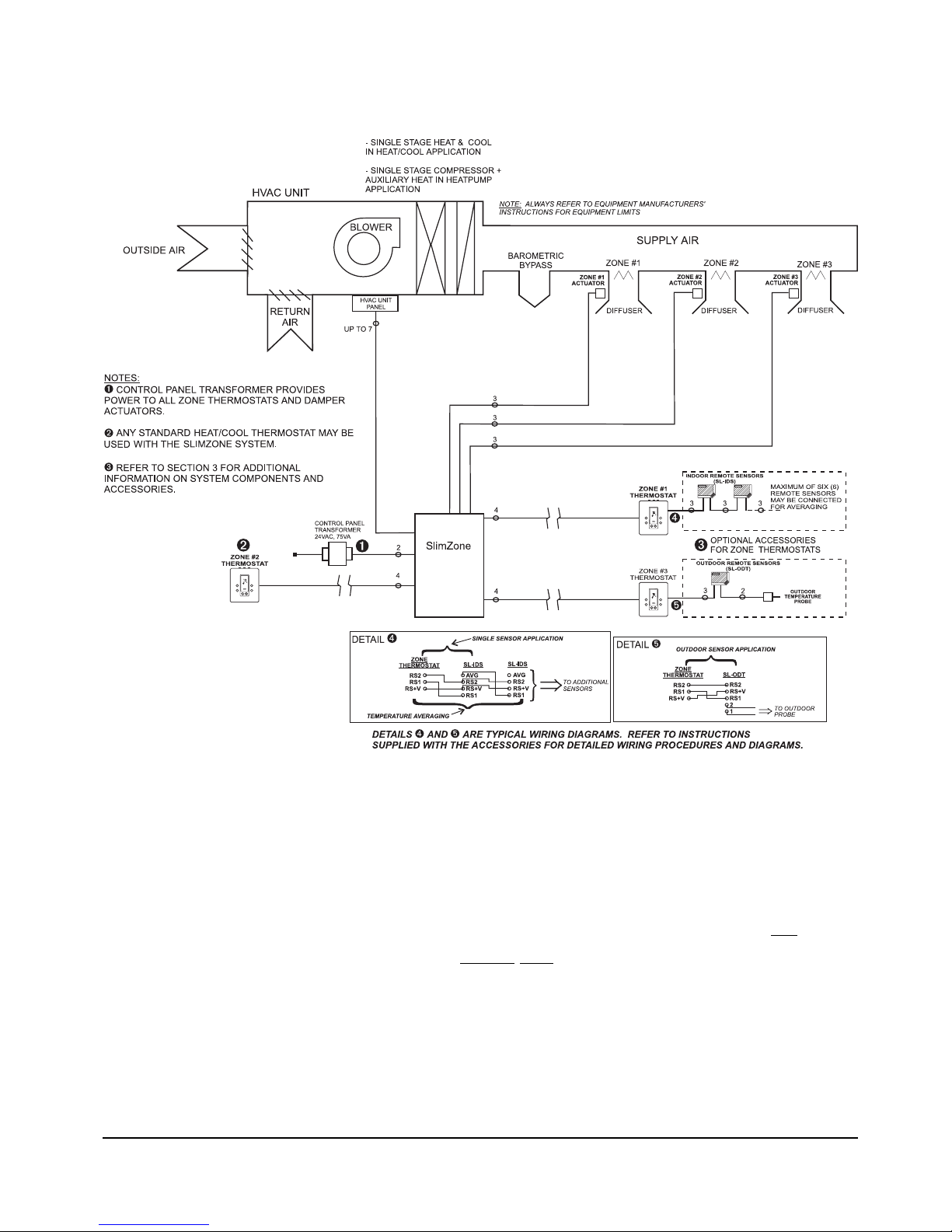
3.5 TYPICAL SYSTEM DIAGRAM
Figure 3.1: SlimZone Classic System Diagram
4. SYSTEM INSTALLATION
4.1 REMOVAL AND INSTALLATION OF DOOR
Installer should touch a grounded metal object before handling the control panel to avoid
potential loss of operation due to static discharge. The door is hinged on the left
side.
Open the door by gently pulling on the bottom
right corner. Apply finger pressure only. The
door may be removed once opened by applying a slight backward pressure. Replace the door
by hooking around the tabs on the left side of the base panel and snapping back into place.
SlimZone Classic 4
Not available
with model
2701-006
Classic
Page 7

4.2 INSTALLATION OF BACKPLATE
The control panel can be mounted on any interior surface. Use the mounting holes (Figure
4.1) to secure in place using the supplied #8 screws. Mount the control panel in a location
that provides easy access for service. Do not mount the control panel on any part of the
HVAC equipment or where moisture may be present. Also, it is strongly recommended that
the panel be installed on a nonvibrating surface. There are several round holes and knockouts for through-the-wall or surface wiring.
CAUTION:
Use proper care when removing upper or lower end cap knock-outs. Apply a sharp rap with
the butt end of a screwdriver to remove knock-outs. Do not use sharp instruments to
remove the knock-outs as internal damage may occur.
Figure 4.1: Backplate Mounting Holes
4.3 THERMOSTAT INSTALLATION
Heat pump thermostats must not be used with the SlimZone Classic panel. Zone
thermostats should be installed in a location that best suits the general load characteristics
of the space it will control. Do not mount thermostats in hallways, exterior walls, or near
cold air returns or registers.
4.4 WIRING
Use #18 AWG (nonshielded) copper wire for all system wiring. Thermostats and damper
actuators may be located up to 300ft. (90m) from the control panel. All system wires
should be tagged to identify thermostat, damper, and equipment wiring. Refer to Figure
4.2 for panel wiring diagram. A spare or third wire should be run between the control panel
and each zone damper in the event that a 3 wire damper actuator is used.
4.5 DAMPERS
Typical dampers are designed to work with low pressure systems (1.0" WC or less).
Balancing dampers should be installed ahead of all zone dampers. Zone dampers should
SlimZone Classic 5
Page 8

be installed 10ft. (3m) back from discharge grille. A flex or lined duct is recommended for
the last 5ft. (1.5m). Robertshaw dampers are 2 position dampers. Two wire dampers are
powered closed and spring return open. Three wire dampers are powered closed and
powered open. For applications requiring minimum air ventilation, an adjustment screw is
available to set the damper to a specified minimum open position. Robertshaw dampers
are shipped from the factory with the minimum position adjustment screw in the fully
closed position; allow for 3% to 5% leakage with damper closed. The control panel has 3
terminals for each damper which are (refer to Figure 4.2):
PC: power damper closed
X: common
PO: power damper opened
Power to the dampers is provided by the panel.
NOTE: High ambient temperatures (e.g., those found in an attic), will have an impact on the
current capabilities of the panel and the number of zone dampers that can be connected to
the panel. The 2701-001 and 2701-006 are powered by a single 75 VA transformer. This
transformer is used to power the panel, thermostats and motorized dampers. The ambient
temperature will have an impact on the Polyfuse current limiting protection. The maximum
number of dampers that can be connected to the total system using Robertshaw dampers are:
At 25ºC (77ºF) At 40ºC (104ºF)
6 E Series dampers 5 E Series dampers
5 E2 Series dampers 4 E2 Series dampers
6 E3 Series dampers 5 E3 Series dampers
If additional dampers are required you must use a relay to energize these additional
dampers from an independent source.
4.6 BYPASS DAMPER SYSTEM
In order to maintain proper air flow and static pressure throughout the HVAC system, a
bypass system should be used. In some 2 zone applications a bypass damper may not be
required. This is based on duct sizing where either zone is able to handle approximately
75% of the total system CFM (cubic feet/minute). This will result in only slightly higher air
velocity at the discharge grille if only one zone is calling and yet allow for proper CFM
across the cooling coil. In many smaller commercial and most residential zone systems, a
barometric bypass damper is all that is required to maintain proper system static pressure.
In larger systems, a motorized bypass damper with an independent static pressure control
will be required.
4.6.1 INSTALLING THE BYPASS DAMPER
The bypass damper must be installed in the main supply plenum in a straight section of
equal duct size. The bypass air may be discharged into the return air plenum or above the
ceiling, if this area is used as a common return.
SlimZone Classic 6
Page 9

Figure 4.2: SlimZone Classic Panel Wiring Diagram
SlimZone Classic 7
ROBERTSHAW
Zone 3
2701-006
not available on
TIME DELAY
OVERRIDE
Page 10

4.6.2 BAROMETRIC BYPASS SETUP
The BP-10 and BP-12 barometric bypass dampers may be installed in a vertical or
horizontal (up flow or down flow) position. Refer to the installation instructions provided
with the dampers for further information. To set the damper to proper relief control, open
all zone dampers by selecting constant fan on all zone thermostats. Adjust the balancing
mechanism so that the damper blade hovers on the closed position. Lock the balancing
mechanism. If the system has been properly balanced, the barometric bypass damper will
maintain proper system air pressure. As zone dampers close, the bypass damper will open
to relieve excess static pressure.
4.6.3 MOTORIZED BYPASS DAMPERS
Some systems may require a motorized bypass damper. Robertshaw 3 wire bypass dampers
are independently controlled by the Robertshaw EPC-602 static pressure regulator. Mount
the EPC-602 in a position so that the LEDs (light emitting diodes) are visible for checking
operation, and mount the bypass damper so that it is accessible for wiring. Refer to the
installation instructions provided with the EPC-602 for further information.
4.7 CURRENT LIMITED OUTPUT TERMINALS
All output circuits on the SlimZone Classic control panel incorporate a self-resetting current
limiting device which provides protection against excessive current draws caused by
circumstances such as wiring shorts on an output. This device, referred to as a polyfuse,
is activated in general when the current draw exceeds 2.5 Amps. The value and the
duration of the excess current is taken into account. The polyfuse will allow excess
currents of very short duration (i.e., spikes) in order to prevent circuit interruption by noisy
lines or occasional minor surges. In its current limiting mode, the polyfuse reduces the
output current to milliamps.
NOTES:
• The low leakage current may be sufficient to produce a small voltage reading when
measured with a volt meter with a high input impedance.
• The panel turns ON the FAULT LED (red) when excess current is being drawn from an
output to warn the user.
When the cause of the excess current has been removed and the current draw is returned
to a value below 2.5 Amps, the polyfuse will reestablish full output current; in some
instances this may take up to 20 seconds. The polyfuse eliminates the need to replace
blown fuses.
4.8 HIGH AND LOW LIMITS
When bypassing conditioned air it is important to consider high and low limit control to
prevent coil freeze up or overheating. An independent high and low limit control is
recommended to protect the HVAC equipment from these conditions. Although there is no
high or low limit control incorporated in the SlimZone Classic control panel, the HILO-200
can be adapted to meet this need. Refer to the installation instructions provided with the
HILO-200 or contact technical services for further information.
SlimZone Classic 8
Page 11

5. SYSTEM OPERATION
5.1 INITIAL POWER UP
When first powered up, the control panel will immediately process any fan calls from the
zone thermostats but will ignore any heating or cooling calls for a maximum delay of 4
minutes. After the 4 minute minimum off delay has been satisfied, the control panel will
then accept heating or cooling calls from the zone thermostats.
5.2 ESTABLISHING MODE OF OPERATION
The equipment mode of operation (HEAT, COOL, AUTO) is determined according to the
signals present at the C and H terminals at the Zone #1 input on the control panel (Figure
4.2). The C and H input signals take precedence on any other signals from the zone
thermostats. The mode is established according to the following sequence:
Input signal
present on: Mode of Operation Functionality
C COOL ONLY Only cool calls answered; heat calls ignored
H HEAT ONLY Only heat calls answered; cool calls ignored
no signals AUTO All calls answered; panel is in *First Call Priority mode
Table 5.1: Mode of operation
* In the First Call Priority mode, first call for heating or cooling will establish the mode of
equipment operation.
5.3 SEQUENCE OF OPERATION
Once the heating or cooling mode is established and a call for that mode has been
received by the panel, the control panel will energize the proper damper relays to allow the
conditioned air into the calling zone(s). The panel will close any zone dampers not
matching the established mode of operation. Fan call inputs will be ignored by the panel.
The control panel will keep the equipment operating in the established mode for a minimum
on time of 4 minutes and until all zones calling for the established mode of operation are
satisfied. Once all zones are satisfied, the control panel will de-energize the equipment and
will initiate a minimum off timer of 4 minutes to prevent equipment short cycling. The
control panel will continue to operate the fan for a period of 45 seconds to purge
conditioned air into the last zone(s) calling. After the purge cycle, the panel will perform
the following: 1) if no zone thermostats are calling for constant fan, all zone dampers will
be opened and the fan relay de-energized to allow for any hard wired low speed fan
distribution of air into all zones; 2) if any zone is calling for constant fan, the control panel
will keep the fan relay energized and open all zone dampers.
When the SlimZone Classic control panel is in the AUTO mode of operation (no input
signals on C and H Zone #1 terminals), it operates on a first call priority. As described
above, the control panel searches the zone thermostats looking for heating or cooling calls.
When a mode of operation has been established, the panel will operate in that mode. If
during this time an opposite call is received, the panel will continue with the established
mode of operation until the initial call(s) has been satisfied, the purge cycle has been
completed and the 4 minute delay timer will be initiated. If after the 4 minute delay, the
control panel is receiving a call for the opposite mode, it will change mode of operation to
satisfy the new calls as described above.
SlimZone Classic 9
Page 12

The following sequence is only applicable when the SlimZone Classic system is used in
heat pump applications and the system is in the HEAT ONLY or AUTO mode of operation.
The auxiliary heat in heat pump systems is controlled by an internal control panel timer.
Whenever the heat pump is in the heating mode, the control panel will energize the auxiliary
heat output if the heating call is not satisfied within 15 minutes. Once the auxiliary heat is
energized, it will remain on until the heating call is satisfied.
When the control panel is used with an add-on heat pump, it will ensure that the
compressor is de-energized whenever the auxiliary heat is energized. This eliminates the
need for fossil fuel kits. In the event of a heat pump compressor failure, emergency heat
is activated through an EH switch located on the control panel (Figure 4.2, Table 6.2).
When the switch is placed in the EH position, the Y1 terminal output to the compressor will
always be de-energized and the W1 terminal will automatically replace the function of Y1.
The upstaging sequence will be canceled and any call for heating will energize W1.
6. CONTROL PANEL SETUP
For heat/cool systems (gas, oil or electric), the control panel slide switches have the
following functions:
Switch # Position Description
1 OFF (down) establishes that the system is in the HEAT/COOL mode of operation
2 OFF (down) fan controlled by plenum thermostat
ON (up) fan ON immediately with heat calls (for electric furnaces)
3 N/A switch has no function in HEAT/COOL application; leave OFF
Table 6.1: Switch functions in heat/cool systems
For heat pump applications the control panel slide switches have the following functions:
Switch # Position Description
1 ON (up) establishes the system is in the HEAT PUMP mode of operation
2 OFF (down) standard heat pump system
ON (up) ADD-ON system
3 OFF (down) normal operation
ON (up) Emergency Heat operation (EH)
Table 6.2: Switch functions in heat pump systems
SlimZone Classic 10
Page 13

7. LED STATUS INDICATION
All relay outputs and system status can be verified at the control panel and are indicated
by LEDs (light emitting diodes). Refer to Figure 4.2 for location of the LEDs.
REFERENCE COLOR LOCATION FUNCTION
POWER ON Green 24VAC terminal Panel is powered
FAULT Red 24VAC terminal Short in system
ZONE 1 Green Zone 1 terminal Damper open
ZONE 2 Green Zone 2 terminal Damper open
ZONE 3 Green Zone 3 terminal Damper open
G Green Equipment terminal Fan relay energized
Y1 Yellow Equipment terminal Cooling/compressor relay energized
W1 Orange Equipment terminal Heating relay energized
B Orange Equipment terminal Reversing valve relay energized in heating
NORMAL WHEN Green Upper right corner Panel functioning properly
FLASHING
Table 7.1: LED Description
8. OPERATION CHECK LIST
Verify that the following controls have been properly configured, installed and adjusted.
1. High limit
2. Low limit
3. Static pressure or barometric bypass damper
4. All thermostats low setpoint at 68°F (20°C) and high setpoint at 76°F (24°C)
5. Tag all wiring and system components to correspond to the zone they serve
6. If HVAC unit incorporates an economizer, it is important that it be checked for proper
operation and that the minimum positioning stop be set.
7. If the HVAC unit has an economizer that is not equipped with a relief damper, it may be
necessary to relink the return air damper so that it will always remain thirty percent (30%)
open, otherwise the bypass damper system may not perform properly.
SlimZone Classic 11
Page 14

9. SETUP AND TEST
1. Disconnect power to the equipment before pushing the time delay override button.
2. Cooling Cycle: Set the cooling setpoints of all zone thermostats to their lowest setting.
Note: Ensure that the remote switch selector for mode of operation is not
set to Heat Only (if installed).
a. Press and hold time delay override button. The time delay override is in effect only
when the time delay override button is depressed.
Note: In the time delay override mode, the time factors are reduced by 60 times
(i.e., 1 minute is reduced to 1 second).
b. The LEDs located on the SlimZone Classic panel should indicate the following
condition:
System power ON
Cooling ON
Fan ON
All zone dampers open
3. Heating Cycle: Set the heating setpoints of all zone thermostats to their highest setting.
Note: Ensure that the remote switch selector for mode of operation is not
set to Cool Only (if installed).
a. The LEDs located on the SlimZone Classic panel should indicate the following
condition:
System power ON
Heating ON
Fan ON (except when plenum option is selected)
R.V. ON
All zone dampers open
4. Reconnect power to the equipment once test is completed.
5. Restore zone thermostats to normal setpoints.
SlimZone Classic 12
Page 15

10. TROUBLESHOOTING GUIDE
PROBLEM POSSIBLE CAUSE SOLUTION
No heat/cooling in Zone thermostat(s) Set COOL/OFF/HEAT switch on the
house thermostat(s) to the proper setting.
Faulty heating/cooling equipment Troubleshoot equipment according to
manufacturer’s instructions.
Faulty thermostat Troubleshoot equipment according to
manufacturer’s instructions.
Replace if necessary.
Faulty zone control panel Follow instructions outlined in Setup
and Test. Replace if necessary.
Improper remote switch selector Ensure the switch is set to a mode of
setting (if installed) operation which allows the requested
call to be serviced.
No heat/cooling in Balancing damper closed Check all balancing dampers in the
zone same duct as the motorized zone
damper; closed balancing dampers
should be readjusted.
Zone registers closed Check all zone registers; closed
registers should be readjusted.
Faulty thermostat Troubleshoot thermostat according
to manufacturer’s instructions.
Replace if necessary.
Faulty zone control panel Follow instructions outlined in Setup
and Test. Replace if necessary.
SlimZone Classic 13
Page 16

11. GLOSSARY
Auxiliary/Emergency Applies to heat pump applications only. If the call for heat is not satisfied
Heat within 15 minutes, auxiliary heat is energized and will remain on until the
call is satisfied. In the event of a heat pump compressor failure,
emergency heat (EH) is activated through an EH switch located on the
control panel.
Bypass System A bypass system maintains uniform static pressure in the system ductwork
by modulating a motorized bypass damper in the main supply duct.
Mode of Operation A mode is a specific operating setting (Off, Cool, Heat, Auto, E Heat)
which can be established at the control panel and the zone thermostats.
Zone A defined area that is controlled by a zone thermostat and motorized
zone damper. Zone thermostats request heating or cooling from the SZC
control panel, which in turn controls the HVAC equipment and zone
dampers accordingly.
SlimZone Classic 14
Page 17

APPENDIX A: List of Figures
FIGURE 3.1: SLIMZONE CLASSIC SYSTEM DIAGRAM.................................................4
FIGURE 4.1: BACKPLATE MOUNTING HOLES...............................................................5
FIGURE 4.2: SLIMZONE CLASSIC PANEL WIRING DIAGRAM .....................................7
APPENDIX B: List of Tables
TABLE 3.1: SLIMZONE CLASSIC COMPONENT REQUIREMENTS ..............................3
TABLE 5.1: MODE OF OPERATION..................................................................................9
TABLE 6.1: SWITCH FUNCTIONS IN HEAT/COOL SYSTEMS.....................................10
TABLE 6.2: SWITCH FUNCTIONS IN HEAT PUMP SYSTEMS.....................................10
TABLE 7.1: LED DESCRIPTION......................................................................................11
SlimZone Classic 15
Page 18

WARRANTY
Limited Two Year Warranty
The manufacturer warrants to the original purchaser that its product and component parts will be
free from defects in workmanship and materials for a period of two years from the date of
purchase. Your dealer will provide free replacement of your panel upon proof of purchase.
Exclusions
This warranty does not apply in the event of misuse, abuse or as a result of unauthorized
alterations or repairs. The manufacturer will not be liable for any consequential damages including,
without limitation, damages resulting from defects, loss of use, or misuse.
Compliance
• This equipment, if installed in strict accordance with the manufacturer's instructions, complies
with the limits for a Class B computing device pursuant to Subpart J of Part 15 of FCC rules.
• This equipment, if installed in strict accordance with the manufacturer’s instructions, complies
with CE rules.
SlimZone Classic 16
Page 19

SlimZone Classic 110-901D
Climate Controls Americas
515 South Promenade Avenue
Corona California 92879-1736 USA
Customer Service Telephone +1 800 951 5526
Customer Service Facsimile +1 630 260 7299
iccacustomerservice@invensys.com
For Technical Service
Telephone +1 800 445 8299
Facsimile +1 630 260 7243
technicalservice@invensys.com
www.icca.invensys.com
©2004 Invensys Climate Controls Americas
Climate Controls of Canada, Inc.
3505 Laird Road Unit #14
Mississauga Ontario L5L 5Y7 Canada
Customer Service Telephone +1 800 387 7978
Customer Service Facsimile +1 905 828 1265
iccacustomerservice@invensys.com
 Loading...