

Page 1
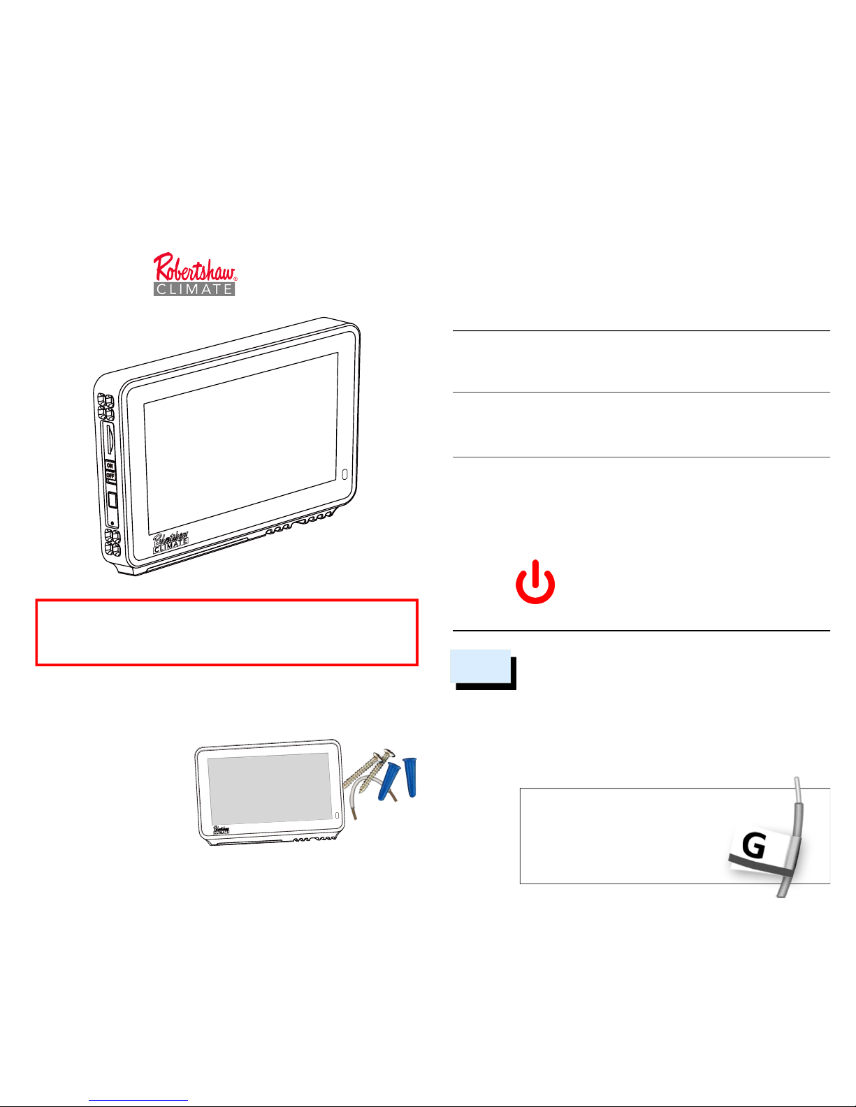
- Wi-Fi Thermostat Model RS7210
- Two screws and anchors
- Wire labels
- Jumper wire
- User manual
In the Box
For 24V-AC Thermostat Wiring
Installation & User Manual
RS7210
Before removing the wires from the thermostat or wall
plate, take a photo of all wires for reference, then label
each wire according to the terminal codes.
Disconnect the wires from the old thermostat one by one.
Do not let any wires fall back into the wall. Remember,
the power to your HVAC system must be turned off.
After labeling the wires, we recommend
securing them to an object such
as a pen or clip to prevent them
from falling back into the wall.
Remove the Old Thermostat
1
Please turn off the furnace’s main power at the switchbox
before beginning the installation process.
POWER OFF
Warning: Failure to turn off power
may result in electrical shock and/or
system damage.
Turn Power Off
This thermostat is designed to work on most 24V low voltage
heating and cooling systems such as gas and oil furnaces, heat
pumps, and single-stage systems
Professional installation recommended for:
• Dual fuel systems (heat pump with furnace)
Getting started
For conventional (gas/oil/electric) and heat-pump systems
>
2-Heat & 1-Cool > Heat Only > Cool Only
* C-Wire required to power the thermostat
Check Compatibility First
Warning: Failure to follow and read all instructions
before installing or operating this device may cause
personal injury and/or property damage.
PAGE 01 PAGE 02250064-00
Some features require an internet connection and a user account. Features,
specifications, and appearance are subject to change without notice.
Page 2
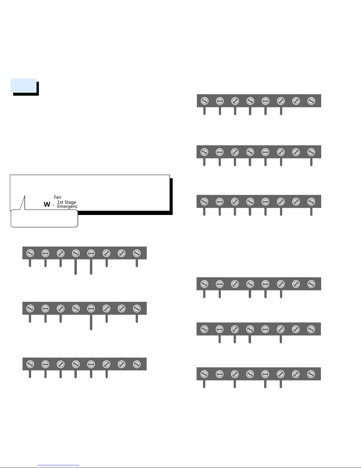
RC - Power Cooling
RH - Power Heating
G - Fan
W -
1st Stage Heating
Emergency heat
Y - 1st Stage Cooling
C - Common
O/B - Reversing Valve
W2 - 2nd Stage Heating
( )
........
........
......
Remove jumper wire if you
have both RC & RH wires
The following are typical wiring diagrams for common systems:
Insert all wires vertically from the open socket into the proper terminal.
Ensure each wire is inserted into the matching terminal (refer to the
photo taken previously if needed). Pull wires gently to ensure wires are
securely fastened.
When all wire connections have been completed, place any surplus
wires back inside the wall.
*For the heat pump system, if the old thermostat has separate wires for
Aux-Heating and Emergency-Heating, twist the wires together and
connect them to the W terminal.
Warning: Use caution when securing and routing wires
to prevent possible short to adjacent terminals.
Connect the New Wall Plate
2
Heat Pump with Emergency Heating
RC RH G W Y C OB/W2
........
24V
Fan
Compressor
Aux/Emer Heat
Common Reversing
Valve
Factory
Installed
Jumper
Heat Pump without Emergency Heating
RC RH G W Y C OB/W2
........
24V Fan
Compressor
Common Reversing
Valve
Factory
Installed
Jumper
Conventional Heating/Cooling system with C wire
RC RH G W Y C OB/W2
........
24V Fan Heat Cool
Common
Single
Transformer
Factory
Installed
Jumper
Conventional Heating/Cooling system with C wire
RC RH G W Y C OB/W2
24V
Cooling
24V
Heating
Fan Heat Cool
Common
Dual
Transformer
You may substitute the C wire with a spare wire if one is available.
Conventional 2nd Stage Heating
RC RH G W Y C OB/W2
........
24V Fan
CommonCool 2nd Stage
Heat
1st Stage
Heat
Single
Transformer
Factory
Installed
Jumper
Conventional 2nd Stage Heating
RC RH G W Y C OB/W2
24V
Heating
24V
Cooling
Fan
Common
2 Transformers
Heat & Cool
Cool 2nd Stage
Heat
1st Stage
Heat
1) At the thermostat, connect C with the G wire;
2) At the furnace’s wiring terminal, move the G wire to the C terminal,
then use the included jumper wire, G with Y for cooling or G with W for heating.
3) With this configuration the thermostat will have no fan control.
Conventional system without the C or spare wire
(also commonly called a 4-wire system)
RC RH G W Y C OB/W2
........
24V
CommonHeat Cool
Factory
Installed
Jumper
Heat only 3-Wire system
RC RH G W Y C OB/W2
........
24V
CommonHeat
Cool only 3-Wire system
RC RH G W Y C OB/W2
................
24V
CommonCool
PAGE 03 PAGE 04
Page 3
If you have done everything correctly, your thermostat
should power on and prompt you to start the setup.
Now, enjoy the savings and comfort of owning one of
the industry's best smart thermostats! The Robertshaw
Climate RS7210.
Ensure the C-wire is properly connected to the furnace
and thermostat. Properly secure and lock the furnace
door into place. Switch the power back on for the
heating/cooling system at the main switch box.
Power On and Enjoy!
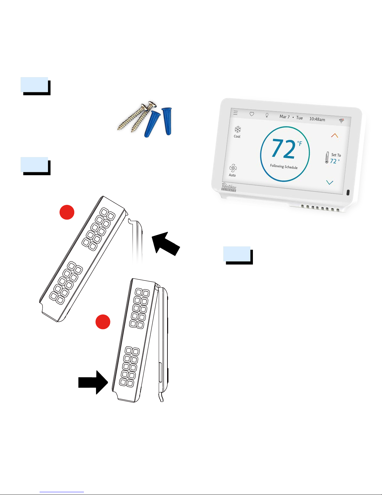
5
clips
1
push
2
Firmly press forward to
secure it into position.
First, align the two clips on the back of the
thermostat into the corresponding slots on
the top of the wall plate.
4
Attach to the Wall
Use the enclosed screws and anchors
to mount the new wall plate. In most
cases, you can utilize the same
mounting position of your old
thermostat. Be sure to check the
alignment of your wall plate pre and
post installation of the thermostat unit.
Mount the New Wall Plate
3
PAGE 05 PAGE 06
Page 4
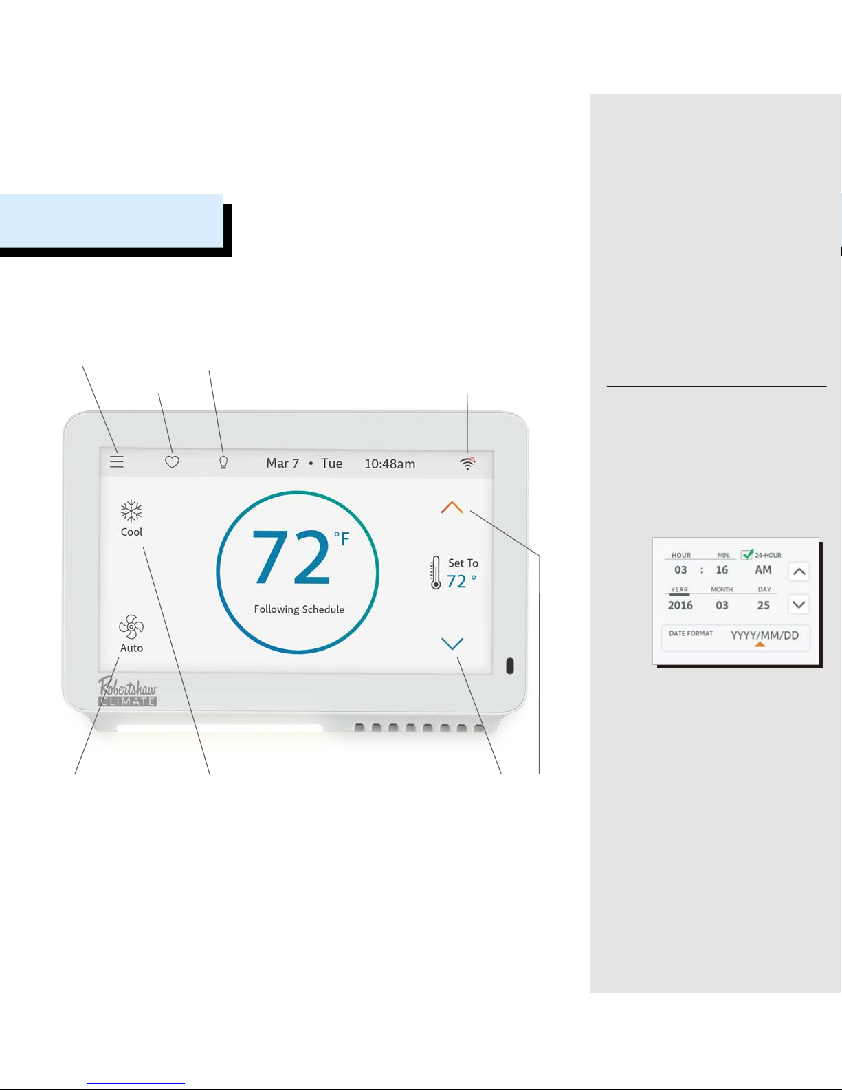
EZ Comfort
Nightlight
Main Menu
Operation Mode
Wi-Fi Setup
Temperature
adjustment
Fan Status
Main Screen
1. Date, Time
ON THE DEVICE: Though there is no
restriction for any date and time you
set as current, please enter your
location’s current date and time to
avoid any confusion; once the device is
registered or linked to a user account,
the date and time on the device will
automatically update to the current
time associated with the user account.
APP or WEBPAGE: The date and time
for the device as well as the user
account will automatically update by
selecting the time zone for the device.
Time
Date
Date
Format
For a quick and easy way to begin
using your new smart thermostat,
the device will automatically direct
you to the Initialization Setup process
once it’s turned on for the first time.
Initialization
PAGE 07 PAGE 08
Page 5

Date & Time
Menu -> Settings -> Date & Time
Heating Type
Menu -> Settings -> Advanced -> Equipment Type
Mode
Mode Icons on Main Screen
Wi-Fi Setup
Wi-Fi Icon on Main Screen
MENU
ACCESS
You must have a proper Wi-Fi connection in order to access smart
features such as App remote access, weather forecast and more.
Please follow the on-screen instructions to complete the Wi-Fi
setup. More information on Wi-Fi connections can be found on
the next page.
After a successful connection, the a message that the device has
not been registered by any user will be shown. You can now add
the device to a user account after downloading the App and
setting up an account.
4. Wi-Fi Setup
Off
CoolHeat
Auto
Tap the Mode icon on the main screen to switch between modes:
3. Mode
Please check your heating and cooling system manual or
consult with a professional HVAC technician if you do not
know which option to select.
This thermostat doesn’t support Fan-Coil systems.
Heat Pump system? You must also select Cool or Heat for
the mode in which the reversing valve is energized.
Select your home’s heating type from the options available:
Gas/Oil/Propane, Electric, or Heat Pump
2. Heating Type
PAGE 09 PAGE 10
Page 6

1) Wi-Fi signal is too weak or IS ON A 5G network?
2) SSID contains spaces or non-ASCII characters;
3) Incorrect password;
4) Wi-Fi is okay but your internet is unavailable;
5) Requires additional webpage authentication.
?
The following may cause a failed connection to the device:
If no password is required, press OK to continue.
For an unregistered device, it will
display the message that the device
needs to be registered.
Follow the instructions on the next page
to add the device to your account
after downloading the App and
setting up an account.
Elizabeth21
After a successful connection, an account ID for the network
device will appear.
Wi-Fi Connection
Scan
Available
Wi-Fi Networks
(SSID)
Cap
Letters
Numeric or
Special
Characters
Wi-Fi can be manually turned off or on. Turning off your Wi-Fi will
also disable the internet connection and all smart features,
including App access to the device.
Wi-Fi
ON
Turn on Wi-Fi to enable smart
features for this device.
Not connected
to your Wi-Fi.
Internet is
not available.
Tap the Wi-Fi icon to enter the Wi-Fi setup screen,
then tap the Scan icon to generate available Wi-Fi
networks. Follow the on-screen instructions to complete the Wi-Fi setup.
SCAN
If your device loses connection with your wireless network, it will
automatically attempt to reconnect after five minutes. If that fails,
it will make a new attempt every 15 minutes for the next 24 hours.
Any manual operation of the thermostat will stop automatic
reconnection attempts.
Auto Reconnect
Wi-Fi Setup
PAGE 11 PAGE 12
Page 7

Members of a family need to share an account in
order to gain access to the thermostat.
http://www.robertshawclimate.com/thermostats/rs7000-series-new
After installing the App onto your smart phone or tablet, create a
user account. The user account can also be created through the
home page on our website.
Step 2: Create a User Account
There are three ways to download the App for
your Smart Device:
1) Search RS7000 in the App Store or the Google
Play Store, then download.
2) Use your smart device to scan the QR code on
the left, then click on the iOS or Android link to
download.
3) Go to www.robertshawclimate.com/
thermostats/rs7000-series, then click on the iOS
or Android link to download.
iOS / Android
App Download
Step 1: Download
App Setup
Congratulations! You are now
ready to use the thermostat.
Now set up your App to enjoy
exciting smart features.
The MAC ID is a unique network ID for this device; this
helps to identify your device over the internet.
The Temporary Verification Code (TVC) is a 4-digit code
that is randomly generated each time you enter this
screen. It expires after 90 seconds, upon which a new one
will be needed.
During technical support, the TVC also functions as the
verification of “the user currently in possession of the
device“.
Tap the TVC code to
generate a new one when
the previous code expires.
Once the device is connected to the
internet, you’ll be able to read the
Temporary Verification Code (TVC)
and MAC ID from the Wi-Fi Status
screen.
MAC-ID and Verification Code
Log in to your account: tap ”Add
Device” on the device list screen,
then simply follow the on screen
instructions on the App or Webpage
to complete this task. You will be
asked to enter the MAC-ID and
the Temporary Verification Code.
Wi-Fi Status Screen
Step 3: Add Device to your Account
> Main Menu
> Wi-Fi Connection
> Registration Info.
MENU
ACCESS
PAGE 13 PAGE 14
Page 8

You can opt to turn the System Off to shut down
all HVAC operations including fan operation.
Please note that your device is always “running a program” and the current
operation mode is part of that program. Thus, changing the current mode
will also update the mode setting in the current program.
On the Main Screen, tap the mode icon
on the upper left to switch between Cool,
Heat, Auto, and Off settings.
OffCoolHeat Auto
System
Modes
Mode Setup
1) Tap a day of the week;
2) Scroll left and right to the column you
want to change;
3) Simply drag the color bar up or down
to change the temperature;
4) To create a new setpoint, tap on a time
column, then move the rest of the
color bar section up or down;
5) To delete a setpoint, merge the color
bar with the one before or after.
From the main menu in the App, select Schedule:
Scheduling with the App
+1
-1
You can override the current schedule
by tapping the color-bar to adjust
the temperature. This is a termporary
adjustment, meaning that the override
expires when the next schedule
begins. Tap the lock icon to permanently hold the setting.
Temporary Adjustment
Schedule
PAGE 15 PAGE 16
Page 9

PAGE 17 PAGE 18
Robertshaw Climate-Home
Webpage Schedule
Log in to your account on the Webpage,
select Schedule from the user menu:
1) Select a schedule, then tap a day;
2) Scroll left and right to the column
you want to change;
3) Simply drag the color bar up or down
to change the temperature;
4) To create a new setpoint, tap on
a time column, then move the rest
of the color bar up and down;
5) To delete a setpoint, merge the color
bar with the one before or after.
68°
Scroll Time
°F
VIEW: View the schedule in either Graphic or List View.
SET: Set up specific setpoints (temperature and time).
COPY: Copy the setpoints to other days of the week.
System Menu -> Schedules
Schedule on the Thermostat
Schedule List:
There are only two default schedules available for selection when the
device is offline. Please follow the instructions on the App or
Webpage to create a new schedule or to delete an existing one.
DELETE
INSERT
Select a period (total of 8 available per day) to change.
Set Starting Time increments in 15-minute intervals.
Select desired temperature or system Off for the period.
Insert a new period before the current one.
Delete the current period, merging the time with the
next period.
Schedule Steps:
STEP 1:
STEP 2:
STEP 3:
PAGE 17 PAGE 18
Page 10

*If the G wire was substituted for the C wire during installation,
the Fan-On & Circulation options will not function.
Auto
On
Circulation
Fan will follow heating and cooling operations.
Fan runs non-stop until either 'Auto' or
'Circulation' have been selected.
Fan runs on and off regularly in addition to heating
and cooling operations*.
By selecting this option, you also need to define
the operation time length and schedule for the
circulation.
Fan Operation
Alert
Auto-On
Sends alert message when room temperature is out
of the range between high and low.
Turns system on automatically when the room
temperature reaches the heating and cooling setpoints
while the system is off.
Messages will be sent to your account and can be
viewed on the device, App and Webpage.
Alerts are informational only. Do not use for Life Safety!
Temperature Alerts and Auto-On
Nightlight
Screen
EZ Comfort
Nightlight can be programmed to turn on and
off on a fixed daily schedule.
There are 4 levels of screen brightness.
EZ Comfort allows you to choose from four
adjustable presets for your convenience. Tap
the heart icon on the home screen to enter the
EZ Comfort screen.
Dallas
Weather Forecast
The weather forecast is based on the physical
location of the thermostat.
When you use the App to add the device to
your account, the location will automatically
be assigned. You can also assign or change
the location after you log in to your account
on the App or webpage.
Additional Features
PAGE 19 PAGE 20
Page 11

HT
Heating Setup
Set up heating type and valve for heat pump systems
Initialization Setup
Step by step guide to set up your thermostat for the first time
Parameter Modifer *
Advanced settings for system key parameters
Sensor Calibration *
To calibrate or correct the device temperature reading
System Information
Display hardware and software info for the device
System Lock/Unlock
Lock the thermostat to prevent on-device operation
System Message
System generated notices and alerts
Screen Timeout *
Set timeout length for screen auto-off during inactivity
System Update
Manually update system software
Verification Code
Display a 4-digit temp. code for verification purposes
Additional Wi-Fi Options
Turn Wi-Fi on/off to enable or disable internet connection
HT
IS
PM
SC
SI
SL
SM
ST
SU
VC
WF
These codes provide direct access to many common features;
it is also the entry point to advanced features for the device.
This is designed for professionals who want to utilize
advanced features for better accessibility.
* Advanced Features
Direct Access
PAGE 21 PAGE 22
Page 12

Robertshaw Climate warrants to the original purchaser that this product and its
component parts will be free from defects in workmanship and materials for a
period of two (2) years from the date of purchase with proof of purchase. If this
product is purchased and installed from a licensed HVAC/R (Heating, Ventilation,
Air Conditioning, Refrigeration) professional, Robertshaw Climate will extend this
limited warranty an additional three (3) years, resulting in a warranty period of
five (5) years for that product.
Warranty Limitations
This warranty begins on the date of purchase.
Warranty is Void if:
• The date code is defaced or removed.
• The product has a defect or damage due to product alteration, connection
to an improper electrical supply, shipping and handling, accident, fire, flood,
lightning or other conditions beyond the control of the manufacturer.
• The product is not installed according to the manufacturers instructions and
specifications.
• The product has been installed near sources of electromagnetic interference
(EMI) such as arcing relay contacts.
Owner’s Responsibility
• Provide proof of purchase.
• Provide proof of proof of professional installation (if outside the standard
warranty period but less than 5 years).
• Provide normal care and maintenance.
• Pay for return postage.
• Pay for service calls related to product installation.
• Return any defective product.
• In no event shall the manufacturer be liable for incidental or consequential
damages.
This warranty gives you specific legal rights and you may have others which vary
by state and/or province. For example, some states and/or provinces do not allow
the exclusion or limitation of incidental or consequential damages, so this exclusion may not apply to you.
The manufacturer’s continuing commitment to quality products may require a
change in specifications without notice.
THIS DOCUMENT CONSISTS OF IMPORTANT LIMITED WARRANTY INFORMATION
REGARDING YOUR CLAIMS AND ACCOUNTABILITY, AS WELL AS RESTRICTIONS
AND EXCLUSIONS THAT MAY APPLY TO YOU.
Please visit our website for the complete disclosure of this statement
LIMITED WARRANTY
PAGE 23
 Loading...