

Page 1
1
Application
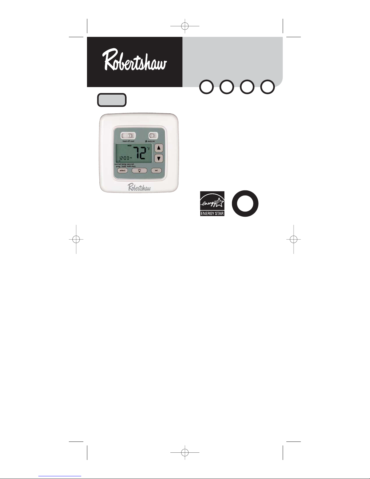
The Robertshaw C8601 is a single-stage thermostat designed to control
24 VAC gas or electric heating and cooling systems or single-stage
heat pump. The C8601 requires a common wire.
Features
• Large backlit display.
• Four preprogrammed E
NERGY STAR
®
setpoints for each day of
the week.
• Fahrenheit/Celsius display option.
• Programmable from 45°F (4°C) to 90°F (32°C).
• Accuracy within ± 1 degree.
• Adjustable temperature differential: 1-3 °F (1-1.5°C).
• Separate heating and cooling programs.
110-1103B
5 - 2 Day Programmable
1 Heat / 1 Cool
User’s Manual
Quick Start
Installation and
Programming
W
A
R
R
A
N
T
Y
2
T
W
O
Y
E
A
R
DIGITAL
PROGRAMMABLE
THERMOSTAT
C8601
ELECTRIC
E
GAS
G
OIL
O
®
NeW
HEAT PUMP
H
As an ENERGY STAR®partner, Invensys Controls Americas has determined
that this thermostat product meets the ENERGY STAR®guidelines for
energy efficiency.
110-1103B.qxd 3/14/05 2:31 PM Page 1
Page 2

WARNING:
•
Always turn off power at the main power source by unscrewing
fuse or switching circuit breaker to the off position before installing,
removing, cleaning, or servicing thermostat.
•
Read all of the information in this manual before installing or
programming this thermostat.
•
DO NOT CONNECT TO 120 VAC. This is a 24V AC low voltage thermostat. Do not install on voltages higher than 30V AC.
•
All wiring must conform to local and national building and electrical
codes and ordinances.
•
Do not short (jumper) across terminals on the gas valve or at the
system control to test installation. This will damage the thermostat
and void the warranty.
•
Do not connect ground to any terminal in this unit.
Recycling Thermostat
If this thermostat REPLACES a thermostat that contains mercury,
DO NOT discard the old thermostat in the regular trash. Mercury
is harmful to humans and the environment. For this reason, do
not open, break, or crush the mercury cell. If mercury leaks from
a damaged cell, DO NOT touch or handle mercury with bare
hands. Use protective, non-absorbent gloves to place mercury
into a sealable container. Fill the container with sand or another
absorbent material and seal the container completely.
Return the mercury or mercury products, in a sealed container, to
Invensys Controls Americas or a local recycling center for proper
disposal. If you have any questions, call Robertshaw technical
support at 1-800-445-8299.
Invensys Controls Americas
3505 Laird Road – Unit #14
Mississauga, Ontario L5L 5Y7
Attn: Mercury Recycling Center
Replacing Existing Thermostat
Wiring Table
Old Label New Label Description
M, W, Rh, Rc R 24VAC, hot side
R5, V or 5
C, X or B C 24VAC, common side
Y or Y6 Y1 Cooling control
H, W or 4 W1 Heating control
F or G G Fan control relay
O O Cool active reversing valve
B B Heat active reversing valve
NOTE: THIS THERMOSTAT REQUIRES A 24 VAC COMMON WIRE FOR PROPER OPERATION.
NOTE: ON SOME OLDER MODELS, THE C TERMINAL CAN BE EITHER THE COOLING CONTROL OR
THE COMMON SIDE OF THE TRANSFORMER. CHECK FURNACE WIRING DIAGRAM TO
VERIFY C TERMINAL. IF IT IS THE COMMON SIDE OF THE TRANSFORMER, CONNECT TO
THE C TERMINAL.
2
!
110-1103B.qxd 3/14/05 2:31 PM Page 2
Page 3
WARNING:
In heat pump applications, do not connect anything to the W1
terminal. When switched to HP mode, W1 is connected internally
to Y1 on the thermostat.
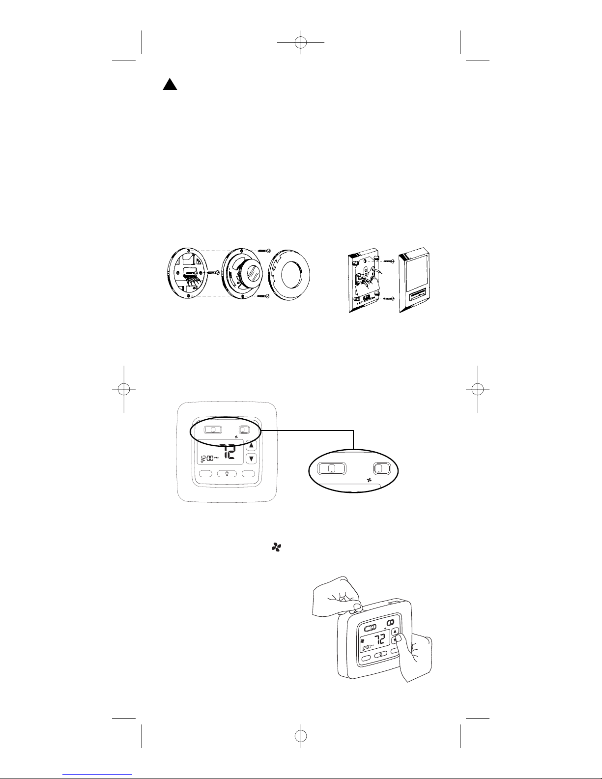
1. Turn off power to heating and cooling system.
2. Remove cover of old thermostat to expose wires. Do not
disconnect wires. (See Figure 1)
3. Label wires per the Wiring Table.
4. After labeling wires, remove wires from terminals.
5. Remove existing thermostat base from wall.
6. Refer to the following section for instructions on how to
install thermostat.
Figure 1
Installing Item C8601 Thermostat
NOTE: FOR NEW INSTALLATIONS, MOUNT THERMOSTAT ON AN INSIDE WALL, 4-5 FEET
ABOVE THE FLOOR
. DO NOT INSTALL BEHIND A DOOR, IN A CORNER, NEAR AIR VENTS,
IN DIRECT SUNLIGHT, OR NEAR ANY HEAT OR STEAM GENERATING FIXTURES. INSTALLATION
AT THESE PLACES WILL AFFECT THERMOSTAT OPERATION
.
1. Turn power off to the heating and cooling systems.
2. Place HEAT-OFF-COOL in OFF position.
3. Place AUTO–ON switch
into AUTO position.
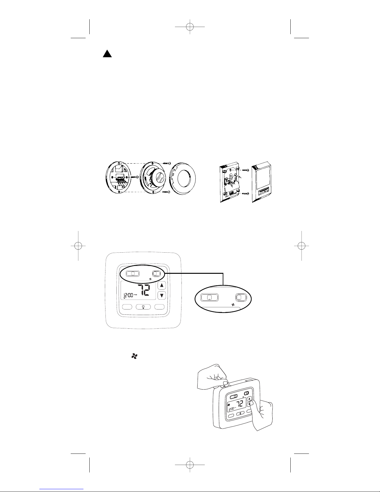
4. Remove the cover using a coin
or screwdriver (see Figure 2).
5. Place thermostat against the
wall at desired location. Make
sure wires will feed through
opening on base of thermostat.
3
h
e
a
t o
ff c
o
o
l
h
o
ld
v
a
c
p
r
o
g
r
u
n
/s
e
t
h
o
ld
te
m
p
c
lo
c
k
s
e
t
a
u
to
o
n
M
O
N
°
F
select
set
heat off cool
auto on
Figure 2
!
110-1103B.qxd 3/14/05 2:31 PM Page 3
heat off cool
MON
temp
run/set
hold
prog
select
auto on
°
F
set
vac
clock
hold
set
Page 4
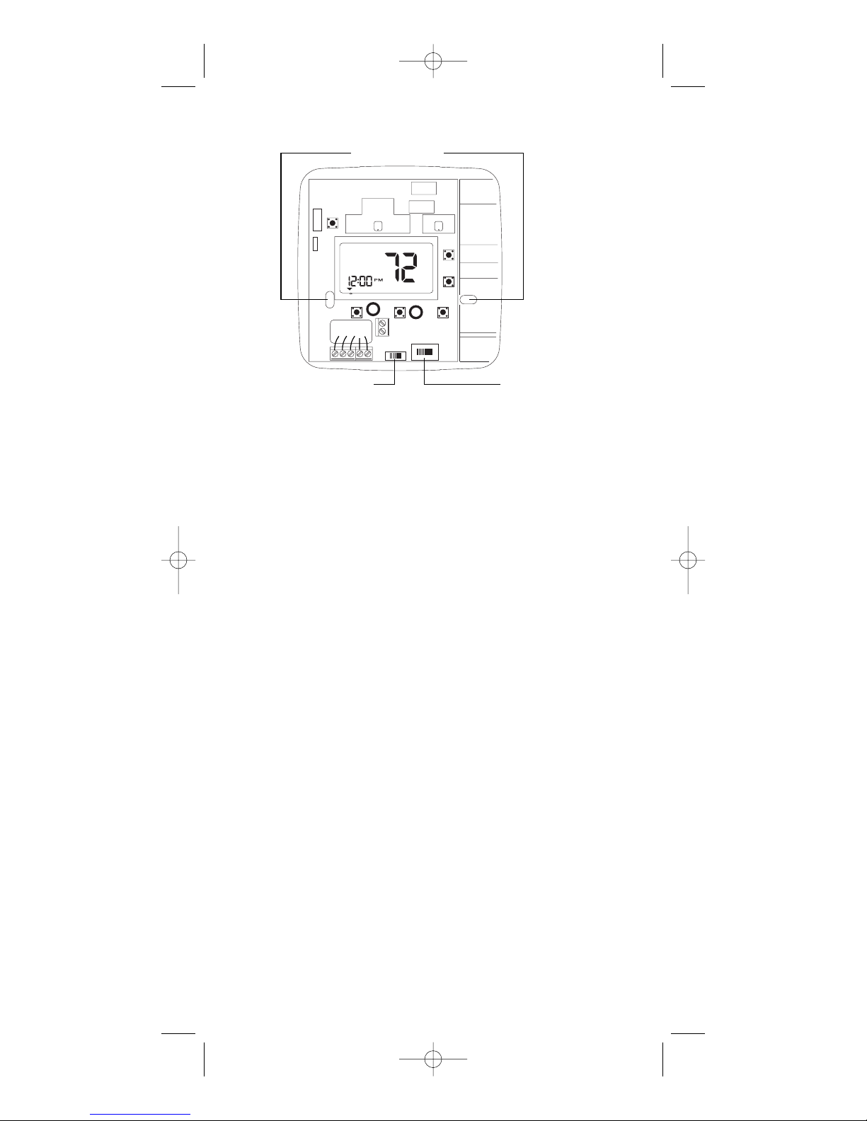
6. Mark placement of mounting holes (see Figure 3). Set base aside.
7. Drill the marked holes using a 3/16” (5mm) drill bit. NOTE: Enclosed
plastic anchors do not require a drilled hole for drywall.
8. Tap plastic anchors into the wall.
9. Align base with plastic anchors and feed wires through opening
(see Figure 3).
10. Secure base to wall with supplied screws.
11. Connect wires to terminal strip. Refer to wiring diagrams on page 5.
Make sure wire connections are secure.
12. Place Electric/Gas switch into either the ELEC or GAS position
depending on the type of furnace (see Figure 3).
13. Place the HP option switch into either the NON_HP or HP position
depending on the type of system you are using (see Figure 3). Use
the HP position for heat pumps ONLY. Use the NON_HP setting for
everything else.
14. Replace cover on thermostat by snapping into place.
15. Turn on power to system. Test thermostat as described in the
section To Test Thermostat.
4
Mounting Holes
ELECTRIC/GAS SWITCH
Selects fan control.
HP OPTION SWITCH
Heat pump switch.
Figure 3
110-1103B.qxd 3/14/05 2:31 PM Page 4
MON
C
R
GOB Y1W1
°
F
Page 5
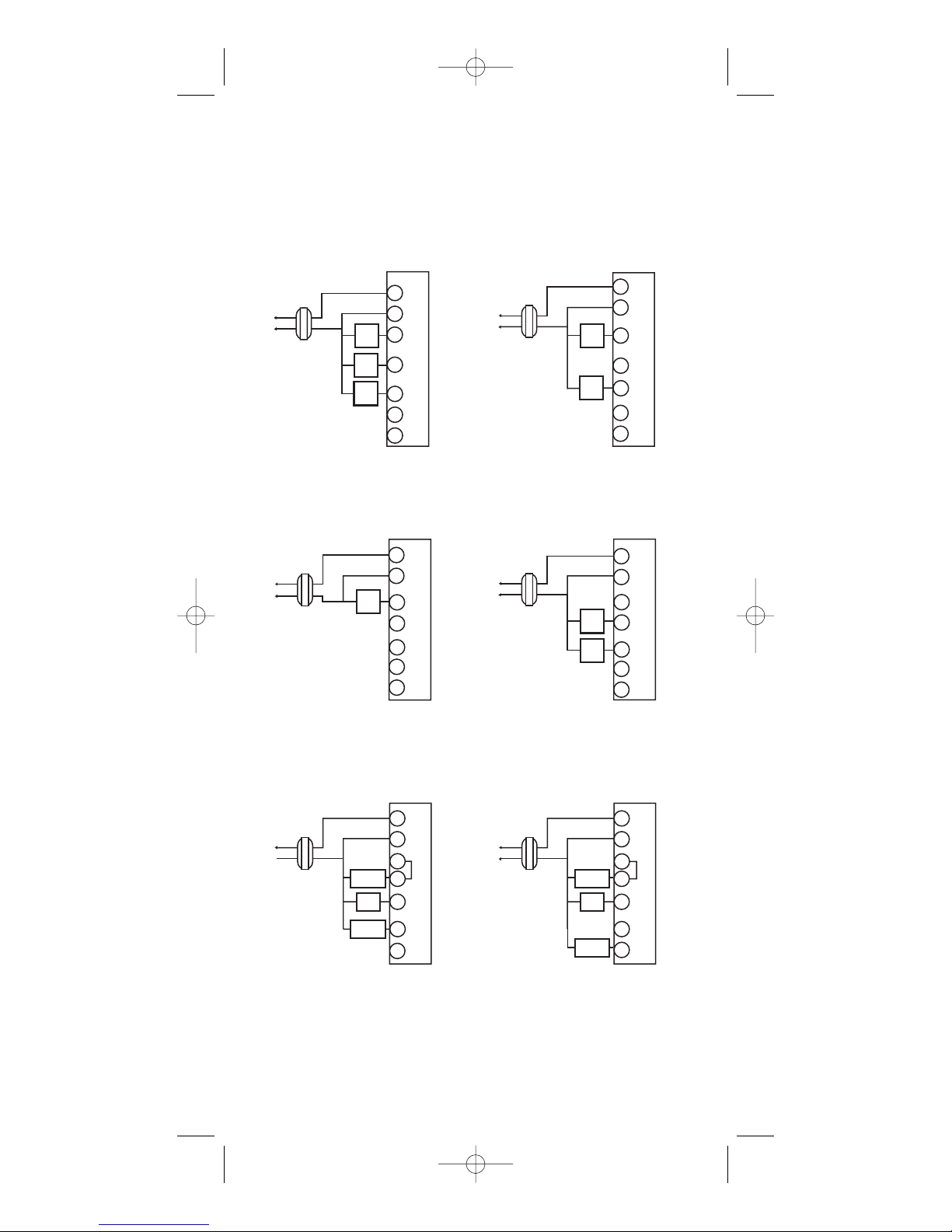
Wiring Diagrams
The following is just a sample of the most common types of HVAC
systems. Refer to your system’s installation manual for wiring information.
5
110-1103B.qxd 3/14/05 2:31 PM Page 5
HEAT/COOL
4-WIRE
SINGLE TRANSFORMER
R
T
H
C
E
R
W1
M
O
Y1
S
T
G
A
T
O
B
120 VAC
Transformer
Hot
24 VAC
Heating
Control
Cooling
Control
Fan
Control
HEAT ONLY
2-WIRE
SINGLE TRANSFORMER
120 VAC
Transformer
Hot
24 VAC
Heating
Control
R
T
C
H
E
W1
R
Y1
M
O
G
S
T
O
A
T
B
HEAT ONLY
3-WIRE
SINGLE TRANSFORMER
120 VAC
Transformer
Hot
24 VAC
Heating
Control
Fan
Control
R
C
W1
Y1
G
O
B
COOL ONLY
3-WIRE
SINGLE TRANSFORMER
Cooling
Control
Fan
Control
R
C
W1
Y1
G
O
B
120 VAC
Transformer
Hot
24 VAC
T
H
E
R
M
O
S
T
A
T
T
H
E
R
M
O
S
T
A
T
HEAT PUMP WITH
COOL ACTIVE
REVERSING VALVE
Transformer
Hot
120 VAC
24 VAC
Compressor
Contactor
Fan
Relay
Reversing
Valve
NOTE: Make sure the HP switch is in the HP position.
When switched to HP mode,
W1 is connected internally to Y1.
HEAT PUMP WITH
HEAT ACTIVE
REVERSING VALVE
R
T
C
H
E
W1
R
M
Y1
O
G
S
120 VAC
Transformer
Hot
24 VAC
T
A
O
T
B
NOTE: Make sure the HP switch is in the HP position.
When switched to HP mode,
W1 is connected internally to Y1.
Compressor
Contactor
Fan
Relay
Reversing
Valve
R
T
C
H
E
W1
R
M
Y1
O
G
S
T
A
O
T
B
Page 6
6
To Test Thermostat
WARNING: DO NOT SHORT (JUMPER) ACROSS TERMINALS OF GAS
VALVE OR SYSTEM CONTROL TO TEST OPERATION. THIS WILL
DAMAGE THE THERMOSTAT AND VOID YOUR WARRANTY.
CAUTION: DO NOT SWITCH SYSTEM TO COOL OR LEAVE IN COOL MODE
IF THE TEMPERATURE IS BELOW 50°F (10°C). THIS CAN
DAMAGE THE AIR CONDITIONING SYSTEM AND CAUSE PERSONAL INJURY.
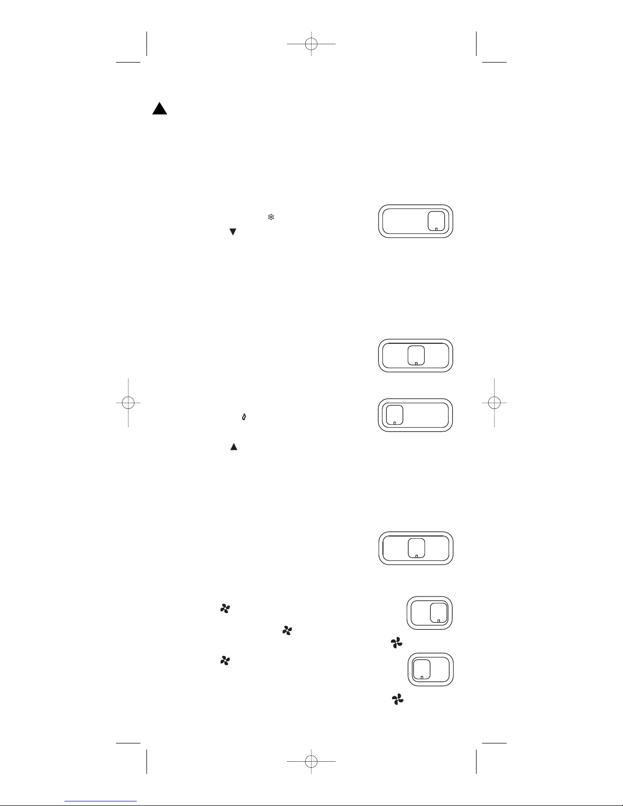
1. Place the HEAT-OFF-COOL switch into the
COOL position. The will be displayed.
2. Press the button until the temperature
setting is at least 3 degrees below the room
temperature. The air conditioning system
should turn on within a few seconds.
NOTE: ONCE THE THERMOSTAT TURNS OFF WHEN IN THE COOL MODE,
A BUILT IN 5-MINUTE DELAY PREVENTS THE SYSTEM FROM
TURNING ON AGAIN. THIS PROTECTS THE COMPRESSOR. NO
ADDITIONAL TIME DELAY RELAY IS REQUIRED. TO OVERRIDE THE
5-MINUTE DELAY FOR INSTALLATION, PRESS THE RESET BUTTON.
3. Put the HEAT-OFF-COOL switch into the OFF
position. The air conditioning system should
turn off.
4. Put the HEAT-OFF-COOL switch into the HEAT
position. The will be displayed.
5. Press the button until the temperature
setting is at least 3 degrees above room
temperature. The heating system should turn on. The fan may
not turn on immediately, depending on the fan delay built into
the furnace.
NOTE: If HP is selected, the heat will not come on until the 5 minute
short cycle protection has expired.
6. Put the HEAT-OFF-COOL switch into the OFF
position. The heating system should turn off.
The fan may continue to run for a short
period of time.
7. Put the AUTO-ON switch into the ON
position. The blower fan should turn on.
The display will show a .
8. Put the AUTO-ON switch into the AUTO
position. The blower fan should turn off.
heat off cool
heat off cool
heat off cool
heat off cool
auto on
auto on
!
110-1103B.qxd 3/14/05 2:31 PM Page 6
Page 7
Programming Guide
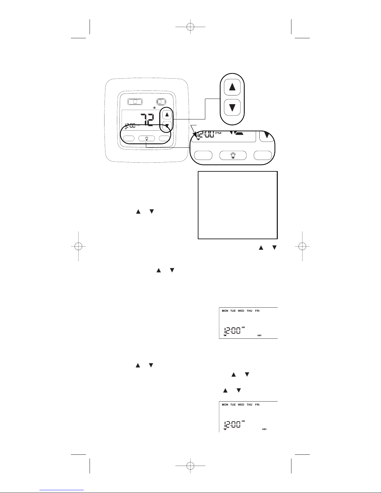
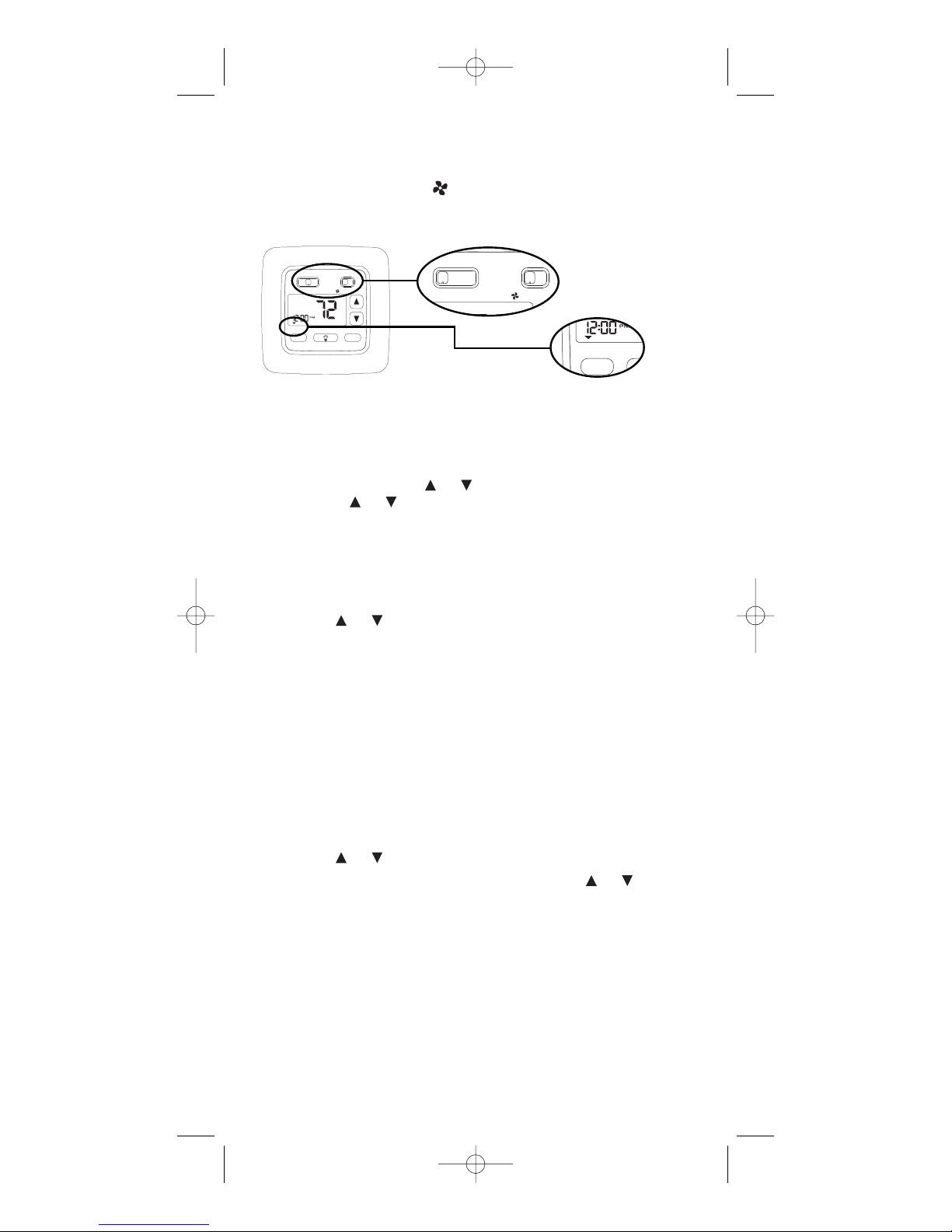
SETTING TIME OF DAY AND
DAY OF WEEK
1. Press SELECT until the cursor is
over SET CLOCK. Press SET. The
HOURS segment will be blinking.
Use the or button to adjust
the time. NOTE: The AM or PM
indicator will change as the
HOURS display rolls through a 24
hour cycle.
2. Press SET. The MINUTES segment will be blinking. Use the or
button to adjust the MINUTES setting.
3. Press SET. The DAY segment will be blinking at the top of the
display. Use the or button to adjust the day of the week.
Press SET.
PROGRAMMING YOUR THERMOSTAT
The C8601 thermostat features 1-button programming. Simply follow
these steps to customize your thermostat for your lifestyle.
1. Place the HEAT-OFF-COOL switch into the
HEAT position. Make sure the cursor is in
the RUN/SET PROG position. Press SET.
The HOURS segment will be blinking.
MON thru FRI (the work week) will be displayed across the top. AM1 will be illuminated in the lower right
hand corner. You can now start programming the first event of the
work week.
2. Use the or button to adjust the hour of the first event. Press SET.
3. The MINUTES segment will be blinking. Use the or button to
adjust the minutes. Press SET.
4. The temperature should be blinking. Use the or button to
adjust the desired temperature of the first event. Press SET.
5. AM2 should now be displayed. Repeat
steps 2-4 to program the remaining events
(PM1 and PM2) for the work week. There
are a total of 4 events.
7
MON = MONDAY
TUE = TUESDAY
WED = WEDNESDAY
THU = THURSDAY
FRI = FRIDAY
SAT = SATURDAY
SUN = SUNDAY
select
set
hold
vac
prog
run/set
hold
temp
clock
set
Cursor
110-1103B.qxd 3/14/05 2:31 PM Page 7
heat off cool
MON
set
temp
vac
run/set
prog
select
clock
hold
hold
auto on
°
F
set
Page 8

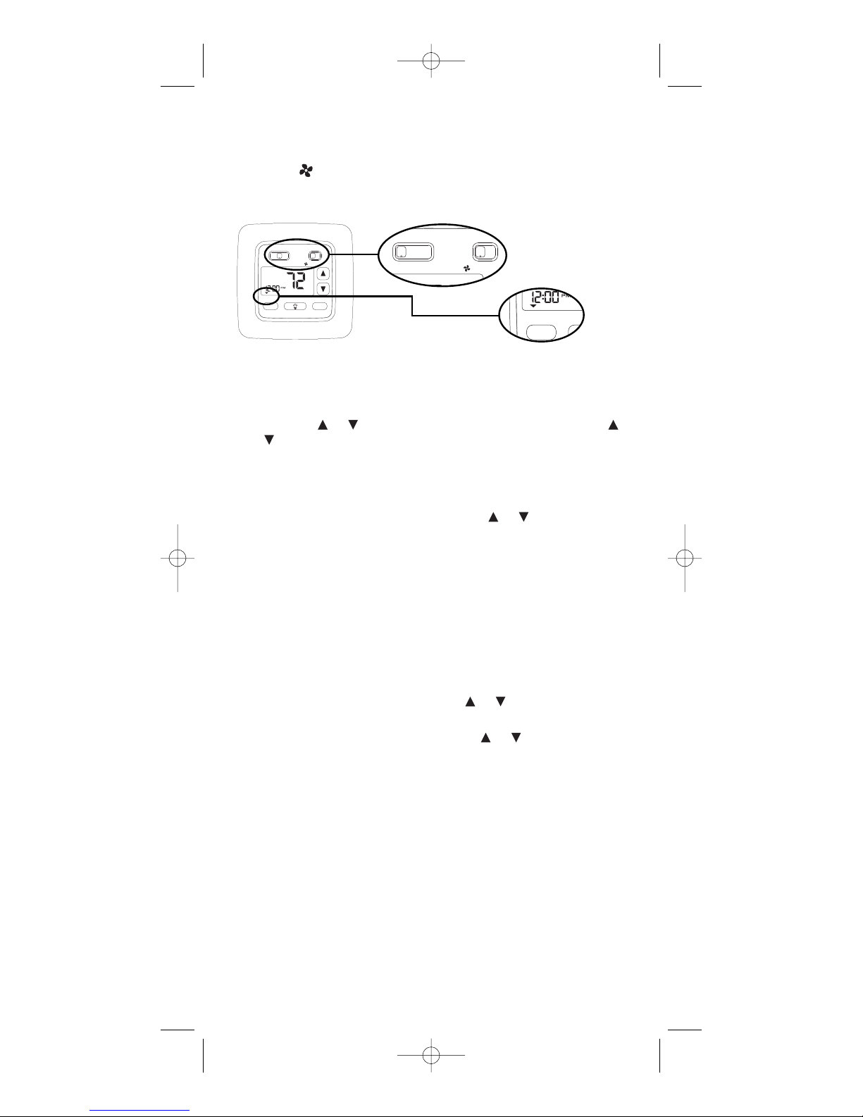
6. After pressing SET for the 4th event, the
day of the week along the top will switch
to SAT SUN and AM1 will be displayed.
Repeat steps 2-4 to program the
weekend settings.
7. With the weekend settings programmed, place the HEAT-OFF-COOL
switch in the COOL position. Repeat steps 2-6 to program the
cooling settings.
CUSTOMIZING YOUR THERMOSTAT
Settings
System
Cool: The thermostat controls the cooling.
Off: The heating and cooling systems are off.
Heat: The thermostat controls the heat.
Fan
Auto: Equipment controls the fan.
On: The fan operates continuously.
Temperature Differential
The temperature differential is factory set at 1.0°F (.5°C). This means that
whenever the room temperature changes by one degree Fahrenheit
from the temperature setting, the system will turn on. If the system turns
on too often, increase the temperature differential.
Changing Fahrenheit (°F) to Celsius (°C), Clock Setting, Temperature
Differential, and Filter Monitor
You can change temperature scales (F or C), set a 12 or 24 hour clock,
adjust differentials and change the filter monitor setting by following
these instructions.
1. Press SELECT and SET at the same time.
Hold for 3 seconds. An F should be
blinking in the display. Use the or
button to toggle between Farhenheit (F)
or Celsius (C).
2. Press SET. CLOC will be displayed in the
lower left corner. Use the or
button to toggle between 12 or 24 for the
clock setting.
3. Press SET. diFF will be displayed in the
lower left corner. Use the or
button to adjust the 1st stage differential
between 1°F and 3°F (1°C and 1.5°C).
4. Press SET. CHECK FILTER will be
displayed and the length of the filter setting will be blinking in the lower left corner. Use the or button to adjust the
filter setting from 0 (OFF) to 9900 hours.
NOTE: The filter timer is based on
equipment run time. Select the length of time based on your filter's
recommended service interval.
5. Press SET or wait 5 seconds and the thermostat will return to the
normal operating mode.
8
110-1103B.qxd 3/14/05 2:31 PM Page 8
Page 9
Begin Programmed Operation
1. Make sure the cursor is above RUN/SET PROG.
2. Place AUTO–ON switch into AUTO.
3. Place HEAT-OFF-COOL switch into COOL or HEAT depending on
the season.
Temporary Program Hold
You can temporarily increase or decrease the temperature and hold it for
3 hours or until the next program event, whichever comes first.
1. Press the or button. The temperature will blink. Using the
or button, adjust the temperature to the desired level.
2. Press SET.
Another way to select a temporary hold is:
1. Press SELECT until the cursor is over TEMP HOLD. Press SET.
The temperature will be blinking. Use the or button to change
the temperature.
2. Press SET.
To cancel a temporary hold, press SELECT until the cursor is above
RUN/SET PROG. Press SET.
Vacation Hold
You can set your thermostat to hold a desired temperature for 1-365 days.
Vacation hold terminates at midnight of the last day. The thermostat
returns to normal operation the next day at 12:01 AM.
1. Press SELECT until the cursor is over VAC HOLD. Press SET. The
temperature will be blinking. Use the or button to change the
temperature.
2. Press SET. 7d will be displayed. Use the or button to adjust
between 1 and 365 days.
3. Press SET.
To cancel a vacation hold, press SELECT until the cursor is above
RUN/SET PROG. Press SET.
9
heat off cool
auto on
select
hold
vac
prog
run/set
hold
temp
clo
s
110-1103B.qxd 3/14/05 2:31 PM Page 9
heat off cool
MON
run/set
prog
select
auto on
°
F
set
temp
vac
clock
hold
hold
set
Page 10

Check Filter Reset
Once the filter timer has expired,
CHECK FILTER will turn on and stay
on. To clear the message and reset
the timer:
1. Press SELECT and SET and hold
for 3 seconds. CLr will appear in
the time display.
2. Press any key to clear the message.
The display will transition to the temperature scale display. See step 4 in
CUSTOMIZING YOUR THERMOSTAT.
3. No further input is needed. Within a few seconds, the display will
return to the normal operating mode.
Backlit Display
This thermostat is equipped with a backlight to make night time temperature adjustments quick and easy. Press the button to activate the
backlight. The backlight will turn off after about 10 seconds of inactivity.
Reset
The RESET button is located above the upper left corner of the display.
Only use the reset feature if the thermostat is malfunctioning.
10
RESET
BUTTON
110-1103B.qxd 3/14/05 2:31 PM Page 10
MON
GOBY1W1
°
F
C
R
Page 11
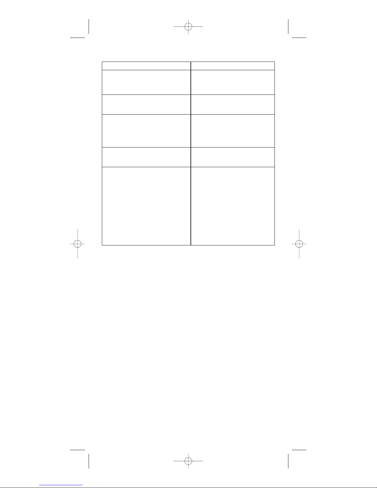
Troubleshooting
Symptom Remedy
Thermostat does not turn Check wiring.
on system. (See Installing Item C8601
Thermostat.)
Thermostat turns on and off too Increase temperature differential.
frequently. (See Programming Guide.)
System fan does not operate Move the Electric/Gas switch to
properly. either gas or electric, to match
system. (See Installing Item
C8601 Thermostat.)
Time shown on display is not the Change time of day setting.
current time of day. (See Programming Guide.)
Thermostat does not Thermostat may not have been
follow program. programmed in HEAT or COOL
position. Verify program.
Check AM/PM indicators at time
of day and programmed time
changes.
(See Programming Guide.)
Verify program and day of week
are correct.
(See Programming Guide.)
If problems with thermostat cannot be resolved, call:
Technical Support: (800) 445-8299
Monday-Friday 7:30-5:30 CST
For after hours service, a 24-hour
automated help line is available.
11
110-1103B.qxd 3/14/05 2:31 PM Page 11
Page 12

12
©2005 Invensys Controls Americas 110-1103B
Controls Americas
191 E. North Avenue
Carol Stream, Illinois 60188
United States of America
Two-Year Limited Warranty
Invensys Controls Americas warrants to the original contractor
installer or to the original consumer user, each new Robertshaw thermostat to be free from defects in materials and workmanship under normal
use and service for a period of two (2) years from date of purchase. This
warranty and our liability does not apply to batteries or merchandise that
has been damaged by misuse, neglect, mishandling, alterations, improper
installation, or use in a way other than in accordance with Invensys
Controls Americas recommendations and instructions.
Invensys Controls Americas agrees to repair or replace at its option any
thermostat under warranty provided it is returned within the warranty
period, postage prepaid, with proof of the date of purchase. Cost of thermostat removal or reinstallation is not the responsibility of Invensys
Controls Americas.
Repair or replacement as provided under this warranty is the exclusive
remedy of the consumer. Invensys Controls Americas shall not be liable
for any incidental or consequential damages for breach of any express or
implied warranty on this product, or under any other theory of liability.
Except to the extent prohibited by applicable law, any implied warranty of
merchantability or fitness for a particular purpose on this product is limited to the duration of this warranty.
Some states do not allow the exclusion or limitation of incidental or consequential damages, or allow limitations on how long an implied warranty
lasts, so the above limitations or exclusions may not apply to you. This
warranty gives you specific legal rights, and you may also have other
rights which vary from state to state.
For warranty returns, send thermostat, shipping prepaid to:
Invensys Controls Americas
3505 Laird Road – Unit #14
Mississauga, Ontario L5L 5Y7
Attn: Warranty Department
110-1103B.qxd 3/14/05 2:31 PM Page 12
Page 13

13
Application
Le Robertshaw C8601 est un thermostat à étage unique conçu pour
contrôler les systèmes de chauffage et de climatisation de 24 V c.a. à
gaz ou à électricité ou les thermopompes à étage unique. Le C8601
nécessite un câble neutre.
Caractéristiques
• Grand affichage rétroéclairé.
• Quatre points de consigne ENERGY STAR
®
pré-programmés pour
chaque jour de la semaine.
• Option d’affichage en degrés Fahrenheit ou Celsius.
• Programmable de 45 °F (4 °C) à 90 °F (32 °C).
• Précision : ± 1 degré.
• Différentiel de température ajustable : 1 à 3 °F (1 à 1,5 °C).
• Programmes distincts de chauffage et de climatisation.
110-1103B
Programmation 5 / 2 jours
1 Chauffage /
1 Climatisation
Notice
d’utilisation
Installation et
programmation
rapides
THERMOSTAT
NUMÉRIQUE
PROGRAMMABLE
c8601
ÉLECTRIQUE
E
GAZ
G
HUILE
H
®
THERMOPOMPE
T
NOUVEAU
D
E
2
A
N
S
G
A
R
A
N
T
I
E
En tant que partenaire d’ENERGY STAR®Invensys Controls Americas a
conclu que ce thermostat est conforme aux lignes directrices d’ENERGY
STAR®concernant l’efficacité énergétique.
110-1103B.qxd 3/14/05 2:31 PM Page 13
Page 14

AVERTISSEMENT :
•
Toujours couper le courant au panneau principal en dévissant le
fusible ou en mettant le disjoncteur en position d’arrêt (OFF) avant
d’installer, d’enlever, de nettoyer ou de réparer le thermostat.
• Lire attentivement tous les renseignements contenus dans la
présente notice avant d’installer ou de programmer le thermostat.
• NE PAS CONNECTER À DU 120 V c.a. Ce thermostat utilise un
courant basse tension 24 V c.a. Ne pas le soumettre à une tension
supérieure à 30 V c.a.
• L’ensemble du câblage doit être conforme aux codes fédéraux,
provinciaux et locaux du bâtiment et de l’électricité.
• Ne pas court-circuiter (avec un cavalier) les bornes du robinet de
gaz ou des commandes du système pour tester l’installation. Cela
endommagerait le thermostat et annulerait la garantie.
• Ne connecter aucune borne de cette unité à la masse.
Recyclage du thermostat
Si ce thermostat REMPLACE un thermostat contenant du mercure, NE
PAS JETER l’ancien thermostat à la poubelle. Le mercure est toxique pour
les humains et l’environnement. C’est pour cette raison qu’il ne faut pas
ouvrir, briser, ou éclater la cellule de mercure. Si du mercure s’échappe
de la cellule endommagée, NE PAS toucher ou manipuler le mercure à
mains nues. Utiliser des gants de protection non absorbants pour placer
le mercure dans un conteneur scellable. Remplir le conteneur de sable ou
de tout autre matière absorbante et sceller complètement le conteneur.
Retourner le mercure ou les produits du mercure dans un conteneur scellé à Invensys Controls Americas ou à un centre de recyclage proche pour
s’en débarrasser de façon adéquate. Pour toutes questions, appeler le
soutien technique de Robertshaw au 1-800-445-8299. Nos représentants
techniques sont situés aux Etats-Unis et le service est disponible uniquement en anglais pour le moment.
Invensys Controls Americas
3505 Laird Road – Unit #14
Mississauga, Ontario L5L 5Y7
Attn: Mercury Recycling Center
Remplacement du thermostat
Tableau des câblages
Ancien code Nouveau code Description
M, W, Rh, Rc R 24 V c.a., côté sous tension
R5, V ou 5
C, X ou B C 24 V c.a., côté neutre
Y ou Y6 Y1 Commande de la climatisation
H, W ou 4 W1 Commande du chauffage
F ou G G Relais de commande du ventilateur
O O Robinet inverseur en mode de climatisation
B B Robinet inverseur en mode de chauffage
REMARQUE : CE THERMOSTAT NÉCESSITE UN CÂBLE NEUTRE DE 24 V C.A. POUR BIEN
FONCTIONNER.
REMARQUE : SUR QUELQUES ANCIENS MODÈLES, LA BORNE C PEUT CORRESPONDRE SOIT À
LA COMMANDE DE LA CLIMATISATION, SOIT AU CÔTÉ NEUTRE DU TRANSFORMATEUR.
VÉRIFIER LE SCHÉMA DE CÂBLAGE DE L’APPAREIL DE CHAUFFAGE POUR IDENTIFIER LA BORNE
C. S’IL S’AGIT DU CÔTÉ NEUTRE DU TRANSFORMATEUR, DÉBRANCHER LE À LA BORNE C.
14
!
110-1103B.qxd 3/14/05 2:31 PM Page 14
Page 15
AVERTISSEMENT :
Dans les applications de thermopompes ne rien brancher à la borne
W1. Lorsque le thermostat est en mode HP, la borne W1 se branche au
thermostat à l’interne à la borne Y1.
1. Couper le courant qui alimente les systèmes de chauffage et de
climatisation.
2. Retirer le couvercle de l’ancien thermostat, pour exposer les fils.
Ne pas débrancher les fils (Fig. 1).
3. Identifier les fils selon les indications du tableau des câblages.
4. Après avoir identifié les fils, les débrancher des bornes.
5. Retirer du mur la base de l’ancien thermostat.
6. Se reporter à la section suivante pour l’installation du nouveau
thermostat.
Installation du thermostat, modèle C8601
REMARQUE : S’IL S’AGIT D’UNE NOUVELLE INSTALLATION, MONTER LE THERMOSTAT SUR UN MUR INTÉRIEUR, À 4-5 PIEDS DU SOL. NE PAS L’INSTALLER
DERRIÈRE UNE PORTE, DANS UNE ENCOIGNURE, PRÈS DE BOUCHES D’AÉRATION,
DANS UN ENDROIT EXPOSÉ À LA LUMIÈRE DIRECTE DU SOLEIL, NI PRÈS D’APPAREILS PRODUISANT DE LA CHALEUR OU DE LA VAPEUR. LE FONCTIONNEMENT
DU THERMOSTAT EN SERAIT AFFECTÉ.
1. Couper le courant qui alimente les systèmes de chauffage et de
climatisation.
2. Placer le commutateur HEAT-COOL-OFF sur OFF (arrêt).
3. Placer le commutateur AUTO-ON sur AUTO (automatique).
4. Retirer le couvercle à l’aide
d’une pièce de monnaie ou
d’un tournevis (Fig. 2)
5. Placer le thermostat contre le
mur, à l’endroit désiré. Vérifier
que les fils passent par l’ouverture prévue dans la base.
15
h
e
a
t o
ff c
o
o
l
h
o
ld
v
a
c
p
r
o
g
r
u
n
/s
e
t
h
o
ld
te
m
p
c
lo
c
k
s
e
t
a
u
to
o
n
M
O
N
°
F
select
set
heat off cool
auto on
Figure 2
!
Figure 1
110-1103B.qxd 3/14/05 2:31 PM Page 15
run/set
MON
prog
select
heat off cool
temp
vac
hold
hold
auto on
°
F
set
clock
set
Page 16

6. Marquer l’emplacement des trous de fixation (Fig. 3). Mettre la base
de côté.
7. À l’aide d’une mèche de 3/16 po (5 mm), percer des trous aux
emplacements marqués pour le montage. REMARQUE : Les chevilles
d’ancrage en plastique fournies ne nécessitent pas le perçage de
trous, dans le cas d’une installation sur cloison sèche.
8. Enfoncer les chevilles en plastique dans les trous de fixation.
9. Aligner la base du thermostat sur les chevilles et faire passer les fils
par l’ouverture prévue à cet effet (Fig. 3).
10. Fixer la base du thermostat au mur à l’aide des vis fournies.
11. Brancher les fils aux bornes correspondantes. Se reporter aux
schémas de câblage à la page 17. S’assurer que les branchements
tiennent bien.
12. Placer le commutateur ELEC/GAS soit sur ELEC (électrique), soit sur
GAS (gaz), en fonction du type d’appareil de chauffage (Fig. 3).
13. Placer le commutateur d’option HP sur NON_HP ou HP selon le type
de système que vous utilisez (voir la Figure 3). Utiliser la position HP
pour les thermopompes uniquement. Utiliser le réglage NON_HP
pour toute autre chose.
14. Remettre le couvercle sur le thermostat en l’emboîtant.
15. Rétablir le courant. Vérifier le fonctionnement du thermostat en suivant la procédure décrite plus loin, sous Test de fonctionnement du
thermostat.
16
trous de fixation
COMMUTATEUR
ÉLECTRIQUE/GAZ
Sélectionne la commande
du ventilateur.
COMMUTATEUR D’OPTION HP
Commutateur de la thermopompe
Figure 3
110-1103B.qxd 3/14/05 2:31 PM Page 16
MON
GOB Y1W1
C
R
°
F
Page 17

Diagrammes de câblage
Les diagrammes ci-dessous représentent un échantillon des systèmes
CVC les plus courants. Consulter le manuel d’installation de votre système
pour les renseignements relatifs au câblage.
17
110-1103B.qxd 3/14/05 2:31 PM Page 17
TRANSFORMATEUR SIMPLE À
4 FILS AVEC
CHAUFFAGE/CLIMATISATION
R
Transformateur
Conducteur
120 V c.a.
24 V c.a.
Commande
de chauffage
Commande
de climatisation
Commande
de ventilation
T
H
C
E
R
W1
M
O
Y1
S
T
G
A
T
O
B
TRANSFORMATEUR SIMPLE
À 2 FILS AVEC
CHAUFFAGE SEULEMENT
Commande
de chauffage
R
T
C
H
E
W1
R
Y1
M
O
G
S
T
O
A
T
B
Transformateur
Conducteur
120 V c.a.
24 V c.a.
TRANSFORMATEUR SIMPLE
À 3 FILS AVEC
CHAUFFAGE SEULEMENT
R
Transformateur
Conducteur
120 V c.a.
24 V c.a.
Commande
de chauffage
Commande
de ventilation
T
C
H
E
R
W1
M
O
Y1
S
T
G
A
T
O
B
TRANSFORMATEUR SIMPLE
À 3 FILS AVEC
CLIMATISATION SEULEMENT
Commande
de climatisation
Commande
de ventilation
R
T
C
H
E
W1
R
Y1
M
O
S
G
T
O
A
T
B
Transformateur
Conducteur
120 V c.a.
24 V c.a.
THERMOPOMPE AVEC
ROBINET INVERSEUR
EN MODE CLIMATISATION
Transformateur
Conducteur
120 V c.a.
24 V c.a.
REMARQUE : S’assure que le commutateur HP
est à la position HP. Lorsque mis en mode HP,
W1 est branché à l’interne à Y1.
Compressor
Contactor
Commande
de ventilation
Robinet
inverseur
THERMOPOMPE AVEC
ROBINET INVERSEUR
EN MODE CHAUFFAGE
R
T
C
H
E
W1
R
M
Y1
O
G
S
T
A
O
T
B
Transformateur
Conducteur
120 V c.a.
24 V c.a.
REMARQUE : S’assure que le commutateur HP
est à la position HP. Lorsque mis en mode HP,
W1 est branché à l’interne à Y1.
Compressor
Contactor
Commande
de ventilation
Robinet
inverseur
R
T
C
H
E
W1
R
M
Y1
O
G
S
T
A
O
T
B
Page 18

18
Test de fonctionnement du thermostat
AVERTISSEMENT : NE PAS COURT-CIRCUITER (AVEC UN CAVALIER) LES
BORNES DU ROBINET DE GAZ OU DES COMMANDES DU SYSTÈME POUR
VÉRIFIER LE FONCTIONNEMENT. CELA ENDOMMAGERAIT LE THERMOSTAT ET
ANNULERAIT LA GARANTIE.
MISE EN GARDE : NE PAS FAIRE PASSER LE SYSTÈME EN MODE CLIMATISATION (COOL) OU PARTIR DANS LE MODE CLIMATISATION SI LA TEMPÉRATURE
EST AU-DESSOUS DE 50 ºF (10 ºC). CELA POURRAIT ENDOMMAGER LE
SYSTÈME DE CLIMATISATION OU CAUSER DES BLESSURES CORPORELLES.
1. Placer le commutateur HEAT-OFF-COOL sur
COOL (climatisation). Le s’affichera.
2. Appuyer sur jusqu’à ce que la température
sélectionnée se situe au moins à 1,5 degrés
au-dessous de la température ambiante. Le
système de climatisation devrait se mettre en marche au bout de
quelques secondes.
REMARQUE : EN MODE CLIMATISATION, LORSQUE LE THERMOSTAT COMMANDE L’ARRÊT DU SYSTÈME, UN TEMPORISATEUR INTÉGRÉ EMPÊCHE LE
COMPRESSEUR DE SE REMETTRE EN MARCHE PENDANT 5 MINUTES ENVIRON. CELA VISE À PROTÉGER LE COMPRESSEUR. AUCUN AUTRE RELAIS DE
TEMPORISATION N’EST REQUIS. POUR DÉRIVER LE TEMPORISATEUR DE 5
MINUTES LORS DE L’INSTALLATION, APPUYER SUR LE BOUTON DE
RÉINITIALISATION.
3. Placer le commutateur HEAT-OFF-COOL sur
OFF (arrêt). Le système de climatisation
devrait s’arrêter.
4. Placer le commutateur HEAT-OFF-COOL sur
HEAT (chauffage). Le s’affichera.
5. Appuyer sur jusqu’à ce que la température sélectionnée se situe au moins à 1,5 degrés au-dessus de la
température ambiante. Le système de chauffage devrait se mettre
en marche. Le ventilateur peut ne pas se mettre en marche immédiatement, si la chaudière est équipée d’un temporisateur intégré.
REMARQUE : Lorsque HP est choisi, le chauffage se mettra en marche
uniquement après l’expiration de la protection de court-circuit de 5 minutes.
6. Placer le commutateur HEAT-OFF-COOL sur
OFF (arrêt). Le système de chauffage devrait
s’arrêter. Là encore, il se peut que le ventilateur ne s’arrête qu’au bout d’un certain délai.
7. Placer le commutateur AUTO-ON sur ON
(marche). Le ventilateur devrait se mettre en
marche. Un devrait s’afficher.
8. Placer le commutateur AUTO-ON sur
AUTO (automatique). Le ventilateur devrait
s’arrêter.
heat off cool
heat off cool
heat off cool
heat off cool
auto on
auto on
!
110-1103B.qxd 3/14/05 2:31 PM Page 18
Page 19

Guide de programmation
RÉGLAGE DE L’HEURE ET DU JOUR
1. Appuyer sur SELECT jusqu’à ce que le
curseur se trouve au-dessus du bouton
SET CLOCK. Appuyer sur le bouton SET.
La partie HEURES clignotera. Utiliser le
bouton ou pour régler l’heure.
REMARQUE : L’indicateur AM ou PM
change au fur et à mesure que l’affichage HEURE défile sur un cycle de 24
heures.
2. Appuyer sur SET. La partie MINUTES clignotera. Utiliser le bouton
ou pour régler les MINUTES.
3. Appuyer sur le bouton SET. La partie JOUR clignotera sur la partie
supérieure de l’affichage. Utiliser le bouton ou pour régler le
jour. Appuyer sur SET.
PROGRAMMATION DU THERMOSTAT
Le thermostat C8601 ne possède qu’un bouton pour la programmation.
Suivre tout simplement les étapes suivantes pour programmer votre thermostat selon votre style de vie.
1. Placer le commutateur HEAT-OFF-COOL
sur COOL (climatisation). Vérifier que le
curseur se trouve à la position RUN/SET
PROG. Appuyer sur SET. La partie
HEURES clignotera. Les cinq jours de la
semaine (lundi à vendredi) s’afficheront en haut de l’écran. En bas à
droite, AM1 s’illuminera. Vous pouvez commencer la programmation
du premier événement de la semaine de cinq jours.
2. Utiliser le bouton ou pour régler l’heure du premier événement.
Appuyer sur SET.
3. La partie MINUTES clignotera. Utiliser le bouton ou pour
régler les minutes. Appuyer sur SET.
4. La température devrait clignoter. Utiliser le bouton ou pour régler
à la température voulue du premier événement. Appuyer sur SET.
5. AM2 devrait s’afficher. Répéter les étapes
2 à 4 pour programmer les événements
suivants (PM1 et PM2) pour la semaine
de cinq jours. Cela représente un total de
quatre événements.
19
MON = LUNDI
TUE = MARDI
WED = MERCREDI
THU = JEUDI
FRI = VENDREDI
SAT = SAMEDI
SUN = DIMANCHE
select
set
hold
vac
prog
run/set
hold
temp
clock
set
Cursor
110-1103B.qxd 3/14/05 2:31 PM Page 19
MON
run/set
prog
select
heat off cool
temp
hold
auto on
°
F
set
vac
clock
hold
set
Page 20

6. Après avoir appuyé sur SET pour le quatrième événement, les jours SAT et SUN et
AM1 s’afficheront. Répéter les étapes 2 à
4 pour programmer les paramètres de fin
de semaine.
7. Lorsque les paramètres de fin de semaine sont programmés, placer
le commutateur HEAT-OFF-COOL sur COOL (climatisation). Répéter
les étapes 2 à 6 pour programmer les paramètres de climatisation.
PERSONNALISATION DU THERMOSTAT
Réglages
Système
Cool (Climatisation) : Le thermostat contrôle la climatisation.
Off (Arrêt) : Les systèmes de chauffage et de climatisation
sont éteints.
Heat (Chauffage) : Le thermostat contrôle le chauffage.
Ventilateur
Auto : L’équipement contrôle le ventilateur.
On (Marche) : Le ventilateur fonctionne continuellement.
Différentiel de température
Le différentiel de température est réglé en usine à 1 °F (0,5 °C). Cela signifie que le système se met en marche chaque fois que la température
ambiante change de 0,5 degré Celsius par rapport à la température de
consigne. Augmenter le différentiel de température si cela se produit
trop souvent.
Changement des degrés Fahrenheit (°F) en degrés Celsius
(°C), réglage de l’horloge, différentiel de température, et le
moniteur de filtre
Vous pouvez changer l’échelle de températures (F ou C), régler l’horloge
pour 12 ou 24 heures, ajuster les différentiels de température et changer la
configuration du moniteur de filtre en suivant les instructions suivantes.
1. Appuyer sur les boutons SELECT et SET
même temps. Les maintenir pendant 3
secondes. Un F devrait clignoter sur
l’écran. Utiliser le bouton ou pour
passer des degrés Fahrenheit (F) aux
degrés Celsius ( C).
2. Appuyer sur SET. CLOC devrait s’afficher
en bas à gauche. Utiliser le bouton ou
pour passer de 12 à 24 heures pour la
configuration de l’horloge.
3. Appuyer sur SET. diFF devrait s’afficher
en bas à gauche. Utiliser le bouton ou
pour ajuster le premier étage de dif-
férentiel entre 1 °C et 1,5 °C (1 °F et 3 °F).
4. Appuyer sur SET. CHECK FILTER s’af-
fichera et la durée réglé pour le filtre
s’affichera en bas à gauche. Utiliser le
bouton ou pour ajuster la configuration du filtre de 0 (OFF) à 9900 heures.
REMARQUE : La minuterie du filtre est
basée sur la durée de fonctionnement de l’appareil. Sélectionner la
durée basée sur l’intervalle de service recommandé du filtre.
5. Appuyer sur SET ou attendre 5 secondes et le thermostat retournera en mode de fonctionnement normal.
20
110-1103B.qxd 3/14/05 2:31 PM Page 20
Page 21
Début du fonctionnement programmé
1. Vérifier que le curseur est au-dessus de RUN/SET PROG.
2. Placer le commutateur AUTO-ON sur AUTO (automatique).
3. Placer le commutateur HEAT-OFF-COOL sur COOL (climatisation)
ou HEAT (chauffage) selon la saison.
Maintien temporaire du programme
Vous pouvez augmenter ou réduire temporairement la température et la
maintenir pendant 3 heures ou jusqu’au prochain événement, selon le
premier.
1. Appuyer sur le bouton ou . La température clignotera. Utiliser
le bouton ou pour régler la température au niveau voulu.
2. Appuyer sur SET.
Une autre façon pour sélectionner le maintien temporaire de température
est de :
1. Appuyer sur SELECT jusqu’à ce que le curseur soit au-dessus de
TEMP HOLD. Appuyer sur SET. La température clignotera. Utiliser le
bouton ou pour changer la température.
2. Appuyer sur SET.
Pour annuler le maintien temporaire de température, appuyer sur SELECT
jusqu’à ce que le curseur soit au-dessus de RUN/SET PROG. Appuyer sur
SET.
Maintien pour vacances
Vous pouvez configurer votre thermostat pour qu’il maintient la température désirée pendant 1 à 365 jours. Le maintien pour vacances se termine
à minuit le dernier jour. Le thermostat retourne à un fonctionnement normal le jour suivant à minuit 01.
1. Appuyer sur SELECT jusqu’à ce que le curseur soit au-dessus de
VAC HOLD. Appuyer sur SET. La température clignotera. Utiliser le
bouton ou pour changer la température.
2. Appuyer sur SET. 7d s’affichera. Utiliser le bouton ou pour
ajuster le nombre de jours de 1 à 365.
3. Appuyer sur SET.
Pour annuler le Maintien pour vacances, appuyer sur SELECT jusqu’à ce
que le curseur soit au-dessus de RUN/SET PROG. Appuyer sur SET.
21
heat off cool
auto on
select
hold
vac
prog
run/set
hold
temp
clo
s
110-1103B.qxd 3/14/05 2:31 PM Page 21
heat off cool
MON
run/set
prog
select
auto on
°
F
set
temp
vac
clock
hold
hold
set
Page 22

Réinitialisation de la vérification du filtre
Une fois que la minuterie du filtre est
terminée, CHECK FILTER se mettra en
marche et continuera de fonctionner.
Pour effacer le message et réinitialiser la minuterie :
1. Appuyer sur SELECT et SET en
même temps et maintenir pendant 3
secondes. CLr apparaîtra sur l’affichage de temps.
2. Appuyer sur n’importe quelle touche
pour effacer le message. L’affichage
retournera à l’affichage d’échelle de
température. Voir l’étape 4 dans PERSONNALISATION DU
THERMOSTAT.
3. Aucune autre entrée n’est nécessaire. En quelques secondes
l’affichage retournera en mode fonctionnement normal.
Affichage rétroéclairé
Ce thermostat est muni d’un rétroéclairage pour accélérer et faciliter les
ajustements de température dans l’obscurité. Appuyer sur pour activer le rétroéclairage. Le rétroéclairage s’éteindra après 10 secondes environ d’inactivité.
Réinitialisation
Le bouton RESET se situe en haut à gauche de l’écran d’affichage. Utiliser
le bouton de réinitialisation uniquement si le thermostat fonctionne mal.
22
BOUTON
RESET
110-1103B.qxd 3/14/05 2:31 PM Page 22
MON
GOBY1W1
°
F
C
R
Page 23

Dépannage
Problème Solution
Le thermostat ne met pas le système Vérifier le câblage.
en marche. (Voir Installation du thermostat
modèle C8601.)
Le thermostat met le système Augmenter le différentiel de
en marche et l’arrête trop souvent. température. (Voir Guide de
programmation.)
Le ventilateur du système ne Placer le commutateur d’option
fonctionne pas correctement. du ventilateur sur GAS ou ELEC,
en fonction du type de système.
(Voir Installation du thermostat
modèle C8601.)
L’heure affichée ne correspond pas Mettre le thermostat à
à l’heure réelle. l’heure exacte. (Voir Guide
de programmation.)
Le thermostat ne suit pas Le programme de chauffage
le programme. ou de climatisation n’a peut-être
pas été défini. Vérifier le programme.
Vérifier l’indicateur AM/PM pour
l’heure courante et les changements d’heures programmés.
(Voir Guide de programmation.)
Vérifier que le programme et le
jour sont corrects. (Voir Guide
de programmation.)
Si le thermostat ne fonctionne pas correctement,
veuillez communiquer avec le
soutien technique : 1-800-445-8299,
du lundi au vendredi entre 7h30 et 17h30 (HNC).
Un service de soutien téléphonique automatisé 24 heures
est également offert en dehors des heures d’ouverture.
Nos représentants techniques sont situés aux Etats-Unis et le
service est disponible uniquement en anglais pour le moment.
23
110-1103B.qxd 3/14/05 2:31 PM Page 23
Page 24

24
Garantie limitée de deux ans
Invensys Controls Americas garantit à l’installateur initial ou à l’a-
cheteur utilisateur initial que ce thermostat est exempt de tout défaut de
pièces et de main-d’œuvre, et ce, pendant une période de deux (2) ans à
compter de la date d’achat, dans des conditions normales d’utilisation et
d’entretien. Cette garantie ou notre responsabilité ne couvre pas les piles
ou les dommages causés par celles-ci, ni les dommages survenus après
la date d’achat et résultant d’une installation incorrecte, d’une altération
ou d’un usage non conforme aux recommandations et instructions de
Invensys Controls Americas.
Invensys Controls Americas accepte, à sa discrétion, de réparer ou rem-
placer tout thermostat sous garantie, pourvu que celui-ci lui soit retourné
pendant la période de garantie, en port payé, avec une preuve de la date
d’achat. Invensys Controls Americas n’est pas responsable des frais
encourus pour l’enlèvement et la réinstallation du thermostat.
La réparation ou le remplacement prévus en vertu de cette garantie sont
les seuls recours du consommateur. Invensys Controls Americas ne sera
pas tenu responsable pour tout dommage accessoire ou indirect pour l’inobservation de toute garantie expresse ou implicite sur ce produit ou en
vertu de toute autre théorie de responsabilité. Sauf exception prévue par
la loi en vigueur, toute garantie implicite de qualité marchande de ce produit ou sur son adéquation à un usage particulier est limitée à la durée de
la présente garantie.
Certains États ou provinces n’autorisent pas l’exclusion des dommages
fortuits ou indirects, ou n’acceptent pas certaines restrictions sur la durée
d’une garantie implicite. Il est possible, par conséquent, que les présentes
restrictions et exclusions ne soient pas applicables dans certains cas. En
plus des droits que lui confère la présente garantie, le titulaire peut se
prévaloir des droits que lui accorde la loi de son État ou de sa province.
Pour les retours sur garantie, envoyé le thermostat, port prépayé, à :
Invensys Controls Americas
3505 Laird Road – Unit #14
Mississauga, Ontario L5L 5Y7
Attn: Warranty Department
©2005 Invensys Controls Americas 110-1103B
Controls Americas
191 E. North Avenue
Carol Stream, Illinois 60188
États-Unis d’Amérique
110-1103B.qxd 3/14/05 2:31 PM Page 24
 Loading...