

Page 1

1
CONTROL TIPS
A ROBERTSHAW®INFORMATIONAL GUIDE
HOW HUMIDIFICATION/DEHUMIDIFICATION FEATURES OPERATE
THIS ISSUE
Congratulations, you are the proud owner of a Robertshaw®9801i, 9815i, 9820i, 9851i, 9865i, or 9870i
series thermostat. This Control Tips guide will provide you with the necessary information to set up
your thermostat for maximum humidity and dehumidification operation.
MODES
Manual with Heating
When the thermostat has a call for heat, the W terminal is energized (24VAC). If the relative humidity
(RH) drops 2% below RH setpoint, the H terminal is energized. When the temperature setpoint is
reached, both terminals are de-energized and the fan will shut off after the purge cycle or remain on
if the thermostat was set to Fan On.
Manual Independent
When the thermostat has a call (in heat mode) for humidity, and no call for heat, the H (24VAC) and G
terminals are energized.
When a call for heat is made, the H and G terminals will remain on while the W terminal is energized.
The fan remains on at the speed chosen for the furnace control for G only.
The second stage W2 energizes after a user-selected time (5 to 40 minutes) when the room
temperature is 0.5°F above the setpoint, or a 2°F differential has been met.
Auto with Heating or Auto Independent
These features can be selected from the Humidity Menu, but only when an outdoor sensor (9025i) is
connected. Humidity set point adjustment is an automatic adjustment made by the thermostat. The
indoor Relative Humidity (RH) is adjusted based on the outdoor temperature compared to the indoor
temperature. After the humidity set point has been automatically determined, there is a manual
adjustment that can be selected (±1% RH to ±15% RH) at 1% increments.
NOTE: When connecting the outdoor sensor, use a shielded, twisted pair of 18 guage 2-wire.
The wire length should not exceed 300 feet.
Page 2
2
USING THE INDEPENDENT HUMIDITY SETTING
Use the Independent Humidity setting with the outdoor sensor for dew-point adjustment so moisture
will not condense or freeze on windows.
The bypass humidifier can be used, and is recommended, with the Independent Humidity setting.
This will allow additional moisture to be added and distributed throughout the house without a call for
heat. The added humidity would increase the comfort levels of the dwelling.
The mist humidifier generates more water directly than the other two types of humidifiers. The
Independent Humidity setting SHOULD NOT be used.
If a power (fan-style) humidifier is used, (one equipped with a separate transformer) it will be
necessary to use an isolation relay.
Application Example:
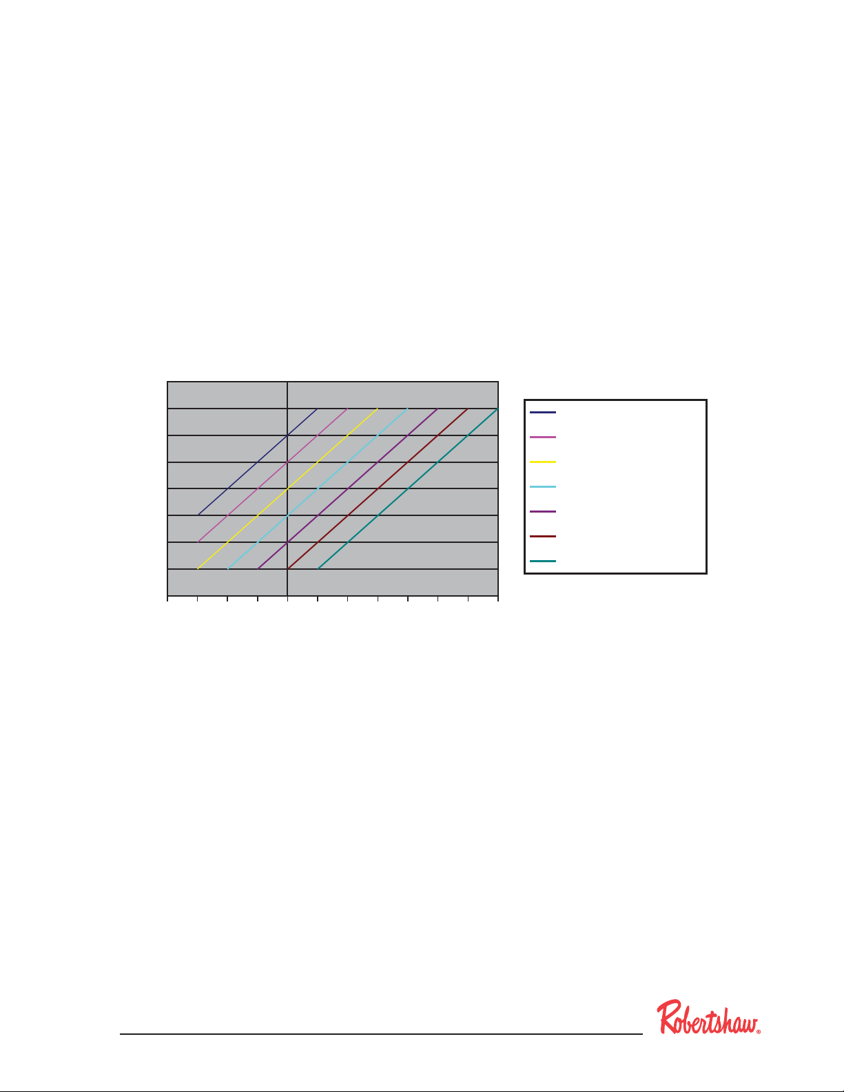
A bypass humidifier is installed with a down-flow furnace. The house temperature (setpoint is 73°F) is
75°F (The graph above shows that the automatic setpoint for RH is 30%, when the outdoor temperature
is 10°F). The thermostat is user selected to the Auto humidity setting.
The humidifier and fan activate adding moisture to the dwelling as needed to reach 32%RH. The
humidifier and fan will reactivate when the humidity drops below 28%RH. The setpoint is ±2%RH.
Condensation – If humidity levels cause condensation on windows, then this control needs to be adjusted.
This adjustment must be made over a 12-hour period to allow the humidity levels to stabilize.
For instance, by selecting –5% RH on the adjustment, the humidity will maintain 25% ± 2%RH with an
outdoor temperature of 10°F. If -5% is not enough to avoid condensation, then lower the Auto Humidity
Setting to -10%RH. The controlling RH will be 20%+ -2RH with an outdoor temperature of 10°F.
Recommended Settings
Auto Humidity Setting (AHS) +/- Dew Point Adjustment
50
45
40
35
30
25
20
Auto Humidity Setting
-40 -30 -20 -10 0 10 20 30 40 50 60 70
15
10
Outside Temperature °F
AHS + 15%
AHS + 10%
AHS + 5%
Auto Humidity Setting
AHS - 5%
AHS - 10%
AHS - 15%
Page 3

3
HUMIDIFIER TYPES
Bypass Humidifier
This humidifier takes heated air from the plenum, draws it through a water pad and deposits the moist
air in the return. The most common operation works with heat only. If the furnace is on only for a
short time, the humidified air cannot be distributed evenly through the house. In fact, the heat from
the furnace will remove moisture.
Power Humidifier
This humidifier takes air (room temperature or heated) from the plenum, draws it through a water pad
and forces the humidified air back into the plenum. This application allows more moisture to be distributed throughout the house. Some power humidifiers have transformers, and if this were the case, an
isolation relay would have to be installed. An isolation or heavy-duty relay is also needed if the current
draw of the power humidifier exceeds the 1 amp rating of the thermostat humidity relay contacts.
Mist or Steam Humidifier
This humidifier takes water or steam and sprays it into the plenum. Setting up this application is
critical, as the water may not fully evaporate.
DEHUMIDIFICATION
The D output is energized (24VAC) on no call for dehumidification.
When dehumidification is required, then D becomes deactivated (0 VAC). This is reverse logic.
Some control boards on furnaces (that have variable speed motors) have the D connection and look
for the voltage to maintain normal fan speed.
If the control board sees “0” VAC, then the control board automatically lowers the fan speed.
The 5-minute compressor short cycle time still applies in all modes of dehumidification.
COOLING
On a call for cooling, the thermostat will activate Y1 above the setpoint, and turn off below the setpoint
for a 1° differential (default). The differential is user adjustable (0.5, 1, 2, or 3°F) in 0.5° increments.
For multistage units, the second stage cooling (Y2) follows the on-off 2nd stage temperature
differentials. The default time (adjustable) is ten minutes.
MANUAL DEHUMIDIFICATION WITH COOLING
Dehumidification can become active only: 1) after the temperature rises to cause a cooling demand,
and, 2) the RH is still 2% above RH setpoint.
If room RH is 2% above the RH setpoint and cooling turns on, then the D terminal will be active or
de-energized (0 VAC). If dehumidification is successful before cooling requirements are met, then D
will switch to inactive (24 VAC present) while cooling continues.
The Y1, and D terminals will revert to their original state when room temperature has been reached.
The G terminal will remain on until the residual time off delay has timed out. (User selectable 0, 30, 60
or 90 seconds. Factory default is 30 seconds.)
Page 4

MANUAL INDEPENDENT DEHUMIDIFICATION
If RH rises 2% above RH setpoint, then D, G, and Y1 switch to active. (D becomes de-energized.) In
addition, the unit will operate until one of two requirements are met: Either the temperature decreases 1-1/2F° below the temperature setpoint or the RH decreases to 2% below the RH setpoint.
The resulting state depends on the room temperature at the time the dehumidication is satised. If
the temperature is in the range such that the cooling demand is satised, then Y1 and G turn off with
D. Otherwise there is a cooling demand from the present temperature, and Y and G stay active.
If dehumidication is active with no call for cooling, and cooling becomes active (Room temperature
is above temperature setpoint +0.5° F.), then the thermostat stays in a dehumidication state until the
humidity setpoint has been reached.
NOTE: If there is an existing xed speed motor and the dehumidication feature is used, see the
xed speed motor wiring diagram below.
Fixed Speed Motor
D Terminal
24 VAC
C Terminal
Relay Coil
Uni-Line Part #
600-293
Higher Speed
Fan
Motor
Lower Speed
Cool
Control
Board
D = 24 VAC – no call
D = 0 VAC – call
Relay shown in
de-energized state.
No voltage supplied.
191 E. North Avenue
Carol Stream Illinois 60188 USA
Customer Service Telephone 1.800.304.6563
Customer Service Facsimile 1.800.426.0804
HVACCustomerService@Invensys.com
4
For Technical Service
Telephone 1.800.445.8299
Facsimile 1.630.260.7243
TechnicalService@Invensys.com
®
Invensys
, Robertshaw® Uni-Line® and Simply the Right Choice™ are trademarks of
Invensys plc., its subsidiaries and/or affiliated companies. All other brands mentioned
may be the trademarks of their respective owners.
www.Uni-Line.com
www.InvensysControls.com
©2010 Invensys Controls
11/10 – 150-1992C
 Loading...