

Robertshaw 9020i, 9025i Install Sheet
Models 9701i, 9715i and 9720i
Quick Start Installation Manual
111-284D
Installation DOs and DON’Ts
DO
• Shut off all power to system before installing.
• Read entire manual before installing.
• Make sure that all wiring conforms to
national and local codes.
DO NOT
•
Install on voltages greater than 30 VAC.
• Short jumper across terminals on the gas
valve or at the system control.
• Connect ground to any terminal in
this unit.
• Install on outside walls or in direct sunlight.
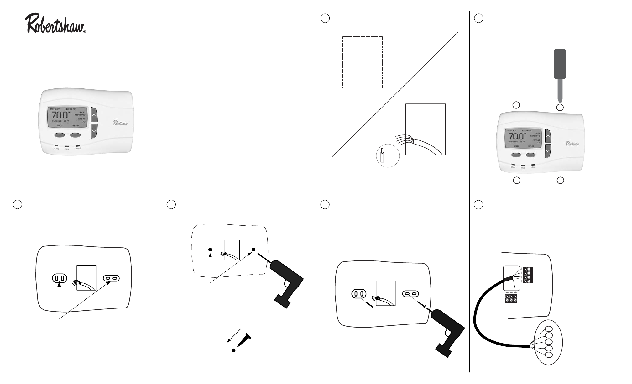
Select location for installation.
Open the case with a screwdriver. Place
in slot and gently pry forward at all four
locations.
Mark mounting hole locations on wall.
Drill 3/16” holes at marked locations on
wall. Insert plastic anchors into holes.
Align unit base over plastic anchors
embedded in wall and secure with the
screws provided.
Connect wiring between unit and
furnace. For Model 9701
i (1H/1C
gas/electric furnace).
DELUXE
Remove 1/2” of insulation
from end of each wire
PROGRAMMABLE
THERMOSTATS
1
1"
a
2
3
4
1-1/2"
5
Cut
out
opening
1/2"
b
2
4
6
1
3
Mark mounting hole
locations on wall using
unit base as template.
Drill 3/16 holes
a
b
Press anchors into holes until flush.
Thermostat
O B G
C
R
Y1
E/W1
9701i
TERMINAL DESIGNATIONS
C - 24VAC Common
R - 24VAC
Y1 - 1st stage cooling
E/W1- 1st stage heating
O - Not used
B - Not used
G - Fan
G
Equipment Wiring
Y
Terminals
R
Please refer to furnace
W
installation manual for
C
proper terminations.
NOTE: For 9701i single stage heat
pump applications, place a jumper
between the E/W1 and Y1 terminals.
7
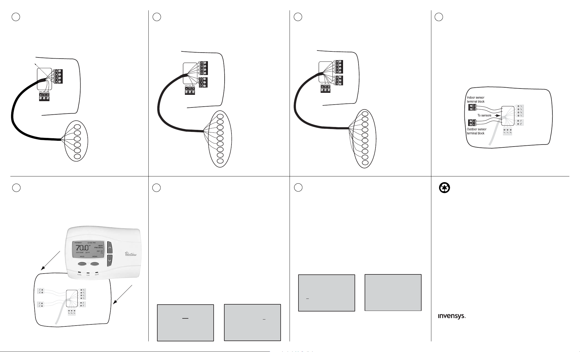
Connect wiring between unit and
furnace. For Model 9715i (2H/2C
gas/electric furnace applications).
Replace cover on thermostat.
Turn on power to unit and proceed
with programming per instructions on
the display or in the user’s manual.
Connect wiring between unit and
furnace. For Model 9720i (2H/2C
heat pump with furnace or strip heat).
To set your name and phone
number into the thermostat press
MENU, select INSTALLER
SETTINGS, and CONTACT
INFORMATION. The screen at the
bottom left should appear.
To enter your name press EDIT.
Use the UP or DOWN button to
scroll through the characters.
(DOWN gets you to the letters
faster.) After each letter press NEXT.
When you are done entering your
name, press ACCEPT.
Connect wiring between the thermostat and the indoor sensor (9020i)
and the outdoor sensor (9025i), if
used. Use twisted pair wiring (22AWG
minimum) with a maximum length of
300 feet (or 100m).
Now enter your phone number.
Use the UP and DOWN arrow to
select the first number. Press NEXT.
When you have completed entering
your phone number, press ACCEPT.
The screen will return to the
INSTALLER SETTINGS. Finish
setting the thermostat for the
application.
Controls Americas
515 South Promenade Avenue
Corona, CA 92879-1736
United States of America
Made in Mexico
www.about-i-series .com 111-284D
Set Your Name Set Your Phone Number
Recycling Thermostat
If this thermostat REPLACES a thermostat that contains mercury,
DO NOT discard the old thermostat in the regular trash. Mercury
is harmful to humans and the environment. For this reason, do not
open, break, or crush the mercury cell. If mercury leaks from a
damaged cell, DO NOT touch or handle mercury with bare hands.
Use protective, non-absorbent gloves to place mercury into a
sealable container. Fill the container with sand or another
absorbent material and seal the container completely.
Return the mercury or mercury products, in a sealed container, to
Invensys Climate Controls or a local recycling center for proper
disposal. If you have any questions, call Robertshaw technical
support at 1-800-445-8299.
In U.S.:
Invensys Controls Americas
28C Leigh Fisher Blvd.
El Paso, TX 79906
Attn: Mercury Recycling Center
In Canada:
Invensys Controls Americas
3515 Laird Road - Unit #14
Mississauga, Ontario L5L 5Y7
Attn: Mercury Recycling Center
Jumper Wire
Thermostat
O B G
C
R
Y1
E/W1
9701i
TERMINAL DESIGNATIONS
C - 24VAC Common
R - 24VAC
Y1 - 1st stage cooling
E/W1- 1st stage heating
O - Reversing valve (cool)
B - Reversing valve (heat)
G - Fan
Equipment Wiring
G
Terminals
Y1
Please refer to heat
R
pump installation
C
manual for proper
B
terminations.
O
8
9
Thermostat
O B G
C
R
Y1
E/W1
W2
Y2
L
9715i
TERMINAL DESIGNATIONS
C - 24VAC Common
R - 24VAC
Y1 - 1st stage cooling
E/W1 - 1st stage heating
W2 - 2nd stage heating
Y2 - 2nd stage cooling
L - Not used
O - Not used
B - Not used
G - Fan
C
R
Y1
Equipment Wiring
W1
Terminals
W2
Please refer to furnace
Y2
installation manual for
G
proper terminations.
O
B
If terminal E is not supplied,
add jumper across E/W1
and W2 on the thermostat.
Thermostat
O B G
C
R
Y1
E/W1
W2
Y2
L
9720i
TERMINAL DESIGNATIONS
C - 24VAC Common
R - 24VAC
Y1 - 1st stage heating/cooling
E/W1 - Emergency heat strip
W2 - 2nd stage heating
Y2 - 2nd stage cooling
L - System fault indicator
O - Cool active reversing valve
B - Heat active reversing valve
G - Fan
C
R
Y1
Equipment Wiring
E
Terminals
W2
Please refer to heat
Y2
pump installation manual
L
for proper terminations
G
B
O
10
11
1
2
CONTACT INFORMATION
BACK
EDIT
CONTACT INFORMATION
AIR EXPERTS
ACCEPT
NEXT
13
CONTACT INFORMATION
AIR EXPERTS
1
ACCEPT
NEXT
CONTACT INFORMATION
AIR EXPERTS
1-555-555-1212
ACCEPT
NEXT
 Loading...