

Page 1

F
2317 (R
Sales Manual Section 332
PRODUCT SPECIFICATION PS 83939-E
Lockout Relay
83939-E1
GENERAL DESCRIPTION
The No. 83939-E1 Lockout Relay is a two-way,
diaphragm-actuated, non-venting, normally open
valve. It is used in the safety system to lock out or
block certain portions of the control system or a line in
a control system upon receipt of a signal at PORT 1.
(See Figure 1). It will reopen with the loss of pressure
at PORT 1, and has a connection which may be used to
cancel the actuating pressure at PORT 1.
SPECIFICATIONS
Construction:
Aluminum body; stainless steel cover,
bracket and springs; elastomer coated fabric
diaphragms and gaskets; stainless steel and
aluminum valve with resilient seat.
Supply Pressure: ...........................................
CAUTION: DO NOT EXCEED MAXIMUM PRESSURES
Maximum Pressure: ......................................
Mounting: .................................................................
Dimensions: ...................................................
Connections: ................................................
Approximate Shipping Weight: .............
Ordering Information:
See Figure 2.
See Figure 2.
Surface
See Figure 1.
1/8"-27 NPT.
12 ozs. (.340 kg)
Specify: No.
83939-E1
INSTALLATION
A. General
Tubing and fittings used to connect the relay
must be free of chips, dirt, and moisture or other
foreign material.
It is recommended that an "anti-seize" type
thread compound be applied to the second or third
male thread in moderate amount. Do not allow
compound to be deposited inside the relay. Thread
sealing tape is not recommended.
For continuous, trouble-free operation, the
supply to the relay must be clean and dry.
*AIR OR GAS
J. I. C. Symbol
B. Mounting
When installing the No. 83939-E 1 Lockout
Relay,
care should be taken to prevent any foreign matter
from entering the ports. Provisions should be
made to
prevent foreign matter from entering the ports
which are left open to the atmosphere.
The relay may be installed in any position, but
vertical (upright) is recommended. The relay
should be
securely mounted, using the two slots (clearance
for No. 10 screws), provided in the mounting
bracket (See Figure 1).
orm No. P-
ev. B)
1
Page 2
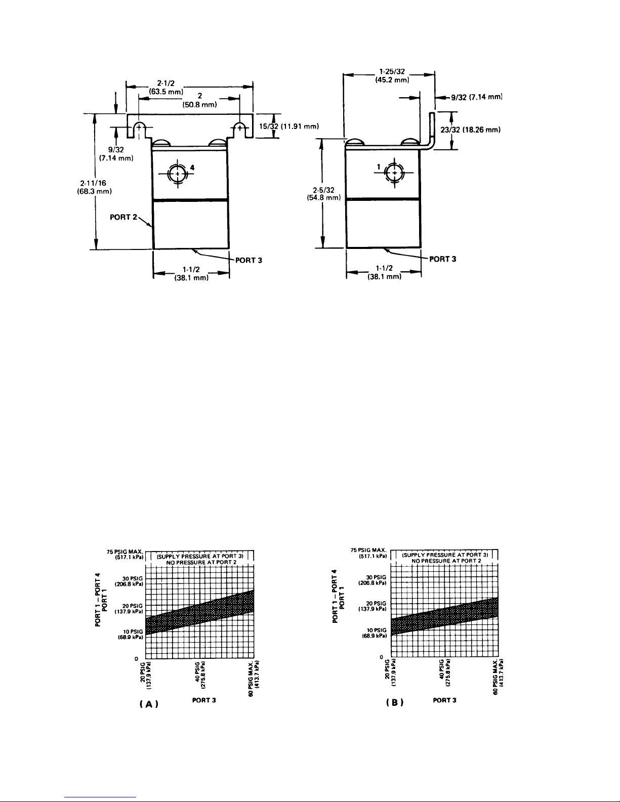
DIMENSIONS
NOTE
NOTE
Figure 1
OPERATION (See Figure 3 )
With no pressure applied to the diaphragm
through Port 1, Port 3 (supply port) is connected
through this normally open relay to Port 2.
When sufficient pressure is applied to the
diaphragm through Port 1, the stem moves down and
forces the lower poppet on seat,
: Graph A indicates actuating pressure (Port
1) required to keep valve closed at various
supply pressures (Port 3). Also, Graph A
indicates actuating pressure (Port 1) minus
equalizing pressure (Port 4) required to
keep valve closed at various supply
pressures (Port 3).
closing Port 3 to Port 2. Loss of pressure through Port
1 will allow the stem to return to its original position.
At the same time, the lower spring will force the
lower poppet off seat, opening Port 3, again, to Port
2. Also, the relay may be reopened by applying an
equalizing pressure through Port 4.
: Graph B indicates decreasing actuating
pressure (Port 1) required to open valve at
various supply pressures (Port 3). Also,
Graph B indicates decreasing actuating
pressure (Port 1) minus equalizing
pressure (Port 4) required to permit same
action.
CAUTION: DO NOT EXCEED MAXIMUM PRESSURES.
Figure 2
2
Page 3

Figure 3
Figure 4
MAINTENANCE
WARNING: Disassemble carefully - spring load
forces present.
A. If excessive leakage occurs at valve seat,
disassemble the relay. Clean poppet and seat with
soft, dry cloth (See Figure 4).
B. If relay does not function properly due to
contamination by foreign matter, disassemble and
clean all metal parts with non-flammable solvent
and dry thoroughly.
C. After reassembly, check for external leakage.
Retighten assembly screws as necessary. Gasket
cement should not be used to seal leaks due to the
possibility of plugging small passages or
damaging the operating characteristics of the
diaphragms.
CAUTION:
If cleaning is required, do not subject "O" rings,
valve poppets, diaphragms or gaskets to cleaning
fluid, acetone, or any halogenated hydrocarbons such
as vapor degrease liquids, etc. Clean only with a soft,
dry cloth.
Upon reassembly, all "O" rings are to be
lubricated with a silicone-type lubricant. Do not
permit lubricant to get on poppet or valve seats.
3
Page 4

PARTS LIST
PARTS LIST
DET.
NO.
NO.
REQ’D
DESCRIPTION
DWG.
NO.
1 4 Screw 33713-H2409
2 4 Lockwasher 36600-L0609
3 1 Mounting Bracket 24637-C2
4 1 Relay Body 31857-E1
5 1 Head & Stem
85013-81
Assembly
6 1 O-Ring 36240-C10
7 1 Plug & Guide
99264-B1
Assembly
8 1 Nameplate 30036-G2
9 1 Relay Body 31857-D1
10 1 Spring 25121-A1
11 2 Gasket 33665-B 1
12 1 Spring 24598-A1
13 1 Diaphragm 24498-A1
14 1 Spacer 33430-A2
NOTE: For complete kit containing all "O" Rings, gaskets,
diaphragms, and poppet to service one unit, order Repair Kit No.
82665-B3. Repair Kit includes Details 6,7,11 and 13 - also
instruction manual and lubricant.
4
Q-3580 (5/01) Printed in U.S.A.
 Loading...