

Page 1
Industrial Products Division
Model 570B Series
T wo-wir e Vibration Sensor
SPECIFICATIONS
Robertshaw Industrial Products Division
1602 Mustang Drive
Maryville, Tennessee 37801 Telephone:
(865) 981-3100
Fax: (865) 981-3168
FEATURES:
• Corrosion resistant
• ESD protection
• Reverse wiring protection
• Overload protection
• Hermetic
• No trim pots
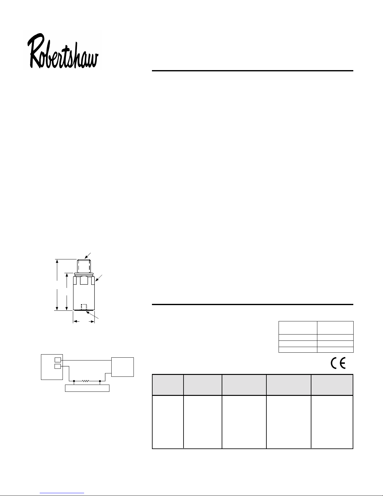
2 pin
connector
1 1/16" hex
2.80"
2.12"
DYNAMIC
Output (±5% of Full Scale) ............................................. 4-20 mA DC
Vibration Range ............................................................. see table below
Frequency Response:
–3 dB ..................................................................... see table below
Repeatability .................................................................. ±2%
Resonant Frequency, mounted, nominal ....................... see table below
Transverse Sensitivity, max. .......................................... 5%
ELECTRICAL
Power Requirements (Two wire loop power):
voltage source........................................................ 10 VDC - 30 VDC
Loop Resistance
1
at 24 VDC, maximum........................ 700Ω
Turn on Time.................................................................. <30 seconds
Grounding ...................................................................... Case isolated, internally
shielded
ENVIRONMENTAL
Temperature Range....................................................... –40 to 85 °C
Vibration Limit ................................................................ 250 g peak
Shock Limit .................................................................... 2,500 g peak
Electromagnetic Sensitivity, equiv. g ............................. 10 µg/gauss
Sealing ........................................................................... hermetic, NEMA 4X, IP68
PHYSICAL
Weight............................................................................ 162 grams
Sensing Element Design................................................ PZT ceramic / shear
Case Material................................................................. 316L stainless steel
Mounting ........................................................................ 1/4 - 28 tapped hole
Output Connector........................................................... 2-pin, MIL-C-5015 style
Pin A ............................................... plus (+) White
Pin B .............................................minus (–) Black
2
Cabling
......................................................................... Two conductor shielded
(See Table 1 on back)
Torque Limit................................................................... 30 in lbs. max
Warranty ........................................................................ 1 year
1/4-28
Model 570
1.12"
Typical Circuit
Pin A
+
Pin B
–
Signal Measuring Circuit
R
LOAD
mounting hole
+
DC Power
Supply
–
Due to continued research and development, the Manufacturer reserves the right to amend these specifications without notice.
NOTES:
1
Maximum loop resistance can be calculated by:
Typical
RL (max) = -------------------------
Vpower – 10 V
20 mA
Loop resistance is the sum of wiring
resistance and the load resistor.
2
Cable resistance equals 40 ohms, total per 1000 ft.
Power Source RL max
Voltage
20 500
24 700
26 800
ACCESSORIES SUPPLIED: 1/4-28 mounting stud.
Model Mode Range Frequency Resonant
Response Frequency
570B-A acceleration 0 - 5 g peak 2 Hz - 2 kHz 28 kHz
570B-B acceleration 0 - 10 g peak 2 Hz - 2 kHz 28 kHz
570B-C acceleration 0 - 20 g peak 2 Hz - 2 kHz 28 kHz
570B-D velocity 0 - 0.5 IPS peak 2 Hz - 2 kHz 28 kHz
570B-E velocity 0 - 1 IPS peak 2 Hz - 2 kHz 28 kHz
570B-F velocity 0 - 2 IPS peak 2 Hz - 2 kHz 28 kHz
TABLE
98549 Rev.G.1 1/04
Page 2
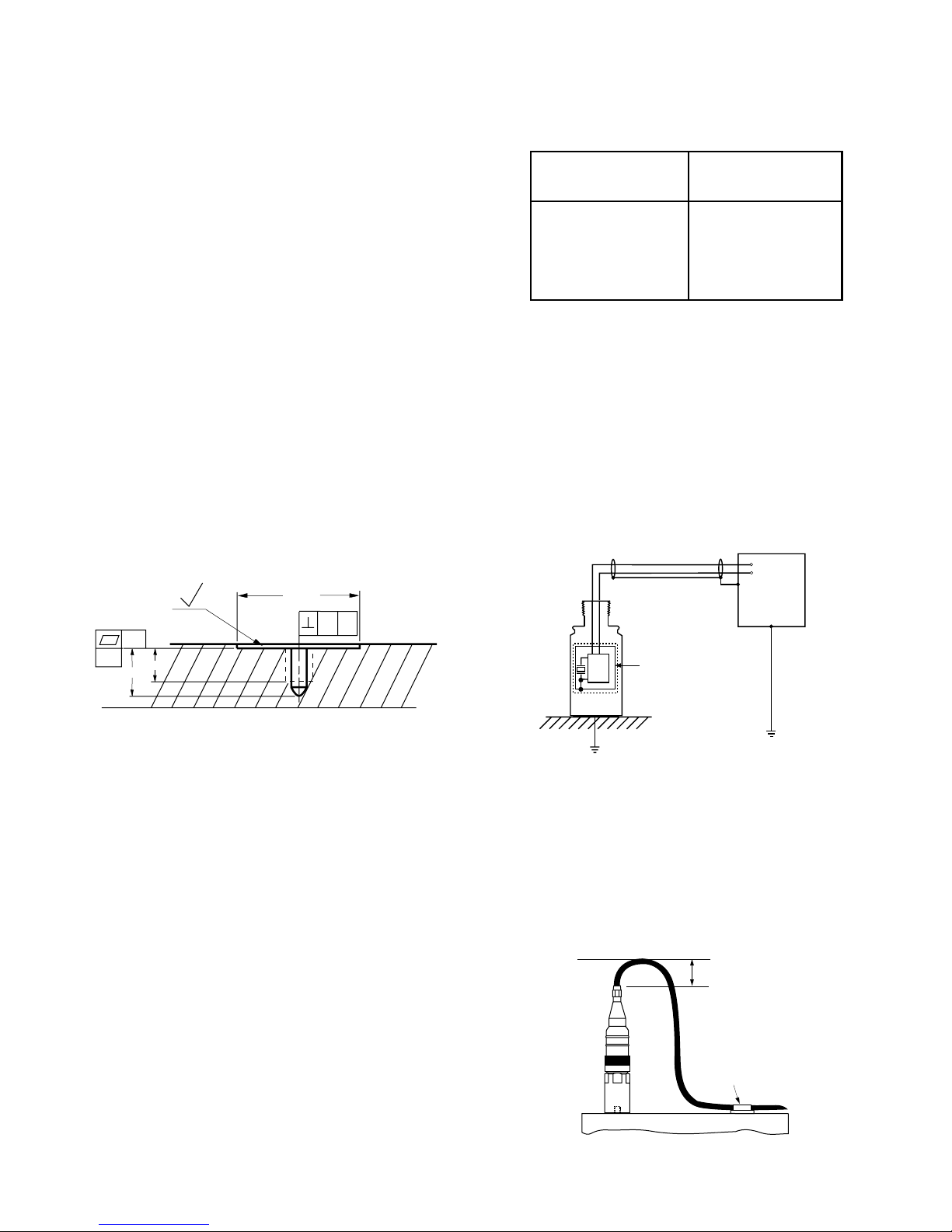
Mounting Instructions
The mounting point on the structure should be faced to a
diameter of 1.25 inches. For measurements involving
frequencies above 1 kHz, the surface should be flat within 1
mil and have surface texture no greater than 32 microinches.
The tapped hole must be perpendicular to the mounting
surface and at least two threads deeper than the stud. This will
prevent a gap between the sensor and the mounting surface–
producing optimum frequency response. (see Figure 1).
Proper screw torque on the mounting stud is also required.
Under-torquing the sensor reduces the stiffness of the
coupling. Over-torquing can cause permanent damage to the
sensor. It is recommended that 1/4-28 stud be torqued to a
maximum value of 30 inch-pounds.
Table 1: Cable versus Cable Length
Part Number NEMA 4X
Cable Length
086568A0016 16 Ft.
086568A0032 32 Ft.
086568A0064 64 Ft.
086568A0112 112 Ft.
Note: IP68 cable available by special order.
Cable Grounding and Ground Loops
In order to provide proper shielding and prevent ground
loops, cable grounding should be carefully considered.
Before stud mounting the sensor, a coupling fluid should be
applied to the mating surfaces. The coupling fluid protects the
mounting surface and optimizes the frequency response by
increasing the coupling stiffness. Suggested coupling fluids
are machine oil or vacuum grease. It is recommended that a
thread adhesive such as Loctite 222 be used.
—A—
.001
.35
Surface
Facing
.25
32
1.25" min.
.004
A
Figure 1: Stud Mounting: Surface Preparation
Cable Routing and Electromagnetic Interference
Walkie-talkies, power lines, or even electrical sparks may
cause signal interference. The following guidelines will
eliminate many measurement errors due to electromagnetic
radiation and electrostatic discharge (ESD).
Assure that high quality, well shielded cables are used. If
cable splices are made, complete shielding must be
maintained.
Proper cable routing is imperative. Never run sensor cable
alongside AC power lines; cables must cross AC power lines
at right angles. Where possible, provide a separate grounded
conduit to enclose the sensor cable. In addition, route the
cable away from radio transmission equipment, motors/
generators, and transformers. Finally, avoid routing the cable
through areas prone to ESD. Even though Robertshaw
sensors are protected against ESD failure, temporary
distortion signals may appear at the output.
For sensors using two conductor/shielded cable, the power is
carried on one lead and the return on the other. The cable
shield serves to protect the signal from ESD and
electromagnetic interference (EMI). The shield should be
grounded at only one point. Figure 2 shows a typical cable
connection scheme.
+
–
Readout
Equipment
Electronics
Internal Shield
Isolated from Housing
Figure 2: Multiconductor/Shield Configuration
Cable Anchoring
After mounting the sensor, the cable should be anchored to
reduce stress at the cable terminations. When securing the
cable, leave enough slack to allow free movement of the
sensor. Figure 3 shows a recommended cable anchoring
technique.
Allow 2 inches
minimum bend
radius
Cable
Clamp
Machine Surface
Figure 3: Cable Anchoring
 Loading...