

Page 1
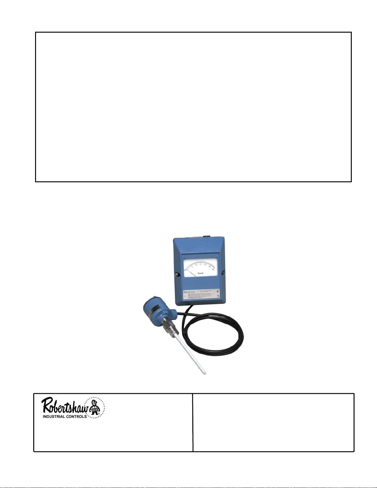
MODEL 158A 909GF197B
INSTRUCTION MANUAL
MODEL 158A
LEVEL-TEL
FOR
We do our level best
Industrial Products Division
1602 Mustang Drive
Maryville, Tennessee 37801
Phone: (865) 981-3100 Fax: (865) 981-3168
- 1 -
Probe, Cable and Conduit Outlet Box
shown for illustration only.
Must be ordered separately.
INSTRUCTION MANUAL NUMBER
909GF197B
P-2410
Page 2
MODEL 158A 909GF197B
Section I – DESCRIPTION
1.1 GENERAL
The Robertshaw Model 158A Level-Tel is a
capacitance operated DC current transmitter with
noninteracting and independent zero and span
adjustments internally located. The transmitter is
remotely mounted from the probe with a triax
cable interconnected between the probe and the
transmitter.
1.2 MODEL IDENTIFICATION
Identify instrument models in accordance with the
descriptions and variations listed in each table.
158A - B 1 - A 1
Key Model No.
Table 1 – Output Current
Table 2 – Supply Voltage
Table 3 – Display Housing and Indication
Table 4 – Alarm Options
KEY MODEL NO.
Model
No.
158A Capacitance-to-current transmitter
system for remotely mounted probe
assemblies. Control Unit is
available with or without indication
and optional alarms.
Table 1 – OUTPUT CURRENT
Desig. Description
A 1-5 mADC
B 4-20 mADC
C 10-50 mADC
D 0-10 mADC
Table 2 – SUPPLY VOLTAGE
Desig. Description
1
2
3
26.5 VDC, ± 10%
120 VAC, ± 10%, 50/60 Hz
240 VAC, ± 10%, 50/60 Hz
Description
¾ May only be used with Designation E on
Table 3.
Table 3 – DISPLAY HOUSING AND
INDICATION
Desig. Description
A Water tight enclosure without
indicator.
Meets NEMA Type 4 and CSA
Enclosure 5.
B Water tight housing with indicator.
Meets NEMA Type 4 and CSA
Enclosure 5.
C Explosion proof housing without
indicator.
For Class I, Division 1, Groups C
and D; Class II, Division 1, Groups
E, F and G, areas.
D Explosion proof housing with
indicator.
For Class I, Division 1, Groups C
and D; Class II, Division 1, Groups
E, F and G, areas.
E Large weatherproof enclosure with
indicator to be used with optional
alarms.
Meets NEMA Type 12 & 13 and
CSA Encl 3.
Table 4 – ALARM OPTIONS
Desig. Description
1 None
2 ¾Alarm Relays for High or Low
Alarm.
3 ¾Alarm Relays for High and Low
Alarms.
- 2 -
Page 3
MODEL 158A 909GF197B
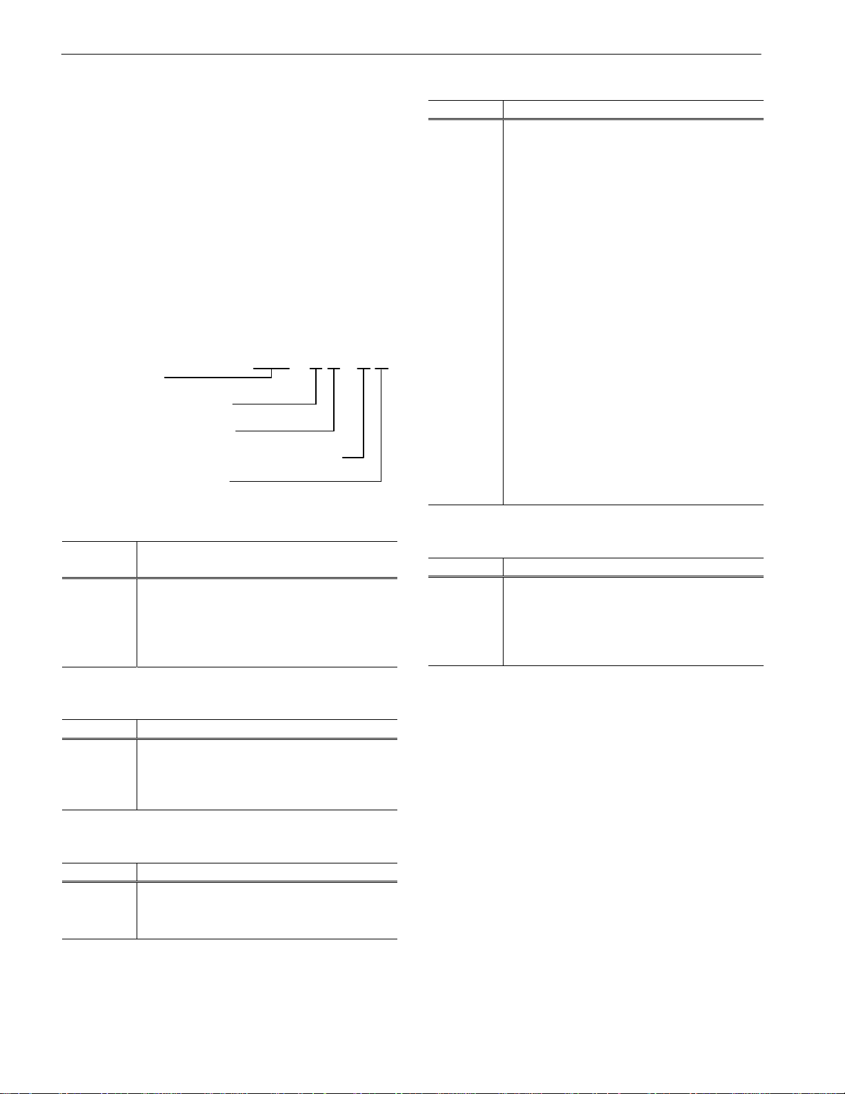
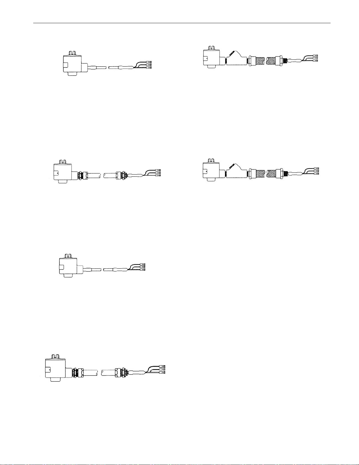
1.3 TRIAXIAL CABLE ACCESSORY ITEMS
032KE03X-XX¾
GENERAL PURPOSE (polyethylene insulated)
Triax Cable with probe connection conduit
outlet box. (Recommended for use with
customer supplied rigid or flexible conduit.)
Maximum temperature 185° F.
032KE05X-XX¾
GENERAL PURPOSE (polyethylene insulated)
Triax Cable in flexible conduit (protective
armor) with probe connection conduit outlet
box. Maximum temperature 185° F.
032KE04X-XX¾
HIGH TEMPERATURE (Teflon insulated) Triax
Cable with probe connection conduit outlet box.
(Recommended for use with customer supplied
rigid or flexible conduit.) Maximum
temperature 350° F.
032KE06X-XX¾
HIGH TEMPERATURE (Teflon insulated) Triax
Cable in flexible conduit (protective armor) with
probe connection conduit outlet box. Maximum
temperature 350° F.
032KE090-05 (5 ft long)
032KE090-10 (10 ft long)
GENERAL PURPOSE (polyethylene insulated)
Triax Cable in explosion proof flexible conduit
(protective armor) with seal fitting and probe
connection conduit outlet box. Maximum
temperature 185° F.
032KE100-05 (5 ft long)
032KE100-10 (10 ft long)
HIGH TEMPERATURE (Teflon insulated) Triax
Cable in explosion proof flexible conduit
(protective armor) with seal fitting and probe
connection conduit outlet box. Maximum
temperature 350° F.
¾ Substitute length in feet for X-XX in part
number.
Example: For 10 feet substitute 0-10
For 120 feet substitute 1-20
Explosion proof cables are standard in 5 and
10 foot lengths.
- 3 -
Page 4

MODEL 158A 909GF197B
Section II - SPECIFICATIONS
2.1 ENVIRONMENTAL
Ambient Temperature Limits.......-40° F to +160° F
Vibration Limits................± 2 G from 10 to 200 Hz
2.2 ELECTRICAL
Supply Voltage............. 120 VAC ± 10%, 50/60 Hz
240 VAC ± 10%, 50/60 Hz
26.5 VDC ± 10%
2.4 ENCLOSURE
Water Tight ...............NEMA 4, CSA Enclosure 5,
Polyurethane painted cast aluminum
Explosion Proof...Class I, Division 1, Groups C, D;
Class II, Division 1, Groups E, F, G;
Polyurethane painted cast aluminum
Weatherproof..... NEMA 12, 13, CSA Enclosure 3,
Polyurethane painted steel
2.5 INTRINSIC SAFETY
Models 158A – (A, B) (1, 2) – (A, B, C, D) – 1:
Supply Power........................... 5 watts, 7 VA max.
Terminal Capacitance Range............ 0 to 1000 pF
Probe circuit is CSA Certified intrinsically
safe for Class I, Division 1, Group C & D;
Class II, Division 1, Group E, F & G
Span Capacitance Range........ 10 pF plus 1 pF for
each 10 feet of Triax
cable up to 2000 pF
Maximum Recommended
Terminal/Span Ratio....................................... 10:1
Output Signal
and Load...................1-5 mADC into 0-2500 ohms
4-20 mADC into 0-700 ohms
10-50 mADC into 0-250 ohms
0-10 mADC into 0-1000 ohms
hazardous locations when connected as
shown on drawing 907GA518 (Figure 8).
2.6 AGENCY CERTIFICATIONS
Models 158A – (A, B) (1, 2) – (A, B, C, D) – 1:
CSA Certified .............................File LR 18690
Connecting Cable Length.................150 feet max.
2.3 PERFORMANCE
Linearity.................................. 0.5% max. for span
less than 1000 pF
1% max. for span
greater than 1000 pF
Repeatability...............................................± 0.1%
Sensitivity......................................0.01% minimum
Frequency Response.........................-3 db at 1 Hz
Supply Variation Effect ...............0.5%/10% supply
Ambient Temperature Effect:
Span................................................0.01%/° F
Zero............................. 0.01%/F or 0.01 pF/F,
whichever is greater
Output Signal Ripple............................. 0.2% max.
Output Meter Accuracy.................................. ± 2%
- 4 -
Page 5

MODEL 158A 909GF197B
Section III - INSTALLATION
3.1 GENERAL
Examine the instrument for possible shipping
damages. IMPORTANT: If for any reason it is
determined that parts should be returned to the
factory, please notify the nearest Robertshaw
sales representative prior to shipment. Each unit
must be properly packaged to prevent damage.
Robertshaw assumes no responsibility for
equipment damaged in shipment due to improper
packaging.
Choose the location in accordance with good
instrument practice, avoiding extremes of
temperature, humidity and vibration (see
Specifications, Section II).
3.2 PROBE MOUNTING
3.3 TRANSMITTER UNIT MOUNTING
The Model 158A is designed for vertical surface
mounting: e.g. wall, panel or column. Choose the
mounting location to avoid extremes of ambient
temperature or vibration (see Specifications,
Section II).
3.4 WATER TIGHT & WEATHERPROOF
TRANSMITTER MOUNTING & ELECTRICAL
CONNECTIONS
See Figures 1, 3, 4, 5, 6 and 7 for the mounting
dimensions and electrical connections of the
Water Tight and Weatherproof Transmitters. See
Figure 8 for interconnection diagram for those
models certified for intrinsically safe probe
installations.
3.5 EXPLOSION PROOF TRANSMITTER
MOUNTING & ELECTRICAL CONNECTIONS
Level-Tel probes for use with the Model 158A are
purchased separately from a variety of styles and
types which provide for various specific
applications involving liquids or granular
materials. Insulated rod-type probes are normally
used for liquid solutions or liquid-interface
junctions.
Since many materials have a tendency to build up
on the probe over extended periods of operation,
it is advisable on horizontally mounted probes to
place the probe so that its lower tip is below the
gland entrance. This encourages self-cleaning by
permitting the material to drip from the probe.
However, some materials will continue to build up
and cause the Level-Tel to become insensitive or
fail to operate. If such material is being used, the
installation should be made so that the probe is
easily removed for periodic cleaning.
The face of the gland on the rod-type probes
must be installed until nearly flush with the vessel
wall. DO NOT install the probe in a nozzle,
recess, or open-end well, unless the probe was
supplied with a factory assembled sheath as
there is danger of material collecting in such a
recess and causing false operation.
- 5 -
See Figures 2, 3 and 5 for the mounting
dimensions and electrical connections of the
Explosion Proof Transmitter. See Figure 8 for the
interconnection diagram for those models certified
for intrinsically safe probe installations.
Page 6

MODEL 158A 909GF197B
MM
INCHES
SEE FIGURE 5 FOR DIMENSIONS OF
PROBE MOUNTED CONDUIT OUTLET BOX.
MOUNTING DIMENSIONS FOR MODEL 158A WATER TIGHT ENCLOSURE WITH
AND WITHOUT INDICATOR, MODELS 158A – ( ) ( ) – A1 AND 158A – ( ) ( ) B1.
FIGURE 1
- 6 -
Page 7

MODEL 158A 909GF197B
FIGURE 2
MOUNTING DIMENSIONS FOR MODEL 158A EXPLOSION PROOF ENCLOSURE WITH
AND WITHOUT INDICATOR, MODELS 158A – ( ) ( ) – C1 AND 158A – ( ) ( ) – D1.
MM
INCHES
SEE FIGURE 5 FOR DIMENSIONS OF PROBE
MOUNTED CONDUIT OUTLET BOX.
- 7 -
Page 8

MODEL 158A 909GF197B
TERMINAL CONNECTION REMARKS
NOTES:
1
PROBE TRIAX WHITE LEAD
SHLD TRIAX RED LEAD
GND TRIAX BLACK LEAD
1 N ( ) SUPPLY
2 H (+) SUPPLY
GND CHASSIS GROUND
3 ( ) OUTPUT SIGNAL
4 (+) OUTPUT SIGNAL
. REMOVE JUMPER ACROSS OUTPUT TERMINALS 3 AND 4 WHEN RECORDER,
CONTROLLER, ETC. IS USED.
TERMINAL
FIGURE 3
ELECTRICAL CONNECTIONS FOR WATER TIGHT AND EXPLOSION PROOF ENCLOSURES,
MODELS 158A – ( ) ( ) – (A, B, C, D) ( ).
SEE RATING PLATE
(120 VAC, 240 VAC OR 26.5 VDC)
SEE NOTE 1
- 8 -
Page 9

MODEL 158A 909GF197B
MOUNTING DIMENSIONS FOR LARGE WEATHERPROOF ENCLOSURE WITH INDICATOR (USED WITH
OPTIONAL ALARMS) MODEL 158A – ( ) ( ) – E ( ).
FIGURE 4
MILLIMETER
INCH
SEE FIGURE 5 FOR DIMENSIONS OF PROBE
MOUNTED CONDUIT OUTLET BOX.
- 9 -
Page 10

MODEL 158A 909GF197B
–
( ) ( )
FIGURE 5
DIMENSIONS OF PROBE MOUNTED CONDUIT OUTLET BOX SUPPLIED WITH TRIAX CABLE.
(TRIAX CABLE ORDERED SEPARATELY)
ELECTRICAL CONNECTIONS FOR LARGE WEATHERPROOF ENCLOSURE,
MODEL 158A
FIGURE 6
–E ( ).
- 10 -
Page 11

MODEL 158A 909GF197B
TERMINAL CONNECTION REMARKS
TB2
TB7
TB8
TB9
PROBE TRIAX WHITE LEAD
SHLD TRIAX RED LEAD
GND TRIAX BLACK LEAD
G CHASSIS GROUND
1 N ( ) SUPPLY
2 H (+) SUPPLY
3 ( ) OUTPUT
4 (+) OUTPUT
5
6
7
NO CONNECTION SEE NOTE 5
8
9 N.C.
10 COM.
11 N.O.
12 N.C.
13 COM.
14 N.O.
15
16
NO CONNECTION
17 N.C.
18 COM.
19 N.O.
20 N.C.
21 COM.
22 N.O.
FIELD WIRING
NOTES:
1. THE ALARM RELAY CONTACTS ARE SHOWN IN THE DE-ENERGIZED CONDITION. FOR
NORMAL OPERATION THE RELAY IS ENERGIZED AND BECOMES DE-ENERGIZED WHEN
THE OUTPUT SIGNAL REACHES THE ALARM POINT.
2. REMOVE JUMPER ACROSS OUTPUT TERMINALS 3 AND 4 WHEN RECORDER,
CONTROLLER, ETC. IS USED.
3. UNLESS OTHERWISE SPECIFIED ALARM NO. 1 SUPPLIES HLFS.
4. UNLESS OTHERWISE SPECIFIED ALARM NO. 2 SUPPLIES LLFS.
5. TERMINALS 3 AND 4, 5 AND 6, 7 AND 8 ARE NORMALLY JUMPERED TOGETHER.
FIGURE 7
ELECTRICAL CONNECTIONS FOR LARGE WEATHERPROOF ENCLOSURE,
MODEL 158A – ( ) ( ) – E ( ).
SEE RATING PLATE
(120 VAC, 240 VAC OR 26.5 VDC)
SEE NOTES 2 AND 5
OPTIONAL NO. 1 ALARM CONTACTS
SEE NOTES 1 AND 3
OPTIONAL NO. 2 ALARM CONTACTS
SEE NOTES 1 AND 4
- 11 -
Page 12

MODEL 158A 909GF197B
–
(
–
(
NOTES:
1. IN FIGURE 1, THE TRANSMITTER IS CSA CERTIFIED FOR HAZARDOUS LOCATIONS, CLASS I, DIVISION 1, GROUPS C & D;
CLASS II, DIVISION 1, GROUPS E, F & G. THE PROBE IS INTRINSICALLY SAFE FOR CLASS I, DIVISION 1, GROUPS A, B, C &
D; CLASS II, DIVISION 1, GROUPS E, F & G.
IN FIGURE 2, THE TRANSMITTER IS CSA CERTIFIED FOR ENCLOSURE 5. THE PROBE IS INTRINSICALLY SAFE FOR
CLASS I, DIVISION 1, GROUPS A, B, C & D; CLASS II, DIVISION 1, GROUPS E, F & G.
2. R. STAHL INC., MODEL 8901/33-293/000-79 OR CSA CERTIFIED EQUIVALENT (28.1V MAX., 300 OHM MIN.) POSITIVEPOTENTIAL SIGNAL RETURN LINE BARRIER WITH INTRINSICALLY SAFE TERMINALS 2 (GROUND) AND 3. BARRIER MUST
BE MOUNTED AND GROUNDED OUTSIDE THE HAZARDOUS AREA IN ACCORDANCE WITH THE INSTRUCTIONS PACKED
WITH BARRIER. POTENTIAL TO GROUND MUST NOT EXCEED 250V RMS (360V PEAK).
3. ROBERTSHAW MODELS 158A – (A, B) (1, 2) – (C, D) 1.
4. ROBERTSHAW MODELS 158A – (A, B) (1, 2) – (A, B) 1.
5. ROBERTSHAW MODEL 702, 728, 729, 736, 738, 739, 740 0R 741 PROBE. INSULATED PROBES ONLY MAY BE USED IN
CLASS II, GROUPS E & F AREAS.
6. 650 OHMS MAXIMUM TOTAL LOOP RESISTANCE, EXCLUDING BARRIER RESISTANCE.
7. FOR AN INTRINSICALLY SAFE INSTALLATION, ALL WIRING BETWEEN THE BARRIER AND THE TRANSMITTER MUST BE
INSTALLED IN RIGID METAL CONDUIT.
FIGURE 8 – DRAWING 907GA518
- 12 -
DIAGRAM FOR INTRINSICALLY SAFE INTERCONNECTIONS FOR
MODELS 158A
A, B) (1, 2)
A, B, C, D) 1.
Page 13

MODEL 158A 909GF197B
Section IV – OPERATION
4.1 CALIBRATION ADJUSTMENTS
Alarm Module No. 2. Refer to Figure 9 and the
following paragraphs for detailed instructions on
how to change the links to obtain the desired
mode. The supply voltage to the instrument
All the adjustments for calibrating the Model 158A
Level-Tel are located on the printed circuit board
assembly and consist of the following (see Figure
8):
4.1.1 Zero Adjustment (0% Process Level
Point)
The zero adjustment can be obtained by the use
of the Fine and Coarse Zero adjustments. The
Fine Zero adjustment is a multi-turn
potentiometer (approximately 20 turns). The
Coarse Zero adjustment is a 12 position switch.
Clockwise rotation of the zero adjustments will
increase the output signal. When used in
combination, the zero adjustments are capable of
varying the 0% Process Level Point through an
approximate range between 0 and 1000 pF of
terminal capacitance.
4.1.2 Span Adjustment
The span adjustment can be obtained by the use
of the Fine and Coarse Span adjustments. The
Fine Span adjustment is a multi-turn
potentiometer (approximately 20 turns). The
Coarse Span adjustment is a 12 position switch.
Clockwise rotation of the span adjustments will
increase the output signal.
4.1.3 Null Adjustment
The Null adjustment is a multi-turn potentiometer
(approximately 20 turns) that prevents interaction
between the zero adjustment and the span
adjustment during calibration of the instrument.
This adjustment is factory set and should not
require readjustment. However, calibration of
the null adjustment (Ref. Para. 4.3.2) will be
required if a shift of the 0% Process Level Point
of the instrument is experienced following
calibration of the span.
4.2 OPERATIONAL MODE
(For Models 158A – ( ) ( ) – E (2, 3) only)
Unless otherwise specified, the operational mode
for the optional alarms No. 1 & No. 2 of Models
158A – ( ) ( ) – E (2, 3) when they leave the
factory are as specified in Figure 7 of this manual.
The operational mode of either of the alarms may
be changed by relocating the links on the Alarm
Relay Modules. See Figure 6 for location of the
modules. TB3 is Alarm Module No. 1 and TB4 is
- 13 -
should be disconnected when making this
change.
4.2.1 Low Level Fail Safe
Applications for low level detection should utilize
the Low Level Fail Safe (LLFS) mode which is
defined as a decrease in input signal level to
cause the relay to become de-energized or
“alarmed”. This mode is accomplished by
jumpering “A” to “B” and “C” to “D”. (Ref. Figure
9.)
4.2.2 High Level Fail Safe
Applications for high level detection should utilize
the High Level Fail Safe (HLFS) mode which is
defined as an increase in input signal level to
cause the relay to become de-energized or
“alarmed”. This mode is accomplished by
jumpering “A” to “D” and “B” to “C”. (Ref. Figure
9.)
A C
JUMPER LINKS
(SEE NOTES 1 & 2)
B D
TB3 OR TB4
AS SHOWN IN
FIGURE 6
NOTES:
1. JUMPER “A” TO “B” AND “C” TO “D” FOR LLFS
MODE OF OPERATION.
2. JUMPER “A” TO “D” AND “B” TO “C” FOR HLFS
MODE OF OPERATION.
FIGURE 9
MODES OF OPERATION
Page 14

MODEL 158A 909GF197B
CALIBRATION PROCEDURE
4.3.1 Zero and Span Calibration
With the Model 158A Level-Tel mounted and
electrical connections made, the following
procedures should be followed in calibrating the
instrument:
a) On units not containing an indicator, connect
an accurate milliammeter in series with the
output terminals 3(-) and 4(+).
b) Adjust the Coarse Span switch to position
No. 10.
c) With the process level in the vessel or tank
at the desired 0% (low) level, adjust the
Coarse and Fine Zero until the output current
indicates 0% (1, 0, 4 or 10 mA depending on
the output signal range of the Model 158A
Level-Tel being used). Clockwise rotation of
the zero adjustments will increase the output
current.
CALIBRATION ADJUSTMENTS
FIGURE 10
- 14 -
d) Change the process level in the tank to the
desired 100% (high) level and adjust the
Coarse and Fine Span until the output or
meter indicates 100% (5, 10, 20 or 50 mA
depending on the output signal range of the
Model 158A Level-Tel being used).
Clockwise rotation of the span adjustments
will increase the output current.
e) The instrument is now calibrated and ready
for operation. However, it is recommended
that the zero and span calibration be
repeated to obtain optimum accuracy.
4.3.2 Null Adjustment Calibration
THIS ADJUSTMENT IS FACTORY SET AND
SHOULD NOT BE REQUIRED. However, should
calibration of the null adjustment be required,
perform the following procedure:
a) With the Model 158A Level-Tel mou nted and
the electrical connections made, adjust the
Coarse Span switch to position 10.
b) With the process level in the vessel or tank at
the desired 0% (low) level, adjust the Coarse
and Fine Zero adjustments until the output
current indicates 0% (1, 0, 4 or 10 mA
depending on the output of the Model 158A
Level-Tel being used). Clockwise rotation
increases the output current.
c) Adjust the Coarse Span switch to the No. 1
position.
d) Adjust the Null adjustment until the output
current or meter indicates 0%. Clockwise
rotation increases the output current.
e) Repeat steps “a” through “d” until the output
current remains at 0% when the Coarse
Span switch is rotated from position No. 1 to
position No. 10.
Page 15

MODEL 158A 909GF197B
Section IV – SPARE PARTS
DESIG. DESCRIPTION SUPPLY OUTPUT USED ON PART NO.
TB2
TRANSMITTER
PRINTED CIRCUIT ASSY
F1 FUSE, 1/8 A, SLO-BLO ALL ALL ALL 130GD020
K1 RELAY ALL ALL
SPARE PARTS
26.5 VDC
120 VAC
50/60 Hz
240 VAC
50/60 Hz
1-5 mADC 158A-A1-XX 044KB766-01
4-20 mADC 158A-B1-XX 044KB766-04
10-50 mADC 158A-C1-XX 044KB766-07
0-10 mADC 158A-D1-XX 044KB766-10
1-5 mADC 158A-A2-XX 044KB766-02
4-20 mADC 158A-B2-XX 044KB766-05
10-50 mADC 158A-C2-XX 044KB766-08
0-10 mADC 158A-D2-XX 044KB766-11
1-5 mADC 158A-A3-XX 044KB766-03
4-20 mADC 158A-B3-XX 044KB766-06
10-50 mADC 158A-C3-XX 044KB766-09
0-10 mADC 158A-D3-XX 044KB766-12
158A-XX-E2
158A-XX-E3
250KB051-02
- 15 -
Page 16

MODEL 158A 909GF197B
Q-3882 (1/03) Printed in U.S.A.
- 16 -
 Loading...