

Page 1
Custom-Engineered, Low-Intensity
Infrared Heating Systems
Submittal: CRV-Series
Job:
Location:
Engineer:
Gas Specs:
Date:
QTY. MODEL NO. CRV UNIT INPUT BTU/HR
QTY. MODEL NO. CRV UNIT INPUT BTU/HR
QTY. MODEL NO. CRV UNIT INPUT BTU/HR
QTY. MODEL NO. CRV UNIT INPUT BTU/HR
TOTAL INPUT BTU/HR
Important
Before installation and operation of heating equipment, read and understand the
Installation, Operation and Service Manual.
ROBERTS GORDON
the installation and service of gas-fired heating equipment.
1250 William Street 76 Main Street West
P.O. Box 44 Unit 10
Buffalo, New York 14240-0044 Grimsby, Ontario L3M 1R6
Telephone: 716.852.4400 Canada
Fax: 716.852.0854 Telephone: 905.945.5403
Toll Free: 800.828.7450 Fax: 905.945.0511
www.rg-inc.com
Applications, engineering and detailed guidance on systems design, installation and product performance is available upon request.
®
products are to be installed only in accordance with local laws, codes and regulations, and only by a contractor qualified in
Roberts-Gordon Roberts-Gordon
© Copyright 2004 Roberts-Gordon P/N127602NA Rev B 07/04
Page 2

ROBERTS GORDON® CRV-SERIES SUBMITTAL SHEET
STANDARD PARTS LIST
Contents of CRV-Series Burner Carton
Part No. Description Quantity
0270XXXX CRV-S eries Burner (Rate and Fuel Varies) 1
91412200 1/2" Flex Gas Line 1
013676XX End Vent Plate 1
01397300 Accessory Package
01361200 Filter Support Disk 1
01367800 Combustion Chamber Gasket 1
02724901 Door Assembly w/ Hole 1
91115100 Screw #10 - 24x5/8 4
91119500 U-Clip 4
919 05500 Fi l ter Suppor t 1
92123900 Nut 5/16 - 18 2
92511601 Wing Nut #10 - 24 1
96411600 Lock washer 5/16" 2
013 12401 Fi l ter and Gasket 1
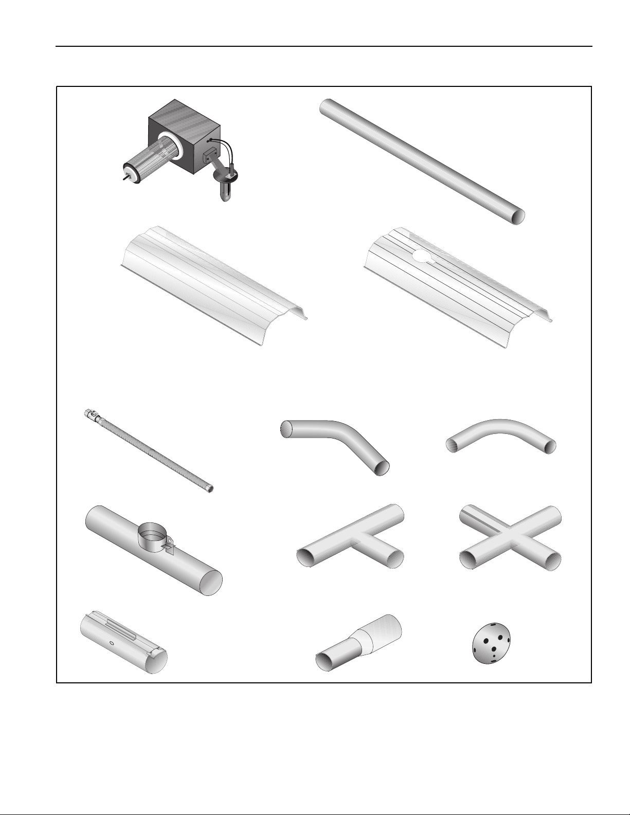
0133580D 4" Coated 90° Elbow
01336101 4" Aluminized 45° Elbow
0133610D 4" Coated 45° Elbow
91409300 16 Ga. Hot Rolled S teel 4" dia. 10' T ube
91409403 16 Ga. Non-heat treated Aluminized 4" dia. 10' T ube
91409408 16 Ga. Heat T reated Aluminized 4" dia. 10' Tube
91409420 16 Ga.Non-Heat Treated Aluminized 6" dia. 10' Tube
9141030D 16 Ga. Coated 4" dia. 10' Tube
E0009105 16 Ga. Heat T reated Aluminized 6" dia. 10' Tube
91418200 Aluminized Tube Adapter 6" dia. x 4" dia.
02722100 4" Cast Iron Adapter
91240010 6" Tube Hanger
Venting Accessories
01316000 Outside Air Supply Blower Mounting Kit
01324401 4" Outside Air Supply Takeoff
01326801 Outside Air Filter Housing
Common CRV-Series Components
Part No. Description
Combustion Chamber:
02722300-1P Hot Rolled Steel Combustion Cha mber
02722301-1P Heat-Treated Aluminized Steel Combustion Chamber
0272230D-1P Porcelain Coated Steel Combustion Chamber
02721200-1P Cast Iron Combustion Chamber
T ubing and Related Access ories
01312700 4" Plain Coupling
01312706 6" Plain Coupling
0131270I 4" Lined Coupli ng
01331900 4" Damper Coupling
E0009356 6" Damper Coupling
0133022D 4" Coated Tee
01330203 4" Aluminized T ee
01330204 6" Aluminized T ee
0133092D 4" Coated Cross
01330903 4" Aluminized Cross
01330904 6" Aluminized Cross
01330800 4” Tube Plug
01335801 4" Aluminized 90° Elbow
T0100320 6" Aluminized 90° Elbow
90707501 Air Supply Blower/Power Venter
91409601 4" Outside Air Flex Duct (Box of 8 - 8' secti ons)
90434501 Outside Air Pressure Switch
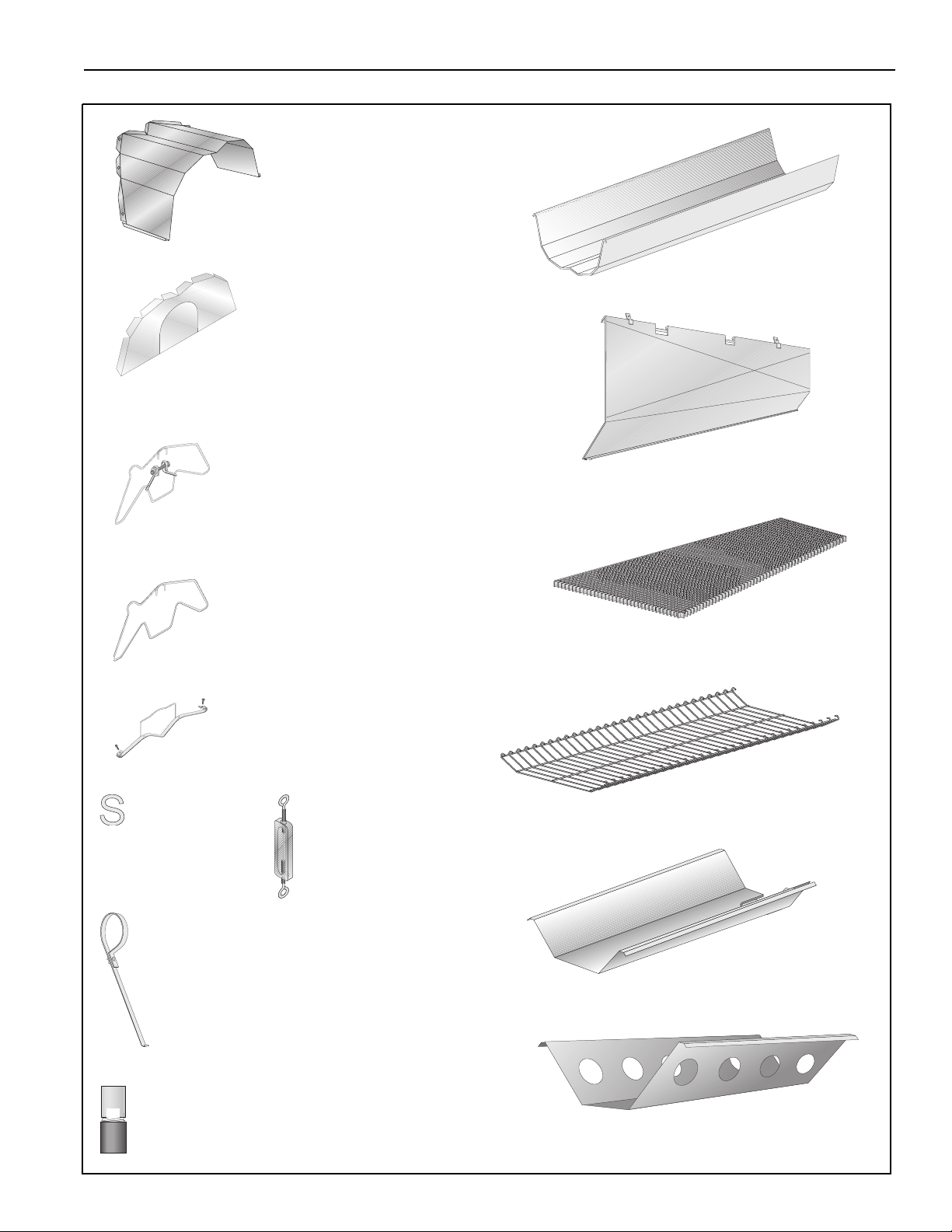
Reflectors and Related Accessories
01329910 Reflector Side Extension Support
03050010 Reflector Support Package (Tubing)
02712700 Reflector Side Extension, 2 Clips, 2 Screws
02716400 Reflector Support Package (Schedule 40 Pipe)
02750303 Aluminum Reflector
027503SS Stainless Steel Reflector
02750304 Aluminum Reflector with Hole
027503SH Stainless Steel Refle ctor with Hole
02750800 Aluminum Reflector End Cap
027508SS Stainless Steel Reflector End Cap
027508SH Stainless Steel Refle ctor End Cap with Hole
02750900 Reflector Joint
027509SS Stainless Steel Reflector Joint
027127SS Reflector Side Extension, Stainless Steel
03090100 Tube and Reflector Hanger
02790300 Tube and Reflector Hanger, Cast Iron
91907302 “S” Hook
91903201 Turnbuckle
91903300 Spring Hook
© 2004 Rober ts -Gordon
BEFORE INS TALLAT ION AND OPERAT ION OF HEATING EQUIPMENT, READ AND U NDERSTAND THE INSTALLATION, OPERATI ON AND SERVICE MANUA L.
APPLICATIONS , ENGINEERING AND DETA ILED GUIDA NCE ON SYS TEMS DESIGN, INSTALLAT ION AND PRODUCT P ERFORMANCE IS AVAILABLE UPON REQUEST . ROBERTS GORDON® PRODUCT S ARE TO BE
INSTALLED ONLY IN ACCORDANCE WITH LOCAL LAWS, CODES AND REGULATIONS, AND ONLY BY A CONT RACTOR QUALIFIED IN THE INSTALLA TION AND S ERVICE OF GAS-FI RED HEAT ING EQUIPMENT.
Page 3
ROBERTS GORDON® CRV-SERIES SUBM ITT AL SHEET
91903202 Turnbuckle with Eyebolt
02712100 Universal Shield Support
02751800 Universal Shield with Holes
02751801 Universal Shield
027518SS Universal Shield, Stainless Steel
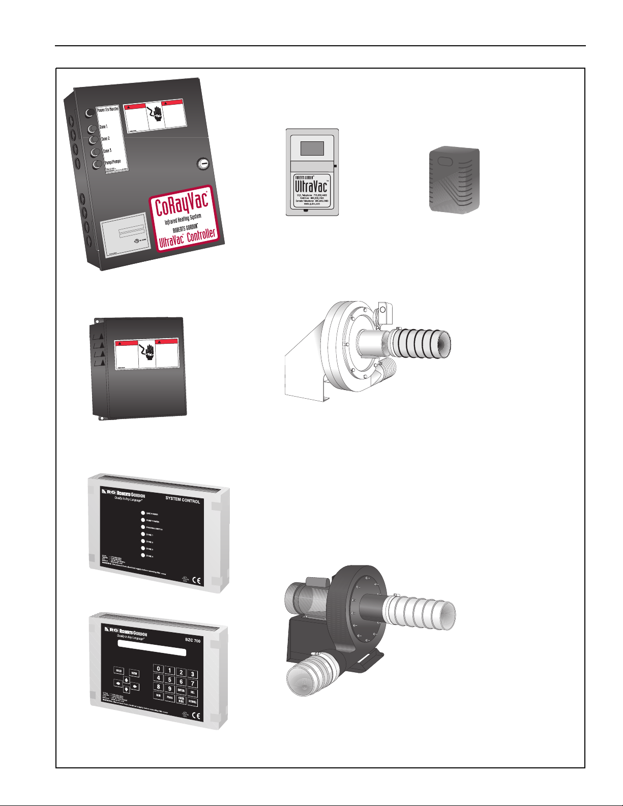
Control Packa ges and Acce ssories
BZC700
ROBERTS GORDON
10001500 Indoor Sensor*, ROBERTS GORDON
®
BZC 700 Controller
®
BZC 700 Controller
* One required pe r z one
10001501 Water Resistant Sensor
02770002 System Control
URVCCM
ROBERTS GORDON® ULTRAVAC™ Cen tral Controller
(with Modem Chip & So ftware ) Includes:
URVSC
ROBERTS GORDON
®
ULTRAVAC™ Controller
10080142 Modem Chip
10081501 Outdoor Sensor
10080410 PC Connection Cable Package
URVCCR
ROBERTS GORDON® ULTRAVAC™ Cen tral Controller
(with RS-485 Converter & Software) Includes:
URVSC ROBERTS GORDON® ULTRAVAC™ Controller
Thermostats
05023000 Load Relay Package
90417600 Transform er Rela y - SPST (12A)
90436300 Transform er Relay - DPDT (12A)
90423000 24V Low Voltage Thermostat (Marked 1-5)
90424300 Thermostat Guard
Deco Grille(1' x 8')
01363003 Bracket
01365901 End Piece
01326801 Reinforcement
01365903 Joint Piece
91406700 1' x 8' Protective Grille
Deco Grille(2' x 4')
01365900 Shield Frame
01370408 Reflector Side Extension 8" x 48"
01370412 Reflector Side Extension 12" x 48"
01370416 Reflector Side Extension 16" x 48"
91407000 Aluminum Grille 2' x 4'
10080430 RS-485 Converter with 9V Power Supply
10081501 Outdoor Sensor
10080410 PC Connection Cable Package
URVCCL
ROBERTS GORDON® ULTRAVAC™ Cen tral Controller
(with TCP/IP Communication Module & Software)
Includes:
URVSC ROBERTS GORDON® ULTRAVAC™ Controller
10080440 TCP/IP Comm unication Module
10081501 Outdoor Sensor
10080410 PC Connection Cable Package
®
URVSC Controller , ROBERTS GORDON
ULTRAVAC™ , 1 Pump 3
Zones (Satellite Control)
VFD75115 Variable Frequency Drive Assembly, 75HP, 115V Input
VFD75230 Variable Frequency Drive Assembly, 75HP, 230V Input
10080142 Modem, Plug-In Chip
10080410 Cable Package, PC connection
10080430 RS-485 Converter with 9V Power Supply
10080440 TCP/IP Communication Module
10081500 Sensor, Adjustable Indoor, Deg F, ROBERTS GORDON
ULTRAVAC™ Controller
Protective Grille
08050001 40" Protective Grille
08050002 Protective Grille End Cap
Shields
02750303 Barrier Shield
02751801 Universal Shield
027518SS Stainless Steel Universal Shield
02751800 Universal Shield with Holes
®
10081501 Sensor, Outdoor, ULTRAVAC™
10081502 Sensor, Adjustable Indoor, Deg C, ULTRAVAC™
© 2004 Roberts-Gordon
B EFORE INSTALLAT I ON AND OPERATION OF HEATI NG EQUIPM ENT, READ AND UNDERSTAND THE INSTALLATION, OPERATION AND SERVICE MANUAL.
A PPLICATIONS, ENGINEERING AND DE TAILED GUIDANCE ON SYSTEMS DES IGN, INSTAL LATION AND PRODUCT PERFORMANCE IS AVAILABLE UP ON REQUES T. ROBERTS GORDON® PRODUCTS ARE TO B E
INSTALLED ONLY IN ACCORDA NCE WITH LOCAL LA WS, CODES AND REGULATIONS, AND ONLY BY A CONTRACTOR QUALIFIED IN THE INSTA LLATION AND SERVICE OF GAS-FIRED HEATING EQUIPMENT.
Page 4
ROBERTS GORDON® CRV-SERIES SUBMITTAL SHEET
Pump Packages and Accessories
02719105
EP-100 Pump Package
02719100 EP-100 Pump
02724700 Accessory Package
02716305
EP-201 Pump Package
01312001 EP-201 Pump
01317805 Accessory Package
02712034
EP-203 Pump Package
01312002 EP-203 Pump
01317805 Accessory Package
02723014
EP-301 Pump Package 4"
02730101 EP-301 Pump Assembly
02730104 Accessory Package
02723016
EP-301 Pump Package 6"
02730101 EP-301 Pump Assembly
02730106 Accessory Package
Pump Accessories
90430600 Pressu re Switch
0 132700 1 Condens ate Check Valve Assemb ly
02718851 4" Drain Cap
02718852 6" Drain Cap
Starters
10050002 12V DC Starter for EP-201, 1PH
10050003 120V AC Starter for EP-201, 1PH
10050008 120VAC Starter for EP-301, 1PH
10050009 Contactor Package-230VAC Co il for EP-300, 2HP*
*Starter Package c an replace contactor package if pump trip ind ication is
desired when used in conjunction with the ROBERTS GORDON
®
BZC 700
controller.
© 2004 Rober ts -Gordon
BEFORE INS TALLAT ION AND OPERAT ION OF HEATING EQUIPMENT, READ AND U NDERSTAND THE INSTALLATION, OPERATI ON AND SERVICE MANUA L.
APPLICATIONS , ENGINEERING AND DETA ILED GUIDA NCE ON SYS TEMS DESIGN, INSTALLAT ION AND PRODUCT P ERFORMANCE IS AVAILABLE UPON REQUEST . ROBERTS GORDON® PRODUCT S ARE TO BE
INSTALLED ONLY IN ACCORDANCE WITH LOCAL LAWS, CODES AND REGULATIONS, AND ONLY BY A CONT RACTOR QUALIFIED IN THE INSTALLA TION AND S ERVICE OF GAS-FI RED HEAT ING EQUIPMENT.
Page 5
ROBERTS GORDON® CRV-SERIES SUBM ITT AL SHEET
GENERAL SPECIF ICATIONS
Material Specification
Reflectors
.024 Mill Finish
Steel Type 304).
Aluminium (Optional - 024 Stainless
Heater Specifications
Ignition
Suspension Specifications
Hang heater with materials with a minimum working
load of 75 lbs (33 kg).
Contro ls Specifications
Time switches, thermostats, etc. can be wired into
the electrical supply . Exter nal controls supplied as an
option.
Fully Automatic, Three-Try, Direct Spark, Electr o n ic
Ignition Control, 100% Safety Shut-Off.
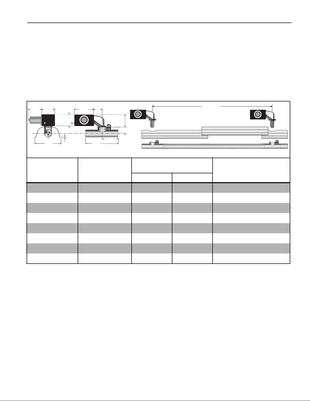
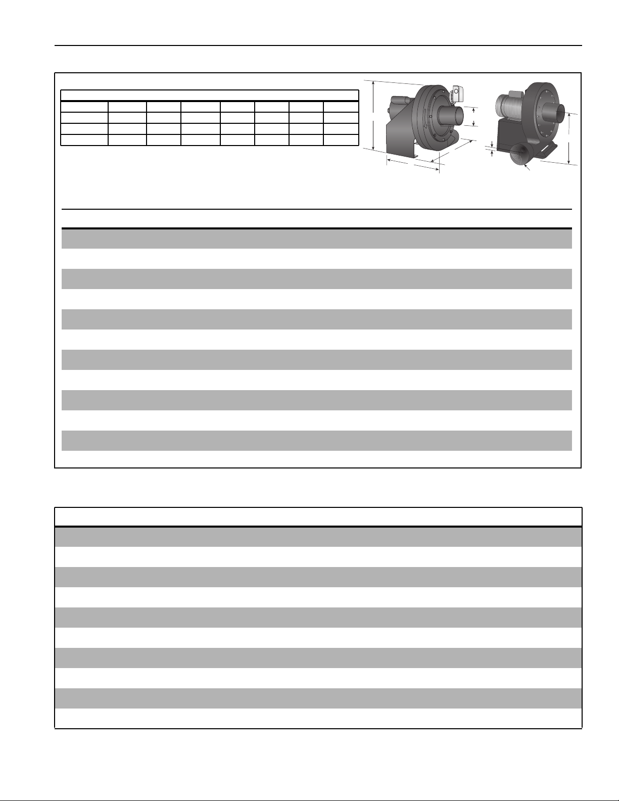
General Specific ations for CRV-Series heaters are as follows:
6 1/2"
9 1/2"
(24 cm)
(16 cm)
14 1/4"
(36 cm)
6 7/8"
(17 cm)
5/32"
(.4 cm)
10 3/4"
(27 cm)
(10 cm)
20"
(51 cm)
4"
7 5/8"
10"
(24.4 cm)
(19 cm)
3 1/2"
(9 cm)
Reflector
Heat Input Rate Length “A”
Length "A"
Recomm ended Minimum
Mounting Height*
Model (BTUH X1000) Minimum Maximum Spot Heating
CRV-B-2 (NG only) 20 10' (3 m) 20' (6.1 m) 8' (2.4 m)
CR V-B-4 40 12.5' (3.8 m) 25' (7.6 m) 8' (2.4 m)
CRV-B-6 60 20' (6.1 m ) 35' (10.7 m) 8' (2.4 m)
CRV-B-8 80 20' (6.1 m) 45' (13.7 m) 10' (3 m )
CRV-B-9 90 25' (7.6 m ) 50' (15.2 m) 10' (3 m)
CRV-B-10 100 30' (9.1 m) 60' (18.3 m ) 15' (4.5 m)
CRV-B-12A (NG only) 110 35' (10.7 m) 70' (21.3 m) 15' (4.5 m)
CRV-B-12 (LP only) 120 35' (10. 7 m) 70' (21.3 m ) 15' (4.5 m)
Pipe Connection
1/2" NPT
(36" Stainless Steel F lex Included with Burner)
Dimensions
Vent Connection Size: 4" (10 cm) or 6" (15 cm)
Gas Inlet Pressure
Natur al Gas: 4.5" w.c. Minimum 14.0" w.c. Maximum
LP Gas: 10.5" w.c. Minimum 14.0" w.c. Maximum
Electrical Rating
120V - 60 Hz., 0.3 Amp
Outside Air Connection Size: 4" (10 cm)
Refer to figure above for dimensional information.
Ignition System
© 2004 Roberts-Gordon
Fully Automatic, Three-Try, Direct Spark, Electronic
Ignition Control, 100% Shut-Off
B EFORE INSTALLAT I ON AND OPERATION OF HEATI NG EQUIPM ENT, READ AND UNDERSTAND THE INSTALLATION, OPERATION AND SERVICE MANUAL.
A PPLICATIONS, ENGINEERING AND DE TAILED GUIDANCE ON SYSTEMS DES IGN, INSTAL LATION AND PRODUCT PERFORMANCE IS AVAILABLE UP ON REQUES T. ROBERTS GORDON® PRODUCTS ARE TO B E
INSTALLED ONLY IN ACCORDA NCE WITH LOCAL LA WS, CODES AND REGULATIONS, AND ONLY BY A CONTRACTOR QUALIFIED IN THE INSTA LLATION AND SERVICE OF GAS-FIRED HEATING EQUIPMENT.
Page 6
ROBERTS GORDON® CRV-SERIES SUBMITTAL SHEET
Pump Specifications
Pum p Di m ensional Da ta (in .)
Model ABCDEFG
EP-100 17 14.5 21 3.75 10 4 4
EP-201/203 17.75 17 18.75 3.25 10 4.5 4.5
EP-301 25.6 24.8 22.7 4.8 15.2 6 6
A
C
G
D
B
Pump Specifications
Model EP-100 EP-201 EP-203 EP-301
Horsepower (Hp) 1/3 3/4 3/4 2*
Phase 1 1 3 1
Hertz (Hz) 60 60 60 60
Vol tage (V ) 115/230 115/230 230 230
Full Load Amp (Amps) 4.8/2.4 6.6/3.3 3.0 11.5
E
dia.
F
R.P.M. 3450 3450 3450 3450
Motor Frame 56 56 56 90
Mo tor Enclosure TENV TENV TEF C TEFC
Nois e Level @ 5' (DBA) - 70 70 Inlet/Outlet (In.) 4/4 4/4 4/4 6/6
Wei ght (lbs .) 62 112 112 170
* For starter, see National Electric Code (NEC) requirement for motors 1 hp or higher.
Air Supply Blower Specifications
Capacity 240 CFM @ 0.75" w. c.
P owe r (W) 167
Phase 1
Hertz (Hz) 60
Voltag e ( V) 120
Full Load Amp (Amps) 1.5
R.P.M. 3000
Motor Enclosure OPEN FC
Inlet/Outle t (In.) 5/5
Weight (lbs.) 10
© 2004 Rober ts -Gordon
BEFORE INS TALLAT ION AND OPERAT ION OF HEATING EQUIPMENT, READ AND U NDERSTAND THE INSTALLATION, OPERATI ON AND SERVICE MANUA L.
APPLICATIONS , ENGINEERING AND DETA ILED GUIDA NCE ON SYS TEMS DESIGN, INSTALLAT ION AND PRODUCT P ERFORMANCE IS AVAILABLE UPON REQUEST . ROBERTS GORDON® PRODUCT S ARE TO BE
INSTALLED ONLY IN ACCORDANCE WITH LOCAL LAWS, CODES AND REGULATIONS, AND ONLY BY A CONT RACTOR QUALIFIED IN THE INSTALLA TION AND S ERVICE OF GAS-FI RED HEAT ING EQUIPMENT.
Page 7
ROBERTS GORDON® CRV-SERIES SUBM ITT AL SHEET
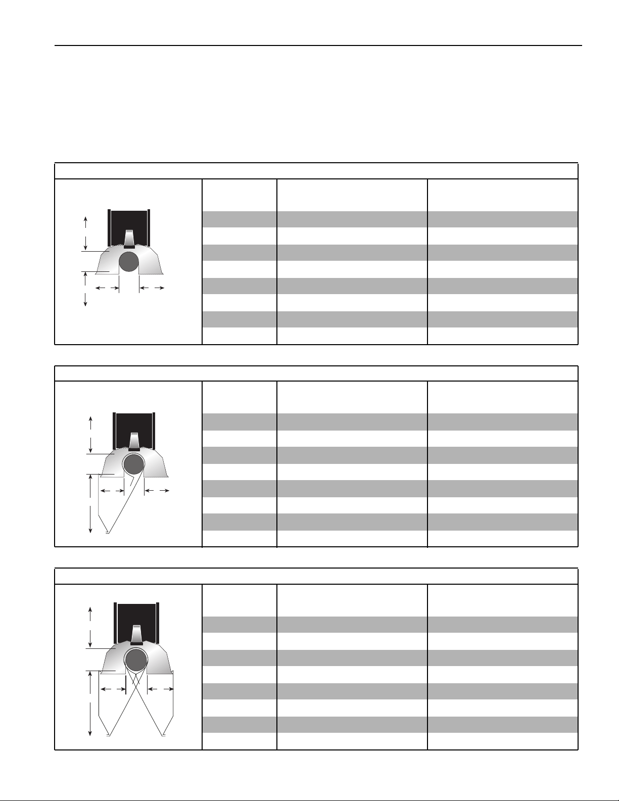
CLEARANCES TO COMBUSTIBLES
NOTE: 1. All dimensions are from the surfaces of al l t ubes, coupl ings , el bows, tees and c r osses.
2. Clearances B, C and D can be reduced by 50% after 25' (7.5 m) of tubing downstream from
where the combusti on chamber and the tube connect.
3. “-” indicates an unapproved applicati on. R oberts-Gor don prohibits the installation of this
he ate r for al l unappr oved ap pl i cat ions.
* Protective Grille clearances are the same as Standard Reflector.
Standard Reflector*
Model ABCDABCD
CRV-B-2 4 20 48 20 11 51 122 51
A
B
C
D
CRV-B-4 4 20 48 20 11 51 122 51
CRV-B-6 4 20 48 20 11 51 122 51
CRV-B-8 4 20 48 20 11 51 122 51
CRV-B-9 4 36 60 36 11 92 153 92
CRV-B-10 4 36 60 36 11 92 153 92
CRV-B-12 4 36 60 36 11 92 153 92
CRV-B-12A 4 36 60 36 11 92 153 92
(inches) (c entimeters)
.
One Side Reflector
A
B
C
Two Side Reflectors
A
B
C
(inches) (c entimeters)
Model ABCDABCD
CRV-B-2 4 12 56 20 11 31 143 51
CRV-B-4 4 12 56 20 11 31 143 51
CRV-B-6 4 12 56 20 11 31 143 51
CRV-B-8 4 12 56 20 11 31 143 51
D
CRV-B-9 4 12 60 42 11 31 153 107
CRV-B-10 4 12 60 42 11 31 153 107
CRV-B-12 4 12 60 42 11 31 153 107
CRV-B-12A 4 12 60 42 11 31 153 107
(inches) (c entimeters)
Model ABCDABCD
CRV-B-2 4 12 56 12 11 31 143 31
CRV-B-4 4 12 56 12 11 31 143 31
CRV-B-6 4 12 56 12 11 31 143 31
CRV-B-8 4 12 56 12 11 31 143 31
D
CRV-B-9 4 12 60 12 11 31 153 31
CRV-B-10 4 12 60 12 11 31 153 31
CRV-B-12 4 12 60 12 11 31 153 31
CRV-B-12A 4 12 60 12 11 31 153 31
© 2004 Roberts-Gordon
B EFORE INSTALLAT I ON AND OPERATION OF HEATI NG EQUIPM ENT, READ AND UNDERSTAND THE INSTALLATION, OPERATION AND SERVICE MANUAL.
A PPLICATIONS, ENGINEERING AND DE TAILED GUIDANCE ON SYSTEMS DES IGN, INSTAL LATION AND PRODUCT PERFORMANCE IS AVAILABLE UP ON REQUES T. ROBERTS GORDON® PRODUCTS ARE TO B E
INSTALLED ONLY IN ACCORDA NCE WITH LOCAL LA WS, CODES AND REGULATIONS, AND ONLY BY A CONTRACTOR QUALIFIED IN THE INSTA LLATION AND SERVICE OF GAS-FIRED HEATING EQUIPMENT.
Page 8
ROBERTS GORDON® CRV-SERIES SUBMITTAL SHEET
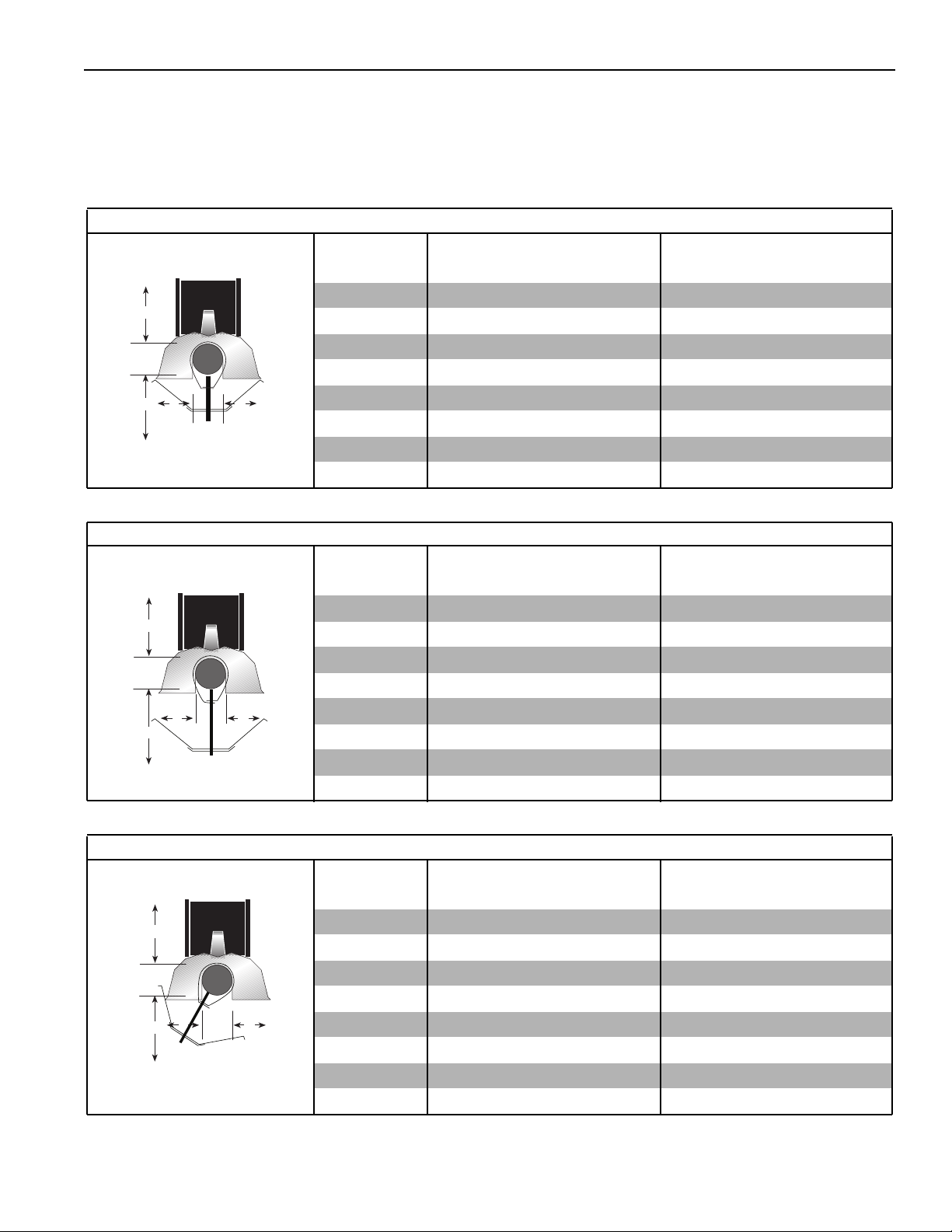
NOTE: 1. Al l dimensions are from the surfaces of all tubes, couplings, elbows, tees and crosses.
2. Cl ear ances B, C and D can be reduced by 50% af ter 25' (7.5 m) of tubi ng downstream from
where the combustion chamber and the tube connect.
3. “- ” indi c a tes an unap pr oved ap pli c ati o n. Robe rts - Gor d on pr oh ib i ts th e in s tal l at io n of t his h ea t er
fo r a l l un app r ov e d app l ica t i on s.
Universal Shield, Position 1
(inches) ( centimeters)
Model ABCDABCD
A
B
C
D
Universal Shield, Position 2
A
B
C
D
CRV-B-2 4 12 12 12 11 31 31 31
CRV-B-4 4 12 12 12 11 31 31 31
CRV-B-6 4 12 12 12 11 31 31 31
CRV-B-8 4 12 12 12 11 31 31 31
CRV-B-9 8 18 24 18 21 46 61 46
CRV-B-10 8 18241821466146
CRV-B-12 8 18 24 18 21 46 61 46
CRV-B-12A 818241821466146
(inches) ( centimeters)
Model ABCDABCD
CRV-B-2 4 24 48 24 11 61 122 61
CRV-B-4 4 24 48 24 11 61 122 61
CRV-B-6 4 24 48 24 11 61 122 61
CRV-B-8 4 24 48 24 11 61 122 61
CRV-B-9 4 36 48 36 11 92 122 92
CRV-B-10 4 36 48 36 11 92 122 92
CRV-B-12 4 36 48 36 11 92 122 92
CRV-B-12A 4 36 48 36 11 92 122 92
Universal Shield, Position 3
A
B
C
© 2004 Rober ts -Gordon
D
BEFORE INS TALLAT ION AND OPERAT ION OF HEATING EQUIPMENT, READ AND U NDERSTAND THE INSTALLATION, OPERATI ON AND SERVICE MANUA L.
APPLICATIONS , ENGINEERING AND DETA ILED GUIDA NCE ON SYS TEMS DESIGN, INSTALLAT ION AND PRODUCT P ERFORMANCE IS AVAILABLE UPON REQUEST . ROBERTS GORDON® PRODUCT S ARE TO BE
INSTALLED ONLY IN ACCORDANCE WITH LOCAL LAWS, CODES AND REGULATIONS, AND ONLY BY A CONT RACTOR QUALIFIED IN THE INSTALLA TION AND S ERVICE OF GAS-FI RED HEAT ING EQUIPMENT.
(inches) ( centimeters)
Model ABCDABCD
CRV-B-2 4 12 56 30 11 31 143 77
CRV-B-4 4 12 56 30 11 31 143 77
CRV-B-6 4 12 56 30 11 31 143 77
CRV-B-8 4 12 56 30 11 31 143 77
CRV-B-9 8 12 60 42 21 31 153 107
CRV-B-10 8 12 60 42 21 31 153 107
CRV-B-12 8 12 60 42 21 31 153 107
CRV-B-12A 8 12 60 42 21 31 153 107
Page 9
ROBERTS GORDON® CRV-SERIES SUBM ITT AL SHEET
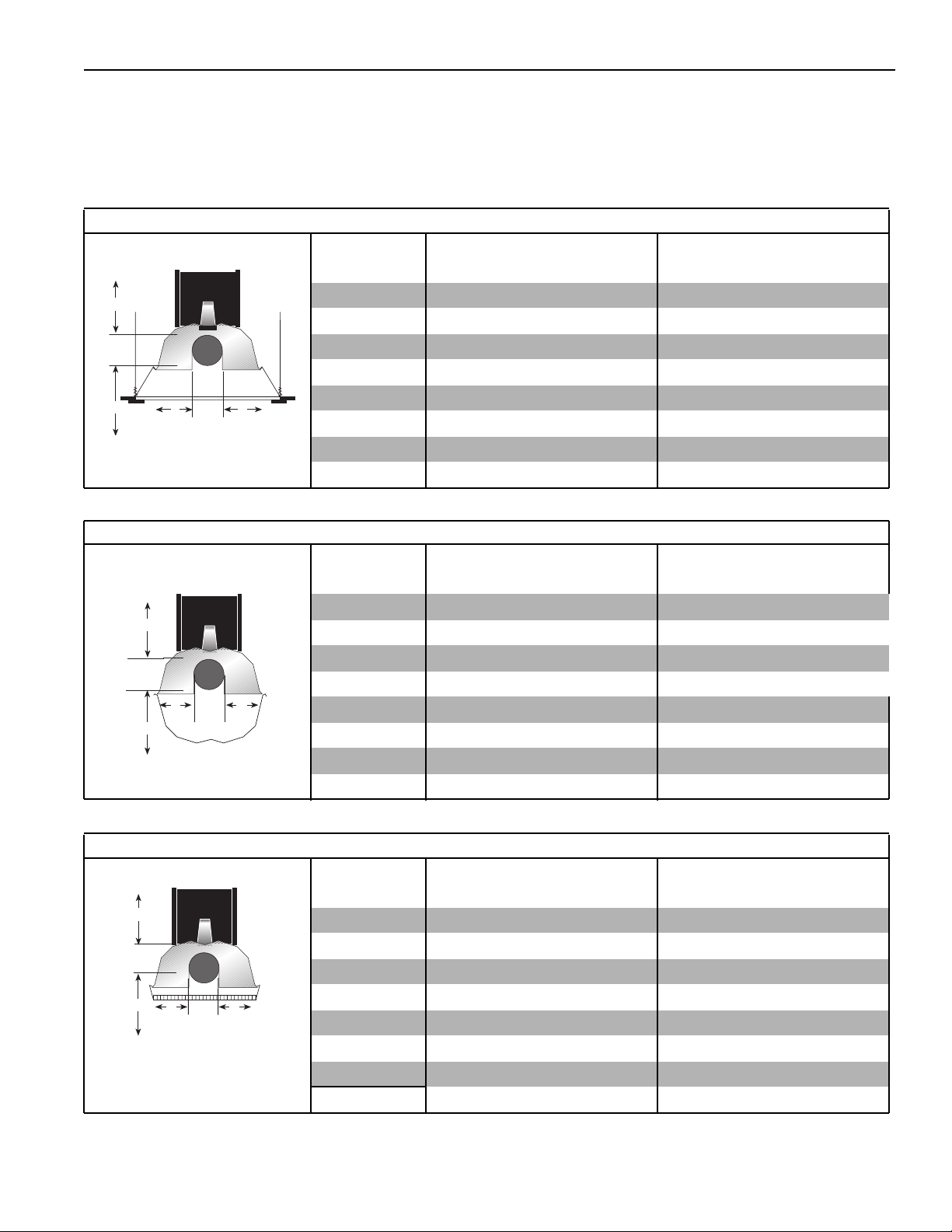
NOTE: 1. All di mensions are from the surfaces of all tubes, couplings, elbows, tees and crosses.
2. Clearances B, C and D can be r educed by 50% after 25' (7.5 m) of tubing downstream from
where the combustion chamber and the tube connect.
3. “ - ” indi cates an unapproved appl icat ion. Roberts -Gordon pr ohibits the installati on of thi s heater
fo r all unapproved applicat ions.
2-Foot Deco Grille
(inches) (c entimeters)
Model ABCDABCD
A
C
B
Barrier Shield
A
B
C
CRV-B-2 4 12 48 12 11 31 122 31
CRV-B-4 4 12 48 12 11 31 122 31
CRV-B-6 4 12 48 12 11 31 122 31
CRV-B-8 4 12 48 12 11 31 122 31
D
CRV-B-9 4 18 56 18 11 46 143 46
CRV-B-10 4 18 56 18 11 46 143 46
CRV-B-12 4 18 56 18 11 46 143 46
CRV-B-12A 4 18 56 18 11 46 143 46
(inches) (c entimeters)
Model ABCDABCD
CRV-B-2 4 12 12 12 11 31 31 31
CRV-B-4 4 12 12 12 11 31 31 31
CRV-B-6 4 12 12 12 11 31 31 31
CRV-B-8 4 12 12 12 11 31 31 31
D
CRV-B-9 - - - - - - - -
CRV-B-10-------CRV-B-12 - - - - - - - -
CRV-B-12A--------
1-Foot Deco Grille
A
C
B
D
© 2004 Roberts-Gordon
(inches) (c entimeters)
Model ABCDABCD
CRV-B-2 4 12 48 12 11 31 122 31
CRV-B-4 4 12 48 12 11 31 122 31
CRV-B-6 4 12 48 12 11 31 122 31
CRV-B-8 4 12 48 12 11 31 122 31
CRV-B-9 4 18 56 18 11 46 143 46
CRV-B-10 4 18 56 18 11 46 143 46
CRV-B-12 4 18 56 18 11 46 143 46
CRV-B-12A 4 18 56 18 11 46 143 46
B EFORE INSTALLAT I ON AND OPERATION OF HEATI NG EQUIPM ENT, READ AND UNDERSTAND THE INSTALLATION, OPERATION AND SERVICE MANUAL.
A PPLICATIONS, ENGINEERING AND DE TAILED GUIDANCE ON SYSTEMS DES IGN, INSTAL LATION AND PRODUCT PERFORMANCE IS AVAILABLE UP ON REQUES T. ROBERTS GORDON® PRODUCTS ARE TO B E
INSTALLED ONLY IN ACCORDA NCE WITH LOCAL LA WS, CODES AND REGULATIONS, AND ONLY BY A CONTRACTOR QUALIFIED IN THE INSTA LLATION AND SERVICE OF GAS-FIRED HEATING EQUIPMENT.
Page 10
ROBERTS GORDON® CRV-SERIES SUBMITTAL SHEET
CRV-SER IES ASSEMBLY O VE RVIEW
Major Component Descriptions
Burner
Reflec tor
(Aluminum or
Stainless Steel)
Alternate overlap as
shown on overview.
Minimum overlap is 7"
(18 cm).
Tube
Hot Rolled, Heat Treated or
Coated Aluminized Tube
supplied in 10' (3 m) lengths.
Reflector with Hole
(Aluminum or
Stainless Steel)
Alternate overlap as
shown on overview.
Minimum overlap is 7"
(18 cm).
Flex Gas Line
with shut-off cock
Combustion Chamber
Coupling Assembly
with Lock
45° Elbow
Tee
Tu be Ad a p t e r
90° Elbow
Cross
End Vent
© 2004 Rober ts -Gordon
BEFORE INS TALLAT ION AND OPERAT ION OF HEATING EQUIPMENT, READ AND U NDERSTAND THE INSTALLATION, OPERATI ON AND SERVICE MANUA L.
APPLICATIONS , ENGINEERING AND DETA ILED GUIDA NCE ON SYS TEMS DESIGN, INSTALLAT ION AND PRODUCT P ERFORMANCE IS AVAILABLE UPON REQUEST . ROBERTS GORDON® PRODUCT S ARE TO BE
INSTALLED ONLY IN ACCORDANCE WITH LOCAL LAWS, CODES AND REGULATIONS, AND ONLY BY A CONT RACTOR QUALIFIED IN THE INSTALLA TION AND S ERVICE OF GAS-FI RED HEAT ING EQUIPMENT.
Page 11
ROBERTS GORDON® CRV-SERIES SUBM ITT AL SHEET
Major Component Descriptions (Continued)
Reflector Joint
Reflector End Cap
(Aluminum or Stainless
Steel)
Remove center section to
accommodate heat
ex cha nger tube when
necessary.
Tube and Reflector Hanger
with Clamp Package
Position this hanger no more
than 4" (10 cm) away from
the burner.
Tube and Reflector Hanger
Suspend system from these
hangers.
Reflector Support Strap &
Wire Form
Barrier Shield
Reflector Side Extension
Deco Grille
“S” Hook
Reflector Side
Extension Bracket
Condensate Valve
Assembly
© 2004 Roberts-Gordon
Turnbuckle
Prote c tive Grille
Universal Shield
Universal Shield with Holes
B EFORE INSTALLAT I ON AND OPERATION OF HEATI NG EQUIPM ENT, READ AND UNDERSTAND THE INSTALLATION, OPERATION AND SERVICE MANUAL.
A PPLICATIONS, ENGINEERING AND DE TAILED GUIDANCE ON SYSTEMS DES IGN, INSTAL LATION AND PRODUCT PERFORMANCE IS AVAILABLE UP ON REQUES T. ROBERTS GORDON® PRODUCTS ARE TO B E
INSTALLED ONLY IN ACCORDA NCE WITH LOCAL LA WS, CODES AND REGULATIONS, AND ONLY BY A CONTRACTOR QUALIFIED IN THE INSTA LLATION AND SERVICE OF GAS-FIRED HEATING EQUIPMENT.
Page 12
ROBERTS GORDON® CRV-SERIES SUBMITTAL SHEET
Major Component Descriptions (Continued)
R
E
G
N
A
D
e
u
q
i
r
t
c
e
R
E
G
N
A
D
d
r
a
z
a
H
k
c
o
h
S
l
a
c
i
r
t
c
e
l
E
l
a
c
i
r
t
c
e
l
e
t
c
e
n
n
o
c
.
s
g
i
n
i
D
c
i
v
r
e
s
e
r
o
f
e
b
r
e
w
o
p
e
b
t
s
u
m
e
c
n
a
i
l
p
p
a
s
y
i
l
r
h
e
T
p
o
r
p
a
o
t
d
e
t
c
e
e
c
r
n
u
n
o
o
s
c
l
a
c
i
r
t
c
e
l
e
d
e
d
n
u
o
r
g
e
s
e
h
t
w
o
l
l
o
f
o
t
e
r
u
l
i
t
l
a
u
F
s
e
r
n
a
c
s
n
o
i
t
c
c
u
o
r
t
h
s
s
n
l
i
a
c
i
r
t
c
e
l
e
r
o
h
t
a
e
d
n
i
.
c
n
i
-
g
r
.
w
w
w
©
®
N
O
D
r
R
O
G
S
T
lle
R
E
B
o
O
R
r
t
n
o
C
c
a
V
a
r
lt
U
:
r
e
b
:
m
e
u
c
N
è
i
t
r
P
a
a
l
P
e
d
o
r
é
m
u
N
u
N
l
a
i
r
e
S
S
e
d
.
o
N
s
g
n
i
t
a
R
s
t
r
e
b
o
R
x
o
B
.
O
.
P
,
o
l
a
f
f
u
B
o
h
p
e
l
e
T
1
7
:
x
a
F
e
r
F
l
l
o
T
r
.
w
w
w
©
:
r
e
b
m
:
e
i
r
é
0
2
1
t
u
p
n
I
:
n
o
d
r
o
G
4
4
0
0
4
2
4
1
Y
N
2
5
8
.
6
1
7
:
e
n
4
5
8
0
.
2
5
8
.
6
.
8
2
8
.
0
0
8
:
e
m
o
c
.
c
n
i
g
t
u
p
t
u
O
A
5
2
,
C
A
V
o
d
r
o
G
-
s
t
r
e
b
t
o
e
e
R
r
t
S
n
i
a
M
6
7
0
1
t
i
n
a
t
U
n
O
,
4
y
4
b
0
s
m
i
r
G
0
0
4
a
4
d
.
a
n
a
0
C
9
:
e
n
o
h
p
e
l
e
5
T
4
9
.
5
0
0
5
9
4
:
7
x
a
F
in U.S.A/Imprimé aux Etats-Unis P/N 91008005 Rev B
Printed
)
l
a
t
o
t
8
(
A
3
,
C
A
V
0
2
1
s
n
t
s
e
W
Y
G
R
E
6
N
T
R
E
N
1
E
D
E
M
M
S
P
I
3
O
U
L
L
Q
C
E
o
N
i
T
E
r
N
E
M
E
G
B
A
S
N
8
A
5
M
3
0
4
5
.
5
4
9
.
5
1
1
5
0
.
l
É
c
o
h
C
e
d
r
e
g
n
a
D
t
n
a
r
u
o
c
e
l
r
e
h
c
n
a
r
b
é
e
t
D
u
o
t
t
n
a
v
a
e
u
q
i
r
t
c
e
l
é
.
n
o
i
s
i
v
é
r
e
r
t
ê
t
i
o
d
l
i
e
r
a
p
e
p
d
a
t
e
e
c
r
C
u
o
s
e
n
u
à
r
e
t
c
.
e
e
n
r
r
n
e
o
t
c
á
e
s
i
m
c
e
v
a
t
n
a
r
u
o
c
.
k
o
c
s
e
c
e
r
v
i
u
s
a
e
l
d
r
e
e
t
n
î
u
a
a
r
t
F
n
e
t
u
e
p
s
n
.
o
i
s
t
e
c
u
u
r
q
t
i
r
s
t
n
c
i
e
l
é
c
o
h
c
s
e
l
u
o
t
r
o
1
0
0
m
8
0
0
1
9
.
m
N
/
P
A
.
S
.
U
e
h
t
n
i
d
e
t
n
i
r
P
s
i
n
U
s
t
a
t
E
x
u
a
é
m
i
r
p
m
I
ROBERTS GORDON®
ULTRAVAC™
Adjustable Indoor Sen s or
ROBERTS GORDON
BZC Indoor Sensor
®
ROBERTS GORDON
®
ULTRAVAC™ Cont rolle r
D
d
r
a
z
a
H
k
c
o
h
S
l
a
c
i
r
t
c
e
l
E
l
a
c
i
r
t
c
e
l
e
t
c
e
n
n
o
c
s
i
D
.
g
n
i
c
i
v
r
e
s
e
r
o
f
e
b
r
e
w
o
p
e
b
t
s
u
m
e
c
n
a
i
l
p
p
a
s
i
h
T
y
l
r
e
p
o
r
p
a
o
t
d
e
t
c
e
n
n
o
c
.
e
c
r
u
o
s
l
a
c
i
r
t
c
e
l
e
d
e
d
n
u
o
r
g
e
s
e
h
t
w
o
l
l
o
f
o
t
e
r
u
l
i
a
F
t
l
u
s
e
r
n
a
c
s
n
o
i
t
c
u
r
t
s
n
i
.
k
c
o
h
s
l
a
c
i
r
t
c
e
l
e
r
o
h
t
a
e
d
n
i
n
i
r
P
i
r
p
m
I
m
o
c
.
c
n
i
g
r
.
w
w
w
©
ROBERTS GORDON
e
u
q
i
r
t
c
e
l
É
c
o
h
C
e
d
r
e
g
n
a
D
t
n
a
r
u
o
c
e
l
r
e
h
c
n
a
r
b
é
D
e
t
u
o
t
t
n
a
v
a
e
u
q
i
r
t
c
e
l
é
.
n
o
i
s
i
v
é
r
e
r
t
ê
t
i
o
d
l
i
e
r
a
p
p
a
t
e
C
e
d
e
c
r
u
o
s
e
n
u
à
r
e
t
c
e
n
n
o
c
.
e
r
r
e
t
á
e
s
i
m
c
e
v
a
t
n
a
r
u
o
c
s
e
c
e
r
v
i
u
s
e
d
e
t
u
a
F
a
l
r
e
n
î
a
r
t
n
e
t
u
e
p
s
n
o
i
t
c
u
r
t
s
n
i
.
s
e
u
q
i
r
t
c
e
l
é
c
o
h
c
s
e
l
u
o
t
r
o
m
A
.
S
.
1
U
0
e
0
h
8
t
0
n
0
i
1
d
9
e
t
N
/
P
s
i
n
U
s
t
a
t
E
x
u
a
é
m
®
R
E
G
N
A
D
R
E
G
N
A
ULTRAVAC™
Variable Fr equency Drive
EP-100 Pu mp Package - 4" dia.
For more information, refer to the EP-100 Installation,
Operation and Service Manual (P/N 127201NA).
EP-201 Pu mp Package - 4" dia.
For more information, refer to the EP-201/203
Installation, Operation and Service Manual
(P/N 127200NA).
EP-203 Pu mp Package - 4" dia.
For more information, refer to the EP-201/203
Installation, Operation and Service Manual
(P/N 127200NA).
System Control
ROBERTS GORDON
BZC 700 Controller
© 2004 Rober ts -Gordon
EP-301 Pump Package - 4" dia.
EP-301 Pump Package - 6" dia.
®
For more inf ormation, refer to the EP-301 Installation,
Operation and Service Manual (P/N 127202NA).
BEFORE INS TALLAT ION AND OPERAT ION OF HEATING EQUIPMENT, READ AND U NDERSTAND THE INSTALLATION, OPERATI ON AND SERVICE MANUA L.
APPLICATIONS , ENGINEERING AND DETA ILED GUIDA NCE ON SYS TEMS DESIGN, INSTALLAT ION AND PRODUCT P ERFORMANCE IS AVAILABLE UPON REQUEST . ROBERTS GORDON® PRODUCT S ARE TO BE
INSTALLED ONLY IN ACCORDANCE WITH LOCAL LAWS, CODES AND REGULATIONS, AND ONLY BY A CONT RACTOR QUALIFIED IN THE INSTALLA TION AND S ERVICE OF GAS-FI RED HEAT ING EQUIPMENT.
Page 13

ROBERTS GORDON® CRV-SERIES SUBM ITT AL SHEET
CRV-Series Assembly Overview
Controller
ULTRAVAC
®
BZC Controller
®
System Control
or ROBERTS GORDON
ROBERTS GORDON
Exhaust
to Outside
Relay*
Pressure Switch
Pump
Boot
Flexible
Reflector
Reflector
with Hole
Coupling
Tube &
Reflector
Tube
Hanger
U-Clips
S
Support
Reflector
requires zone sensors and additional
®
ULTRAVAC
®
BZC Controllers require zone sensors. System Control requires
®
© 2004 Roberts-Gordon
End
Vent
Chamber
Combustion
Zone 1 Sensor or Thermostat**
appropriate controller Installation, Operation and Service Manual for details.
* May not be needed with certain pumps and controllers. Refer to wiring diagram in the
**ROBERTS GORDON
control equipment. See the appropriate controller installation manual for details.
thermostats. ROBERTS GORDON
Burner
End Cap
Reflector
B EFORE INSTALLAT I ON AND OPERATION OF HEATI NG EQUIPM ENT, READ AND UNDERSTAND THE INSTALLATION, OPERATION AND SERVICE MANUAL.
A PPLICATIONS, ENGINEERING AND DE TAILED GUIDANCE ON SYSTEMS DES IGN, INSTAL LATION AND PRODUCT PERFORMANCE IS AVAILABLE UP ON REQUES T. ROBERTS GORDON® PRODUCTS ARE TO B E
INSTALLED ONLY IN ACCORDA NCE WITH LOCAL LA WS, CODES AND REGULATIONS, AND ONLY BY A CONTRACTOR QUALIFIED IN THE INSTA LLATION AND SERVICE OF GAS-FIRED HEATING EQUIPMENT.
Page 14

ROBERTS GORDON® CRV-SERIES SUBMITTAL SHEET
HEATER I NSTALLATION
Critical Hanger Placement
Typical Suspension Details
Beam Clamp
Rod (3/8")
24" min.
(61 cm)
"X" (see table)
Chain size
3/16" minimum
Turnbuckle
Locknut
(Typical)
Anchor
Screw Hook
(3/8")
S Hook
Concrete Beam
Wood Beam
Locknut
Washers
Side View Towards Pump
Description Part Number
Turnbuckle 91903201
S-Hook 91907302
Tube/Ref lector Hanger 03090100
7'6" (2.3 m)
Turnbuckle
Hanger
Reflector
Front View
Run Length Typical Expa nsion Min imum “X ” Lengt h
50' (1 5 m) ±1" (3 cm) 1 2" (30 cm)
100' ( 31 m) ±2 " ( 5 cm) 24" (61 cm)
150' ( 46 m) ±3 " ( 8 cm) 36" (91 cm)
200' ( 61 m) ±4 " (1 0 cm) 46" (122 cm)
250' ( 76 m) ±5 " (1 3 cm) 57" (145 cm)
© 2004 Rober ts -Gordon
BEFORE INS TALLAT ION AND OPERAT ION OF HEATING EQUIPMENT, READ AND U NDERSTAND THE INSTALLATION, OPERATI ON AND SERVICE MANUA L.
APPLICATIONS , ENGINEERING AND DETA ILED GUIDA NCE ON SYS TEMS DESIGN, INSTALLAT ION AND PRODUCT P ERFORMANCE IS AVAILABLE UPON REQUEST . ROBERTS GORDON® PRODUCT S ARE TO BE
INSTALLED ONLY IN ACCORDANCE WITH LOCAL LAWS, CODES AND REGULATIONS, AND ONLY BY A CONT RACTOR QUALIFIED IN THE INSTALLA TION AND S ERVICE OF GAS-FI RED HEAT ING EQUIPMENT.
Page 15

ROBERTS GORDON® CRV-SERIES SUBM ITT AL SHEET
Tube Installation
Combustion
Chamber
NOTE: Tubing requires a downward slope of
1/2" (13 mm) per 20' (6 m) away from
burner. Tailpipe Tubing requires a
downward slope of 1" (26 mm) per
20' (6 m) away from burner.
End View
Weld
Seam
Bottom
of Tube
7' 6"
(229 cm)
Description Part Number
Tube 91409XXX
Turnbuckle 91903201
Tube/Ref lector Hanger 03090100
Coupling and Tube Assembly
Close c oupli ng with tab
A
Open
Tab
Tube
10'
maximum
(3 m)
B
Hanger
Turnbuckles
Combustion
Chamber
Start slide bar/coupling lock
onto coupli ng
Slide Bar/Coupling Lock
Wide end
Coupling
3" (8 cm) to
4" (10 cm)
Closed
Insert tubes into coupling
C
Tube
© 2004 Roberts-Gordon
Ti ght en coupli ng t o join tubes
D
Slide Bar/Coupling Lock
Orient coupling so that
the impact block is in the
2:00 or 10:00 oclock
positions
Tube
B EFORE INSTALLAT I ON AND OPERATION OF HEATI NG EQUIPM ENT, READ AND UNDERSTAND THE INSTALLATION, OPERATION AND SERVICE MANUAL.
A PPLICATIONS, ENGINEERING AND DE TAILED GUIDANCE ON SYSTEMS DES IGN, INSTAL LATION AND PRODUCT PERFORMANCE IS AVAILABLE UP ON REQUES T. ROBERTS GORDON® PRODUCTS ARE TO B E
INSTALLED ONLY IN ACCORDA NCE WITH LOCAL LA WS, CODES AND REGULATIONS, AND ONLY BY A CONTRACTOR QUALIFIED IN THE INSTA LLATION AND SERVICE OF GAS-FIRED HEATING EQUIPMENT.
Description Part Number
Coupling 01329600
Slide Bar /Coup l ing Lock 01329700
Tube 91409XXX
Tube
Coupling
Page 16

ROBERTS GORDON® CRV-SERIES SUBMITTAL SHEET
Coupling and Tube Assembly (Continued)
Tighten Slide B ar as show n below.
Drive Slide Bar until tight.
End of Slide Bar should be
within tolerance listed below.
± 2" (5 cm)
Correct Slide Bar
dimensions
Repeat A - D until all tubes are assem bled.
NOTE: If Coupling is not tight, loss of vacuum can occur.
ELBOW PACKAGE CONFIGURATIO N
Elbow Installatio n
Tube
Incorrect Slide Bar
position
Description Part Number
Elbow Package 02718702
90° Elbow 01335801
Coupling 01312700
Reflector End Cap 02750800
Reflector Joint Piece 02750900
U-Cl ip Package 91107720
Elbow Installatio n (continued)
Coupling
90° Elbow
Tube
Coupling
© 2004 Rober ts -Gordon
BEFORE INS TALLAT ION AND OPERAT ION OF HEATING EQUIPMENT, READ AND U NDERSTAND THE INSTALLATION, OPERATI ON AND SERVICE MANUA L.
APPLICATIONS , ENGINEERING AND DETA ILED GUIDA NCE ON SYS TEMS DESIGN, INSTALLAT ION AND PRODUCT P ERFORMANCE IS AVAILABLE UPON REQUEST . ROBERTS GORDON® PRODUCT S ARE TO BE
INSTALLED ONLY IN ACCORDANCE WITH LOCAL LAWS, CODES AND REGULATIONS, AND ONLY BY A CONT RACTOR QUALIFIED IN THE INSTALLA TION AND S ERVICE OF GAS-FI RED HEAT ING EQUIPMENT.
Page 17

ROBERTS GORDON® CRV-SERIES SUBM ITT AL SHEET
REFLECTOR INSTALLATION
Reflector Inst a llation with Hole
Reflector
with Hole
Slide Reflector
with hole
through hanger.
Unhook combustion
chamber from chain
and insert through hole.
Reconnect chain.
Hanger
Tube
Descript ion Par t Numbe r
Tube/ R e fl ec to r Ha ng er 03 09 01 00
Tube 91409XX X
Reflector with Hole 02750304
Reflector Inst a llation
Wire Form
Reflector
Reflector Support
Strap
Desc ription P art Nu mber
Reflect or Support Package 03050010
U-Clip Package 91107720
Reflector End Cap 027508XX
Sheet Metal
Screw
Tube
Combustion
Chamber
U-Clip
(2 clips per
alternate overlaps
per side)
© 2004 Roberts-Gordon
B EFORE INSTALLAT I ON AND OPERATION OF HEATI NG EQUIPM ENT, READ AND UNDERSTAND THE INSTALLATION, OPERATION AND SERVICE MANUAL.
A PPLICATIONS, ENGINEERING AND DE TAILED GUIDANCE ON SYSTEMS DES IGN, INSTAL LATION AND PRODUCT PERFORMANCE IS AVAILABLE UP ON REQUES T. ROBERTS GORDON® PRODUCTS ARE TO B E
INSTALLED ONLY IN ACCORDA NCE WITH LOCAL LA WS, CODES AND REGULATIONS, AND ONLY BY A CONTRACTOR QUALIFIED IN THE INSTA LLATION AND SERVICE OF GAS-FIRED HEATING EQUIPMENT.
Page 18

ROBERTS GORDON® CRV-SERIES SUBMITTAL SHEET
Reflector, U-Clip and Reflector Support Installation
The pictorial drawings of the heater construction in
this Section are schematic only and provide a general guideline of where hangers, reflector supports
and U-clips are to be installed.
To ensure proper expansion and contraction movement of the reflectors, a combination of U-clips and
reflector supports are used. The positioning of reflec-
1. The first reflector after the burner must be affixed in
the middle of the reflector with a reflector support and
tight screws.
Reflector
End Cap
First Reflector
U-Clips
tor supports and U-clips depend on the individual
installation. Use either pop rivets or sheet metal
screws instead of u-clips when installing end caps
and joint pieces in areas where impact and high w ind
may be a factor. The following rules must be
observed.
Tight
Sheet Metal
Wire Form
Reflector Support
Strap
Screw
Overlap must be a
minimum of 6" (16 cm)
6"
(16 cm)
2. The overlap at the first and second reflector is a slip overlap.
Thereafter, every third reflector joint is a slip overlap. A slip
overlap is achieved by either:
a.) both reflectors lay inside a hanger.
(no reflector support needed).
b.) using a reflector support with
loose screws at the reflector
overlap.
3. The remaining reflector overlaps require a non-slip
overlap connection. To affix the reflectors together in
a non-slip overlap either:
a.) use reflector support and tight screws.
b.) if both reflectors lay inside a hanger, u-clips or
sheet metal screws may be used.
This section of three reflectors joined together must
be affixed to the tube with at least one reflector support
with tight screws.
Description Part Number
Re flector Suppor t Package 0305001 0
Wire Form 91908004
Reflector Support Strap 03050000
S crew # 8 x 3/4 94320812
U-Cl ip Package 91107720
Reflector End Cap 027508XX
Option B
Non-Slip Overlap
Option A
Slip Overlap
Option B
Slip Overlap
Option A
Non-Slip Overlap
U-Clip
(2 clips per
non-slip overlap
inside a hanger)
Reflector
Reflector
Support
Loose screws
loosened 1/16"
to allow slippage.
Reflector
Tight
screws
© 2004 Rober ts -Gordon
BEFORE INS TALLAT ION AND OPERAT ION OF HEATING EQUIPMENT, READ AND U NDERSTAND THE INSTALLATION, OPERATI ON AND SERVICE MANUA L.
APPLICATIONS , ENGINEERING AND DETA ILED GUIDA NCE ON SYS TEMS DESIGN, INSTALLAT ION AND PRODUCT P ERFORMANCE IS AVAILABLE UPON REQUEST . ROBERTS GORDON® PRODUCT S ARE TO BE
INSTALLED ONLY IN ACCORDANCE WITH LOCAL LAWS, CODES AND REGULATIONS, AND ONLY BY A CONT RACTOR QUALIFIED IN THE INSTALLA TION AND S ERVICE OF GAS-FI RED HEAT ING EQUIPMENT.
Page 19

ROBERTS GORDON® CRV-SERIES SUBM ITT AL SHEET
Burner Installation
Burner
Description Part Number
Bolt 94273914
Burner 0270XXXX
Lock Washer 96411600
Gasket 01367800
End Vent 013676XX
Combustion
End
Vent
Clips
End Vent
Burner
Combustion
Chamber
Gasket
End
Vent
Chamber
NOTE:
Install End Vent
at end combustion
chamber position only
Rating
Number
© 2004 Roberts-Gordon
B EFORE INSTALLAT I ON AND OPERATION OF HEATI NG EQUIPM ENT, READ AND UNDERSTAND THE INSTALLATION, OPERATION AND SERVICE MANUAL.
A PPLICATIONS, ENGINEERING AND DE TAILED GUIDANCE ON SYSTEMS DES IGN, INSTAL LATION AND PRODUCT PERFORMANCE IS AVAILABLE UP ON REQUES T. ROBERTS GORDON® PRODUCTS ARE TO B E
INSTALLED ONLY IN ACCORDA NCE WITH LOCAL LA WS, CODES AND REGULATIONS, AND ONLY BY A CONTRACTOR QUALIFIED IN THE INSTA LLATION AND SERVICE OF GAS-FIRED HEATING EQUIPMENT.
Page 20

ROBERTS GORDON® CRV-SERIES SUBMITTAL SHEET
OPTIONAL HEATER ACCESSORIES
Tee Installation
Tube
Coupling
Tee
Desc ription Part N umb er
Tee 01330XXX
Tube/Reflector Hanger 03 090100
Tube 91409XXX
Coupling 01312700
Reflector Joint Installation
Reflector
Scribe
Contour
Reflector
Joint
Flatten Edge
© 2004 Rober ts -Gordon
1" (2.5 cm)
maximum
BEFORE INS TALLAT ION AND OPERAT ION OF HEATING EQUIPMENT, READ AND U NDERSTAND THE INSTALLATION, OPERATI ON AND SERVICE MANUA L.
APPLICATIONS , ENGINEERING AND DETA ILED GUIDA NCE ON SYS TEMS DESIGN, INSTALLAT ION AND PRODUCT P ERFORMANCE IS AVAILABLE UPON REQUEST . ROBERTS GORDON® PRODUCT S ARE TO BE
INSTALLED ONLY IN ACCORDANCE WITH LOCAL LAWS, CODES AND REGULATIONS, AND ONLY BY A CONT RACTOR QUALIFIED IN THE INSTALLA TION AND S ERVICE OF GAS-FI RED HEAT ING EQUIPMENT.
Page 21

ROBERTS GORDON® CRV-SERIES SUBM ITT AL SHEET
Reflector Joint Installation (continued)
Reflector Joint Detail
Cut away contour
with tin snips.
Punch/Drill six 3/32" (2 mm) holes
Install Reflector
End Cap
Reflector Joint Detail
Attach Reflector Joint
with six #8 sheet
metal screws
Reflector
Reflector
Joint
© 2004 Roberts-Gordon
B EFORE INSTALLAT I ON AND OPERATION OF HEATI NG EQUIPM ENT, READ AND UNDERSTAND THE INSTALLATION, OPERATION AND SERVICE MANUAL.
A PPLICATIONS, ENGINEERING AND DE TAILED GUIDANCE ON SYSTEMS DES IGN, INSTAL LATION AND PRODUCT PERFORMANCE IS AVAILABLE UP ON REQUES T. ROBERTS GORDON® PRODUCTS ARE TO B E
INSTALLED ONLY IN ACCORDA NCE WITH LOCAL LA WS, CODES AND REGULATIONS, AND ONLY BY A CONTRACTOR QUALIFIED IN THE INSTA LLATION AND SERVICE OF GAS-FIRED HEATING EQUIPMENT.
Page 22

ROBERTS GORDON® CRV-SERIES SUBMITTAL SHEET
REFLECTOR SIDE EXTENSION
Bracket Installation
Tube
Descript ion Part Number
Reflecto r Si de Ext ens i on Packa ge 027 1270 0
Reflect or Si de Exte nsion 01368000
Re tain er Clips 02751 200
Sheet Metal Screws 94118106
Reflector
Tube and Reflector Hanger
Reflector Support
Reflector Side
Extension Bracket
(2 per reflector)
Use additional supports
in high air movement
applications.
Orde r Separ atel y
Reflect or Si de Exte nsion 01329910
Side Reflector Inst a llation
#8 x 3/8" Sheet Metal Screw
© 2004 Rober ts -Gordon
Retainer Clip
(2 per side)
Reflector Side Extension
BEFORE INS TALLAT ION AND OPERAT ION OF HEATING EQUIPMENT, READ AND U NDERSTAND THE INSTALLATION, OPERATI ON AND SERVICE MANUA L.
APPLICATIONS , ENGINEERING AND DETA ILED GUIDA NCE ON SYS TEMS DESIGN, INSTALLAT ION AND PRODUCT P ERFORMANCE IS AVAILABLE UPON REQUEST . ROBERTS GORDON® PRODUCT S ARE TO BE
INSTALLED ONLY IN ACCORDANCE WITH LOCAL LAWS, CODES AND REGULATIONS, AND ONLY BY A CONT RACTOR QUALIFIED IN THE INSTALLA TION AND S ERVICE OF GAS-FI RED HEAT ING EQUIPMENT.
Page 23

ROBERTS GORDON® CRV-SERIES SUBM ITT AL SHEET
Universal Shield
Universal shields are adjustable aluminum reflectors that
can be angled and height
adjusted to direct heat to or
away from a desir ed area.
Tube
Universal Shield
Desc ription Part N umb er
Un iv ersal Sh ield 027518 01
Un iv ersal Sh ield with Holes 02 7518 00
Universal Shi eld Support Package 02712100
Tube and R eflector S upport Assembly 01329802
Universal Shield Support 02751700
S hield Br acket Assembly 02 721400
Stud 02790900
Hex Nut 92114800
Flattened
Section
Bracket Assembly*
Standard Reflector
Tube and Reflector Support Assembly*
Stud*
Shield Support Bracket*
Hex Nut*
* Included in Universal Shield
Support Package.
Barrier Shield
Do not install barrier shield less than 20' (6 m) downstream of any burner.
Do not attach end caps to the ends of the barrier shields. For lengths
greater than 8' (2.6 m), use universal shields.
Do not use barrier shields for burner sizes larger than 80,000 btu/Hr.
Tube and Reflector Hanger
Flatten Reflector Edges
Reflector Support Strap Cut Relief Notch
Attach U-Clips
Standard Reflector
Barrier Shield
D esc ri pt i on Par t Numb e r
Barrier Shield 02750303
U- Clip Package 911 0772 0
© 2004 Roberts-Gordon
B EFORE INSTALLAT I ON AND OPERATION OF HEATI NG EQUIPM ENT, READ AND UNDERSTAND THE INSTALLATION, OPERATION AND SERVICE MANUAL.
A PPLICATIONS, ENGINEERING AND DE TAILED GUIDANCE ON SYSTEMS DES IGN, INSTAL LATION AND PRODUCT PERFORMANCE IS AVAILABLE UP ON REQUES T. ROBERTS GORDON® PRODUCTS ARE TO B E
INSTALLED ONLY IN ACCORDA NCE WITH LOCAL LA WS, CODES AND REGULATIONS, AND ONLY BY A CONTRACTOR QUALIFIED IN THE INSTA LLATION AND SERVICE OF GAS-FIRED HEATING EQUIPMENT.
Page 24

ROBERTS GORDON® CRV-SERIES SUBMITTAL SHEET
TWO-FOOT DECORATIVE GRILLE INSTALLATION
Grille Installat ion
Reflector
Heat Exchanger
Tube
Tube and Reflector
Hanger
2' x 4' (60 x 120 cm) Aluminum Grille
Suspended Ceiling Frame
Frame Shield Installation
Shield
Description Par t Number
Aluminium Grille 2' x 4' 9140700 0
© 2004 Rober ts -Gordon
Descript ion Par t Numb e r
De c o Grille Shield 01365 900
BEFORE INS TALLAT ION AND OPERAT ION OF HEATING EQUIPMENT, READ AND U NDERSTAND THE INSTALLATION, OPERATI ON AND SERVICE MANUA L.
APPLICATIONS , ENGINEERING AND DETA ILED GUIDA NCE ON SYS TEMS DESIGN, INSTALLAT ION AND PRODUCT P ERFORMANCE IS AVAILABLE UPON REQUEST . ROBERTS GORDON® PRODUCT S ARE TO BE
INSTALLED ONLY IN ACCORDANCE WITH LOCAL LAWS, CODES AND REGULATIONS, AND ONLY BY A CONT RACTOR QUALIFIED IN THE INSTALLA TION AND S ERVICE OF GAS-FI RED HEAT ING EQUIPMENT.
Page 25

ROBERTS GORDON® CRV-SERIES SUBM ITT AL SHEET
Reflector Side Extension Installation for Decorative Grilles
NOTE: If the Decorative Grille system is to be installed in an area
with considerable air movement, it is recommended that one
#8 x 3/8 (3.9 x 9.5mm) sheet metal screw be installed per reflector
extension to prevent it from blowing over.
Cut Relief Notches for Tube
and Reflector Hangers
A
6" (15 cm) Minimum
Allow 6" (15 cm)
minimum clearance
between Burner Box
and overhead
obstructions for
service.
Insert Screw
here
(See NOTE)
Reflector Side Extension
Descript ion Par t Numb e r
Reflector Side Extension 01370412
ONE-FOOT DECORATIVE GRILLE INSTALLATION
One-Foot Decorative Grille Bracket
#8 Sheet Metal Screws
Decorative Grille Bracket
Description Part Number
Bracket 01363003
Cut relief notches for
supports and hangers.
D is ta n ce "A" E xt en s io n
Minimum Maximum Part No. Widt h
2" (4 cm) 6" (15 cm) 01370408 8" (20 cm)
6" (15 cm) 1 0" ( 26 cm ) 0 1370412 12" (30 c m )
10" (26 cm) 14 " (3 7 c m ) 01370416 16 " (4 0 c m )
In order to maintain reflector shape, do
not fasten brackets together. Do not
fasten bracket to adjoining reflector s.
Maintain same slipjoin t p osition as
reflectors.
2"
Minimum
Bracket
Overlap
© 2004 Roberts-Gordon
B EFORE INSTALLAT I ON AND OPERATION OF HEATI NG EQUIPM ENT, READ AND UNDERSTAND THE INSTALLATION, OPERATION AND SERVICE MANUAL.
A PPLICATIONS, ENGINEERING AND DE TAILED GUIDANCE ON SYSTEMS DES IGN, INSTAL LATION AND PRODUCT PERFORMANCE IS AVAILABLE UP ON REQUES T. ROBERTS GORDON® PRODUCTS ARE TO B E
INSTALLED ONLY IN ACCORDA NCE WITH LOCAL LA WS, CODES AND REGULATIONS, AND ONLY BY A CONTRACTOR QUALIFIED IN THE INSTA LLATION AND SERVICE OF GAS-FIRED HEATING EQUIPMENT.
Page 26

ROBERTS GORDON® CRV-SERIES SUBMITTAL SHEET
Spread apart brackets
and install
Decorative Grille.
#8 Sheet Metal Screws
Joint Piece
Reinforcement
Slip joint piece into
support bracket
and fasten to
bracket on one side
of the joint only.
Joint Piece
Decorative Grille
Description Part Number
Decorative Grille 8’ x 1’ 91406700
Joint Piece and Reinforcemen t
Description Par t Number
Joint Piece 01365903
Reinforcement 01365902
© 2004 Rober ts -Gordon
BEFORE INS TALLAT ION AND OPERAT ION OF HEATING EQUIPMENT, READ AND U NDERSTAND THE INSTALLATION, OPERATI ON AND SERVICE MANUA L.
APPLICATIONS , ENGINEERING AND DETA ILED GUIDA NCE ON SYS TEMS DESIGN, INSTALLAT ION AND PRODUCT P ERFORMANCE IS AVAILABLE UPON REQUEST . ROBERTS GORDON® PRODUCT S ARE TO BE
INSTALLED ONLY IN ACCORDANCE WITH LOCAL LAWS, CODES AND REGULATIONS, AND ONLY BY A CONT RACTOR QUALIFIED IN THE INSTALLA TION AND S ERVICE OF GAS-FI RED HEAT ING EQUIPMENT.
Page 27

ROBERTS GORDON® CRV-SERIES SUBM ITT AL SHEET
Fasten end piece
to brackets using two
#8 sheet metal screws
and replace reflector end cap.
Insert end piece
between grille and
brackets.
End Piece
Reflector
End Cap
Insert
End Piece
between
grille and
brackets.
Joint Piece
Cut grille bracket at
reflector joint piece.
Grille Brackets
Inside
Corner
Decorative Grille
Brackets
Joint Piece
End Piece and Reflector End Cap
90° Elbow
Description Pa rt Number
End Piece 01365901
© 2004 Roberts-Gordon
B EFORE INSTALLAT I ON AND OPERATION OF HEATI NG EQUIPM ENT, READ AND UNDERSTAND THE INSTALLATION, OPERATION AND SERVICE MANUAL.
A PPLICATIONS, ENGINEERING AND DE TAILED GUIDANCE ON SYSTEMS DES IGN, INSTAL LATION AND PRODUCT PERFORMANCE IS AVAILABLE UP ON REQUES T. ROBERTS GORDON® PRODUCTS ARE TO B E
INSTALLED ONLY IN ACCORDA NCE WITH LOCAL LA WS, CODES AND REGULATIONS, AND ONLY BY A CONTRACTOR QUALIFIED IN THE INSTA LLATION AND SERVICE OF GAS-FIRED HEATING EQUIPMENT.
Page 28

ROBERTS GORDON® CRV-SERIES SUBMITTAL SHEET
PROTECTIVE GRILLE INSTALLATION
Silicone Cap Installation
Silicone Cap
Grille
Finger
Desc ription P art Numb er
Grille Section 08050001
Grille End Cap 08050002
Silic one Cap 9 19 1595 1-6P
Grille End Cap Ins tallation
A
Grille
Grille End Cap
B
CD
Bend up 90°
Pull outward
Grille Installat ion
40 "
(101 cm)
© 2004 Rober ts -Gordon
Reflector
Final Grille
Section
Grille
Grille
End Cap
BEFORE INS TALLAT ION AND OPERAT ION OF HEATING EQUIPMENT, READ AND U NDERSTAND THE INSTALLATION, OPERATI ON AND SERVICE MANUA L.
APPLICATIONS , ENGINEERING AND DETA ILED GUIDA NCE ON SYS TEMS DESIGN, INSTALLAT ION AND PRODUCT P ERFORMANCE IS AVAILABLE UPON REQUEST . ROBERTS GORDON® PRODUCT S ARE TO BE
INSTALLED ONLY IN ACCORDANCE WITH LOCAL LAWS, CODES AND REGULATIONS, AND ONLY BY A CONT RACTOR QUALIFIED IN THE INSTALLA TION AND S ERVICE OF GAS-FI RED HEAT ING EQUIPMENT.
Page 29

ROBERTS GORDON® CRV-SERIES SUBM ITT AL SHEET
CRV-Series Classic Cast-Iron Components
WARNING
Suspension Hazard
Hang heater with materials
with a minimum working load
of 750 lbs. (340 kg).
Use special tube and reflector
hangers when suspending
the schedule 40 steel pipe
system.
Schedule 40 steel pipe is
heavy and will fall
if not supported properly.
Distance between supports
must be 7' (2.13 m) or less.
Failure to follow these
instructions can result in
death, injury or property
damage.
Special Tube and Reflector Hanger
7' (2.13 m) Maximum
Schedule 40 Steel Pipe
Cast-Iron Combustion Chamber
with Schedule 40 Steel Pipe
The total weight of each burner and
combustion chamber is 40.25 lbs (18 kg).
4" Schedule 40 pipe weighs 10.9 lbs.
(5 kg) per foot.
Coupling
4" Tube
ROBERTS-GORDON
CORAYVAC® Classic
Cast-Iron Combustion
Chamber
ROBERTS-GORDON
Tur nb uckle
Hang cast-iron combustion chamber with a turnbuckle
(spring clips will not fit around cast-iron hanging loop).
End Vent
Clips
®
Cast-Iron Adapter
End Vent Plate for
End Burner only
End Vent
Clips
®
Cast-Iron Combustion Chamber with
Standard 4" O.D. Infrared Tubing
The total weight of each burner and
combustion chamber is 40.25 lbs (18 kg).
4" O.D. 16 Ga. tubing weighs 2.8 lbs.
(1.3 kg) per foot.
© 2004 Roberts-Gordon
B EFORE INSTALLAT I ON AND OPERATION OF HEATI NG EQUIPM ENT, READ AND UNDERSTAND THE INSTALLATION, OPERATION AND SERVICE MANUAL.
A PPLICATIONS, ENGINEERING AND DE TAILED GUIDANCE ON SYSTEMS DES IGN, INSTAL LATION AND PRODUCT PERFORMANCE IS AVAILABLE UP ON REQUES T. ROBERTS GORDON® PRODUCTS ARE TO B E
INSTALLED ONLY IN ACCORDA NCE WITH LOCAL LA WS, CODES AND REGULATIONS, AND ONLY BY A CONTRACTOR QUALIFIED IN THE INSTA LLATION AND SERVICE OF GAS-FIRED HEATING EQUIPMENT.
Cast-Iron Adapter
End Vent Plate for
End Burner only
Desc ription P art Number
Sp ec i a l Tube & Refl ect or Hanger 0 2790 300
Turnbuckle 91903201
Cast-Iron Combustion Chamber 02721200-1P
Cast-Iron A dapter 02722100
Coupling 01312700
Page 30

ROBERTS GORDON® CRV-SERIES SUBMITTAL SHEET
PUMP I NST ALLA T ION
EP-200 Condensate Valve Asse mbly
1" BSP threaded hole.
Use 1" x ¾" reducer.
(not supplied)
Copper or
galvanized pipe
3/4" female
Wall
36" Minimum
vertical drop
between pump
and condensate
valve assembly.
Condensate
Valve
Assembly
3/4" female
flow
Must be connected
to a drain system
in accordance with
local codes.
© 2004 Rober ts -Gordon
BEFORE INS TALLAT ION AND OPERAT ION OF HEATING EQUIPMENT, READ AND U NDERSTAND THE INSTALLATION, OPERATI ON AND SERVICE MANUA L.
APPLICATIONS , ENGINEERING AND DETA ILED GUIDA NCE ON SYS TEMS DESIGN, INSTALLAT ION AND PRODUCT P ERFORMANCE IS AVAILABLE UPON REQUEST . ROBERTS GORDON® PRODUCT S ARE TO BE
INSTALLED ONLY IN ACCORDANCE WITH LOCAL LAWS, CODES AND REGULATIONS, AND ONLY BY A CONT RACTOR QUALIFIED IN THE INSTALLA TION AND S ERVICE OF GAS-FI RED HEAT ING EQUIPMENT.
Page 31

ROBERTS GORDON® CRV-SERIES SUBM ITT AL SHEET
VENTING
Vertical V enting Configurati on
Approved
Vent Cap
2' (610 mm)
Minimum
Approved
Thimble
Flexible Boot
Clamps
HORIZONTAL VENTING 4" (10 CM) PIPE
EP-100 Horizont al Venting Configur ations
25' (8 m) and 3 Elbows Maximum
Aluminized Tee
Drain Cap
4" (10 cm) Single Wall Pipe
1" (250 mm)
P.V.C to drain
system in
accordance
with local
codes.
6"(150 mm)
20" (510 mm) for EP-300
18" (46 cm) Minimum 40" (102 cm) Maximum
Bird
Screen
Approved Thimbles
18" (46 cm) Minimum 40" (102 cm) Maximum
© 2004 Roberts-Gordon
Vent Terminal
Tjernlund VH1-4
5" to 4" Reducer
(12.5 mm to 10 cm)
5" (12.5 cm) Single Wall Pipe
50' (15 m) and 3 Elbows Maximum
B EFORE INSTALLAT I ON AND OPERATION OF HEATI NG EQUIPM ENT, READ AND UNDERSTAND THE INSTALLATION, OPERATION AND SERVICE MANUAL.
A PPLICATIONS, ENGINEERING AND DE TAILED GUIDANCE ON SYSTEMS DES IGN, INSTAL LATION AND PRODUCT PERFORMANCE IS AVAILABLE UP ON REQUES T. ROBERTS GORDON® PRODUCTS ARE TO B E
INSTALLED ONLY IN ACCORDA NCE WITH LOCAL LA WS, CODES AND REGULATIONS, AND ONLY BY A CONTRACTOR QUALIFIED IN THE INSTA LLATION AND SERVICE OF GAS-FIRED HEATING EQUIPMENT.
6" to 5" Reducer
(15 cm to 12.5 cm)
Vent Terminal
Tjernlund VH1-6
Page 32

ROBERTS GORDON® CRV-SERIES SUBMITTAL SHEET
EP-200 Series Horizontal Venting Configurations
18" (46 cm) Minimum 40" (102 cm) Maximum
5" to 4" Reducer
(12.5 cm to 10 cm)
5" (12.5 cm) Single Wall Pipe
25' (8 m) and 3 Elbows Maximum
6" to 4" Reducer
(15 cm to 10 cm)
4" (10 cm) Single Wall Pipe
10' (3 m) Maximum and No Elbows
6" to 5" Reducer
(15 cm to 12.5 cm)
Bird
Screen
Approved Thimbles
18" (46 cm) Minimum 40" (102 cm) Maximum
4" (10 cm) Vent Terminal
Vent Terminal
Tjernlund VH1-4
Vent Terminal
Tjernlund VH1-6
6" (15 cm) Single Wall Pipe
50' (15 m) and 3 Elbows Maximum
EP-300 Series Horizontal Venting Configurations
10' (3 m) Maximum and 1 Elbow
10' (3 m) Maximum and 1 Elbow
Single Wall Pipe/Tube 6" (15 cm)
Pitch single wall pipe
downward away from pump
1/4" every 10' (3 m).
Vent Terminal
Tjernlund VH1-6
18" (46 cm) Minimum 40" (102 cm) Maximum
6" (15 cm)
Bird Screen
(Included)
6" (15 cm)
Band Clamp
Thimble
Vent Terminal
Tjernlund VH1-
6" (15 cm)
or Equivalent
(Not Included)
© 2004 Rober ts -Gordon
BEFORE INS TALLAT ION AND OPERAT ION OF HEATING EQUIPMENT, READ AND U NDERSTAND THE INSTALLATION, OPERATI ON AND SERVICE MANUA L.
APPLICATIONS , ENGINEERING AND DETA ILED GUIDA NCE ON SYS TEMS DESIGN, INSTALLAT ION AND PRODUCT P ERFORMANCE IS AVAILABLE UPON REQUEST . ROBERTS GORDON® PRODUCT S ARE TO BE
INSTALLED ONLY IN ACCORDANCE WITH LOCAL LAWS, CODES AND REGULATIONS, AND ONLY BY A CONT RACTOR QUALIFIED IN THE INSTALLA TION AND S ERVICE OF GAS-FI RED HEAT ING EQUIPMENT.
Page 33

ROBERTS GORDON® CRV-SERIES SUBM ITT AL SHEET
OUTSIDE COMBUSTION AIR SUPPLY
Filter Housing Assembly
Door-Control
Housing
Filter Housing
Wing Nut
4" (10 cm)
Air Flex Duct
Air Supply Blower Suppo rt
Clamp
Filter
Top Gasket
and Disk
Bottom Gasket
Descri p tion Part Num ber
Filter Housing 01326801
Filter and Gaskets 01312401
Filter Support 91905500
Wing Nut 92511601
4” Air Flex Duct (box of eight 8’ sections) 91409601
Outside
Air Supply
Blower
Filter
Support
Descript ion Par t Numb e r
Blower 90707501
Mounting Bracket 01316000
© 2004 Roberts-Gordon
Mounting
Bracket
Wall
Outside
Wall
B EFORE INSTALLAT I ON AND OPERATION OF HEATI NG EQUIPM ENT, READ AND UNDERSTAND THE INSTALLATION, OPERATION AND SERVICE MANUAL.
A PPLICATIONS, ENGINEERING AND DE TAILED GUIDANCE ON SYSTEMS DES IGN, INSTAL LATION AND PRODUCT PERFORMANCE IS AVAILABLE UP ON REQUES T. ROBERTS GORDON® PRODUCTS ARE TO B E
INSTALLED ONLY IN ACCORDA NCE WITH LOCAL LA WS, CODES AND REGULATIONS, AND ONLY BY A CONTRACTOR QUALIFIED IN THE INSTA LLATION AND SERVICE OF GAS-FIRED HEATING EQUIPMENT.
Page 34

ROBERTS GORDON® CRV-SERIES SUBMITTAL SHEET
Pressurized Outside Air Supply
Description Par t Number
Filter Housing 01326801
4" Take O ff 01324401
Blower 90707501
Outside
Burner
Air Supply
Blower
Filter
4" (10 cm)
Housing
Air Flex Duct
Mounting
Bracket
4" (10 cm)
Clamp
Take Off
Outside
Wall
Non-Pressurized Outside Air Sup ply
Sheet Metal
or PVC
Vent Cap
Bird Screen
Outside Wall
or
Description Par t Number
P r essure Sw i tch K i t 90434501
4" B ird Screen 01365400
4" V ent Cap 90502300
6" V ent Cap 90502302
Pressure Switch
Lock Nuts
7/16" Diameter Hole
6' (1.8 m)
Maximum
© 2004 Rober ts -Gordon
BEFORE INS TALLAT ION AND OPERAT ION OF HEATING EQUIPMENT, READ AND U NDERSTAND THE INSTALLATION, OPERATI ON AND SERVICE MANUA L.
APPLICATIONS , ENGINEERING AND DETA ILED GUIDA NCE ON SYS TEMS DESIGN, INSTALLAT ION AND PRODUCT P ERFORMANCE IS AVAILABLE UPON REQUEST . ROBERTS GORDON® PRODUCT S ARE TO BE
INSTALLED ONLY IN ACCORDANCE WITH LOCAL LAWS, CODES AND REGULATIONS, AND ONLY BY A CONT RACTOR QUALIFIED IN THE INSTALLA TION AND S ERVICE OF GAS-FI RED HEAT ING EQUIPMENT.
Page 35

ROBERTS GORDON® CRV-SERIES SUBM ITT AL SHEET
GAS PIPING
Gas Connection with Stainless Steel Flex Gas Connector
Shut-Off Valve must be parallel to burner gas inlet. The 2" (50 mm)
displacement shown is for the cold condition. T his displacement
may reduce when the system is fired.
3/4" NPT Pipe
Shut-Off Valve
(included
with connector)
12"
2" (5 cm)
(30 cm)
Stainless
Steel Flex
Gas Connector
Horizontal
De sc ript ion Part Number
1/2" Flex Gas Line 91412200
3/4" Flex Gas Line 91412203
Hold gas nipple securely with
pipe wrench when attaching
the flex gas connector.
Failure to follow these instructions can result in product
damage.
45°
Rear ViewBurner
© 2004 Roberts-Gordon
B EFORE INSTALLAT I ON AND OPERATION OF HEATI NG EQUIPM ENT, READ AND UNDERSTAND THE INSTALLATION, OPERATION AND SERVICE MANUAL.
A PPLICATIONS, ENGINEERING AND DE TAILED GUIDANCE ON SYSTEMS DES IGN, INSTAL LATION AND PRODUCT PERFORMANCE IS AVAILABLE UP ON REQUES T. ROBERTS GORDON® PRODUCTS ARE TO B E
INSTALLED ONLY IN ACCORDA NCE WITH LOCAL LA WS, CODES AND REGULATIONS, AND ONLY BY A CONTRACTOR QUALIFIED IN THE INSTA LLATION AND SERVICE OF GAS-FIRED HEATING EQUIPMENT.
Page 36

ROBERTS GORDON® CRV-SERIES SUBMITTAL SHEET
WIRING
One Zone Ope ration without Control Panel
WARNING
Electrical Shock Hazard
Disconnect electrical power and gas supply before
servicing.
This appliance must be connected
to a properly grounded electrical source.
Failure to follow these instructions can result in
death or electrical shock.
120V
1ph
60Hz
L
N
Ground
SPST (12A)
Transformer
Thermostat
Black
Black
White
Relay
C
R
W
G
Y
1
3
2
4
COIL COIL
6
5
Pressure
Switch
(Pump)
Description Par t Number
S PST Tr ansfor mer Rela y 90417600
Red
LN
NL
Pump
Motor
Zone 1
Burners
Nine Burners Maximum
© 2004 Rober ts -Gordon
BEFORE INS TALLAT ION AND OPERAT ION OF HEATING EQUIPMENT, READ AND U NDERSTAND THE INSTALLATION, OPERATI ON AND SERVICE MANUA L.
APPLICATIONS , ENGINEERING AND DETA ILED GUIDA NCE ON SYS TEMS DESIGN, INSTALLAT ION AND PRODUCT P ERFORMANCE IS AVAILABLE UPON REQUEST . ROBERTS GORDON® PRODUCT S ARE TO BE
INSTALLED ONLY IN ACCORDANCE WITH LOCAL LAWS, CODES AND REGULATIONS, AND ONLY BY A CONT RACTOR QUALIFIED IN THE INSTALLA TION AND S ERVICE OF GAS-FI RED HEAT ING EQUIPMENT.
Page 37

ROBERTS GORDON® CRV-SERIES SUBM ITT AL SHEET
Two Zone Operation without C ontro l Panel
Zone 1
Thermostat
120V
1ph
60Hz
L
COIL
White
DPST (12A)
Transformer
Relay
C
R
G
W
Y
Purple Red
1
3
2
6
4
COIL
5
Red
Black
Black Black
Zone 2
Thermostat
Red/Yellow
Purple
Black
DPST (12A)
Transformer
Relay
R
C
G
W
1
2
4
COIL
5
Y
3
6
COIL
Red/YellowWhite
N
Pressure
Switch
(Pump)
Description Part Number
DPST Transformer Relay 90436300
LNLN
NL
Pump
Motor
Zone 1
Burners
Zone 2
Burners
Nine Burners Total Maximum Between Zones
© 2004 Roberts-Gordon
B EFORE INSTALLAT I ON AND OPERATION OF HEATI NG EQUIPM ENT, READ AND UNDERSTAND THE INSTALLATION, OPERATION AND SERVICE MANUAL.
A PPLICATIONS, ENGINEERING AND DE TAILED GUIDANCE ON SYSTEMS DES IGN, INSTAL LATION AND PRODUCT PERFORMANCE IS AVAILABLE UP ON REQUES T. ROBERTS GORDON® PRODUCTS ARE TO B E
INSTALLED ONLY IN ACCORDA NCE WITH LOCAL LA WS, CODES AND REGULATIONS, AND ONLY BY A CONTRACTOR QUALIFIED IN THE INSTA LLATION AND SERVICE OF GAS-FIRED HEATING EQUIPMENT.
Page 38

ROBERTS GORDON® CRV-SERIES SUBMITTAL SHEET
CRV-Series Burner Internal Wiring
Black
120 V
Power Supply
TRANSFORMER
White
Green
1
3
5
Yellow
4
Blue
Green
Yellow
GAS
VALVE
Brown
Yellow
TH
V1
S1
V2/GND
Black
IGNITION
MODULE
BURNER
If any of t he original wire as supplied with the heater must be replaced, it must be replaced with wir-
ing material having a temperature rating of at least 105°C and 600 volts.
CRV-Series Burner Internal Ladder Diagram
L1
TRANSFORMER
Black
L2
White
Yellow
ELECTRODE
Gap
© 2004 Rober ts -Gordon
Blue
Yellow
Brown
Black
GAS VALVE
S1 V1
V2
Gnd
BEFORE INS TALLAT ION AND OPERAT ION OF HEATING EQUIPMENT, READ AND U NDERSTAND THE INSTALLATION, OPERATI ON AND SERVICE MANUA L.
APPLICATIONS , ENGINEERING AND DETA ILED GUIDA NCE ON SYS TEMS DESIGN, INSTALLAT ION AND PRODUCT P ERFORMANCE IS AVAILABLE UPON REQUEST . ROBERTS GORDON® PRODUCT S ARE TO BE
INSTALLED ONLY IN ACCORDANCE WITH LOCAL LAWS, CODES AND REGULATIONS, AND ONLY BY A CONT RACTOR QUALIFIED IN THE INSTALLA TION AND S ERVICE OF GAS-FI RED HEAT ING EQUIPMENT.
TH
IGNITION
MODULE
Page 39

ROBERTS GORDON® CRV-SERIES SUBM ITT AL SHEET
INTERNAL BURNER DIAGRAM
Gasket (Burner to Mixing Chamber)
Burner Head
Electrode
Electrode Gasket
Mixing Chamber
Combustion
Chamber
Gasket
OFF
ON
Gas Valve
Transformer
Ignition Module
Regulator
© 2004 Roberts-Gordon
B EFORE INSTALLAT I ON AND OPERATION OF HEATI NG EQUIPM ENT, READ AND UNDERSTAND THE INSTALLATION, OPERATION AND SERVICE MANUAL.
A PPLICATIONS, ENGINEERING AND DE TAILED GUIDANCE ON SYSTEMS DES IGN, INSTAL LATION AND PRODUCT PERFORMANCE IS AVAILABLE UP ON REQUES T. ROBERTS GORDON® PRODUCTS ARE TO B E
INSTALLED ONLY IN ACCORDA NCE WITH LOCAL LA WS, CODES AND REGULATIONS, AND ONLY BY A CONTRACTOR QUALIFIED IN THE INSTA LLATION AND SERVICE OF GAS-FIRED HEATING EQUIPMENT.
Page 40

ROBERTS GORDON® CRV-SERIES SUBMITTAL SHEET
THE ROBERTS GORDON® CORAYVAC® LIMITED WARRANTY
ROBERTS-GORDON WILL PAY FOR:
Within 42 months from date of shipme nt from RobertsGordon, replacement parts will be provided free of
charge for any part of the controller whi ch fails due to a
manufac turing or material defect.
Roberts-Gordon will require the part i n question to be
returned to the factory. Roberts-Gordon will, at i ts sole
discretion, repair or replace after determining the
nature of the defect and disposition of part in question.
ROBERTS GOR DON® warrants the cast iron
combustion chamber of the CORAYVAC® Classic
System will be free from defects in material and
workmans hip. This warranty is limited to twenty-five
(25) years from the date of shi pment by RobertsGordon. All other components of the COR AYVAC®
Clas sic Sy stem adhere to the standard warranty listed
in the paragraph above.
ROBERTS GOR DON® Replacement Parts are
warranted for a period of 18 m onths from date of
shipment fr om Rober ts-Gordon or the remaining
CORAYVAC® warranty.
ROBERTS-GORDON WILL NOT PAY FOR:
Service trips, service calls and labor charges.
Shipm ent of replacement par ts.
Cl aims where the total price of the goods have not
been pai d.
Damage due to:
• Improper i nstal lation, oper ation or maintenance.
• M isuse, abuse, neglect, or m odificati on of the
CORAYVAC® in any way.
• U se of the CORAYVAC® for other than i ts intended
purpose.
• Incorrect gas or electrical supply, accident, fire,
fl oods, acts of God, wa r , ter roris m, or other casual ty.
• Improper ser vice, us e of replacement parts or
access ories not specified by R oberts- Gordon.
• Failure to in s ta ll or m aintain the CORAYVAC® as
directed in the Installation, Operation and Service
manual.
• R elocation of the CORAYVAC® after initial inst allation
• The use of the CORAYVAC® in a corrosive
atmospher e containing contaminants.
• The use of the CORAYVAC® in the vi cini ty of a
combustibl e or explosive m aterial.
• Any defec t in the CORAYVAC® arising from a
drawing, design, or speci fication supplied by or on
behal f of the consumer.
• D am age incurred during shipment. Claim must be
filed with carrier.
WARRANTY IS VOID IF:
Th e CORAYVAC® is not installe d by a c ontract or qualif ied
in the installation and service of gas fired heating
equipment.
You cannot prove original purchase date and required
a nn ua l ma in te nance his tor y.
The data plate and/or serial number are removed,
defaced, modified or alter ed in any way.
The ownership of the CORAYVAC® is moved or
transferred. This warr anty is nontransferable.
Roberts-Gor don is not permitted to inspect the damaged
cont r oll er and/or c omponent parts .
READ YOUR INSTALLATION, OPERATION AND
SERVICE MANUAL
If you have questions about your controller, contact your
install ing professional. Should you need R eplacement
Parts or have additional questions, call or wr ite Rober tsGordon:
U.S.A.
1250 William S treet
P.O. Bo x 44
Buffal o, New York 14240-0044
716.852.4400
Canada
76 Ma in Street Wes t, Unit 10
Grimsby, Ontario L3M 1R6
905.945.5403
On th e we b at: www.rg-inc.com
Roberts-G ordon's l iability, and your exc lusive remedy,
under this warr anty or any impl ied warranty (including
t he implied warran ti es of merchanta bility and fi tne ss
for a particular purpose) is limite d to providi ng
re pl ac eme nt parts during the term of this warra nty.
Some jurisdictio ns do not allo w limita tio ns on ho w lon g an
implied war ranty lasts, so this limitation may no t apply to
you. There are no rights, war ranties or conditions,
expressed or implied, statutory or otherwise, other than
those contained in this warranty.
Roberts- Gordon s hall i n no event be responsible for
inci dental or consequential damages or incur liability
for dam ages in exce ss of the am ount paid by you for
the CORAYVAC®. Some jurisdictio ns do no t allow the
exc l u si on or li mit a ti on of inc idental or conseque nti al
damag es, so this limita tion or exclusi on m ay not apply to
you. This wa rranty gives you specific legal rights, and you
may also have other right s which v ary from jurisdiction to
jurisdiction.
Rober ts-Gordon shall not be responsible for failure to
pe rf or m und er the t er ms of t his w a rr an ty if caus e d by
circumsta nces out of its control, inc luding but no t limit ed to
war, fire, flood, strike, governm ent or cour t order s, acts of
G od, ter rori sm, unavailabili ty of supplies, parts or pow er .
No pe rson is author ized to assume for Roberts-Gordon
any other warran ty, obli ga tion or liability.
LIMITATIONS ON AUTHORITY OF
REPRESENTATIVES:
No r epres ent ative of R oberts-Gordon, other than an
Executive Officer, has authority to change or extend these
provisions. Changes or extensions shal l be binding only if
confir med in writing by Roberts-Gordon's duly authorized
Executive Officer.
© 2004 Rober ts -Gordon
BEFORE INS TALLAT ION AND OPERAT ION OF HEATING EQUIPMENT, READ AND U NDERSTAND THE INSTALLATION, OPERATI ON AND SERVICE MANUA L.
APPLICATIONS , ENGINEERING AND DETA ILED GUIDA NCE ON SYS TEMS DESIGN, INSTALLAT ION AND PRODUCT P ERFORMANCE IS AVAILABLE UPON REQUEST . ROBERTS GORDON® PRODUCT S ARE TO BE
INSTALLED ONLY IN ACCORDANCE WITH LOCAL LAWS, CODES AND REGULATIONS, AND ONLY BY A CONT RACTOR QUALIFIED IN THE INSTALLA TION AND S ERVICE OF GAS-FI RED HEAT ING EQUIPMENT.
 Loading...