

Roberts Gorden BH15 UT, BH20 UT, BH25 UT, BH30 UT, BH35 UT Installation & Servicing Instructions Manual
...Page 1
VVaaccuuuumm AAssssiisstteedd
SSiinnggllee-bbuurrnneerr aanndd
DDoouubbllee LLiinneeaarr SSyysstteemmss
IInnssttaallllaattiioonn && SSeerrvviicciinngg
IInnssttrruuccttiioonnss
Roberts-Gordon products are designed, tested, manufactured and cer-
tified to meet the highest technical standards in the infrared heating
industry. To ensure safe operation it is essential that systems using
Roberts-Gordon products be installed and commissioned in accor-
dance with the manufacturer’s instructions and other applicable
codes and regulations. Failure to inspect and maintain equipment
properly constitutes a serious safety hazard.
Roberts-Gordon Europe, Ltd.
12 Cobham Road,
Ferndown Industrial Estate
Wimborne, Dorset BH21 7PS
Telephone: +44 (0) 1202 896510
Fax: +44 (0) 1202 861397
http://www.rg-inc.com
© Copyright 1999 Roberts-Gordon P/N 170101UK Rev.F 8/99
Installer
Please take the time to read and understand
these instructions prior to any installation. Installer
must give a copy of this manual to the owner.
Owner
Keep this manual in a safe place to provide your
serviceman with information should it become
necessary.
0063
BH15 ST
BH20 ST
BH25 ST
BH30 ST
BH35 ST
BH40 ST
BH45 ST
BH50 ST
BH2 15 ST
BH2 20 ST
BH2 25 ST
BH2 30 ST
BH2 35 ST
BH15 UT
BH20 UT
BH25 UT
BH30 UT
BH35 UT
BH40 UT
BH45 UT
BH50 UT
Blackheat
®
Page 2

TTaabbllee ooff CCoonntteennttss
11.. IInnttrroodduuccttiioonn .. .. .. .. .. .. .. .. .. .. .. .. .. .. .. .. .. .. .. .. .. .. .. .. .. .. .. .. .. ..11
Read this section carefully. Improper installation,
adjustment, operation or maintenance constitutes a
serious health and safety hazard.
22.. SSppeecciiffiiccaattiioonnss .. .. .. .. .. .. .. .. .. .. .. .. .. .. .. .. .. .. .. .. .. .. .. .. .. .. .. .. ..22
Material Specifications . . . . . . . . . . . . . . . . . . . . . . . . .2
Heater Specifications . . . . . . . . . . . . . . . . . . . . . . . . . .2
Venting Specifications . . . . . . . . . . . . . . . . . . . . . . . . .2
Suspension Specifications . . . . . . . . . . . . . . . . . . . . . .2
Controls Specifications . . . . . . . . . . . . . . . . . . . . . . . . .2
Clearances to Combustibles . . . . . . . . . . . . . . . . . . . . .3
Burner Specification . . . . . . . . . . . . . . . . . . . . . . . . . . .4
33.. UU-TTuubbee HHeeaatteerr IInnssttaallllaattiioonn .. .. .. .. .. .. .. .. .. .. .. .. .. .. .. .. .. .. ..55
Health and Safety . . . . . . . . . . . . . . . . . . . . . . . . . . . . .5
Related Documents . . . . . . . . . . . . . . . . . . . . . . . . . . . .5
Clearances To Combustibles . . . . . . . . . . . . . . . . . . . .5
Initial Assembly . . . . . . . . . . . . . . . . . . . . . . . . . . . . . . .5
Final Assembly . . . . . . . . . . . . . . . . . . . . . . . . . . . . . . . .5
Heater Parts List . . . . . . . . . . . . . . . . . . . . . . . . . . . . . .6
Model BH15UT U-Tube Assembly . . . . . . . . . . . . . . . . .7
Model BH20UT/BH25UT U-Tube Assembly . . . . . . . . . .8
Model BH30UT/BH35UT/BH40UT U-Tube Assembly . .9
44.. LLiinneeaarr HHeeaatteerr IInnssttaallllaattiioonn .. .. .. .. .. .. .. .. .. .. .. .. .. .. .. .. .. .. ..1100
Health and Safety . . . . . . . . . . . . . . . . . . . . . . . . . . . .10
Related Documents . . . . . . . . . . . . . . . . . . . . . . . . . . .10
Clearances To Combustibles . . . . . . . . . . . . . . . . . . .10
Initial Assembly . . . . . . . . . . . . . . . . . . . . . . . . . . . . . .10
Final Assembly . . . . . . . . . . . . . . . . . . . . . . . . . . . . . .11
Heater Parts List . . . . . . . . . . . . . . . . . . . . . . . . . . . .11
Model BH15ST Assembly . . . . . . . . . . . . . . . . . . . . . .12
Model BH20ST/BH25ST Assembly . . . . . . . . . . . . . . .13
Model BH30ST/BH35ST/BH40ST Assembly . . . . . . .14
Model BH45ST/BH50ST Assembly . . . . . . . . . . . . . . .15
55.. DDoouubbllee LLiinneeaarr HHeeaatteerr IInnssttaallllaattiioonn .. .. .. .. .. .. .. .. .. .. .. .. ..1166
Health and Safety . . . . . . . . . . . . . . . . . . . . . . . . . . . .16
Related Documents . . . . . . . . . . . . . . . . . . . . . . . . . . .16
Clearances To Combustibles . . . . . . . . . . . . . . . . . . .16
Initial Assembly . . . . . . . . . . . . . . . . . . . . . . . . . . . . . .16
Final Assembly . . . . . . . . . . . . . . . . . . . . . . . . . . . . . .16
Heater Parts List . . . . . . . . . . . . . . . . . . . . . . . . . . . .17
Typical Installation Layout . . . . . . . . . . . . . . . . . . . . .18
66.. GGaass aanndd EElleeccttrriicc SSuuppppllyy .. .. .. .. .. .. .. .. .. .. .. .. .. .. .. .. .. .. .. ..1199
Gas Supply . . . . . . . . . . . . . . . . . . . . . . . . . . . . . . . . .19
Electric Supply . . . . . . . . . . . . . . . . . . . . . . . . . . . . . . .19
External Wiring Diagram (Single Burner) . . . . . . . . . .20
External Wiring Diagram (Double Linear Burner) . . . .20
Internal Wiring Diagram . . . . . . . . . . . . . . . . . . . . . . .21
77.. DDiisscchhaarrggee ooff CCoommbbuussttiioonn PPrroodduuccttss .. .. .. .. .. .. .. .. .. .. .. ..2222
General Requirements . . . . . . . . . . . . . . . . . . . . . . . .22
Flue Installation . . . . . . . . . . . . . . . . . . . . . . . . . . . . . .22
Flueless Installation . . . . . . . . . . . . . . . . . . . . . . . . . .22
Ventilation Requirements . . . . . . . . . . . . . . . . . . . . . .22
Air Supply to Burner . . . . . . . . . . . . . . . . . . . . . . . . . .22
Air Supply Requirements . . . . . . . . . . . . . . . . . . . . . . .23
Common Duct . . . . . . . . . . . . . . . . . . . . . . . . . . . . . .23
88.. OOppeerraattiinngg tthhee SSyysstteemm .. .. .. .. .. .. .. .. .. .. .. .. .. .. .. .. .. .. .. .. .. ..2244
Detailed Sequence . . . . . . . . . . . . . . . . . . . . . . . . . . .24
Testing . . . . . . . . . . . . . . . . . . . . . . . . . . . . . . . . . . . . .24
System Checks . . . . . . . . . . . . . . . . . . . . . . . . . . . . . .24
User Instructions . . . . . . . . . . . . . . . . . . . . . . . . . . . . .24
99.. SSeerrvviicciinngg IInnssttrruuccttiioonnss .. .. .. .. .. .. .. .. .. .. .. .. .. .. .. .. .. .. .. .. .. ..2255
Annual Procedure . . . . . . . . . . . . . . . . . . . . . . . . . . . .25
Component Removal . . . . . . . . . . . . . . . . . . . . . . . . . .25
Troubleshooting Flow Chart . . . . . . . . . . . . . . . . . . . .28
1100.. GGaass CCoonnvveerrssiioonn IInnssttrruuccttiioonnss .. .. .. .. .. .. .. .. .. .. .. .. .. .. .. .. ..2266
Gas Conversion Kits . . . . . . . . . . . . . . . . . . . . . . . . . .26
Required Tools . . . . . . . . . . . . . . . . . . . . . . . . . . . . . .26
Conversion Procedure . . . . . . . . . . . . . . . . . . . . . . . .26
Adjustment of Step-Flow Rate . . . . . . . . . . . . . . . . . .26
1111.. RReeppllaacceemmeenntt PPaarrttss .. .. .. .. .. .. .. .. .. .. .. .. .. .. .. .. .. .. .. .. .. .. .. ..3300
1122.. TThhee BBllaacckkhheeaatt WWaarrrraannttyy .. .. .. .. .. .. .. .. .. .. .. .. .. .. .. .. .. .. .. ..3322
1. Blackheat U-Tube and Linear Tube Configurations . . . .4
2. Bracket Suspension . . . . . . . . . . . . . . . . . . . . . . . . . . .5
3. Model BH15UT U-Tube Assembly . . . . . . . . . . . . . . . . .7
4. Model BH20UT/BH25UT U-Tube Assembly . . . . . . . . .8
5. Model BH30UT/BH35UT/ BH40UT U-Tube Assy . . . . . .9
6. Tube Clamp Package . . . . . . . . . . . . . . . . . . . . . . . . .10
7. Coupling Assembly . . . . . . . . . . . . . . . . . . . . . . . . . . .10
8. Reflector Support Strap . . . . . . . . . . . . . . . . . . . . . . .11
9. Model BH15ST Assembly . . . . . . . . . . . . . . . . . . . . . .12
10. Model BH20ST/BH25ST Assembly . . . . . . . . . . . . . .13
11. Model BH30ST/BH35ST/ BH40ST Assembly . . . . . .14
12. Model BH40ST/BH50ST Assembly . . . . . . . . . . . . . .15
13. Typical Installation Layout (Dbl. Linear) . . . . . . . . . . .18
14. Typical Gas Line Installation . . . . . . . . . . . . . . . . . . .19
15. Typical External Wiring (Single Burner) . . . . . . . . . . .20
16. Typical External Wiring (Double Linear) . . . . . . . . . . .20
17. Burner Internal Wiring . . . . . . . . . . . . . . . . . . . . . . . .21
18. Flue Connection Detail . . . . . . . . . . . . . . . . . . . . . . . .22
19. Fresh Air Intake Spigot . . . . . . . . . . . . . . . . . . . . . . . .23
20. Air Supply w/Flue Configurations . . . . . . . . . . . . . . . .23
21. TEKNIGAS Valve Spring Replacement . . . . . . . . . . . .27
22. SIT Valve Detail . . . . . . . . . . . . . . . . . . . . . . . . . . . . . .27
23. TEKNIGAS Valve Detail . . . . . . . . . . . . . . . . . . . . . . . .27
24. Burner Cup Position . . . . . . . . . . . . . . . . . . . . . . . . . .27
25. Troubleshooting Flow Chart . . . . . . . . . . . . . . . . . . . .28
26. Burner Internal Components . . . . . . . . . . . . . . . . . . .30
LLiisstt ooff FFiigguurreess::
Page 3

1
SSeeccttiioonn 11.. IInnttrroodduuccttiioonn
THAT THE FOLLOWING POINTS HAVE BEEN CAREFULLY CONSID-
ERED.
1.4.1 Highly elevated installations:
1. Do you have the proper equipment to install and
maintain the system in the proposed location?
2. Do you have suitable equipment to access the system for maintenance after the system is installed?
3. Will the proposed location allow future access to
the system (i.e., will machinery be erected at a later
date that may make access to the system difficult
or impossible)?
NO
TE:
DDOO NNOOTT
lean ladders against a suspended
heater system. The BH unitary systems
employ a non-rigid attachment system that
will not support external apparatus.
4. Is the installed height within the parameters specified by the manufacturer?
1.4.2 Ventilation/Air Supply:
1. Will a flue be added to the system? If so, have you
checked the flue recommendations specified by
the manufacturer?
2. Is there an adequate supply of fresh air to support
combustion
1.4.3 Environment of the Facility:
1. Are there halogenated hydrocarbons* and/or other
combustible materials (i.e., cleaning agents, wood,
paper, rubber, etc.) within the area to be heated?- If
so, is there adequate exhaust ventilation and clearances?
NO
TE: In poorly vented, dusty areas, fresh outside
air should be provided to prevent premature
aging of the equipment.
In very dusty areas (i.e., woodworking facilities) regular dusting of the tubes and reflectors is essential as a fire preventative
measure.
1.4.4 Clearances to Combustibles:
1. Be sure that the clearances (as recommended by
the manufacturer) to halogenated hydrocarbons
and/or other combustible materials is observed.
2. Be sure that the manufacturer recommended
clearances between the heater system and vehicles parked below are maintained.
3. Be sure that signs are posted in storage areas to
specify maximum stacking height below the heater
system.
4. If the radiant tubes must pass through the building
structure, be sure that adequate sleeving and fire
stop is installed to prevent scorching and/or risk of
* Halogenated Hydrocarbons are a family of chemical compounds characterized by the presence of halogen elements (fluorine, chlorine,
bromine, etc.). These compounds are frequently used in refrigerants, cleaning agents, solvents, etc. If these compounds enter the air
supply of the burner, the lifespan of the heater components will be greatly reduced. An outside air supply must be provided to the burners whenever the presence of these compounds is suspected. Warranty may be invalidated if the heater is exposed to halogenated hydrocarbons.
11..11 WWHHAATT IISS AA BBLLAACCKKHHEEAATT UUNNIITTAARRYY HHEEAATTEERR SSYYSS-
TTEEMM??
The Blackheat BH is a gas-fired, vacuum-assisted, lowintensity radiant heating system. The BH was developed by Blackheat in partnership with
Roberts-Gordon, who pioneered low-intensity heating
in 1962 with their revolutionary CoRayVac system.
Please note that the Blackheat BH is available in several configurations. This manual describes the single
burner and double linear versions. The single burner
systems are available in both linear tube and U-tube
configurations. The double linear systems are comprised of two linear heaters with a common fan
assembly.
Optionally, HiLo models are available that incorporate
an extra solenoid valve to operate at a low (approx
80%) rate. Linked to a secondary thermostat, this provides a low rate at an intermediate setting below the
“off” stat. These models are described in manual
174900UK.
Multi-burner systems are covered in manual
172101UK. These systems manifold several heaters
to a single vacuum pump.
11..22 AABBOOUUTT RRAADDIIAANNTT HHEEAATT
Radiant heat is the most effective way of providing
comfortable environmental conditions in large open
spaces. Radiant energy operates like light, travelling in
straight lines and can be directed to specific individuals and areas which require heating. Comfort levels
are created when the radiant energy is absorbed by
the floor, plant and machinery, and lower walls without
initially losing energy to the air space between.
The objects which have absorbed the radiant energy in
turn release heat to the air and act as low power radiators. In this way, all useable energy is absorbed and
utilised in the occupied zone – the lower 2 metres –
not in the entire structure and roof space. Comfort
conditions are achieved using lower air temperatures
and as a result lower heat losses with a subsequently
lower fuel bill.
11..33 UUSSEE OOFF AACCCCRREEDDIITTEEDD IINNSSTTAALLLLEERR
Installation of this equipment must only be carried out
by a registered installer. (In the United Kingdom,
installer must be CORGI registered.)
11..44 GGEENNEERRAALL RREEQQUUIIRREEMMEENNTTSS
P
LEASE NOTE THAT FAILURE TO COMPLY STRICTLY WITH THESE
INSTALLATION AND SERVICING INSTRUCTIONS MAY INVALIDATE THE
LIMITED WARRANTY SET OUT IN SECTION
11
OF THESE INSTRUC
-
TIONS
.
BEFORE PROCEEDING WITH THE INSTALLATION OF THE
B
LACKHEAT UNITARY SYSTEM IT WILL BE HELPFUL TO CHECK
Page 4

2
SSeeccttiioonn 22.. SSppeecciiffiiccaattiioonnss
22..22 HHEEAATTEERR SSPPEECCIIFFIICCAATTIIOONNSS
2.2.1 Sequence Controller
Fully automatic direct spark 100% shut off
ignition flame rectification module
2.2.2 Electrical
Rating: 230V, 50 Hz, single phase, 1 amp
Connection: 3 pin moulded plug
2.2.3 Gas Supply
Connection: Rc1/2 (1/2" BSP int)
Natural G20:
Minimum - Inlet 15.00 mbar (6 in wg)
Maximum - Inlet 50.00 mbar (20 in wg)
Natural G25:
Minimum - Inlet 17.50 mbar (7 in wg)
Maximum - Inlet 50.00 mbar (20 in wg)
LP Gas (propane or butane):
Minimum - Inlet 32.50 mbar (13 in wg)
Maximum - Inlet 50.00 mbar (20 in wg)
22..11 MMAATTEERRIIAALL SSPPEECCIIFFIICCAATTIIOONNSS
2.1.1 Combustion and Emitter Tubes
100 mm dia. 16 gauge heat treated aluminised
mild steel
2.1.2 Reflectors
NS3 H14 aluminium or 1.4016 2R stainless steel
(option)
22..33 VVEENNTTIINNGG SSPPEECCIIFFIICCAATTIIOONNSS
2.3.1 Fans
BH-15, 20, 25, 30 Model: Airflow 45BTFR
BH-35, 40, 45 Model: Torin AUO75871
BH-35, 40, 45, 50 Model: Magnetek JF1G
BH2-15, 2-20 Model: Airflow 45BTFR
BH2-25, 2-30 Model: Torin AUO75871
BH2-25, 2-30, 2-35 Model: Magnetek JF1G
NNoottee::
For Models BH-35, BH-40, BH-45, BH2-25
and BH2-30, the Magnetek fan is provided
as standard, and the Torin fan is available
as an alternate.
2.3.2 Flue
When fitted, the flue must be 100 mm , or greater in
diameter, and must conform to National Codes. The
flue must be self supporting. Inlet must be 100 mm
diameter.
22..44 SSUUSSPPEENNSSIIOONN SSPPEECCIIFFIICCAATTIIOONNSS
Galvanised straight link welded chain.
22..55 CCOONNTTRROOLLSS SSPPEECCIIFFIICCAATTIIOONNSS
Time switches, thermostats etc. can be wired into the
electrical supply. External controls supplied as an
optional extra.
Page 5

3
UU-TTuubbee HHeeaatteerr
BH15UT BH20UT BH25UT BH30UT BH35UT BH40UT BH45UT BH50UT
Rate - Gross (kW) 15 kW 20 kW 25 kW 30 kW 35 kW 40 kW 45kW 50kW
Rate - Net (kW) 13.5 kW 18 kW 22.5 kW 27 kW 31.5 kW 36 kW 40.5kW 45kW
Heat Exchanger Length (mm) 3323 4843 4843 6363 6363 6363 7998 7998
Overall Heater Length (mm) 3406 5236 5236 6456 6456 6456 8328 8328
Weight (kg) 39 kg 54 kg 54 kg 65 kg 65 kg 66 kg 96kg 96kg
Heated Area (m
2
) 20-160 30-210 40-265 50-315 55-370 65-420 70-475 80-525
Min. Installed Ht (m) 3.5 m 3.5 m 4.0 m 4.7 m 5.0 m 5.0 m 5.0m 5.0m
Clearances to Combustibles
Above (mm) 100 100 100 100 100 100 100 100
Side (mm) 760 840 840 840 910 910 1140 1140
Below (mm) 1520 1600 1600 1600 1680 1680 1980 1980
DDoouubbllee LLiinneeaarr HHeeaatteerr
BH2-15ST BH2-20ST BH2-25ST BH2-30ST BH2-35ST
Rate - Gross (kW) 30 kW 40 kW 50 kW 60 kW 70 kW
Rate - Net (kW) 27 kW 36 kW 45 kW 54 kW 63 kW
Heat Exchanger Length (mm) 12802 18898 18898 24994 24994
Overall Heater Length (mm) 13630 19738 19738 25030 25030
Weight (kg) 82 kg 110 kg 110 kg 136 kg 136 kg
Heated Area (m
2
) 50-315 65-420 80-525 100-630 110-740
Min. Installed Ht (m) 3.5 m 3.5 m 3.5 m 3.5 m 4.6 m
Clearances to Combustibles
Above (mm) 100 100 100 100 100
Side (mm) 760 840 840 840 910
Below (mm) 1520 1600 1600 1600 1680
LLiinneeaarr HHeeaatteerr
BH15ST BH20ST BH25ST BH30ST BH35ST BH40ST BH45ST BH50ST
Rate - Gross (kW) 15 kW 20 kW 25 kW 30 kW 35 kW 40 kW 45 kW 50 kW
Rate - Net (kW) 13.5 kW 18 kW 22.5 kW 27 kW 31.5 kW 36 kW 40.5 kW 45 kW
Heat Exchanger Length (mm) 6096 9144 9144 12192 12192 12192 15240 15240
Overall Heater Length (mm) 6685 9739 9739 12785 12826 12826 15876 16120
Weight (kg) 41 kg 55 kg 55 kg 68 kg 68 kg 68 kg 81 kg 81 kg
Heated Area (m
2
) 20-160 30-210 40-265 50-315 55-370 65-420 70-475 80-525
Min. Installed Ht (m) 3.5 m 3.5 m 3.5 m 3.5 m 4.6 m 5.0 m 5.0 m 5.0 m
Clearances to Combustibles
Above (mm) 100 100 100 100 100 100 100 100
Side (mm) 760 840 840 840 910 910 1140 1140
Below (mm) 1520 1600 1600 1600 1680 1680 1980 1980
Table 1. U-Tube Heater Specifications
Table 2. Linear Heater Specifications
Table 3. Double Linear Heater Specifications
Page 6
4
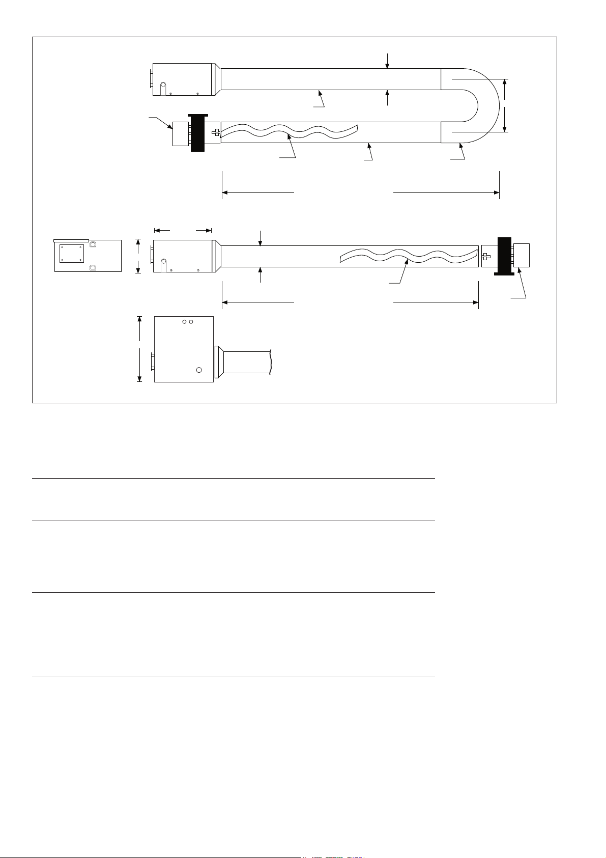
Swirler
Fan Tube
PLAN VIEW
100 mm
254 mm
Heat Exchanger Length
Fan
U-Tube
Flanged Burner Tube
171 mm
273 mm
SIDE VIEW
PLAN VIEW
317 mm
100 mm
Heat Exchanger Length
Fan
Swirler
END VIEW
Figure 1. Blackheat U-Tube and Linear Tube Configurations
22..66 BBUURRNNEERR SSPPEECCIIFFIICCAATTIIOONN
BBuurrnneerr AAiirr PPllaattee
BH15 BH20 BH25 BH30 BH35 BH40 BH45 BH50
Identification Number: 14 15 12 6 7 9 10 11
GGaass CCoonnssuummppttiioonn **
BH15 BH20 BH25 BH30 BH35 BH40 BH45 BH50
Natural G20 (m
3
/h) 1.43 1.91 2.38 2.86 3.34 3.81 4.29 4.77
Natural G25 (m
3
/h) 1.66 2.22 2.77 3.32 3.88 4.43 4.99 5.54
Propane (m
3
/h) 0.56 0.75 0.94 1.13 1.32 1.51 1.69 1.88
Butane (m
3
/h) 0.43 0.57 0.72 0.86 1.00 1.15 1.29 1.43
GGoovveerrnnoorr PPrreessssuurree
BH15 BH20 BH25 BH30 BH35 BH40 BH45 BH50
Butane (mbar) 21.4 19.7 19.2 17.4 18.2 17.9 16.9 18.4
Butane (in wg) 8.6 7.9 7.7 7.0 7.3 7.2 6.8 7.4
Natural G20: 8.7 mbar 3.5 in wg
Natural G25: 11.1 mbar 4.5 in wg
Natural G20 Hi/Lo : 8.7/5.0 mbar 3.5/2.0 in wg
Natural G25 Hi/Lo : 11.1/6.5 mbar 4.5/2.6 in wg
Propane: 27 mbar 10.5 in wg
JJeett NNuummbbeerr
BH15 BH20 BH25 BH30 BH35 BH40 BH45 BH50
Natural G20 & G25
3.4 mm 3.8 mm 4.3 mm 4.7 mm 4.9 mm 5.4 mm 5.8 mm 6.0 mm
Propane/Butane
2.1 mm 2.35 mm 2.7 mm 3.0 mm 3.2 mm 3.4 mm 3.6 mm 3.75 mm
Pressure Couple
1.95 mm 2.25 mm 2.5 mm 2.7 mm 2.9 mm 3.2 mm 3.25 mm 3.4 mm
(*) Based on Gross Caloric Value
Page 7
5
SSeeccttiioonn 33.. UU-TTuubbee HHeeaatteerr IInnssttaallllaattiioonn
3.1 HEALTH AND SAFETY
Blackheat cannot be responsible for ensuring that all
appropriate safety measures are undertaken prior to
installation; this is entirely the responsibility of the
installer. If Blackheat installs the appliance, it is
essential that the contractor, the sub-contractor, or
the owner indicate the presence of combustible materials or halogenated hydrocarbons anywhere in the
premises.
3.2 RELATED DOCUMENTS
Notwithstanding their limited scope, the appliance
should be installed in accordance with relevant
National Codes.
33..33 CCLLEEAARRAANNCCEESS TTOO CCOOMMBBUUSSTTIIBBLLEESS
Before proceeding with installation, ensure that
proper clearances to combustible materials will be
observed in the final installed position of the heater.
Clearance distances may be found in Section 2 of
these instructions.
33..44 IINNIITTIIAALL AASSSSEEMMBBLLYY
3.4.1 Prepare a work area corresponding to the size of
heater selected. The area should be clear and free of
debris. The manufacturers approved layout drawing
should be referred to so that the work area is convenient for the final system position.
3.4.2 Layout the appropriate Figure (3, 4, or 5 depending on
heater model) and keep it at a convenient place for
frequent reference. Pull out every part from the package and lay them out roughly at the position shown in
the assembly drawings. For BH35UT and BH40UT
make sure that the end of the fan tube with the swirler
points away from the U-bend. Keep the bolts and
screws at a convenient place for later usage.
3.4.3 With the suspension holes uppermost, slide the first
and intermediate brackets onto the fan and burner
tubes. For Model BH15, there is no intermediate
bracket. In the following assembly procedures, please
pay attention to this point.
3.4.4 Use two bolts to connect the U-bend and end bracket
together with the suspension holes uppermost. Insert
the plain ends of the burner tube and fan tube into the
two legs of the U-bend, and secure them with four
bolts.
3.4.5 Place intermediate bracket over the ends of the
tubes. Slide bracket onto tubes approximately 500
mm.
3.4.6 Join the burner tube and the remaining plain end tube
using the couplings and bolts provided. See section
4.4.5 for details.
3.4.7 Place the reflectors over the brackets as shown in the
assembly diagrams, and secure them using six screws
at each end. Seal the seam on top of the reflectors
using U-clips at least every 300 mm.
NOTE: Remove PVC coat from stainless steel reflec-
tors.
3.4.8 Insert the quick-links into the holes at the top edges of
the end, intermediate and first brackets.
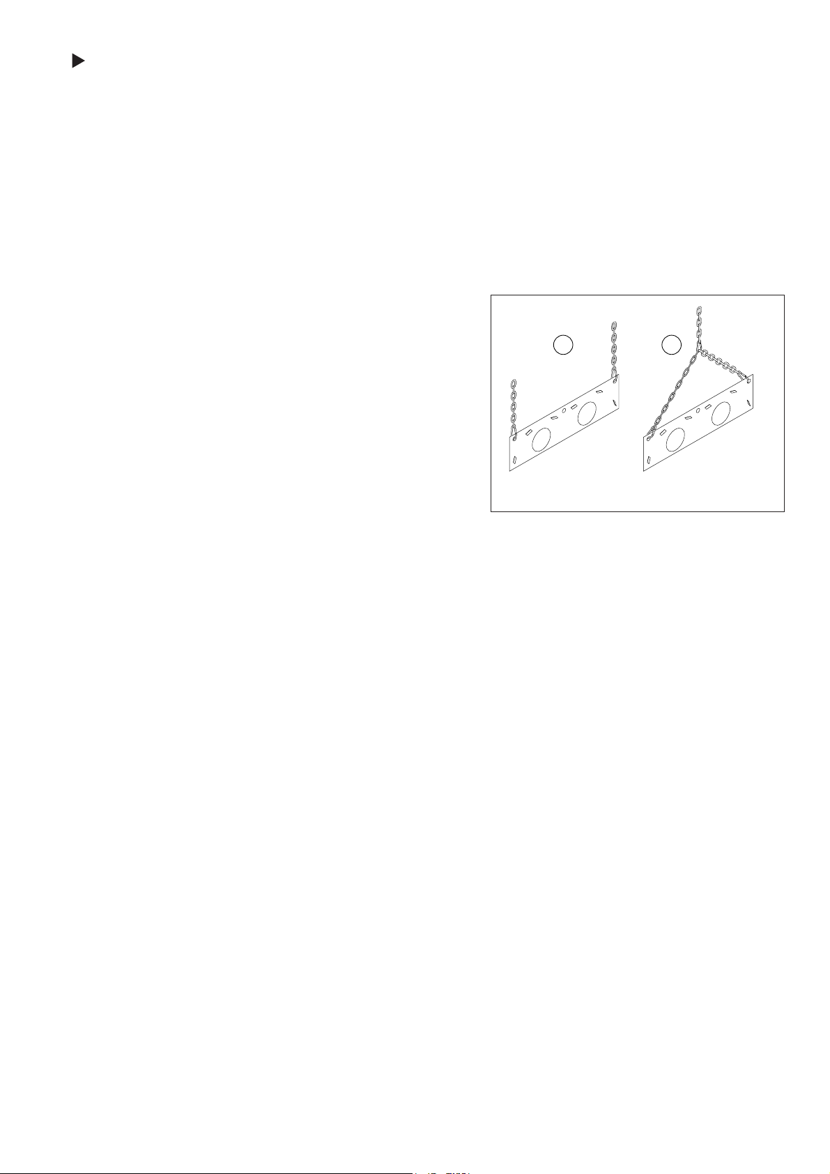
3.4.9 Prepare the hanging chains at the position where the
heater will be located. Suspend the heating system as
recommended below. Use the center holes of the end
and first bracket to lift the heating system into position. Chains used should have 100 kg minimum
breaking load and preferably should be galvanised
finish. Figure 2 shows two suspension methods.
Method A is recommended because it provides a
semi-rigid suspension. Method B is acceptable.
Figure 2. Bracket Suspension
3.4.10 Never lift the assembled heater by passing ropes
around the reflector which would cause severe damage to the reflectors.
3.4.11 When angle mounting the heater, the burner tube
must be the tube nearest the floor and the fan tube is
always furthest from the wall (when suspended adjacent to a wall). It is recommended wherever possible
that the heater is suspended from above from
unequal length chains to effect the necessary angle
(maximum 20° from horizontal). Always allow extra
lengths of chain so that adjustment of angle can be
made to provide the best heat distribution for your
customer.
33..55 FFIINNAALL AASSSSEEMMBBLLYY
3.5.1 Place the gasket on the flange of the burner tube.
Carefully insert the flanged end into the burner box.
Secure the burner on the burner tube using the four
mounting bolts and washers. Use a spanner to tighten
the bolts evenly.
3.5.2 Place the fan assembly onto the end of the last fan
tube. Slide the fan assembly up to its stop. Tighten
the pinch screw on the assembly making sure that the
fan outlet is positioned as required.
Recommended
Suspension
Acceptable
Suspension
A
B
Page 8

6
Table 4. Blackheat U-Tube Heater Parts List
Part No. Description BH15UT BH20UT BH25UT BH30UT BH35UT BH40UT BH45UT BH50UT
1 Burner Assembly with Gasket 1 1 1 1 1 1 1 1
2 S7340K Fan Assembly (includes flange) - Airflow 45 BTFR 1 1 1 1 - - - 3 S7104K Fan Assembly (includes flange) - Torin - - - - 1 1 1 4 S7320K Fan Assembly (includes flange)- Magnetek - - - - - - - 1
5 03051100 Burner Tube, 100 mm x 3048 mm 1 1 1 1 1 1 1 1
6 91409408 Heat Treated Aluminised Tube, 100 mm x 3048 mm - - - 2 2 2 2 2
7 S5127W Fan Tube, 100 mm x 3048 mm with 3048 mm Swirler - 1 1 1 1 1 1 1
8 S5140W Heat Treated Aluminised Tube, 1702 mm - 2 2 - - - 2 2
9 S5134W Fan Tube, 100 mm x 3048 mm with 2134 mm Swirler 1 - - - - - - -
10 S7302K Reflector Kit, 2439 mm, 4 pcs, Alum. - 1 1 - - - - 11 S7301K Reflector Kit, 3048 mm, 2 pcs, Alum. 1 - - - - - - 12 S7303K Reflector Kit, 3048 mm, 4 pcs, Alum. - - - 1 1 1 - 13 S7318K Reflector Kit, 2430 mm, 4 pcs, 3048mm Long, 2pcs,Alum - - - - - - 1 1
14 S7338K Reflector Kit, 2439 mm, 4 pcs, Stls Steel (optional) - 1 1 - - - - 15 S7337K Reflector Kit, 3048 mm, 2 pcs, Stls Steel (optional) 1 - - - - - - 16 S7339K Reflector Kit, 3048 mm, 4 pcs, Stls Steel (optional) - - - 1 1 1 - 17 S7440K Reflector Kit, 2430mm, 4 pcs, 3048mm Long 2pcs Stls Steel (optl) - - - - - - 1 1
18 07290000 U-Bend Assembly 1 1 1 1 1 1 1 1
19 C0176B Quick Link 6 9 9 9 9 9 12 12
20 07281000 First Bracket 1 1 1 1 1 1 1 1
21 07282000 End Bracket 1 1 1 1 1 1 1 1
22 07283000 Intermediate Bracket - 1 1 1 1 1 2 2
23 91107720 U-Clip Package (20 per package) 1 1 1 1 1 1 2 2
24 S7311K Screw Kit 1 1 1 1 1 1 - 25 S7317K Screw Kit - - - - - - 1 1
26 S7401K Support Bracket Package - - - 1 1 1 - 27 S7402K Support Bracket Package - - - - - - 1 1
28 01329600 Standard Coupling Assembly - 2 2 2 2 2 4 4
29 01329700 Coupling Lock - 2 2 2 2 2 4 4
30 S7402K Support Bracket Package 1 - - - - - 1 1
Page 9
7
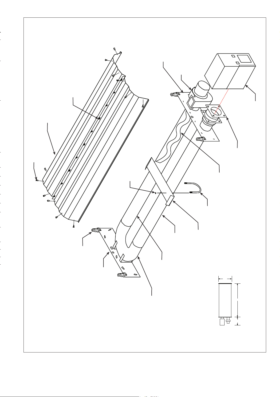
(1) Fan Assembly
(1) Fan Tube 100 mm x 3048 mm
with Swirler
(1) Burner Tube
100 mm x 3048 mm
(1) Burner Assembly
(1) Reflector Kit
(2) 3048 mm long pieces
U-Clips (package of 20)
(4) Quick Links
(1) End Bracket
(1) First Bracket
(1) U-Bend Assembly
(1) Gasket
(1) Swirler
(included in heating tube)
(12) Sheet Metal Screws
Reflector Support Bracket
(1) Nut
(1) U-Bolt
Figure 3. Model BH15UT U-Tube Assembly
c
a
b
a = 534 mm b = 356 mm c = 3050 mm
Page 10
8
(1) Fan Assembly
(1) Burner Tube
100 mm x 3048 mm
(1) Burner Assembly
(1) Reflector Kit
(4) 2439 mm long pieces
(1) Swirler
(included in fan tube)
U-Clips (package of 20)
(6) Quick Links
(1) End Bracket
(1) Intermediate Bracket
(1) First Bracket
(1) U-Bend Assembly
(1) Gasket
(1) Fan Tube
100 mm x 3048 mm
with Swirler
(24) Sheet Metal Screws
(2) Stainless Steel Coupling
(2) Aluminised Tube
100 mm x 1829 mm
Figure 4. Model BH20UT/BH25UT U-Tube Assembly
c
a
b d
a = 534 mm b = 356 mm
c = 2440 mm d = 2440 mm
Page 11
9
(1) Fan Assembly
(1) Fan Tube
100 mm x 3048 mm
with Swirler
(1) Burner Assembly
(1) Reflector Kit
(4) 3048 mm long pieces
U-Clips (package of 20)
(6) Quick Links
(1) End Bracket
(1) Intermediate Bracket
(1) First Bracket
(1) U-Bend Assembly
Gasket
(1) Swirler
(included in fan tube)
(24) Sheet Metal Screws
(1) U-Bolt
Reflector Support Bracket
(Typical 2 Places)
(1) Nut
(2) Stainless Steel Coupling
(1) Burner Tube
100 mm x 3048 mm
(2) Aluminised Tube
100 mm x 3048 mm
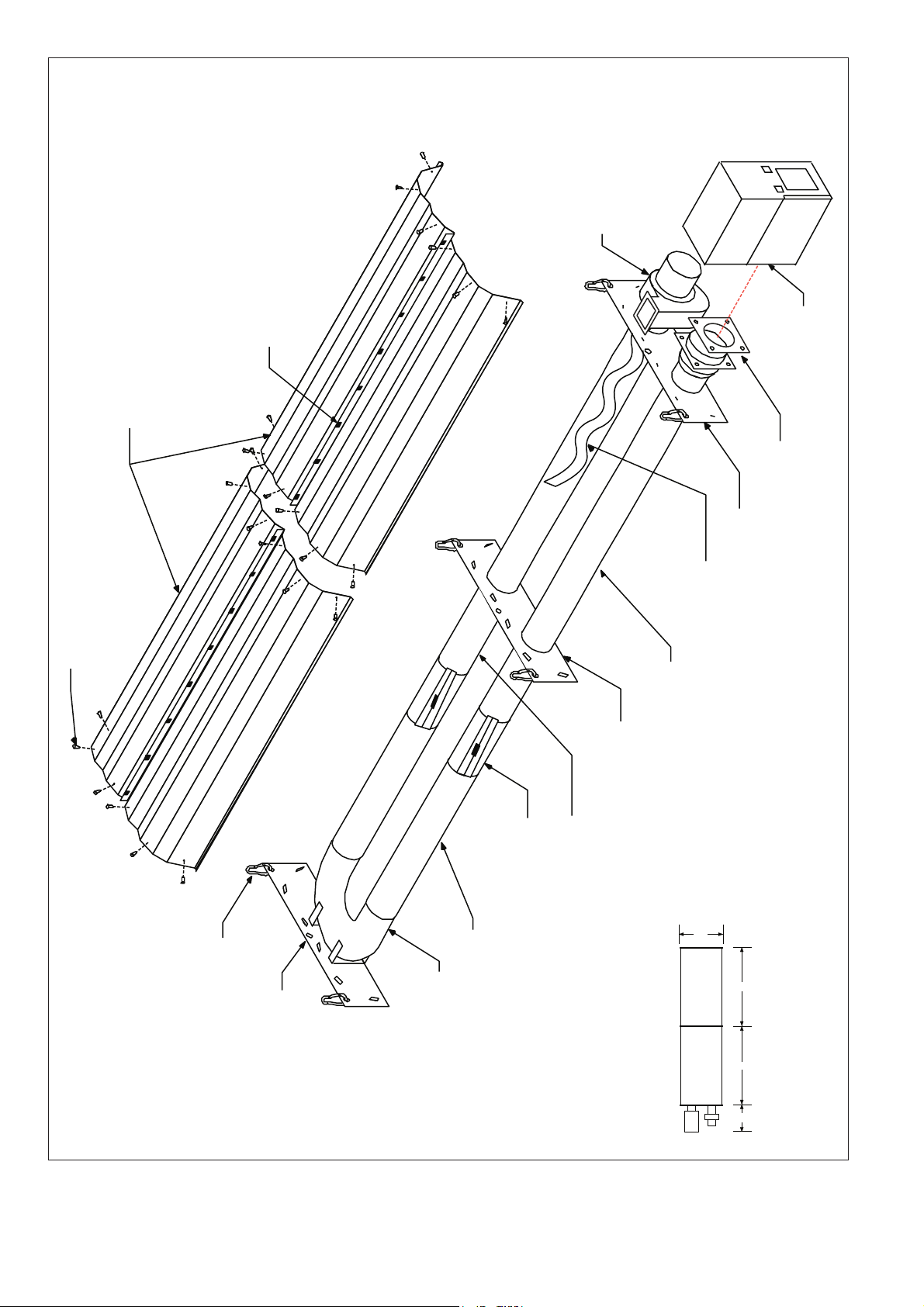
Figure 5. Model BH30UT/BH35UT/BH40UT U-Tube Assembly
c
a
b d
a = 534 mm b = 356 mm
c = 3050 mm d = 3050 mm
Page 12
10
(1) Fan Assembly
(1) Fan Tube
100 mm x 3048 mm
with Swirler
(1) Burner Assembly
(6) Quick Links
(1) First Bracket
(1) U-Bend Assembly
Gasket
(1) Swirler
(included in fan tube)
(1) U-Bolt
Reflector Support Bracket
(Typical 3 Places)
(2) Stainless Steel Coupling
(1) Burner Tube
100 mm x 3048 mm
(2) Aluminised Tube
100 mm x 3048mm
(1) Nut
(1) Intermediate Bracket
(1) Intermediate Bracket
(2) Aluminised Tube
100 mm x 1702 mm
(2) Stainless Steel Coupling
(1) Reflector Kit
(2) 3048 mm long pieces
U-Clips (package of 20)
(24) Sheet Metal Screws
(1) Reflector Kit
(4) 2439 mm long pieces
(1) End Bracket
Figure 6. Model BH45UT/BH50UT U-Tube Assembly
Page 13

11
SSeeccttiioonn 44.. LLiinneeaarr HHeeaatteerr IInnssttaallllaattiioonn
4.1 HEALTH AND SAFETY
Blackheat cannot be responsible for ensuring that all
appropriate safety measures are undertaken prior to
installation; this is entirely the responsibility of the
installer. If manufacturer installs the appliance, it is
essential that the contractor, the sub-contractor, or
the owner indicate the presence of combustible materials or halogenated hydrocarbons anywhere in the
premises.
4.2 RELATED DOCUMENTS
Notwithstanding their limited scope, the appliance
should be installed in accordance with relevant
National Codes.
4.3 CLEARANCES TO COMBUSTIBLES
Before proceeding with installation, ensure that
proper clearances to combustible materials will be
observed in the final installed position of the heater.
Clearance distances may be found in Section 2 of
these instructions.
44..44 IINNIITTIIAALL AASSSSEEMMBBLLYY
4.4.1 Prepare a work area corresponding to the size of
heater selected. The area should be clear and free of
debris. The manufacturers approved layout drawing
should be referred to so that the work area is convenient for the final system position.
4.4.2 Layout the appropriate Figure (9, 10, 11, or 12,
depending on heater model) and keep it at a convenient place for frequent reference. Pull out every part
from the package and lay them out roughly at the
position shown in the assembly drawing. Keep the
bolts and screws at a convenient place for later
usage.
4.4.3 Prepare the hanging chains at the position where the
heater will be located. Chains used should have 100
kg minimum breaking load and preferably should be
galvanised finish. Assemble the two halves of the tube
clamp package using the hex carriage bolt, hex nut
and flat washer. Attach the clamp to the tube and
reflector hanger, and slide the hanger into place on
the burner tube (see Figure 6).
4.4.4 The hanger must be located within 150 mm of the
flange. Slide the next tube and reflector hanger onto
the end of the burner tube. Making sure that the suspension hooks of the hangers are uppermost, lift the
burner tube into the position required. Suspend the
burner tube by connecting the tube and reflector
hangers to chains using the quick links provided.
4.4.5 Slide another tube and reflector hanger onto the next
tube and locate it according to the appropriate Figure.
Lift the tube into its position and connect it with the
burner tube using a stainless steel coupling. Repeat
this procedure to suspend the remaining tube(s) and
connect them to the heater one by one.
4.4.6 For details of the coupling connection, see the following diagram:
Figure 8. Coupling Assembly
To assemble the coupling, hook the free end of the
coupling sleeve into the lanced clip. Place the wide
end of the tapered slide bar on the coupling so that it
moves toward the lanced clip. Insert the two tube ends
into the coupling. Be sure the tube ends are in line
and are flush against the stop pins inside the coupling.
Hammer-drive the slide bar until the coupling is
secured snugly to the tubes. Overdriving the slide bar
will distort the coupling or slide bar lip and will
decrease the holding capability of the coupling.
Impact Block
Tighten
Loosen
When assembling coupling, the wide end of
the slide bar moves toward the lanced clip
Orient coupling so that the impact
block is above tube centerline.
C
L
Stainless Steel
Coupling
Slide Bar
Lanced Clip
Position tube and
reflector hanger no
more than 10 cm (4")
away from the burner
assembly.
Flat washer
and hex nut
Tube clamp
Carriage bolt
Transition tube
Burner assembly
Bow Shackle
Figure 7. General Arrangement Using
Tube Clamp Package
Page 14

12
Coupling should be tight when the slide bar is ±50
mm from the end of the coupling.
4.4.7 Place a reflector over the flanged burner tube and
slide it inside the first tube and reflector hanger. Slide
the next reflector under the first reflector. Overlap the
reflectors using the distance specified in the assembly drawings. Secure the two reflectors in place using
the reflector support straps. Assemble the reflector
support strap according to the following figure:
NOTE: Remove PVC coat from stainless steel reflec-
tors.
Figure 9. Reflector Support Package
4.4.8 Attach the remaining reflectors to the heater using the
same method. Be sure to alternate the overlap of the
reflectors as shown in the assembly drawings.
Reflector
Reflector Support Strap
Wire Form
Reflector Support Package
includes Support Strap, Wire Form, and (2) Screws
For slip joint, loosen screws approx. 2 mm
Heating Tube
Sheet Metal
Screw
Starting at the first reflector support, and alternating
every other support down the length of the heater, the
screws should be loosened 2 mm to allow for expansion of the heating tubes during operation.
4.4.9 After assembling the reflectors, attach the reflector
end caps to the open ends of the reflectors. Punch out
the center section of the end cap, and attach the end
cap to the reflector using at least 6 of the U-clips provided.
44..55 FFIINNAALL AASSSSEEMMBBLLYY
4.5.1 Place the gasket on the flange of the burner tube.
Carefully insert the flanged end into the burner box.
Secure the burner on the burner tube using the four
mounting bolts and washers. Use a spanner to tighten
the bolts evenly.
4.5.2 Place the fan assembly onto the end of the last fan
tube. Slide the fan assembly up to its stop. Tighten the
pinch screw on the assembly making sure that the fan
outlet is positioned as required.
4.5.3 Carefully adjust system pitch at each support to level
the heater. Pitch down (away from burner) 6 mm in
1000 mm.
Table 5. Blackheat Linear Heater Parts List
Part No. Description BH15 BH20 BH25 BH30 BH35 BH40 BH45 BH50
1 Burner Assembly with Gasket 11111111
2 S7353K Fan Assembly (includes flange) - Airflow 45 BTFR 1111 ----
S7103K Fan Assembly (includes flange) - Torin ----111S7105K Fan Assembly (includes flange) - Magnetek -------1
3 03051100 Burner Tube, 100 mm x 3048 mm 11111111
4 S5127W Fan Tube, 100 mm x 3048 mm, with 3048 mm Swirler - 1111111
5 91409408 Heat Treated Aluminised Tube, 100 mm x 3048 mm - 1122233
6 S5134W Fan Tube, 100 mm x 3048 mm, with 2134 mm Swirler 1 -------
7 02750303 Aluminium Reflector, 2439 mm 34466677
8 S5163W Stainless Steel Reflector, 2439 mm 34466677
9 03090100 Tube and Reflector Hanger 34455566
10 01318901 Tube Clamp Package 11111111
11 01329600 Standard Coupling Assembly 12233344
12 01329700 Coupling Lock 12233344
13 03050000 Reflector Support Strap 23355566
14 02750800 Reflector End Cap 22222222
15 E0007576 Bow Shackle 34455566
16 91107720 U-Clip Package 11111111
17 91908004 Wire Form 23355566
Page 15

13
(1) Burner Tube, 100 mm x 3048 mm
(1) Burner Assembly
(3) Reflectors 2439 mm long
(reflectors overlap approx. 700 mm)
Swirler
(included in Fan Tube)
(4) U-Clips
Bow Shackle (Typ.)
Gasket
(1) Tube Clamp Package
(2) Reflector End Caps
(2) Reflector Support Straps
(3) Tube and Reflector Hangers
loose screws
tight screws
(4) U-Clips
(1) Fan Assembly
(1) Stainless Steel Coupling
(1) Fan Tube, 100 mm x 3048 mm,
with Swirler
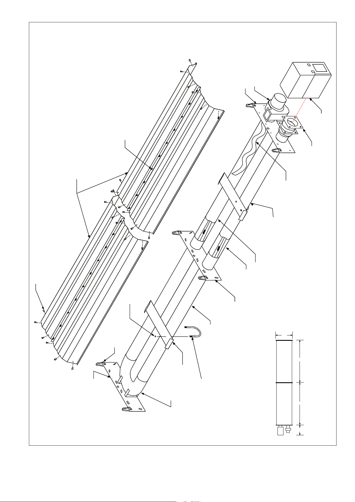
Figure 10. Model BH15ST Assembly
a = reflector width = 365 mm
b = end cap to burner/fan = 150 mm
c = end cap to hanger = 50 mm
d = distance between hangers = 2848 mm
e = burner length = 273 mm
f = burner width = 171 mm
ebc
d
a
d
cb
f
Page 16

14
(1) Fan Assembly
(1) Fan Tube, 100 mm x 3048 mm
with Swirler
(2) Stainless Steel Coupling
(1) Burner Tube, 100 mm x 3048 mm
(1) Burner Assembly
(4) Reflectors 2439 mm long
(reflectors overlap approx. 250 mm)
Swirler
(included in Fan Tube)
U-Clips (package of 20)
(4) Bow Shackles
Gasket
(1) Tube Clamp Package
(2) Reflector End Caps
(3) Reflector Support Straps
(4) Tube and Reflector Hangers
loose screws
tight screws
loose screws
(1) Aluminised Tube, 100 mm x 3048 mm
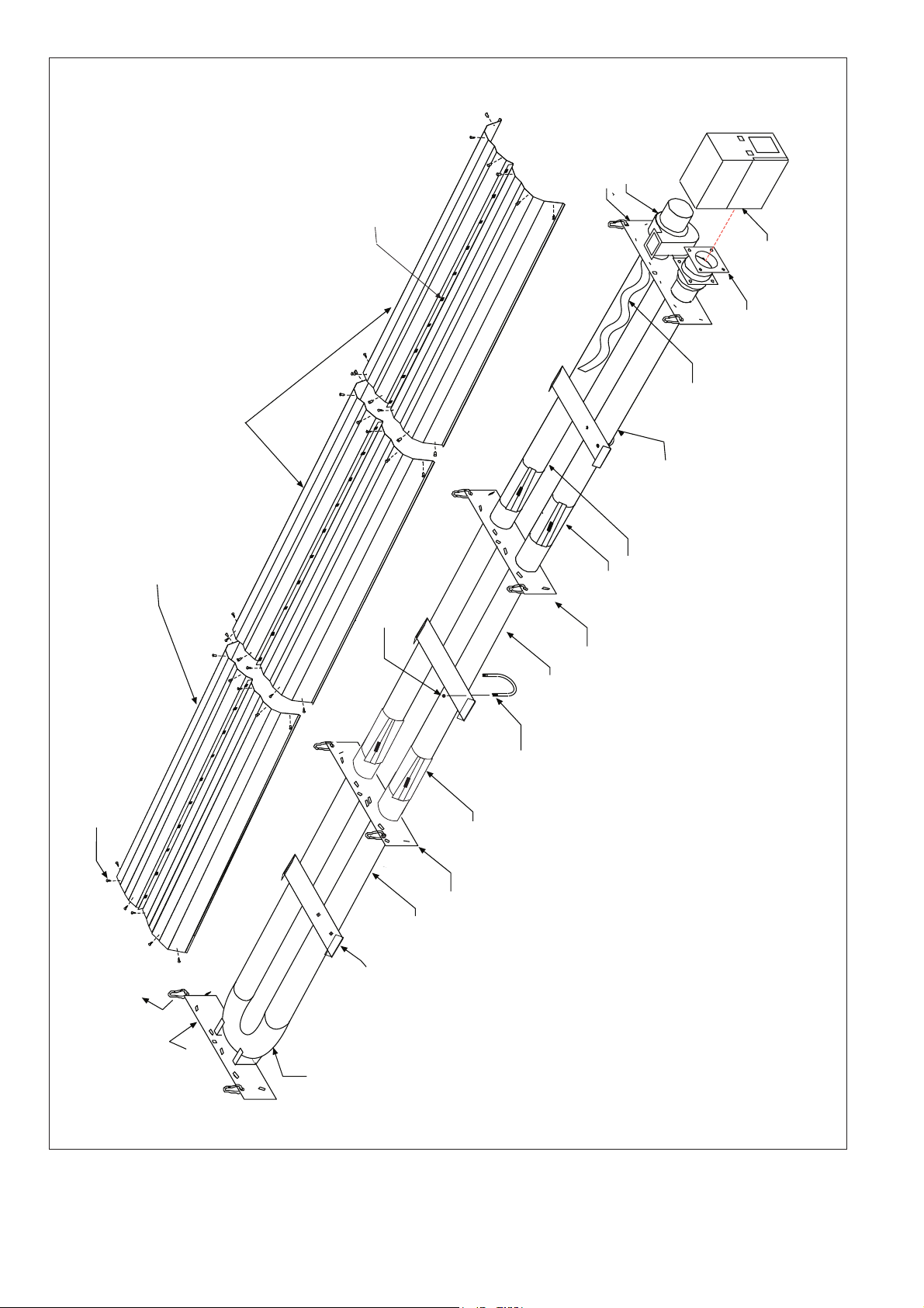
Figure 11. Model BH20ST and BH25ST Assembly
a = reflector width = 365 mm
b = end cap to burner/fan = 150 mm
c = end cap to hanger = 50 mm
d = distance between hangers = 2915 mm
e = burner length = 273 mm
f = burner width = 171 mm
ebc
d
a
d
cb
d
f
Page 17

15
(1) Fan Tube, 100 mm x 3048 mm
with Swirler
(3) Stainless Steel Coupling
(1) Burner Tube, 100 mm x 3048 mm
(1) Burner Assembly
(6) Reflectors 2439 mm long
(reflectors overlap approx. 530 mm)
Swirler
(included in Fan Tube)
Bow Shackle (Typ.)
Gasket
(1) Tube Clamp Package
(2) Reflector End Caps
(5) Reflector Support Straps
(4) Tube and Reflector Hangers
loose screws
tight screws
loose screws
loose screws
tight screws
(4) U-Clips
(4) U-Clips
Damper
(2) Aluminised Tube, 100 mm x 3048 mm
Figure 12. Model BH30ST, BH35ST and BH40ST Assembly
a = reflector width = 365 mm
b = end cap to burner/fan = 150 mm
c = end cap to hanger = 50 mm
d = distance between hangers = 2948 mm
e = burner length = 273 mm
f = burner width = 171 mm
ebc
d
a
d
cb
dd
f
Page 18

16
(1) Fan Assembly
(1) Fan Tube, 100 mm x 3048 mm
with Swirler
(4) Stainless Steel Couplings
(3) Aluminised Tube, 100 mm x 3048 mm
(1) Burner Assembly
(7) Reflectors 2439 mm long
(reflectors overlap approximately 330 mm)
Swirler
(included in Fan Tube)
U-Clips (package of 20)
(6) Bow Shackle
Gasket
(1) Tube Clamp Package
(2) Reflector End Caps
(6) Reflector Support Straps
(6) Tube and Reflector Hangers
loose screws
tight screws
loose screws
loose screws
tight screws
tight screws
(1) Burner Tube, 100 mm x 3048 mm
Figure 13 Model BH45ST and BH50ST Assembly
a = reflector width = 365 mm
b = end cap to burner/fan = 150 mm
c = end cap to hanger = 50 mm
d = distance between hangers = 2968 mm
e = burner length = 273 mm
f = burner width = 171 mm
d d
f
ebc
d
a
d
cb
d
Page 19

17
5.1 HEALTH AND SAFETY
Blackheat cannot be responsible for ensuring that all
appropriate safety measures are undertaken prior to
installation; this is entirely the responsibility of the
installer. If the manufacturer installs the appliance, it
is essential that the contractor, the sub-contractor, or
the owner indicate the presence of combustible materials or halogenated hydrocarbons anywhere in the
premises.
5.2 RELATED DOCUMENTS
Notwithstanding their limited scope, the appliance
should be installed in accordance with relevant
National Codes.
5.3 CLEARANCES TO COMBUSTIBLES
Before proceeding with installation, ensure that
proper clearances to combustible materials will be
observed in the final installed position of the heater.
Clearance distances may be found in Section 2 of
these instructions.
55..44 IINNIITTIIAALL AASSSSEEMMBBLLYY
5.4.1 Prepare a work area corresponding to the size of
heater selected. The area should be clear and free of
debris. The manufacturers approved layout drawing
should be referred to so that the work area is convenient for the final system position.
5.4.2 Establish both the centre point for the unit, and the
centre line of the heater run within the area to be
heated. Along the established centre line of the heating run, layout two of the appropriate heater configurations (Figure 9, 10 or 11). The burner assemblies
should be at opposite ends of the heater run and
should be configured as shown in Figure 13.
5.4.3 At a point directly above the established centre of the
heater system, install a suspension chain for the fan
assembly. Moving outward from this point, and along
the established centre line, establish the remainder of
the chain suspension locations.
5.4.4 Suspend the tube and reflector hangers for the fan
tube, and raise the fan tubes into position.
5.4.5 Assemble the two halves of the tube clamp package
using the hex carriage bolt, hex nut and flat washer.
Attach the clamp to the tube and reflector hanger, and
slide the hanger into place on the burner tube (see
Figure 6).
5.4.6 The hanger must be located within 150 mm of the
flange. Slide the next tube and reflector hanger onto
the end of the burner tube. Making sure that the suspension hooks of the hangers are uppermost, lift the
burner tube into the position required. Suspend the
burner tube by connecting the tube and reflector
hangers to chains using the bow shackles provided.
Repeat procedure for the burner tube at the other end.
5.4.7 Connect the burner and fan tubes using the stainless
steel couplings. Raise the centre tee into position
SSeeccttiioonn 55.. DDoouubbllee LLiinneeaarr HHeeaatteerr IInnssttaallllaattiioonn
between the end of the fan tubes and secure using
the damper couplings provided.
5.4.8 Slide another tube and reflector hanger onto the next
tube and locate it according to the appropriate Figure.
Lift the tube into its position and connect it with the
burner tube using a stainless steel coupling. Repeat
this procedure to suspend the remaining tube(s) and
connect them to the heater one by one. For details of
the coupling connection, see Figure 7.
5.4.9 To assemble the coupling, hook the free end of the
coupling sleeve into the lanced clip. Place the wide
end of the tapered slide bar on the coupling so that it
moves toward the lanced clip. Insert the two tube
ends into the coupling. Be sure the tube ends are in
line and are flush against the stop pins inside the coupling.
Hammer-drive the slide bar until the coupling is
secured snugly to the tubes. Overdriving the slide bar
will distort the coupling or slide bar lip and will
decrease the holding capability of the coupling.
Coupling should be tight when the slide bar is ±50
mm from the end of the coupling.
5.4.10 Place a reflector over the flanged burner tube and
slide it inside the first tube and reflector hanger. Slide
the next reflector under the first reflector. Overlap the
reflectors using the distance specified in the assembly drawings. Secure the two reflectors in place using
the reflector support straps. Assemble the reflector
support strap (see Figure 8).
NOTE: Remove PVC coat from stainless steel reflec-
tors.
5.4.11 Attach the remaining reflectors to the heater using the
same method. Be sure to alternate the overlap of the
reflectors as shown in the assembly drawings.
Starting at the first reflector support, and alternating
every other support down the length of the heater, the
screws should be loosened 2 mm to allow for expansion of the heating tubes during operation.
5.4.12 After assembling the reflectors, attach the reflector
end caps to the open ends of the reflectors. Punch out
the center section of the end cap, and attach the end
cap to the reflector using at least 6 of the U-clips provided.
55..55 FFIINNAALL AASSSSEEMMBBLLYY
5.5.1 Place the gasket on the flange of the burner tube.
Carefully insert the flanged end into the burner box.
Secure the burner on the burner tube using the four
mounting bolts and washers. Use a spanner to tighten
the bolts evenly.
5.5.2 Place the fan assembly onto the branch of the tee;
slide the fan assembly up to its stop. Tighten the pinch
screw on the assembly making sure that the fan outlet is positioned as required. Attach hanging chain to
the flange.
Page 20

18
Table 6. Blackheat Double Linear Heater Parts List
Part No. Description BH2-15ST BH2-20ST BH2-25ST BH2-30ST BH2-35ST
1 Burner Assembly with Gasket 2 2 2 2 2
2 S7353K Fan Assembly (including flange) - Airflow 1 1 - - -
S7105K Fan Assembly (including flange) - Magnatek - - 1 1 1
3 03051100 Burner Tube, 100 mm x 3048 mm 2 2 2 2 2
4 91409408 Heat Treated Aluminised Tube, 100 mm x 3048 mm - 2 2 4 4
5 S5127W Fan Tube, 100 mm x 3048 mm, with 3048 mm Swirler - 2 2 2 2
6 S5134W Fan Tube, 100 mm x 3048 mm, with 2134 mm Swirler 2 - - - -
7 E0009170 Tee, 100 mm x 100 mm x 100 mm 1 1 1 1 1
8 02750303 Aluminium Reflector, 2439 mm 6 8 8 12 12
9 S5163W Stainless Steel Reflector, 2439 mm (optional) 6 8 8 12 12
10 03090100 Tube and Reflector Hanger 6 8 8 10 10
11 01318901 Tube Clamp Package 2 2 2 2 2
12 01329600 Standard Coupling Assembly 4 6 6 8 8
13 01329700 Coupling Lock 4 6 6 8 8
14 03050000 Reflector Support Strap 4 6 6 10 10
15 02750800 Reflector End Cap 4 4 4 4 4
16 E0007576 Bow Shackle 6 8 8 10 10
17 91107720 U-Clip Package 2 2 2 2 2
18 91908004 Wire Form 4 6 6 10 10
Page 21

19
Figure 14. Typical Installation Layouts (Double Linear Heaters)
BH2-15ST
BH2-20ST / BH2-25ST
BH2-30ST / BH2-35ST
BH15
BH20ORBH25
BH30ORBH35
BH15
BH20ORBH25
BH30ORBH35
FAN ASSEMBLY
(Typical)
TEE
(Typical)
STAINLESS STEEL
COUPLING (Typical)
STAINLESS STEEL
COUPLING (Typical)
NOTE: For general arrangement of components (tube
and reflector hangers, reflectors, etc.) refer to
Figures 9, 10 or 11, as required.
Page 22

20
66..11 GGAASS SSUUPPPPLLYY
6.1.1 A gas meter is connected to the service pipe by the
Gas Supply Company. An existing meter should be
checked, preferably by the Company to ensure that
the meter is adequate to deal with the rate of gas supply required.
6.1.2 Installation pipes should be fitted in accordance with
National Standards. Pipework from the meter to the
heater(s) must be of adequate size. Pipes of smaller
size than the heater inlet gas connection should not
be used.
6.1.3 Connect the heater to the gas supply ensuring that the
final connections are as follows:
a) Gas supply pipework is run in medium or heavy
gauge tubing to National Standards terminating in
a Rc1/2 (1/2") BSP thread within 300 mm of the
heater gas inlet.
b) An Rc1/2 (1/2" BSP) mm union cock should be
used and fitted into the supply adjacent to the
heater.
c) A flexible metal hose is connected directly to the
Rc1/2 (1/2" BSP int) connection on the burner.
This metallic hose must conform to National
Standards.
6.1.4 IMPORTANT - The complete installation must be
tested for gas soundness in accordance with National
Standards.
Figure 14. Typical Gas Line Installation (Install According to National Standards)
300 mm
Burner Box
Flex Line Connector
Stainless Steel Flexible Hose
500 mm long
Minimum bend radius 140 mm
Shutoff Cock
REAR VIEW
DOOR-SIDE VIEW
45° 45°
66..22 EELLEECCTTRRIICC SSUUPPPPLLYY
6.2.1 Connect to the electrical supply using a 3 pin plug via
a locally mounted double pole fused switch having a
minimum disconnection of 3 mm on each pole. This
switch should be fused to 3 amps. The burner is fused
at 2 amps. There are no control connections in the
standard burner. Control is affected by interruption of
the main power inlet. See Figures 15 and 16 for the
external wiring details for the single-burner and double
linear heater systems.
6.2.2 All wiring must comply with current I.E.E. Wiring
Regulations and any local regulations which may
apply. Always switch off the supply to the burner and
disconnect by removing the plug before removing the
burner side panel.
6.2.3 In compliance with EN416 clause 4.1.9 Electrical
Operational Safety, any temperature and time control
must be located in the heated area.
SSeeccttiioonn 66.. GGaass aanndd EElleeccttrriicc SSuuppppllyy
Page 23

21
230V
1ph
50Hz
Burner 1
Burner 2
Burner 3
L
N
Earth
Fan 1 Fan 2 Fan 3
Earth
N
L
Blackheat
Thermostat or
Time Clock
Figure 15. Typical External Wiring Diagram (Single-burner Systems)
Figure 16. Typical External Wiring Diagram (Double Linear Systems)
230V
1ph
50Hz
Burner 1 Burner 2
L
N
Earth
Blackheat
Thermostat or
Time Clock
Fan
Earth
N
L
230V
1ph
50Hz
Burner 1 Burner 2
L
N
Earth
Blackheat
Thermostat or
Time Clock
Fan
Earth
N
L
ALTERNA
TE #1
ALTERNATE #2
Page 24

22
L
N
E
BURNER
NEON
FAN
NEON
12345678910
AUTOMATIC CONTROL UNIT
ELECTRODE
purple
grey
230V, 50 Hz
MAINS IN
SOCKET
FAN
SOCKET
green/
yellow
L
E
N
green/
yellow
brown
blue
PRESSURE
SWITCH
NC NO
C
EARTH STUD
green/
yellow
yellow
white
black
black
2A, 230V FUSE
yellow
sense
black
black
blue
blue
brown
green/
yellow
GAS VALVE
EV1
EV2COM
NOISE
FILTER
blue
blue
EARTH
brown
brown
green
blue
Figure 17. Burner Internal Wiring Diagram
Page 25

23
77..11 GGEENNEERRAALL RREEQQUUIIRREEMMEENNTTSS
Heater must be vented in accordance with the proper
national and local codes. The fan may vent to the out-
doors either vertically or horizontally (see Figure 20).
For horizontal venting:
1. Vent must exit building not less than 2.1 m above
grade when located adjacent to public walkways.
2. Vent must terminate at least 1 m above any forced
air inlet located within 3 m.
3. Vent shall terminate at least 1.2 m below, 1.2 m
horizontally from, or 0.3 m above any door, window
or gravity air inlet into building.
4. Locate vent terminal at least 3 m from any open-
ing through which vent gases could enter a building.
5. Use only corrosion resistant materials for the dis-
charge line from the fan to the point of discharge.
6. Vent terminal opening must extend beyond any
combustible overhang.
7. Install vent terminal at a height sufficient to pre-
vent blockage by snow.
8. Protect building materials from degradation by flue
gases.
9. Any portion of flue pipe passing through a com-
bustible wall must be dual insulated or an
approved thimble must be used.
77..22 FFLLUUEE IINNSSTTAALLLLAATTIIOONN
The fan outlet may discharge vertically or horizontally.
Connection should be made using 100 mm minimum
diameter Aluminium or Stainless Steel flue material to
National Standard and must be adapted to insert into
the 100 mm flue adapter. The combined length of flue
run plus fresh air inlet duct should not exceed 16000
mm. Do not use bends in excess of 45°. Consult the
manufacturer if more than 2 x 45° offset bends are
necessary. The flue must be self supporting.
77..33 FFLLUUEELLEESSSS IINNSSTTAALLLLAATTIIOONN ((UU..KK.. OONNLLYY))
If the heater is being installed in an area where combustion products can be dissipated within the building, ensure that the fan outlet is horizontal and away
from the burner. Where installation is close to a wall
(Perimeter system) or other obstruction close to the
fan outlet or wall angle mounted, install the heater so
that the fan tube is the tube furthest from the wall or
obstruction, i.e. the fan will always blow into the building or away from the obstruction.
Figure 18. Flue Connection Detail
77..44 VVEENNTTIILLAATTIIOONN RREEQQUUIIRREEMMEENNTTSS
Detailed recommendations for air supply are given in
the relevant National Standards. There must be an
adequate supply of air for both combustion and general ventilation. Air vents should have negligible resistance. Do not locate air vents where they can be easily
blocked or flooded, or adjacent to any flues or extraction systems carrying flammable vapour.
7.4.1 Flued Installation
Where the heater(s) is flued the space containing it
must have a permanent outside air vent with a minimum effective area of 4.5 cm
2
per kW of heat input. If
mechanical ventilation is employed, the minimum
proven airflow rate shall be 2.35m
3
/h per kW of heat
input.
If the flue is to be horizontally vented through a wall, a
wind-proof terminal must be fitted to outdoor vent pipe
to prevent a back draught.
7.4.2 Flueless Installation
Minimum airflow rate shall be 37.5m
3
/h per kW of
total rated heat input where mechanical ventilation is
used. Where the air change rate is below this minimum, provide additional openings equal to 52 cm
2
per kW total rated heat input; or 1.45 cm2 for each
1m
3
/h per kW below 37.5m3/h per kW of total rated
heat input.
77..55 AAIIRR SSUUPPPPLLYY TTOO BBUURRNNEERR
Where necessary, clean air may be ducted into the
burner box through an added spigot on top of the
burner replacing the existing dust arrest baffle plate.
SSeeccttiioonn 77.. DDiisscchhaarrggee ooff CCoommbbuussttiioonn PPrroodduuccttss
Fan Assembly
Fan Tube
Flue Adapter
Flue Pipe
Attach Flue Adapter with (4) screws,
nuts, and lockwashers.
L
N
E
BURNER
NEON
FAN
NEON
12345678910
AUTOMATIC CONTROL UNIT
ELECTRODE
purple
grey
230V, 50 Hz
MAINS IN
SOCKET
green/
yellow
L
E
N
green/
yellow
brownblue
blue
PRESSURE
SWITCH
NC NO
C
EARTH STUD
blue
green/
yellow
red
yellow
white
black
black
2A, 230V FUSE
yellow
sense
black
black
blue
blue
brown
green/
yellow
GAS VALVE
EV1
EV2
COM
MAINS
FILTER
Page 26

24
Figure 19. Fresh Air Intake Spigot
See section 7.2 for recommendations on duct length.
Air duct should be as straight as possible. Do not use
bends in excess of 45°. Consult the manufacturer if
more than 2 x 45° offset bends are necessary. The
fresh air duct must be self supporting.
77..66 AAIIRR SSUUPPPPLLYY RREEQQUUIIRREEMMEENNTTSS
When fresh air duct is used, follow one of these rules:
A. The flue must penetrate the roof while the fresh
air can penetrate any wall.
B. The flue and fresh air supply must penetrate the
same roof, at a minimum of one meter apart.
C. The flue must penetrate one meter higher than
the fresh air inlet on the same wall.
Figure 20. Air Supply with Flue Configurations
77..77 CCOOMMMMOONN DDUUCCTT
When using a common air inlet duct, always ensure
that the area of the common air inlet duct exceeds
the total area of all air ducts by 20%.
100 mm diameter
Fresh Air Intake Spigot
Dust Arrest
Baffle Plate
Burner
Inlet
Flue
Inlet
Flue
Min. 1 m
Inlet
Flue
Min. 1 m
Roof
Wall
A
C
B
Page 27

25
SSeeccttiioonn 88.. OOppeerraattiinngg tthhee SSyysstteemm
88..11 DDEETTAAIILLEEDD SSEEQQUUEENNCCEE
On connection of power supply the fan motor will start
creating a suction in the tube. Power is also supplied,
via a relay safety circuit, to the fan proving switch and
when suction is created, changes contacts to feed
power to the Automatic Control Unit. At this stage one
neon will light up.
8.1.1 Power to the control causes initiation of an approximate ten (10) seconds purge period following which
the solenoid valves open passing gas at a full rate to
the burner. At the same time a spark is created and
ignition should take place. If ignition of the gas is not
successful the spark will cease and the solenoid will
close after approximately ten (10) seconds. Lockout
will occur. If the gas is ignited, the detection circuit is
energised and switches off the ignition circuit. Both
neons will now light up indicating full running condition.
8.1.2 The heater will continue to run until the power supply
or gas supply is interrupted. Interruption of the electrical supply results in the shutdown of the heater.
Restoration will restart the whole sequence.
Interruption of the gas supply results in loss of flame
followed by one attempt at reignition followed by lockout if unsuccessful.
88..22 TTEESSTTIINNGG
Establish that a satisfactory purged gas supply and an
electrical supply is available to the heater. Ensure that
all time clocks and thermostats are set to call for heat.
8.2.1 With the gas supply cut off at the appliance isolating
cock and the electrical supply isolated by switching off
at the local switch and removing the appliance inlet
plug, open the control chamber secured by the centre
screw. Remove the sealing screw from the pressure
test point and remove the cover cap from the governor.
8.2.2 Turn on appliance isolating cock and connect appliance electrical plug. Ensure that the timer or thermostat, if fitted, are set to call for full gas rate. Switch on
at the local switch. The sequence as described should
take place. If not, refer to detailed fault finding
sequence. When flame is established, check the gas
pressure reading and adjust if necessary. See data
label.
8.2.3 Check the gas pressure at the outlet of the gas valve
to ensure minimum 8.7 mbar (3.5 in. w.g.) pressure
for G20 natural gas or 27 mbar (10.5 in. w.g.) pressure
for propane. See Section 2 for G25 and Butane settings.
8.2.4 Switch off the electrical supply (shutting down the
heater), remove pressure gauge - refit pressure testpoint screw, ensuring a tight gas seal. Replace governor cover cap. Close burner side cover.
88..33 SSYYSSTTEEMM CCHHEECCKKSS
Switch on again at the local switch to ensure smooth
ignition. Carry out the following system checks.
8.3.1 When running turn off the gas supply at the appliance
isolating cock. The heater will immediately shut down
followed by one attempt at restoration followed by
lockout.
8.3.2 When running disconnect the fan plug from the
burner. The unit should shut down within three seconds proving operation of the pressure switch.
88..44 UUSSEERR IINNSSTTRRUUCCTTIIOONNSS
Having satisfactorily tested these Blackheat units
ensure that the client is fully aware of the operation of
the system. Bring this manual to the attention of the
user or purchaser; instruct them in the safe operation
of the heater(s). Advise the user that if the system is
unflued, any reduction in the natural ventilation of the
building may require a flue to be fitted, or additional
ventilation grills will be required.
Page 28

26
SSeeccttiioonn 99 SSeerrvviicciinngg IInnssttrruuccttiioonnss
IMPORTANT: Never use the heater as a support for
ladders or other access equipment. Always test for
gas soundness with a suitable detection fluid after
completing any servicing or exchange of gas carrying
component. On completion of any service/fault finding tasks which require the breaking and remaking of
electrical connections then the checks:- A:Earth
Continuity, B:Polarity and C:Resistance to Earth must
be repeated.
99..11 AANNNNUUAALL PPRROOCCEEDDUURREE
Carry out the following procedure annually. The preferred time would be immediately before the winter
heating period. If very dirty conditions arise it may be
necessary to carry out this procedure more often. If the
unit takes in air through an air duct or filter assembly,
more frequent service may be necessary.
9.1.1 Isolate the heater from the gas and electricity supply
by shutting off the appliance cock and disconnecting
the union connector, switching off the local electrical
supply and removing the appliance plug.
9.1.2 Remove the fan plug from the burner. Unscrew the
securing screws on the burner flange. The burner can
now be removed. Unscrew the securing screw on the
fan flange spigot. The fan can now be removed.
9.1.3 Remove the fan and burner independently to floor
level and clean both items internally using a soft
brush and compressed air if available. Take care not
to damage the internal parts of the burner. Check fan
impeller for cleanliness and that free rotation is available. When removing burner take care not to disturb
the gasket on the flanged burner tube.
9.1.4 The electrodes are an integral part of the Burner
Head. To check spark gap remove the securing screws
on the electrode and withdraw it ensuring the gasket
is not damaged. Spark gap on electrode should be
approximately 3 mm.
9.1.5 With burner and fan removed, clean the outer surfaces of the tubes using a brush and wipe the inner
surface of the reflector with a soft damp cloth - use a
household detergent if necessary. Never use abrasive
cleaners on the the reflectors.
9.1.6 Re-assemble the burner and fan in reverse order.
Carry out the Testing Procedure 8.2.
99..22 CCOOMMPPOONNEENNTT RREEMMOOVVAALL
First isolate the heater from the gas and electricity
supply; shut off the appliance cock, disconnect the
gas union connection; switch off the local electrical
supply and remove the appliance plug.
Entry to the burner assembly is gained by removing
the two (2) door screws and opening the hinged side
cover. Entry to the combustion chamber is gained by
removing the combustion chamber cover (7 screws).
9.2.1 Electrode (see section 9.1.4)
9.2.2 Burner Head/Injector Jet
When the cover is removed completely, the burner
assembly is exposed. Unscrew the burner cup.
Remove brass injector jet (orifice). Replace in reverse
sequence.
9.2.3 Solenoid Valve/Governor
Remove burner head as 9.2.2. Unscrew 4 mm slotted
screws on top of burner securing the solenoid/governor body. Withdraw the four wires tagged to the solenoid (TEKNIGAS), or the four wires between the
solenoids (SIT). The solenoid/governor and fittings can
now be withdrawn from the compartment.
The solenoid(s) can be removed from the body by
extracting the circlip and sliding (TEKNIGAS), unscrewing central screw (SIT). Replace in reverse sequence.
Note: Earth is green/yellow.
9.2.4 Automatic Flame Control Unit
Remove grey ignition lead. Withdraw the 10 point edge
connector. Unscrew four (4) screws from the cover.
Replace if faulty. Refit in reverse sequence.
9.2.5 Pressure Switch
Disconnect the two (2) rubber tubes. Remove wires
from the three blades. Remove two (2) screws which
secure the pressure switch to the burner. Remove
pressure switch.
Replace pressure switch if faulty and refit in reverse
sequence ensuring that the rubber tubes are reconnected to the switch correctly.
Not
e: Wires fitted as follows:
NO - Yellow
NC - White
Common - Black
9.2.6 Neons
Remove the two push on connectors and remove the
neons by pushing downwards. Replace in reverse
sequence.
9.2.7 Fuse
Pull out drawer containing fuse in the panel mounted
mains socket.
Page 29

27
It is the installer’s responsibility to follow these instructions and
to insure that all local and national codes are followed. Insure
that you are capable of performing all steps and read the
entire section before beginning this procedure.
NOTE: For conversion between G20 and G25, or Propane and
Butane, no change in jet size is necessary; remove (2)
screws from control side door, open and proceed to step
10.3.5.
1100..11 GGAASS CCOONNVVEERRSSIIOONN KKIITTSS IINNCCLLUUDDEE::
- Jet as required; see burner specifications (pg. 4)
* - Governor spring. (Propane/Butane: Green)
(Natural: Silver)
- Valve/governor label.
- Burner unit label for gas conversion (to natural G20,
G25, propane or butane).
(*) TEKNIGAS valves only
1100..22 RREEQQUUIIRREEDD TTOOOOLLSS::
- Spanner 13 mm (1/2") - to remove jet.
- Manometer - minimum 0-28 mBar (0-11" W.G.)
- Phillips screwdriver (#2)
-or-
- 1/4” Nut Driver
- Flat blade screwdriver.
- Spanner 8mm - to adjust Governor (SIT valve only)
1100..33 CCOONNVVEERRSSIIOONN PPRROOCCEEDDUURREE::
10.3.1 Isolate gas and electric supply; remove fresh air duct
if necessary.
10.3.2 Remove cover screws; withdraw the edge connector
and the ignition lead from the automatic control unit;
set cover aside.
10.3.3 This step is for the TEKNIGAS model valve only.
Remove governor screw and spring; replace with
spring included in kit and refit governor screw. See
Figure 21 - Governor Spring Replacement.
10.3.4 Remove burner cup and jet; replace with the jet provided in the kit. Reinstall the burner cup. See Figure
24 for proper position of cup relative to the air plate.
10.3.5 Attach valve/governor label to side of valve body.
10.3.6 Attach gas conversion label indicating gas type to
burner housing adjacent to data plate; fill in governor
pressure setting.
10.3.7 Replace door assembly and refit edge connector and
ignition lead to the automatic control unit; do not
attach screws to control side door at this time.
NOTE: For propane/butane pressure couple (TEKNIGAS valve, Italy only): turn governor screw down
(clockwise) until the regulator is at the bottom;
replace the plastic capscrew over the governor spring;
proceed to step 10.3.12.
10.3.8 Attach one end of hose to the governor pressure tap
and the other end to the pressure side of a manometer.
10.3.9 Turn on gas and electrical supply, operate unit.
10.3.10 Set governor pressure according to the burner specifications (pg. 4) by turning the governor screw until the
proper pressure is read on the manometer.
10.3.11 Shut off unit and remove manometer. Return the shut
off screw in the governor pressure tap to the off position and replace the screw cap over the governor
spring (TEKNIGAS valve only).
10.3.12 Reinstall screws to the control side door and refit the
fresh air duct if necessary.
10.3.13 Review section 9.1 servicing instructions: annual pro-
cedure. Return unit to service.
1100..44 AADDJJUUSSTTMMEENNTT OOFF SSTTEEPP-OOPPEENNIINNGG FFLLOOWW RRAATTEE
((SSIITT VVAALLVVEE OONNLLYY))::
10.4.1 To adjust, gradually turn screw marked “I Step” until
ignition is prompt and silent. Clockwise rotation: start
flow decreases. (see Figure 22). The step-open flow
rate should allow 2.5 mbar (1.0 in wg) gas pressure to
the jet. After proper adjustment of the step-open flow
rate, the valve will fully open within a few seconds and
the governor pressure may then be set.
10.4.2 Wait at least 40 seconds after deenergization of solenoids before checking for proper ignition.
SSeeccttiioonn 1100.. GGaass CCoonnvveerrssiioonn IInnssttrruuccttiioonnss
Page 30

28
Governor Screw
(no replacement spring)
I-Step Adjustment
Outlet Pressure Tap Inlet Pressure Tap
Teknigas Gas Valve
Plastic Capscrew
Replacement Spring
Governor Screw
Air Plate
Burner Cup
(center horizontally)
Jet
Electrode
16 mm
Governor Screw
and Spring
Inlet Pressure TapOutlet Pressure Tap
Figure 21 TEKNIGAS Valve Spring Replacement
Figure 22 SIT Valve Detail Figure 24 Burner Cup Position
Figure 23 TEKNIGAS Valve Detail
Page 31

29
Replace automatic
control unit.
(P/N 90438700)
YES
NO
Remove obstruction.
Is the flue pipe or the inlet of
the burner obstructed?
YES
NO
Carefully reset spark gap
to 3 mm.
Is the igniter gap
set at 3 mm?
YES
NO
Replace Electrode and
ignition wire as needed.
(P/N 90427403)
Replace air switch.
Fan bearings may have
failed. Replace fan.
NO
YES
Check relay wiring
(if applicable) and wiring
to the burner.
Unplug burner. Does the
fan turn freely?
NO
YES
Is there power (230V) at
the burner?
Check thermostat wiring
and replace thermostat if
necessary.
NO
YES
Unplug burner and check
Electroder and ignition wire.
Are they damaged?
START
YES
NO
NO
YES
Place a jumper across the
thermostat terminals.
Does the fan turn on?
Is there spark at the igniter?
YES
NO
Turn up thermostat.
Does the fan turn on?
NO
Is the fan obstructed?
Replace fan.
NO
YES
Are the hoses to the air
switch secure and leak free?
Repair, replace, or tighten
hoses as necessary.
Check 2-Amp fuse in Mains
Inlet. Replace as required.
NO
Remove Black & White
leads from the air switch;
place jumper between leads.
Does the fan turn on?
NO
YES
Remove obstruction.
Remove Black & Yellow
leads from the air switch;
place jumper between leads.
Is there a spark?
Replace air switch
(P/N 90436711)
Is there power out from
pin 10 on ignition module?
Replace ignition module.
NO
YES
Figure 25. Troubleshooting Flow Chart
Page 32

30
Page 33

31
SSeeccttiioonn 1111.. RReeppllaacceemmeenntt PPaarrttss
A
B
C
D
E
F
G
H
I
J
K
L
M
N
O
Figure 26. Burner Internal Components
Page 34

32
TTaabbllee 77.. RReeppllaacceemmeenntt PPaarrttss
Item Part Number Description
A 90438700 Automatic Control Unit
B 91319900 Fuse, 2 amp, 5 mm x 20 mm
C 91220700 Flex Line Adapter
D 90436711 Air Switch
E 91320602 Amber Neon Lamp
F 90033100 Gas Valve
G Regulator Spring and Governor Screw
H Governor Pressure Tap
I 03090702T Flex Manifold
J 96212100 Star Washer
K Jet (see section 2 of these instructions) - Orifice
L 03020100 Burner Cup Assembly
M 02553203 Mica Window Assembly
N 90427403 Electrode Assembly
not shown 02558501 Electrode Gasket
O 07230000 Dust Arrest Baffle Plate
not shown 90438900 Filter, Noise - RFI
not shown 91319601 Edge Connector - 10 way
not shown 90427704 Ignition Wire
not shown 07260000 Outside AIr Kit
91911700 100 mm Collar
07261000 Outside Air Mounting Plate
94118106 #8 x 3/8 Washer Head Screws
not shown 02568200 Burner Tube Gasket
Page 35

33
All Blackheat product bear CE marking signifying that
they comply with all relevant CE directives.
The Blackheat Warranty means that only the best
material and workmanship are employed in the manufacture of Blackheat products.
WARRANTY COVERAGE:
Blackheat Ltd. (“Seller”) warrants that entire heating
systems sold by it (individually a “System”) and any replacement parts which it sells relating to any System (“Parts”)
shall be free from defects in workmanship and material for
the time periods described as follows. With respect to a
System this warranty shall apply for a period of one year
from delivery to the original purchaser (“Buyer”). With
respect to Parts, this warranty shall apply for the longer of
the original System warranty period or for a period of one
year. (“Systems” and “Parts” are hereinafter collectively
referred to as “Products”.) This warranty extends only to the
original purchaser of Products.
Seller manufactures products which are designed only
to provide predetermined ranges of heat rises in various
enclosures when properly used in systems designed by purchaser or others and installed by others. Seller makes no
representation or warranty with respect to the effect upon
enclosure, or upon any of the contents of the enclosure,
including, without limitation, all plant or animal life, kept or
processed in the enclosure subject to the limitations outlined below.
WARNING:
This warranty is void if the products have been damaged due to accident, abuse, mishandling or any other
cause whatsoever other than defects in material or workmanship. Specifically, Seller’s warranty shall not apply: (a)
to damage to Products when used in an atmosphere containing halogenated hydrocarbons or other corrosive chemicals. Some compounds in the air can be ingested into the
equipment and can cause an accelerated rate of corrosion
of some of the Products. The use of such chemical compounds in or near the enclosure should be avoided where:
(a) longer life of the burner, tubing and other parts is desirable; (b) to any damage when used in the vicinity of any
combustible or explosive materials; (c) to Products which
have been repaired or replaced with other than factory
parts, modified in any way, misused or damaged, or which
have been installed or used contrary to Seller’s written
instructions or manuals; (d) to any damage resulting from
improper service or a lack of proper maintenance; or (e) to
any damage resulting from failure to comply strictly with
these Installation and Servicing Instructions in all respects.
LIMITATIONS OF WARRANTY:
Other than as stated herein or in any other warranty of
Seller, there are no other warranties of any kind whatsoever, express or implied, and all other express and all
implied warranties of merchantability and/or fitness for any
particular purpose are hereby specifically disclaimed.
EXCLUSIVE REMEDY:
The sole and exclusive remedy for any loss, damage or
liability, or otherwise, is limited to the obligation of Seller to
repair or replace parts, at its factory, of any product owned
by original buyer and returned to the Seller’s factory within
one year after invoice, with transportation charges prepaid,
which examination reveals to have been defective. Under no
circumstances shall Seller be liable for any loss, damage,
cost, expenses, or incidental or consequential damages of
any kind, in connection with the sale, installation, use, maintenance, or repair of any Product.
BUYER RESPONSIBLE FOR DATA:
Seller and its representative may furnish Buyer, upon
Buyer’s request, data relating to the function and use of
Products. Seller shall not be liable for loss, damage, cost,
expenses or incidental or consequential damages of any
kind, sustained directly or indirectly, by any person, or to any
property, if Buyer adopts and uses such data in whole or in
part.
LIMITATIONS ON AUTHORITY OF REPRESENTATIVES:
No representative of Seller, other than an Executive
Officer, has authority to change or extend these provisions.
Changes or extension shall be binding only if confirmed in
writing by Seller’s duly authorized Executive Officer.
Direct any question or warranty claims to the original
installer:
Company:__________________________________________
Address:___________________________________________
__________________________________________________
Phone: ____________________________________________
Or to: Blackheat Ltd.
12 Cobham Road
Ferndown Industrial Estate
Wimborne, Dorset BH21 7PS
SSeeccttiioonn 1122.. TThhee BBllaacckkhheeaatt WWaarrrraannttyy
BLACKHEAT SERVICE AGREEMENT:
The Blackheat Warranty may be further extended by
the customer entering into a Blackheat Service
Agreement whereby Blackheat or an appointed
Blackheat Service Agent carries out routine inspection
and service work in return for an annual premium
payable by the owner. In this way, Blackheat customers
can continue to enjoy the full benefit and value of
Blackheat products for many years to come.
Page 36

34
Page 37

35
Due to a policy of continuous development, we reserve the
right to change specifications without notice.
Printed in UK
All rights reserved. No part of this work covered by the
copyrights herein may be reproduced or copied in any form
or by any means – graphic, electronic, or mechanical,
including photocopying, recording, taping, or information
storage and retrieval systems – without written permission
of Roberts-Gordon Europe Ltd.
 Loading...