

Page 1
DO NOT store or use petrol or other
flammable vapors and liquids in the
vicinity of this or any other appliance.
FOR YOUR SAFETY
If you smell gas:
1. Open windows.
2. DO NOT try to light any
appliance.
3. DO NOT use electrical
switches.
4. DO NOT use any telephone
in your building.
5. Leave the building.
6. Immediately call your local
gas supplier after leaving
the building. Follow the gas
suppliers instructions.
7. If you cannot reach your gas
supplier, call the Fire
Department.
®
Blackheat
Vacuum Assisted
Linear & U-Tube
Gas Fired Radiant
Heating
Systems
Installation, Operation &
Service Manual
Improper installation, adjustment, alteration, service
or maintenance can result in death, injury or property
damage. Read the installation, operation and service
manual thoroughly before installing or servicing
this equipment.
Installation must be done by a contractor qualified
in the installation and service of gas-fired heating
equipment.
WARNING
BH15
BH20
BH25
BH30
BH35
BH40
BH45
BH50
Installer
Please take the time to read and understand
these instructions prior to any installation.
Installer must give a copy of this manual to the owner.
Owner
Keep this manual in a safe place to provide your
serviceman with information should it become
necessary.
Hurll Nu-Way Pty Ltd
14 Aristoc Road
GLEN WAVERLEY VIC 3150
Telephone: +61 3 9561 2100
Fax: +61 3 9560 8992
www.rg-inc.com
170101AUNZ Rev. 2 4/03
Page 2
TABLE OF CONTENTS Note: Pages 2,16,17,18,23,32,35,46,54,55 have been deleted as not relevant.
SECTION 1: Heater Safety......................................................1
SECTION 2: Installer Responsibility .....................................1
2.1 Low Level User Instructions.........................................1
2.2 Halogenated Hydrocarbons.........................................1
2.3 National Standards and Applicable Codes ..................1
SECTIO N 3: Critical Consideratio ns ....... .. .................... .. ... ...3
3.1 Minimum Required Clearances to Combustibles.........3
3.2 Clearance Data - Linear ................4
3.3 Clearance Data -U Tube.................6
SECTIO N 4: Spe c if ic a tions ................................ .. ... ......... ... .. . 8
4.1 Material Specifications................................................. 8
4.2 Heater Specifications...................................................8
4.3 Venting Specifications..................................................8
4.4 Suspension Specifications........................................... 8
4.5 Controls Specifications ................................................ 8
4.6 Linear Heater...............................................................9
4.8 U-Tube Heater .............................................................9
4.9 Burner Specifications................................................. 10
SECTION 5: Major Component Descriptions ..................... 11
SECTIO N 6: Gen er a l Sus p e n s io n Details ........ ..................12
6.1 Suspension Details .................................................... 12
SECTION 7: Linear Heater Installation........................... ...13
7.1 Linear Standard Parts List .........................................13
7.3 Burner Tube Installation ............................................ 19
7.4 Coupling and Tube Assembly....................................19
7.5 Tube Clamp Package Installation..............................21
7.6 Reflector Installation .................................................. 21
SECTIO N 1 2: Ventin g ............... .. .. .................... .. ... .......... .. .. ..42
12.1 Flue Installation ........................................................42
12.2 Flueless Installation (U.K. Only)...............................42
12.3 Ventilation Requirements ......................................... 42
12.4 Outside Combustion Air Supply ...............................43
12.5 Common Duct ..........................................................43
SECTIO N 1 3: Ga s P ip in g . ... ................... ... .. .......... .. ... ......... ..44
SECTIO N 1 4: W ir in g.. ................... ... .. .......... .. ... .......... .. ... ...... 4 5
14.1 BLACKHEAT® Typical External Wiring Diagram
(Linear or U Tube)............................................................45
14.5 BLACKHEAT® Internal Wiring Diagram .................47
SECTIO N 1 5: Ope r a tio n ...... ................... ... .. .......... .. ... ......... ..48
15.1 Heater Lockout Indication (Optional)........................48
15.2 Testing......................................................................48
15.3 Commisioning ..........................................................48
15.4 System Checks ........................................................49
15.5 User Instructions......................................................49
SECTIO N 1 6: Se r v ic ing Instru c tio n s .. .. .......... .. ... ................ 5 0
16.1 Annual Procedure ....................................................50
16.2 Component Removal ...............................................50
SECTION 17: Troubleshooting.............................................52
17.1 Troubleshooting Flow Chart (Linear and
U-Tube) ............................................................................52
SECTION 8: U-Tube Heater Installation ..............................24
8.1 U-Tube Standard Parts List........................................24
8.2 Critical Hanger Placement.........................................27
8.3 Burner Tube and Fan Tube Installation ....................27
8.4 U-Tube Support Bracket Assembly Installation .........28
8.5 Coupling and Tube Assembly....................................29
8.6 Tube Installation ........................................................30
8.7 U-Tube Installation .................................................... 30
8.8 Reflector Installation .................................................. 31
SECTION 10: Burner & Fan Installation ..............................33
10.1 Burner Installation.................................................... 33
10.2 Fan Assembly.......................................................... 33
10.3 Linear & U-Tube Fan Installation..............................34
SECTION 11: Optional Heater Accessories........................36
11.1 Reflector Side Extension Installation ....................... 36
11.2 Decorative Grille Installation....................................37
11.3 Protective Grille Installation ..................................... 38
11.4 Sports Hall Guard Installation ..................................39
11.5 Universal Shield Installation.....................................40
11.6 Undershield Installation ...........................................41
17.3 Manifold Gas Pressure Setting ................................56
SECTIO N 1 8: Re p l ac e me n t Pa r ts..... ... ......... ... .. .......... ... .. ....57
© 2001
All rights reserved. No part of this work covered by the copyrights herein may be reproduced
or copied in any form or by any means - graphic, electronic, or mechanical, including
photocopying, recording, taping or information storage and retrieval systems - without the
written permission of Roberts-Gordon.
Page 3

TABLE OF FIGURES
Figure 1: Deleted
Figure 2: Linear Horizontal Mounts ...............4
Figure 3: Linear, One Side Reflector..............4
Figure 4: Linear, Two Side Reflectors ............4
Figure 5: Linear, 45° Mount............................4
Figure 6: Linear, 1 Foot and 2 Foot Deco
Grille ..........................................................................5
Figure 7: Linear, Protective Grille...................5
Figure 8: Linear, Venting ................................5
Figure 9: U-Tube, Horizontal Mount .......................................... 6
Figure 10: U-Tube, One Side Reflector ..................................... 6
Figure 11: U-Tube, Two Side Reflectors ...................................6
Figure 12: U-Tube, Full 45° Mount............................................6
Figure 13: U-Tube, Opposite 45° Tilt......................................... 7
Figure 14: U-Tube, Protective Grille .......................................... 7
Figure 15: U-Tube, Venting ....................................................... 7
Figure 16: BLACKHEAT® Linear and U-Tube ........................10
Figure 17: BLACKHEAT® Linear General Assembly
Overview................................................................ 14
Figure 18: BLACKHEAT® Linear Layout Overviews .............. 15
Figure 19: Deleted
Figure 20: Deleted
Figure 21: Reflector Overlap Detail......................................... 22
Figure 22: BLACKHEAT® BH15UT Assembly Overview .......25
Figure 23: BLACKHEAT® U-Tube Layout Overviews.............26
Figure 24: Deleted
Figure 25: Typical Manifold Layout (Linear and U-Tube
Configuration) ........................................................ 32
Figure 26: Individual Flue Connection Detail..........................42
Figure 27: Fresh Air Intake Spigot .......................................... 43
Figure 28: Air Supply with Flue Configurations.......................43
Figure 29: Gas Connection with Stainless Steel Flex
Connector .............................................................. 44
Figure 30: Sequence of Operation Chart................................ 48
Figure 31: Burner Cup Position............................................... 50
Page 4
SECTION 1: HEATER SAFETY
Your Safety is Important to Us!
This symbol is used throughout the manual
to notify you of possible fire, electrical or burn
hazards. Please pay special attention when
reading and following the warnings in these
sections.
SECTION 1: HEATER SAFETY
A wall tag is supplied with the BLACKHEAT® heater as a
permanent reminder of the safety instructions and the
importance of the minimum required clearances to
combustibles. A copy of the wall tag is illustrated on Page
2, Figure 1. Peel off the backing of the adhesive strips on
the rear surface of the tag and position the tag on a wall
near the BLACKHEAT® heater (e.g. thermostat or
ROBERTS GORDON
®
BZC Microprocessor Controller).
WARNING
Installation, Service and Annual Inspection of heater
must be done by a contractor qualified in the
installation and service of gas-fired heating equipment.
Read this manual carefully before installation,
operation, or service of this equipment.
Failure to follow these instructions can result in death,
injury or property damage.
This heater is designed for heating non-residential indoor
spaces. Do not install in residential spaces. These
instructions, layouts , AS5601/AG 601,local codes and
ordinances, and applicable standards that apply to gas
piping, electrical wiring, venting, etc., must be thoroughly
understood before proceeding with the installation.
SECTION 2: INSTALLER RESPONSIBILITY
• To install the heater, as well as the gas and electrical
supplies, in accordance with applicable specifications
and codes. Roberts-Gordon recommends the
installer contact a local building inspector or Fire
Marshal for guidance.
• To use the information given in a layout drawing and
in the manual together with the cited codes and
regulations to perform the installation.
• To install the heater in accordance with the Clearances to Combustibles.
• To furnish all needed materials not furnished as
standard equipment.
• To plan location of supports.
• To provide access to burners for servicing on all
sides, for burner removal.
• To provide the owner with a copy of this installation,
operation and service manual.
• To never use heater as support for ladder or other
access equipment and never hang or suspend anything from heater.
2.2 Halogenated Hydrocarbons
CAUTION
Do not use heater in an area containing corrosive
chemicals.
Avoid the use of corrosive chemicals to ensure a
longer life of the burner, tubing and other parts.
Failure to follow these instructions can result in
property damage.
Roberts-Gordon cannot be responsible for ensuring that
all appropriate safety measures are undertaken prior to
installation; this is entirely the responsibility of the
installer. It is essential that the contractor, the subcontractor, or the owner identifies the presence of
combustible materials or halogenated hydrocarbons*
anywhere in the premises.
* Halogenated Hydrocarbons are a family of chemical compounds characterized by the presence of halogen elements
(flourine, chlorine, bromine, etc.). These compounds are
frequently used in refrigerants, cleaning agents, solvents, etc. If
these compounds enter the air supply of the burner, the lifespan
of the heater components will be greatly reduced. An outside air
supply must be provided to the burners whenever the presence
of these compounds is suspected. Warranty will be invalid if the
heater is exposed to halogenated hydrocarbons.
2.3 National Standards and Applicable Codes
All Appliances must be installed in accordance with the
latest revision of AS5601/AG 601 and other relevant
codes. This refers also to the electric, gas and venting
installation. Note: Additional standards for installations in
Public Garages, Aircraft Hangars, etc. may be applicable.
2.1 Low Level User Instructions
In all situations, clearances to combustibles must be
maintained. Failure to observe clearances to
combustibles can result in death, severe injury or
property damage. Signs should be posted in storage
areas to specify the maximum stacking height of items
placed below heater to maintain required clearances to
combustibles. Minimum clearances must be maintained
from vehicles parked below the heater. Caution should be
used when running the system near combustible
materials such as wood, paper, rubber, etc.
Consideration should be given to partitions, storage
racks, hoists, building construction,etc.
1
Page 5
SECTION 3: CRITICAL CONSIDERATIONS
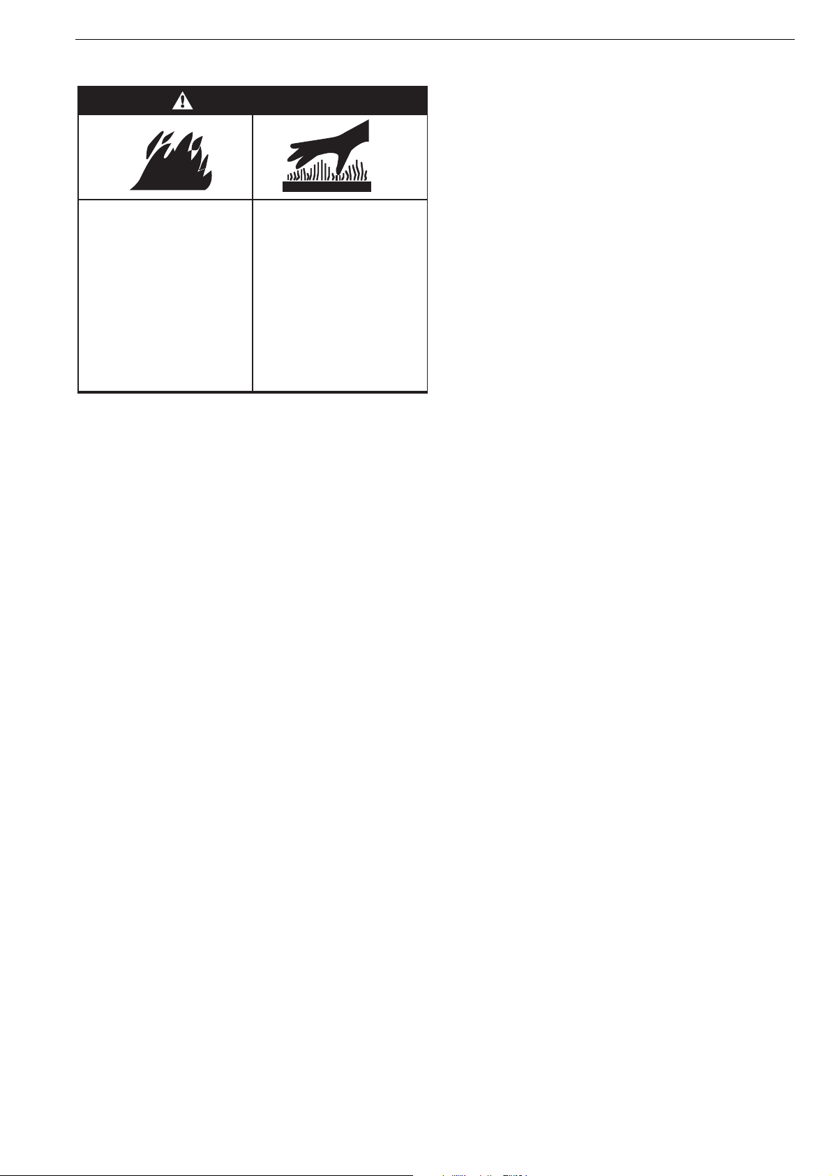
WARNING
SECTION 3: CRITICAL CONSIDERATIONS
Fire Hazard
Some objects will catch fire
or explode when placed
close to heater.
Keep all flammable objects,
liquids and vapors the
minimum required
clearances to combustibles
away from heater.
Failure to follow these
instructions can result in
death or injury.
3.1 Minimum Required Clearances to Combustibles
Clearances are the required distances that combustible
objects must be kept away from the heater to prevent
serious fire hazards. Combustibles are materials, which
may catch on fire and include common items such as
wood, paper, rubber, fabric, etc. Maintain clearances to
combustibles at all times for your safety.
Clearances for all heater models are located on Page 4,
Figure 2 through Page 7, Figure 15 in this manual. Check
the clearances on each burner for the model heater being
installed to make sure the product is suitable for your
application and the clearances are maintained. Read and
follow the safety guidelines below:
• Keep petrol or other combustible materials including
flammable objects, liquids, dust or vapours away from
this heater or any other appliance.
• Maintain clearances from heat sensitive material,
equipment and workstations.
• Maintain clearances from vehicles parked below the
heater.
• Maintain clearances from swinging doors, overhead
cranes, vehicle lifts, partitions, storage racks, hoists,
etc.
• In locations used for the storage of combustible
materials, signs must be posted to specify the
maximum permissible stacking height to maintain
required clearances from the heater to the combustibles. Signs must be posted adjacent to the heater
thermostat. In the absence of a thermostat, signs
must be posted in a conspicuous location.
• Consult local Building Inspector, Fire Insurance
Carrier or other authorities for approval of proposed
installation when there is a possibility of exposure to
combustible airborne materials or vapours.
• Hang heater in accordance to the minimum suspension requirements on Page 9, Section 4.6 through
Page 9, Section 4.8.
• If the radiant tubes must pass through the building
structure, be sure that adequate sleeving and fire
stop is installed to prevent scorching and/or fire
hazard.
Burn Hazard
Keep all persons,
especially children, away
from heater.
Do not touch any part of
the heater.
Heater is very hot.
Failure to follow these
instructions can result in
severe injury.
3
Page 6
BLACKHEAT® INSTALLATION OPERATION AND SERVICE MANUAL
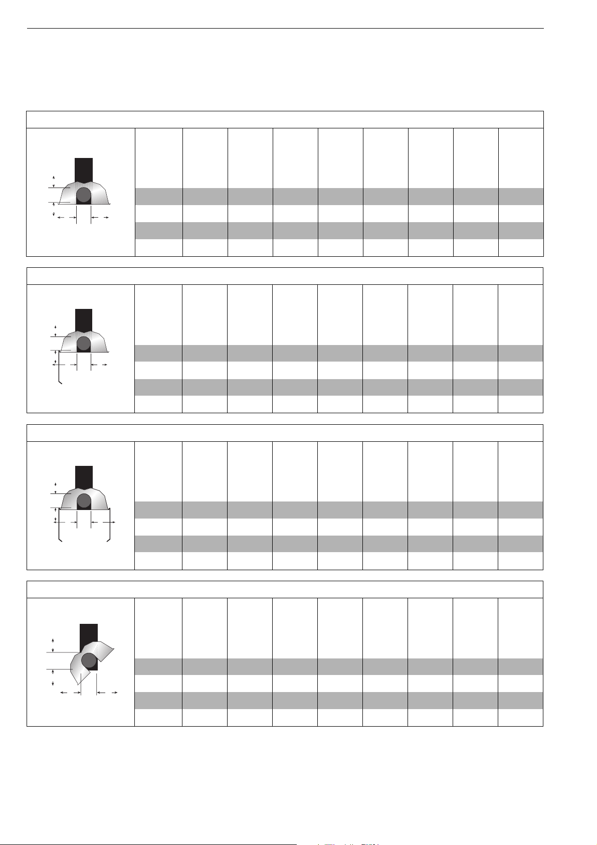
3.2 Clearance Data -
NOTE: 1. All dimensions are from the Tube surface.
2. Clearances B, C and D can be reduced by 50% after 7 m of tubing downstream
from the burner.
3. All measurements are in Millimeters.
FIGURE 2: LINEAR , HORIZONTAL MOUNTS
A
Model
BH15
BH20
A 150 150 150 150 150 150 200 200
C
B
D
B 890 970 970 1020 1170 1220 1280 1330
C 1570 1650 1650 1780 1930 1970 2010 2080
D 890 970 970 1020 1170 1220 1280 1330
FIGURE 3: LINEAR , ONE SIDE REFLECTOR
A
C
B
D
Model
BH15
A 150 150 150 150 150 150 200 200
B 230 230 230 230 230 230 230 230
C 1580 1760 1760 1930 2090 2130 2160 2240
D 1200 1380 1380 1500 1660 1710 1760 1860
BH20
FIGURE 4: LINEAR, TWO SIDE REFLECTORS
BH25
BH25
BH30
BH30
BH35
BH35
BH40
BH40
BH45
BH45
BH50
BH50
A
Model
C
B
D
A 150 150 150 150 150 150 200 200
B 590 640 640 690 820 860 890 1020
C 1660 1810 1810 1960 2110 2160 2210 2320
D 590 640 640 690 820 860 890 1020
FIGURE 5: LINEAR, 45° MOUNT
A
C
B D
Model
A 200 200 200 250 250 275 300 300
B 200 200 200 200 200 200 200 200
C 1500 1660 1660 1860 1960 2030 2110 2160
D 1370 1520 1520 1630 1750 1820 1880 2000
BH15
BH15
BH20
BH20
BH25
BH25
BH30
BH30
BH35
BH35
BH40
BH40
BH45
BH45
BH50
BH50
4
Page 7
NOTE: 1. All dimensions are from the Tube surface.
A
B
C
D
A
B
C
D
Radiant tubes
Fan
Unvented
Vented
E
F
2. Clearances B, C and D can be reduced by 50% after 7 m of tubing downstream
from the burner.
3. All measurements are in Millimeters.
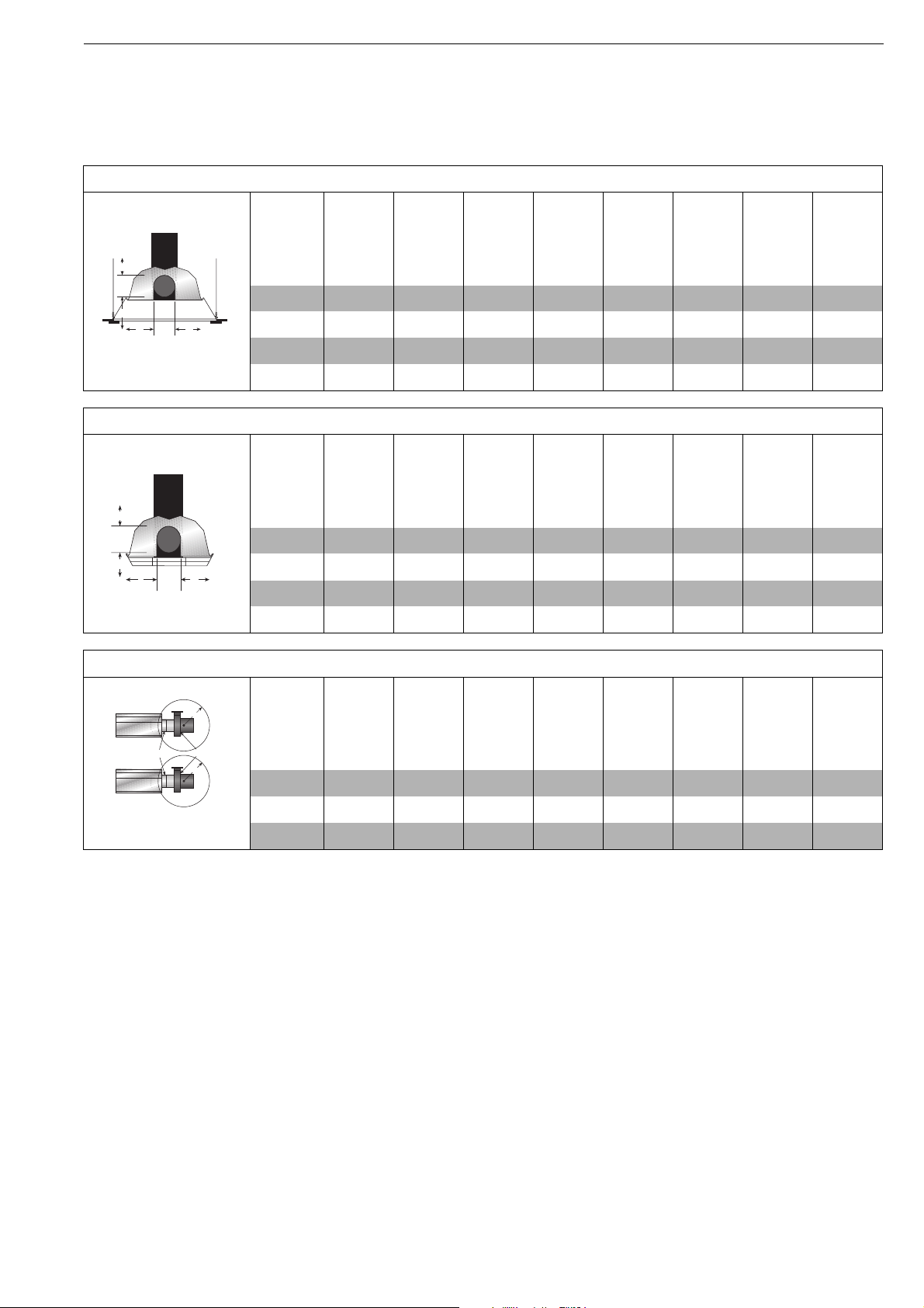
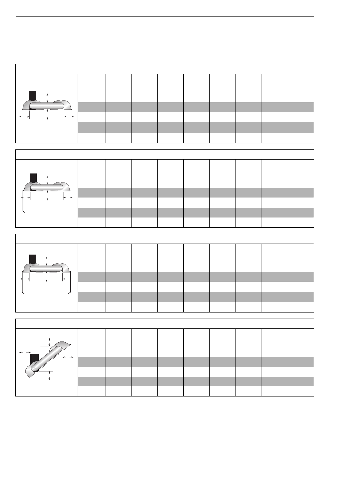
FIGURE 6: LINEAR , 1 FOOT AND 2 FOOT DECO GRILLE
SECTION 3: CRITICAL CONSIDERATIONS
Model
BH15
A 150 150 150 150 150 150 200 200
B 890 970 970 1020 1170 1220 1280 1330
C 1570 1650 1650 1780 1930 1970 2010 2080
D 890 970 970 1020 1170 1220 1280 1330
FIGURE 7: LINEAR , PROTECTIVE GRILLE
Model
A 150 150 150 150 150 150 200 200
B 890 970 970 1020 1170 1220 1280 1330
C 1570 1650 1650 1780 1930 1970 2010 2080
D 890 970 970 1020 1170 1220 1280 1330
BH15
FIGURE 8: LINEAR , VENTING
BH20
BH20
BH25
BH25
BH30
BH30
BH35
BH35
BH40
BH40
BH45
BH45
BH50
BH50
Model
BH15
BH20
BH25
BH30
BH35
BH40
BH45
BH50
E 1000 1000 1000 1000 1000 1000 1000 1000
F 500 500 500 500 500 500 500 500
5
Page 8
BLACKHEAT® INSTALLATION OPERATION AND SERVICE MANUAL
3.3 Clearance Data -U Tube
NOTE: 1. All dimensions are from the Tube surface.
2. Clearances B, C and D can be reduced by 50% after 7 m of tubing downstream
from the burner.
3. All measurements are in Millimeters.
.
FIGURE 9: U-TUBE, HORIZONTAL MOUNT
A
Model
BH15
BH20
A 150 150 150 150 150 150 200 200
C
DB
B 890 970 970 1020 1170 1220 1270 1380
C 1580 1730 1730 1910 1980 2050 2110 2210
D 760 940 940 1000 1090 1150 1200 1300
FIGURE 10: U-TUBE, ONE SIDE REFLECTOR
A
B
C
D
Model
BH15
BH20
A 150 150 150 150 150 150 200 200
B 230 230 230 230 230 230 230 230
C 1580 1760 1760 1930 2090 2130 2160 2240
D 1200 1380 1380 1500 1660 1710 1760 1860
FIGURE 11: U-TUBE, TWO SIDE REFLECTORS
A
Model
C
DB
A 150 150 150 150 150 150 200 200
B 590 640 640 690 820 860 890 1020
BH15
BH20
BH25
BH25
BH25
BH30
BH30
BH30
BH35
BH35
BH35
BH40
BH40
BH40
BH45
BH45
BH45
BH50
BH50
BH50
C 1660 1810 1810 1960 2110 2160 2210 2320
D 590 640 640 690 820 860 890 1020
FIGURE 12: U-TUBE, FULL 45° MOUNT
A
B
D
C
Model
BH15
A 200 200 200 200 200 200 200 200
B 200 200 200 200 200 200 200 200
C 1500 1650 1650 1860 1960 2040 2110 2160
D 1070 1170 1170 1320 1550 1620 1680 1780
BH20
BH25
BH30
BH35
BH40
BH45
BH50
6
Page 9

NOTE: 1. All dimensions are from the Tube surface.
A
C
B D
A
C
DB
Radiant tubes
Fan
Unvented
Vented
E
F
2. Clearances B, C and D can be reduced by 50% after 7 m of tubing downstream
from the burner.
3. All measurements are in Millimeters.
FIGURE 13: U-TUBE, OPPOSITE 45° TILT
SECTION 3: CRITICAL CONSIDERATIONS
Model
BH15
A 200 200 200 250 250 275 300 300
B 1370 1530 1530 1630 1780 1830 1880 1930
C 1500 1650 1650 1860 1960 2040 2110 2160
D 560 560 560 560 560 560 560 560
FIGURE 14: U-TUBE, PROTECTIVE GRILLE
Model
A 150 150 150 150 150 150 200 200
B 890 970 970 1020 1170 1220 1270 1380
C 1580 1730 1730 1910 1980 2050 2110 2210
D 760 940 940 1000 1090 1150 1200 1300
BH15
FIGURE 15: U-TUBE, VENTING
BH20
BH20
BH25
BH25
BH30
BH30
BH35
BH35
BH40
BH40
BH45
BH45
BH50
BH50
Model
BH15
BH20
BH25
BH30
BH35
BH40
BH45
E 1000 1000 1000 1000 1000 1000 1000 1000
F 500 500 500 500 500 500 500 500
BH50
7
Page 10

BLACKHEAT® INSTALLATION OPERATION AND SERVICE MANUAL
SECTION 4: SPECIFICATIONS
4.1 Material Specifications
4.3 Venting Specifications
4.1.1 Combustion and Tubes
First 3 meters ALUMI-THERM
®
steel tubing.
Remaining tube 100 mm dia. 16 gauge heat treated
aluminised mild steel.
4.1.2 Reflectors
NS3 H14 aluminium or 1.4016 2R stainless
steel (option)
4.2 Heater Specifications
4.2.1 Sequence Controller
Fully automatic single try direct spark 100% shut off
ignition flame rectification module
4.2.2 Electrical
Rating: 230V, 50 Hz, single phase, 1 amp
Connection: 3 pin moulded plug
4.2.3 Gas Supply
Connection: Rc1/2 (1/2" BSP int)
Natural : Nominal - Inlet 1.13kPa
Maximum - Inlet 5.0 kPa
4.3.1 Fans
BH-15, 20, 25, 30 ............ Model: Torin DSF 133-42
BH-35, 40, 45 .................. Model: Torin DSA 524-202
BH-50 .................. Model: Magnetek JF1G
Consult the manufacturer for availability of alternate fans.
4.3.2 Flue
When fitted, the flue must be 100 mm, or greater in
diameter, and must conform to AS5601/AG 601. The flue
must be self supporting. Inlet must be 100 mm diameter.
4.4 Suspension Specifications
Galvanised straight link welded chain.
Working load of 340 kg (750 lbs)
4.5 Controls Specifications
Time switches, thermostats, etc. can be wired into the
electrical supply. External controls supplied as an
optional extra.
ULPG Gas (Propane or Propane/Butane mix):
Nominal - Inlet 2.75 kPa
Maximum - Inlet 5.00 kPa
8
Page 11

-----------------------------------------------------------------------------------------------------------------------------------------------------------------------------------
SECTION 4: Specifications
4.6 Linear Heater
BH15ST
BH20ST
BH25ST
BH30ST
BH35ST
BH40ST
BH45ST
BH50ST
Input – kW 15 20 25 30 35 40 45 50
Input – MJ 54 72 90 110 125 138 162 180
Tube Length – mm 6096 9144 9144 12192 12192 12192 15240 15240
Overall Heater Length - mm 6661 9709 9709 12757 12757 12757 15815 15815
Weight – kg 41 55 55 68 68 68 81 81
Heated Area – m
Minimum Installation
2
20-160 30-210 40-265 50-315 55-370 65-420 70-475 80-525
2.5 2.5 3.0 3.5 4.6 5.0 5.0 5.0
Height* – m
Recommended Installation
3.0 3.5 3.9 4.2 4.8 5.5 6.7 7.6
Height* – m
4.8 U-Tube Heater
BH15UT
BH20UT
BH25UT
BH30UT
BH35UT
BH40UT
BH45UT
BH50UT
Input – kW 15 20 25 30 35 40 45 50
Input – MJ 54 72 90 110 125 138 162 180
Tube Length – mm 3323 4843 4843 6363 6363 6363 7998 7998
Overall Heater Length - mm 3893 5417 5417 6941 6941 6941 8465 8465
Weight – kg 39 54 54 65 65 66 96 96
Heated Area – m
Minimum Installation
2
20-160 30-210 40-265 50-315 55-370 65-420 70-475 80-525
2.5 2.8 3.5 4.0 5.0 5.0 5.0 5.0
Height* – m
Recommended Installation
3.0 3.5 3.9 4.2 4.8 5.5 6.7 7.6
Height* – m
*Heights quoted are from ground level to bottom face of firing tube.
NOTE:- Factory recommended mounting height s are listed above as a guideline. If infra-red heaters are
mounted too low, they may result in heat discomfort. It is generally recommended to observe the
recommended mounting heights to optimize comfort conditions. However, certain applications such as spot
heating, freeze protection, outdoor patio heating or very high ceilings may result in the heaters being
mounted outside of the factory recommended mounting heights. Clearances to combustibles must always be
maintained.
Page 12

BLACKHEAT® INSTALLATION OPERATION AND SERVICE MANUAL
4.9 Burner Specifications
Figure 16: BLACKHEAT® Linear and U-Tube
Reflector
317 mm
Plan View
Burner Tube
Side View
273 mm
End View
171 mm
100 mm
Heat Exchanger Length
Fan
Swirler*
Damper
Heat Exchanger Length
U-Tube
Burner Tube
Fan Tube
Fan
Damper
Plan View
100 mm
Internal Swirler*
*Swirler must always be located in Fan Tube
4.9.1 Burner Air Plate BH15 BH20 BH25 BH30 BH35 BH40 BH45 BH50
Marking 071300+ 20 15 12 06 07 09 11 10
4.9.2 Jet Marking BH15 BH20 BH25 BH30 BH35 BH40 BH45 BH50
Natural #30 3.8 mm #19 4.7 mm #9 #3 #1 D
Propane/Butane #46 2.3 mm #37 #33 3.1 mm 3.3 mm #29 #26
4.9.3 Gas Consumption BH15 BH20 BH25 BH30 BH35 BH40 BH45 BH50
Natural
[MJ/hr]
54 72 90 110 125 138 162 180
ULPG MJ/hr as Natural Gas. Approximate kg/h consumption as below for reference only.
[kg/h]
[1.07] [1.43] [1.79] [2.15] [2.50] [2.86] [3.22] [3.58]
4.9.4 Governor Pressure BH15 BH20 BH25 BH30 BH35 BH40 BH45 BH50
ULPG All Models 2.60 kPa
Natural Gas All Models 0.75 kPa
10
Page 13

SECTION 5: MAJOR COMPONENT DESCRIPTIONS
Burner (shown with T ube
Gasket)
Must be installed with the
flame observation window
facing down.
Reflector
(Alum inium or
Stainless Steel)
Alternate overlap as
shown on overview.
Minimum overlap is 18
cm.
SECTION 5: MAJOR COMPONENT DESCRIPTIONS
Burner Tu be
Supplied in 3m lengths. Burner
tube is always the first tube after
the burner.
Tube and Reflector Hanger
with Tube Clamp Package
Position this hanger no more
than 20cm away from the
burner assembly.
Recommended 100mm.
Tu be a n d R ef lector Hanger
Suspend system from these
hangers.
Reflector S upport Strap, W ir e
Form & #8 x 3/4 (3.9 x 19mm)
Screw
Flex Gas Line
Tube
Heat Treated Aluminized Tube
Supplied in 3m lengths.
Fan Tube with In ternal Swirler
Fan tube is
always the last tube on the heater
where the fan is attached.
Coupling A s sembly
with Lock
Reflector End Cap
Punch out center section to
accommodate heat exchanger
tube.
Fan Assembly (Includes Flange)
Fan Assembly is attached to the last
section of heat exchanger tubing
(Fan Tube).
Damper Flange Assembly
For use on Multiburner Systems.
Tee
Assembly
U-Tube
Assembly
U-Tub e
Support
Bracket
Fan Flange Assembly
and Screws
Turnbuckle
Adjuster
Bow
Shackle
11
Page 14

BLACKHEAT® INSTALLATION OPERATION AND SERVICE MANUAL
SECTION 6: GENERAL SUSPENSION DETAILS
WARNING
Suspension Hazard
Hang heater with general purpose welded link steel
chain, 4 mm or larger in diameter, with working
load of 340 Kg.
Failure of the supports can result in death, injury
or property damage.
Step 6.1 Suspension Details
Side View
Typical Suspension Details
Beam
Clamp
I-Beam
60 cm
minimum*
Turnbuckle
(not included)
I-Beam
10 mm
Rod
30 cm
minimum*
* Allows for thermal expansion of system
Bow Shackle
Concrete
Beam
Anchor
Bow
Shackle
Screw Hook
min. 10 mm
Washer
Locknut
Washer
Wood
Beam
Hanger
100 mm
Max.
Description Part Number
Burner Tube 03051101
Bow Shackle E0007576
Tube/Reflector Hanger 03090100
12
Hanger
Front View
45° Angle
Page 15

SECTION 7: LINEAR HEATER INSTALLATION
The figures in this section provide a general overview of
component placement in a BLACKHEAT® Linear
system. The location of some components
such as supports and couplings is crucial for proper
installation. Assemble the heater components as shown
on Page 14, Figure 17.
7.1 Linear Standard Parts List
SECTION 7: LINEAR HEATER INSTALLATION
For optional reflector configurations for Linear heaters
See Page 4, Figure 2 through Page 5, Figure 8. Install
appropriate suspension hardware, beam clamps, chain or
rod at predetermined locations. Adjustments of chain
length will provide uniform pitch.
If any step is unclear, please contact Roberts-Gordon at
+ 61 [3] 9561 2100 [Hurll Nu-Way Pty Ltd]
Part No. D escriptio n
BLACKHEAT®
07260001 Fan Package XP 1 1 1 1 1 - - - 07260002 Fan Package XP 2 - - - - 1 1 1 07260003Fan Package XP 3 -------1
03051101Burner Tube, 100 mm x 3048 mm 11111111
91409408Tube, 100 mm x 3048 mm -1122233
S5127WFan Tube, 100 mm x 3048 mm, with 3048 mm Swirler 1111111
S5134WFan Tube, 100 mm x 3048 mm with 2134 mm Swirler -------1
01329600Standard Coupling Assembly 12233344
01329700Coupling Lock 12233344
02750303Reflector, Aluminium, 2439 mm 34466677
S5163WReflector, Stainless Steel, 2439 mm (Optional)* 34466677
02750800Reflector End Cap, Aluminium 22222222
C2332B Reflector End Cap, Stainless (Optional)* 2 2 2 22222
Burner Assembly (Input and Fuel Varies)11111111
BH15
BH20
BH25
BH30
BH35
BH40
BH45
BH50
03090100Tube and Reflector Hanger 34455566
01318901 Tube Clamp Package (including Nut, Washer & Bolt) 1 1 1 11111
91908004Wire Form 23355566
94320812 Screw #8 x 3/4 (3.9 x 19mm), (goes with 91908004) 4 6 6 10 10 10 12 12
03050000Reflector Support Strap 23355566
E0007576 Bow Shackle 3 4 4 55566
91107720 U-Clip Package (20 Pieces) 1 1 1 11111
* PVC coating must be removed prior to installation.
13
Page 16

BLACKHEAT® INSTALLATION OPERATION AND SERVICE MANUAL
Figure 17: BLACKHEAT® Linear General Assembly Overview
U-Clips
Fan Assembly
(For Single Heater)
Damper Assembly
(Required for Multiburner)
Reflector
Internal Swirler
Fan Tube
Reflector Support
Coupling
14
Reflector End Cap
Burner Tube
Tube and Reflector Hanger
Burner
Tube Clamp Package
Page 17

SECTION 7: LINEAR HEATER INSTALLATION
Reflector
Figure 18: BLACKHEAT® Linear Layout Overviews -[BH55 Not Available]
b
c
BH15ST
b
c
g
f
de
LEGEND
Burner Box
Reflector
BH20ST
BH25ST
BH30ST
BH35ST
BH40ST
BH45ST
BH50ST
*Loose
Screw
b
c
g
f
g
f
g
de
*Loose
Screw
b
c
de
*Loose
Screw
b
c
de
Tight
Screw
Tight
Screw
Tight
Screw
*Loose
Screw
*Loose
Screw
e
e
Screw
e
Tight
b
c
*Loose
Screw
b
c
e
b
c
e
e
Tube
Tube/Reflector
Hanger
Reflector Support
Coupling Assembly
Fan Assembly
Damper Assembly
*Loose Screws -
f
loosened
2 mm (1/16")
to allow slippage.
*Loose
Screw
b
c
g
de
Screw
Tight
*Loose
Screw
*Loose
Tight
Screw
Screw
e
e
Tight
Screw
b
c
e
e
BH55ST
Model
BH15
BH20..
BH25
BH30..
BH35
BH40..
BH45
BH50..
BH55
f
*Loose
Screw
Tight
Screw
a = reflector width (not shown)
b = end cap to burner/fan
c = end cap to hanger
*Loose
Screw
Tight
Screw
*Loose
Screw
Tight
Screw
*Loose
Screw
e = distance typical between hangers
f = burner height
g = burner length
d = distance first hanger
Reflector
Overlap
(approx.) a b c d e f g
700 mm 365 mm 50 mm 50 mm 2290 mm 3050 mm 366 mm 291 mm
250 mm 365 mm 50 mm 50 mm 2290 mm 3050 mm 366 mm 291 mm
250 mm 365 mm 50 mm 50 mm 2290 mm 3050 mm 366 mm 291 mm
530 mm 365 mm 50 mm 50 mm 2290 mm 3050 mm 366 mm 291 mm
530 mm 365 mm 50 mm 50 mm 2290 mm 3050 mm 366 mm 291 mm
530 mm 365 mm 50 mm 50 mm 2290 mm 3050 mm 366 mm 291 mm
330 mm 365 mm 50 mm 50 mm 2290 mm 3050 mm 366 mm 291 mm
330 mm 365 mm 50 mm 50 mm 2290 mm 3050 mm 366 mm 291 mm
200 mm 365 mm 50 mm 50 mm 2290 mm 3050 mm 366 mm 291 mm
15
Page 18

Step 7.3 Burner Tube Installation
SECTION 7: LINEAR HEATER INSTALLATION
NOTE:
Tubing requires a downward
slope of 13 mm
per 6 m away
from burner.
Bow Shackle
Hanger
Burner Tube
229 cm ± 25cm
Description Part Number
Burner Tube 03051101
Bow Shackle E0007576
Tube/Reflector Hanger 03090100
Weld
Seam
End View
Offset mounting
hole must be
to the top
Bottom
of Tube
Step 7.4 Coupling and Tube Assembly
Close coupling
A
with tab
Open
Closed
Insert tubes into coupling
C
Orient coupling so that
the impact block is in the
2:00 or 10:00 oclock
positions
Tab
Start Slidebar/Coupling Lock
B
onto coupling
Slidebar
8 cm to
10 cm
Tighten coupling to join tubes
D
Wide end
Coupling
Slidebar
Coupling
Tube
Tube
Tube
Description Part Number
Coupling 01329600
Slidebar/Coupling Lock 01329700
Tube 91409408
19
Page 19

BLACKHEAT® INSTALLATION OPERATION AND SERVICE MANUAL
Step 7.4.1 Coupling and Tube Assembly (Continued)
WARNING
Tighten slidebar as shown below.
Tubes will fall down if slidebar is incorrect.
Failure to follow these instructions can result in death,
injury or property damage.
Drive Slidebar until tight.
End of slidebar should be
within tolerance listed below.
± 5 cm
Correct slidebar
dimensions
Incorrect slidebar
position
• Repeat Step 7.4 A - D until all tubes are assembled, See Page 20, Section 7.4.2 shown bel ow.
Step 7.4.2 Coupling and Tube Assembly (Continued)
Model
BH15 6 2
BH20 9 3
BH25 9 3
BH30 12 4
BH35 12 4
BH40 12 4
BH45 15 5
BH50 15 5
229 cm
± 25 cm
Heat Exch anger
Overall Tubing Length (m)
Number
of Tubes
20
305 cm Typ
± 25 cm
Total Overall
Tube Length
Page 20

Step 7.5 Tube Clamp Package Installation
Tube Clamp
SECTION 7: LINEAR HEATER INSTALLATION
Bolt
Description Part Number
Tube Clamp 01396801
Bolt 97113940
Flat Washer 95211600
Nut 92113900
Step 7.6 Reflector Installation
Nut
(Torque 13.56 Nm
120 in lb)
Flat
Washer
Hanger
Burner Tube
Description Part Number
Tube/Reflector Hanger 03090100
Burner Tube 03051101
Reflector 02750303
Reflector
21
Page 21

BLACKHEAT® INSTALLATION OPERATION AND SERVICE MANUAL
Reflector
Reflector
Step 7.6.1 Reflector Installation (Continued)
Reflector
End Cap
U-Clips
Description Part Number
Reflector Support Package 03050010
Wire Form 91908004
Reflector Support Strap 03050000
Screw #8 x 3/4 (3.9 x 19mm) 94320812
U-Clip Package 91107720
Reflector End Cap 027508XX
Wire Form
Reflector
Reflector Support
Strap
U-Clip
(2 clips per alternate
overlaps per side-
see Figure 21)
Sheet Metal
Screw
Tube
Figure 21: Reflector Overlap Detail
Loose screws
loosened 2 mm (1/16")
to allow slippage.
Tight
screws
Install one reflector
support per reflector
as needed.
No
U-Clips
Tight
screws
Install
U-Clips
Loose
screws
No
U-Clips
18 cm (7")
Minimum
Install
U-Clips
18 cm (7")
Minimum
22
Page 22

BLACKHEAT® INSTALLATION OPERATION AND SERVICE MANUAL
SECTION 8: U-T UBE HEATER INSTALLATION
The figures in this section provide a general overview of
component placement in a BLACKHEAT® U-Tube
system. The location of some components such as
supports and couplings is crucial for proper installation.
Assemble the heater components as shown on Page 14,
Figure 17.
For optional reflector configurations for U-tube heaters
See Page 6, Figure 9 through Page 7, Figure 15. Install
8.1 U-Tube Standard Parts List
appropriate suspension hardware, beam clamps, chain or
rod at predetermined locations. Adjustments of chain
length will provide uniform pitch.
If any step is unclear, please contact Roberts-Gordon at
+44 (0) 1902 494425 or +61 [3] 9561 2100
Part No. Descr iption
BLACKHEAT®
0726000 1 Fan Package XP1 1 1 1 1 - - - 0726000 2 Fan Package XP2 - - - - 1 1 1 0726000 3 Fan Package XP3 - - -----1
03051101Burner Tube, 100 mm x 3048 mm 11111111
9140940 8 Tube, 100 mm x 3048 mm - - - 2 2 2 2 2
9140942 3 Tube, 100 mm x 1524 mm - 2 2 - - - 2 2
S5127WFan Tube, 100 mm x 3048 mm, with 3048 mm Swirler 1111111
S5134WFan Tube, 100 mm x 3048 mm with 2134 mm Swirler -------1
01335901U-Bend 11111111
01329600Standard Coupling Assembly 24444466
01329700Coupling Lock 24444466
02750303Reflector, Aluminium, 2439 mm 44466688
S5134W Reflector, Stainless Steel, 2439 mm (Optional)* 4 4466688
Burner Assembly (Input and Fuel Varies) 11111111
BH15
BH20
BH25
BH30
BH35
BH40
BH45
BH50
02750800Reflector End Cap, Aluminium 44444444
C2332B Reflector End Cap, Stainless (Optional )* 4 4444444
03090100Tube and Reflector Hanger 46666688
0131890 1 Tube Clamp Package (including Nut, Washer & Bol t ) 1 1111111
91908004Wire Form 24444466
03050000Reflector Support Strap 24444466
0302050 1 U-Bend Support Bracket 1 1111111
E000757 6 Bow Shackle 4 6666688
91107720 U-Clip Package (20 Pieces) 2 2222222
91912501U-Bolt M6 22222222
C0090BNut M6 66666666
96411500Lockwasher 6mm 66666666
94320812Screw #8 x 3/4 (3.9 x 19mm), (goes with 91908004) 4888881212
S7199K Damper Flange Assembly (For use on Multib urner Systems) 1 Per Heater
*PVC coating must be removed prior to installation.
24
Page 23

Figure 22: BLACKHEAT® BH15UT Assembly Overview
SECTION 8: U-TUBE HEATER INSTALLATION
U-Clips
Internal Swirler
Support
Reflector
Fan Tube
Reflector
Reflector End Caps
457 mm
180° U-Tube
Center to Center
Fan Assembly
(For Single Heater)
Damper Assembly
(Required for Multiburner)
Tube Clamp
Burner
20cm
Maximum
Package
Coupling
Burner Tube
U-Tube
Support Bracket
25
Page 24

BLACKHEAT® INSTALLATION OPERATION AND SERVICE MANUAL
Reflector
Figure 23: BLACKHEAT® U-Tube Layout Overviews
b
c
g
d
LEGEND
Burner Box
BH15
BH20
BH25
BH30
BH35
BH40
h
*Loose
Screw
b
c
g
df
h
*Loose
Screw
b
c
g
de
h
Tight
Screw
*Loose Screws -
Reflector
Tube
Tube/Reflector
Hanger
Reflector Support
Coupling Assembly
U-Tube
loosened
2 mm (1/16")
to allow slippage.
*Loose
Screw
b
c
g
de
Tight
Screw
f
BH45
BH50
a = overall width (not shown)
b = end cap to burner/fan
c = end cap to hanger
Reflector
Overlap
Model
BH15
BH20 ....
BH25
BH30....
BH35
BH40....
BH45
BH50....
(approx.) a b c d e f g
1780 mm 850 mm 50 mm 50 mm 2290 mm 3050 mm 366 mm 291 mm
250 mm 850 mm 50 mm 50 mm 2290 mm 3050 mm 366 mm 291 mm
250 mm 850 mm 50 mm 50 mm 2290 mm 3050 mm 366 mm 291 mm
580 mm 850 mm 50 mm 50 mm 2290 mm 3050 mm 366 mm 291 mm
580 mm 850 mm 50 mm 50 mm 2290 mm 3050 mm 366 mm 291 mm
580 mm 850 mm 50 mm 50 mm 2290 mm 3050 mm 366 mm 291 mm
690 mm 850 mm 50 mm 50 mm 2290 mm 3050 mm 366 mm 291 mm
690 mm 850 mm 50 mm 50 mm 2290 mm 3050 mm 366 mm 291 mm
h
*Loose
Screw
Tight
Screw
d = distance first hanger
e = distance typical between hangers
*Loose
Screw
g = burner length
h = burner height
f = distance between last full tube
hanger and half tube hanger
26
Page 25

Step 8.2 Critical Hanger Placement
Spreader
Bow
Shackle
Suspension
Chain
Washers
Bolt
(Torque:
13.5 Nm
129 in lb)
Configuration
Bar
Threaded
Optional
Hanging
Bar
Tube and Reflector
Hanger
SECTION 8: U-TUBE HEATER INSTALLATION
NOTE: Spreader bar must be used on
single suspension point installations.
Do not hang heater from spreader bar.
Bow
Shackle
Suspension
Chain
First Tube and
Reflector Hanger
229 cm ± 25cm
Description Part Number
Bow Shackle E0007576
Tube/Reflector Hanger 03090100
Spreader Bar 07260010
Step 8.3 Burner Tube and Fan Tube Installation
See Assembly
Drawing
End View
Tube and Reflector
Hanger
Offset mounting
hole must be
to the top
Burner Tube
Description Part Number
Burner Tube 03051100
Fan Tube S5127W
Fan Tube
Weld
Bottom
of Tube
27
 Loading...