

Page 1
PnoTo FAcr'
FolJ"t
ro
Et
o€
-t
OE
rJ,
vl
ROBERTS
MODET
I92FT
(G
O.,
I N G.
tndianapotis
€i, tndianaHCDWARD
W.
SAlYlS
&
The listing
of any available
replacement
part
herein
does not
constitute
in any
case a recommendation,
warranty or
guaranty
by Howard W. Sams & Co.,
Inc., as
to
the
quality
and suitability
of
such replacement
part.
The
numbers of these
parts
have
been
compiled from information
furnished
to Howard W.
Sams & Co.,
Inc.,
by
the manufacturers of the
particular
type
of
replacement
cQ5i4
F
lr
lnol
l-
O\
l-
lr|
6E
4g
E
3
Ot
E9
'm
tF
€{
}\'ln
llt
{
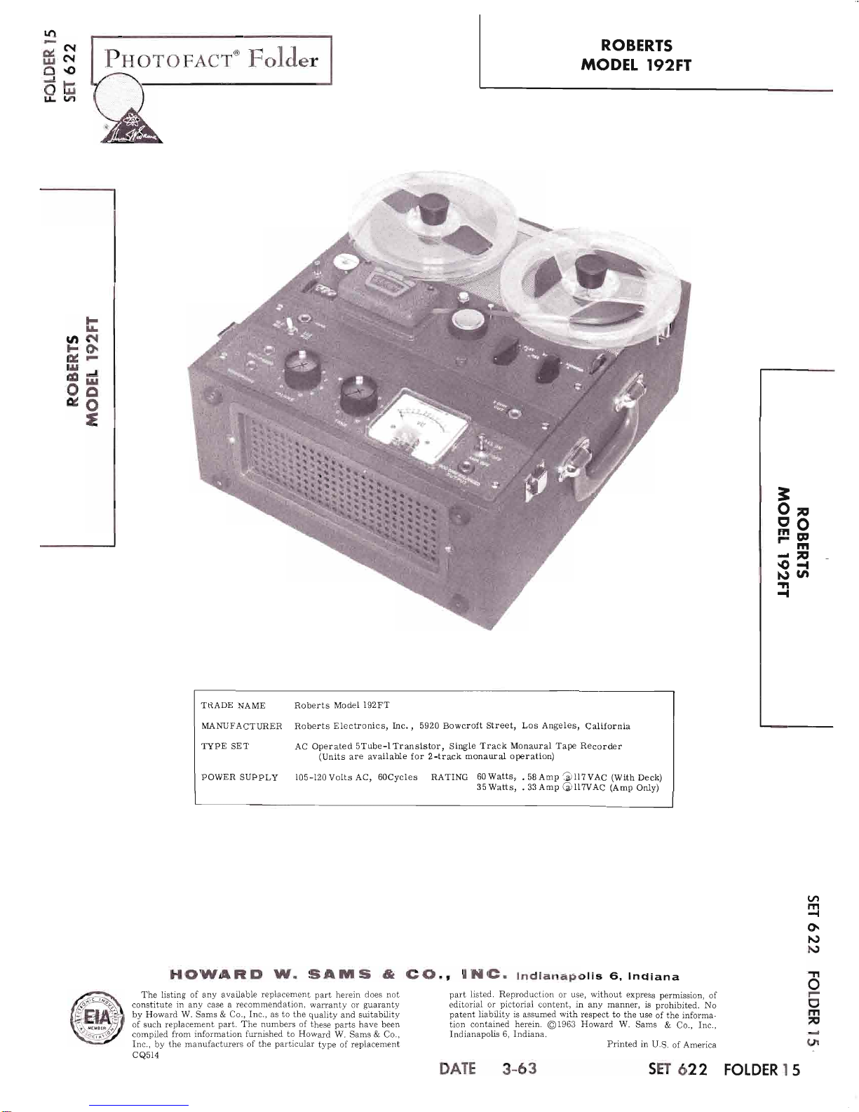
TRADE
NAME
Roberts
Model
192FT
MANUFACTIIRER
Roberts
Electronics,
Inc.
,
5920 Bowcroft
Street,
Los
Angeles,
California
TYPE SET
AC Operated
STube-lTranslstor, Single
Track
Monaural
Tape
Recorder
(Units
are
available for
2-track monaural operation)
powER
suppl,y
I05-I20volts AC,
60Cycles RATING
60watts,
.58Amp'oUTVAC
(With
Deck)
35Watts, .33Amp
@ll7vAc
(Amp
Only)
part
listed. Reproduction or use, without express
permission,
of
editorial
or
pictorial
content, in
any
manner,
is
prohibited.
No
patent
liability is
assumed
with
respect to the use of the informa-
tion
contained
herein.
01963
Howard
W. Sams & Co.,
Inc.,
Indianapolis
6, Indiana.
Printed
in U.S. of America
(
m
{
O.
N)
N
TT
o
|-
I
m
F
(Jr
DATE 3-63 SET
622 FOLDER
I 5
Page 2
FRtrOUENCY
RESPONSE:
40
to 15,000
cps
at ? l/2tps
*2
db; 40 to 9,b00
cps
at
3 3/4
ips
+ 3
db.
SIGNAL-
TO.
NOIS E RATIO:
55
db
below
recorded
"0"
Ievel.
WOW AND
FLUTTER:
Les s
than
0. 1B7o rms.
HEADS:
FuIl-track
erase
and
record/playback
in shielded
housing.
SPECIFICATIONS
PREPA
RING
FOR
OPERATION
OUTPUT:
6 watts undistorted.
REEL
SIZE:
?"
maximum
(up
to 2400
ft. of tape).
POWER
REQI]IREMENTS:
95
to 120
volts
AC, 60 cvcles,
50
watts.
SIZE:
15
3/4" xt4 t/2"
xI
t/2".
WEIGHT:
Approx.
28 lbs.
l.
t
Remove lid from carrying
Remove microphone and
storage
compartment
on
case.
case.
AC
supply
cord
from
left side of earrying
3. Make
certain
all controls are in
ttre
neutral
po-
sition.
FUNCTION
OF CONTROLS
0n-Off
Switch
When
the switch is
pushed
to the All-On
posi-
tion,
power
isturned
onto
theamplilier and
tapedeck.
When
the
switch
isin
the Amp-Off
position,
power
is
applied
to the
tape deck
only. The
Of{
position
turns
the
power
off
to
the entire unit.
Volume
Turning
this
control
elockwise
increases
the
volume
during
playback
and
the recording
level when
recording.
Tone
This control functions
in
playback
only. Turn-
ing
theeontrol
clockwise increases
thehigh
frequency
responae
and
turning
the control
counterclockwise
attenuates
the
high frequency
response.
PIay-Record
and
Record
Lock
This
is
a 3-position
eontrol:
Stop, Piay, and
Record.
Turning
this
control
elocknrise
from
the Stop
position,
places
the
unit in play.
Depressing
the
Record
Lock
and
turning
the
control
to the
Record
position
at
the
same
time,
places
the
unit in
Record"
N0TE:
This
control is
interlocked
with
the
Rewind-Forward
control.
It
must
be
in
the
Stop
position
before
the
Rewind-For-
ward
control
can
be
operated.
Rewind-Forward
Turning
this
control
to
the
left
places
the unit
in
the Rewind
model
to
the right
places
the
unit in
Forward
mode
of operation.
NOTE:
This
control
is interlocked
with
the
Play-Record
control.
It
must
be in
the
Stop
position
before
the
play-Record
con-
trol
can
be
operated.
Pause
When
this lever
is raised,
pressure
is
removed
from the
eapstan,
and
the take-up
reel
is
disengaged.
This
permits
spot
editing
and
momentary
stops.
PAGE
2
Page 3
.:, {?'
ttf
i
()
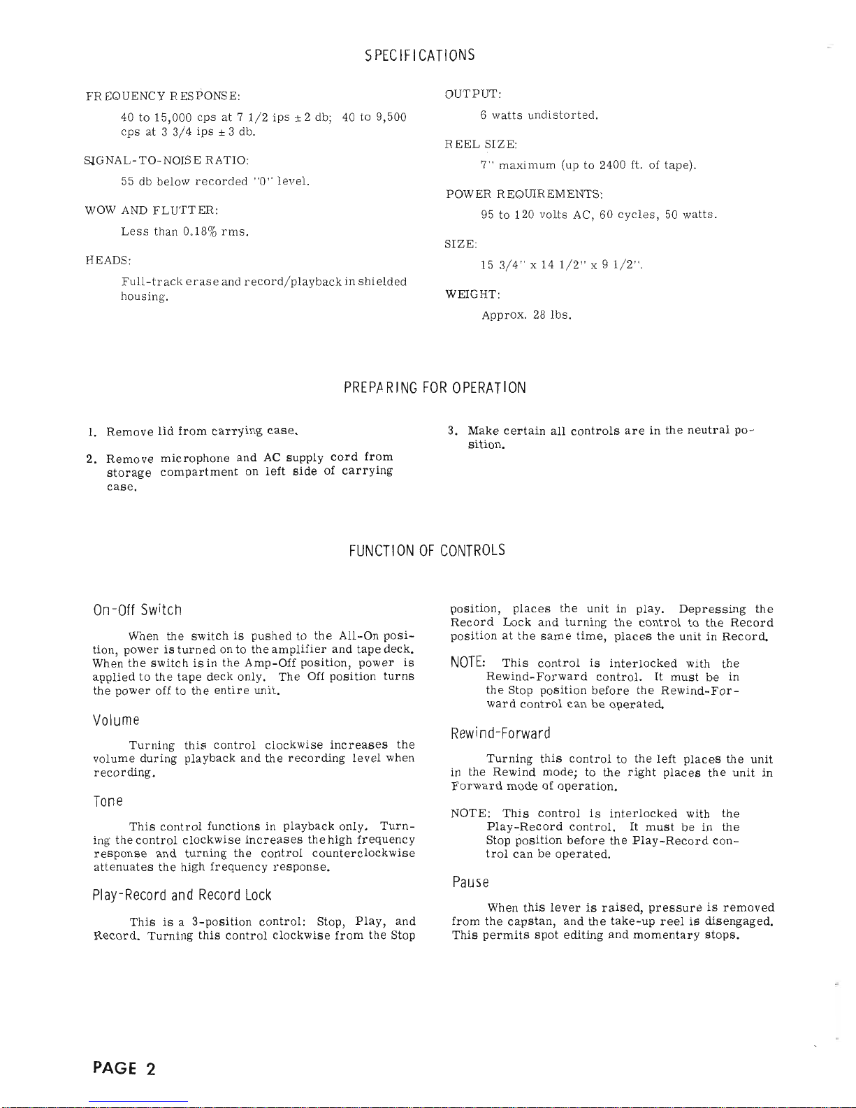
Fig.
l.
TopVieur
of
Tape
Transport
Mechanism.
O
PERATI
NG
I
NSTRUCTIONS
3
Op
E9
'tr
tp
sd
tt
{
Threading the
Tape
1. Place
a
full
reel
of
tape
on the
supply
reel
spin-
dle
(27),
making certain
the
reel
slots
engage
the
protrusions
on the
pan.
Place an
empty
reel
on
the
take-up
spindle
(67),
again
makingcertain
the
slots engage
the
protrusions
on the
pan.
2.
Unwind
about
14
inches
of
tape from
the
supply
reel.
HoId a
section
of
tape
taut
and
insert into
the
tape
slot, making
sure the
dtrll-coated
side
faces
the rear
of the recorder.
3. Insert
the
free
end
of
the
tape
into
one
of
the
slots in
thehub
of the
take-up
reel. While hold-
ing
the
end
in
place,
rotate
the reel
to secure
the
tape and
take
up
any
slack.
To Make
a
Recording
I.
PIug
a microphone
into
the
Microphone
jack.
Place
the High Z iiltric-
Low Z Mic
switch
in
the
proper
position
to match
the
impedance
of
the
microphone.
2.
Plaee
the
Pause lever in
the
Up
positionl
de-
press
the Record
Loek
button and at
the same
time
rotate the
Play-Record
control
to the
Record
position.
3.
Preset
therecording
level
by
adjusting
the
Vol-
ume
control until
the
indicator
goes
up to
the
red
portion
of the
scale
but
does not
enter
the
red
portion
except
on
loud
passages.
CAUTION:
Do not
eonnect
a
speaker
or other
low
impedance
load
to the
Output
jack
while
making a
recording.
To
Play
Back
a
Tape
1.
Thread
the
tape as
described
under
"Threading
the Tape".
2.
Turn
the
unit
on
and
allow
a
few
seconds
for it
to
warm
up.
3.
Turn
the
Play-Record
control
to
play.
4.
Adjust
the
volume
and
tone
to
the desired
list-
ening
level.
Speed Change
To
change
the tape
speed from 7
L/
Z
to B B/
4
ips,
remove
the
thumbscrew
and
bushing
from
the
capstan.
When
the
bushing
is
not
being used,
store
it
on
the
bushing
post.
lndex
Counter
Aftera
tape
is
threadedon
the
recorder,
set the
index
counter
to
"000".
The
index
numbers
ean
then
at
o
F
(f
m
7
J
(lr
PAGE
3
Page 4
-
------.r
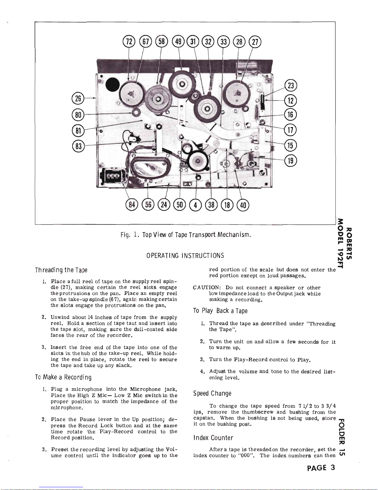
Fig.
2.
Bottom
View of Tape Transport
Mechanisfn.
be
noted at the begindng
of each
selection
for
future
Efasing a Tape
reference'
To eraae
a tape
wlthout
putting
a nev recording
EXtefnal
Speakef
on
it' turn
the Volume control to minlmum
and the
Play-Record
control to
Record"
An external
speaker
may be
plugged
into
the
"B
ohm out"
jack.
ihe
inte"nai speat e-r-vitl
be dis-
To
Record
from a High Signal
Level Source
connected
r hen using
an external apeaker.
To record
from a radio, TV
receiver, or
tuner,
plug
the signal
aource
lnto
the
Rad-Phono
jack.
Use
the
same
recordlng
procedure
aB
de8cribed
under
"To
Record llom
a Microphone".
D ISASSEM BLY
To
Remove Tape Transprt
f rom Case
t.
ffil:l""S:
lour acreq's
holdins the transport
l.
Remove the
two
acren,a
in
the splndle
paDs
(one
ln
each
pan).
8. Unplw
all connectlona
to the tape
transport
and
2.
Remove the tno acrews
holding the dreas
plate
spealrer
and
lift the tranaport
from the case'
and remove the dress
plate.
-
9.
Toereasaemble,
reverae
the foregoing
pro€ed-
3.
Removeone screwon
the rlght side of the
eacut-
cheon and lhe
7 r/2
tps
bustrlng
from the
left
To
Remove
the
Amplifier
from
Case
elde'
I.
Remove four screwa
holdlng
amplifier
and es-
4. Remove the
pressure
roller.
cutcheon
to the ease.
5.
Remove the
Play-Record
and
Rewind-Forward
2. Unplug
all connecting
cablea.
knoba'
3.
Lut the
ampllfier
from the caae.
6'
Remove the eacutcheon'
4. To
reassemble,
revelse
the foregoing
proced-
!e.
PAGE
4
Page 5

Record-
Playback
Head
A
lignment
l.
Thread
a
standard alignment
tape
on
the trans-
port
as described
under
"Threading
the Tape".
2. Connect an
AC
voltmeter to a
standard
phono
plug
and insert
the
plug
into
the
Output
jack.
3.
Remove
the
head
cover.
4.
Insert
ascrewdriverthrough
the
holein
thehead
into
the alignment
screw.
5.
Playthe
tape
back
at full
volume, and
rotate
the
alignment
screw in
either direction
until
the
10,000
cycle note
gives
the highest
meter
read-
ing.
Brake
Shoes
When
brake
shoes
(34)
and
(80)
become
worn,
loosen the mounting
screws
and rotate
the
shoes a few
degrees until a
new
braking
surface
j,s
exposed.
ADJUSTMENTS
LUBRICATION
CLEAN
I
NG
TROUBLE CHART
Lubricate
the
following
parts
every
three
months
in heavy
service,
every
six
months in moderate
ger-
vice,
or
once
a
year
in
light service.
l.
Supply and
take-up reel
spindle shafts, with two
drops of light oil.
2.
Rewind idler
bearing and
take-up idler bearing
with
one
dropof light machine
oil on each bear-
ing.
3.
Apply
a liberal amount
of
light
machine
grease
to the
pressure
roller
bearing
shaft.
Replace
the
pressure
roller and
wipe
a\pay any
excess
grease.
4.
Remove
the thumbscrew
(120)
and?
L/
2 ips
bush:
ing
(l2l)
from the
capstan.
place
a few
diops
of
oil
in the
oil hole in
the capstan
retaining
ring.
Allow the motor
to run for
a few minutes.
Wipe
away any
excess
oil
and replace
the bushing.
5.
Place a
small amount
of
grease
on
the
index
counter
rilorm
gear.
6.
Applya
liberalamountof
machinegrease
to each
roller
on
all
levers and
cams.
7. Disassemble
the motor
and
saturate
the upper
and
lower
oil
pads.
Clean
away
all
excess
oil.
Most
defects, other
than wear
or breakage,
can
be traced
to dirty surfaces with
which
the tape
makes
contaet.
The Record-Playbaek
head,
capstan
and
pressure
roller may accumul,ate
a
coating of residue
which
is worn
off the
tape as it
passes
these
parts.
Usinga
soft cottoncloth
and
aleohol,
clean
theseparts
periodically.
=On
E9
'E
t7l
sd
.ll
{
Sym
ptom
Cause
Remedy
Motor
does
not run.
AC
cord disconnected.
Fuse
blown.
Defective
motor.
Connect AC
cord-
Replace
fuse.
Replace
motor.
I.
2,
3.
t.
2.
3.
Noisy
playback
or
poor
high
frequency
response.
Heads
misaligned.
Head magnetized-
See
"Record-PIayback Head
Alignment".
Demagnetize
head.
i.
2.
l.
2.
Wow or flutter
speed.
at 7j ips
1. Speed change
bushing
(f2l)
slip-
ping
on shaft.
l.
Tighten
screw
(120).
Insufficient
drive
3 3/4 ips
speed.
at 7!
or
l.
2.
3.
4.
Defective main
drive idler wheel
(31).
Oil on capstan.
Defective
capstan
drive belt
(u8).
Drive motor
(I24)
defective.
l. Replace
main
drive idler
wheel
(3t).
See
'Cleaning".
Replace
belt
(ll8).
Replace
drive motor
(124).
2.
3.
4.
Tape spills when
going
from
Rewind
or
Forward
to Stop.
Reel diameters
unequal.
Brake shoes
(34)
and
(80)
worn
or
out of adjustment.
Tape
reels
must have
the same
diameter.
Replace
or
adjust
brake shoes
(3a)
and
(80).
l.
2.
l.
2.
Index
Counter doesnot func-
tion.
l.
Counter belt
(12?)
worn
or bro-
ken.
I" Replace
counter
belt
(127).
No
takeup
or
fast
forpard.
l.
Forward idler
tension
spring
(32)
disconnected
or
broken.
l. Connect
or replace
Forward idler
tension
spring
(32).
TI
o
0
m
F
(.'t
No tape movement
in
Play
or Record mode.
l. Pressure
roller
tension
spring
(51)
broken.
I.
Replace
pressure
roller
tension
spring
(51).
PAGE
5
Page 6

PAGE
6
Fig,
3
.
Exploded
View
of
Parts
Above
Baseplate'
Page 7

=On
E9
'nr
dV
sd
rt
{
A
PHOTOFACT
"EXPLODED''
VIEW
@Howord
W.
Soms & Co., lnc.
1963
w
Rre
r@
@
-@"
I
I
I
I
lr
TI
o
F
(]
m
n
d
UI
PAGE
7
Fig. 4.
Exploded
View
of
Parts
Below
Baseplate.
Page 8

Ref
.
No.
Part
No.
Description
I
2
3
4
5
6
7
8
I
l0
ll
t2
13
L4
l5
l6
l7
l8
l9
20
2t
22
23
24
25
26
27
28
29
30
3l
32
33
34
35
36
37
38
39
40
4I
42
43
44
45
46
41
48
49
50
51
52
53
54
55
56
51
58
59
60
6l
62
50-4 3
50-15
50-4?
52-27
50-16
50-22
50-22
50-17
50-29
50-90
50-?9
50-81
50-08
52-23
52-12
50-89
50-78
50-B?
50-03
52-04
50-92
50-82
50-7?
52-66
52-43
50-85
52-08
5t-77
5l-06
50-57
52-04
5Z-07
52-26
52-ll
50-48
53
-93
50-55
52-90
52
-05
52-82
52-10
Screw, Reel
Table
Reel
Table
Screw
Pressure
Roller
Transport
Deck
Panel
Knob,
Play-Record
Set Screw
Knob,
Rewind-Forward
Control and
Head
Panel
Screw
Spring
Bracket
Spring,
Brake Activating
Lever
Load
Tie Lug
Retaining
Ring
Lever,
Take=up
Brake
Spring,
Take-up
Spindle
Brake
Tension
Take-up
Brake Assembly
(Includes
Shoe
&
Bracket)
Pause
Lever
Spring,
Pause
Lever
Tension
Rewind-Forward
Operating
C
am
Steel
Ball
Rewind-Forward
Control Pivot
Roller
Spring,
Forward
ldler
Lever
Release
Lever,
Brake Operating
Lever, Forvard
Idler
Operating
Tape
Deck
Baseplate
Take-up
Spindle
(Complete)
Splined
Roller
(Part
of
2?)
Retaining
Ring
Washer
Main
Drive
Idler
Wheel
Spring,
Forward
Idler
Tension
Lever, Forward-Take-up
Idler
Pivot
Bar
Brake
Shoe
Screw
Take-up Arm
Pivot
Screw, Roller
Securing
Lever,
Pressure
Roller
Pivot
Roller
Play-Record
Operating
Cam
Shorting
Switch
Lever,
Rewind
Activating
Record
Lock
Button
Spring, Record
Lock
Blade
Screw,
Record
Lock
Lockwasher
Insulator
Insulator
Rewind ldler
Wheel
Lever,
Renind
Positioning
Spring,
Pressure Roller
Tension
Spring,
Rewind" Drive
Wheel
Tengion
Screw,
Head
Cover
Head
Cover
Screw,
Head Mounting
Head Assembly
(Fuil
Track)
Retaining Ring
Washer
Rewind
Intermediary
Wheel
Screw
Bracket, Rewind
Intermediary
Idler
Spring, Rewind-Idler
Release
MECHANICAL
PARTS
LIST
Ref .
No.
Part
No.
Descri
ption
63
64
65
66
67
68
69
70
7L
72
73
74
?5
?6
77
78
79
80
8l
82
83
84
85
86
87
88
89
90
9l
92
93
94
95
96
91
98
99
r00
l0l
102
103
r04
r05
106
r07
108
109
ll0
lu
rt2
lt3
l14
ll5
u?
II8
ll9
120
L2L
r22
r23
t24
125
r26
127
128
129
130
50-44
50-20
50-45
50-63
52-46
52-06
52-42
50-65
50-?7
50-75
50-?6
50-0?
50-66
50-38
50-53
50-97
52-79
5r-01
50-99
5r-75
52
-53
52-03
50-34
52-45
52-44
5l-94
50
-55
50-14
50-67
50-6 8*
50-69
Screw,
Tape
Guide
Tape
Guide
Top
Plate
Tape
Guide Washer
Tape
Guide
BaIl
Bearing
Supply
Spindle
Assry.
(Comptete)
Supply
Spindle
Rubber
Tire
Spring,
Conical
Spindle
Wastrer
Retaining
Ring
Splined
Roller
(Part
of
6?)
Washer
Screw
Spindle
Mounting
Plate
Spring,
Supply
Spindle
Load
Washer
Retaining Ring
Screw,
Brake Shoe
Mounting
Take-up
Spindle
Brake
Shoe
Lever,
Supply
Spindle
Brake Link
Brake Shoe
Nut
Sprrng,
Supply
Spindle
Brake Load
Index
Counter Assembly
Take-up
Spindle
Mounting
Plate
Control
Assembly
Bracket
Rewind-Forward
Detent
Washer,
Fiber
Cam
Spring
Idler-Lift
Operating
Cam
Set Screw
Rewind-Forward
Control Shaft
Control
Assembly
Bottom
plate
Lockwasher
Screw
Spring,
Take-up
Spindle
Load
Spindle
Spring
Retaining
Cap
Washer,
Flat
Retaining
Ring
Spring,
Forsard
ldler
Lift
Load
Play
Control Shaft
Screw
Nut
Lever,
Idler
Lifting
Amplifier
Switch
Bar
Control
Cam
Screw
Washer
Cotter
Pin
Screw,
Amplifier
Switch
Bar
Spring,
Amplifier Switch
Slide
Bar Tension
Bar
Lever,
Amplifier
Switch
Operating
Washer,Fiber
Retaining
Ring
Rubber
Motor
Mount
Flywheel
and
Capstan
Assembly
Capstan
Drive
Belt
Motor
Mounting
Plate
Speed
Change
Bushing
Thumbscrew
Speed
Change
Bushing
Knurled
Motor
Bushing
Screw,
Motor
Mounting
Drive
Motor
Set
Screw
Index
Counter
Pulley
*
Index
Counter
Belt
Set
Screw
Index
Counter Spindle
Pulley
Cotter Pin
PAGE
8
*
WALSCO
Replacement
Part # l4l0-54
Page 9

6AR5
6BQs 6X4
6AU6
6AU6
Fig.
5. Top
View
of
Amplifier
Chassis.
=On
E9
tE
tV
Sd
tt
{
TI
o
F
I
m
7
1
(Jl
Fig. 6.
Bottom View
of
Amplifier
Chassis.
PAGE 9
Page 10

l-
lr
UI(\l
Fc)\
/,e
ax
EO
E
lR
6
E
E
o
o
B
?E
a9
(.) (J
He
F_
Jd
!l-u
=c)
-o?
CJ
o<
66
\o-
E
.-"F"=
,a,
=
:tt[;
'v-E
=ltfi
d
aP
H?O
E-e
@
z-
=E
=6a
EEP
U
eA-
T(J<
>F=
J=Z
o
&.
o
(-)
ts
z
o=
F=
c)o
U
z=
Z,
CJ
8H
OF
z.z
O
o=
.z-
6O
9Jd
=F
(ed
v)u
ot
UL
t/t
O
=
u6
iJ2-
-<=
b
u6
2
ttt
=,^
O
6 <ii
o
5
H*:g
z 6E +
=oF
HL-
=
Ee
=
-<
(9
A
=e.
z.
d
3i
a
! oA fi
4aL
-J
.;
E F
H
=>- =
>
i3s22
=
gs>H=
1
\rf oL
=
=
=
Iou E
c4
--
<-r
=8eE=
=
FE:;
i
=
==-*2o
a
ttt-=
<=
o
EgK E H
=
<<=
6t-
JF<H,.
it*-5
-
ttt
(9
z.
o
u
&
t!
c)
z.
F
./t
,ta
u
d.
N
o-
=
J
e
U
F
u
=
Eq
@
t
o
o-
6=
Lii oa
I
OO
Z
G5
<)
3=*5
u€EE
(./)^
o9
-Eo.F
9<.!!z
=*EE
-L
L
=o
z
z.
=
o
!
\o
=
I
(J
F
=;
6o
eF
RE
ut
6z
Fo
s@=F
Er
<H
e.e
F<
=3
-
@+q
ro
)zo
o
o
il
ill|'
T
s@
E
R
r
c
-\
o\
/A
\y
5Z
3
/A
\El
o
o-
:_
=g
=6
@
E;E
Eq-c
(J
G ? @c
Ee.Ee
F
-E-
FE
Ee
;
E E 9t-
r
>
-
F-
96e
E
q*g
as
€E
E i
67
'Ep
8-
F-
c
=3FE-
-o-:e
Fo
t PE _-
Oe
eE*5
zd
c*
i
E o
9
€
Es
=
zE
F
E5:
o
:
E::
4>
H'E!F
fr
_
tr
o
=
c o=
:=Eb
u_A
55F=
f@'
sri
.c;
P
o
I
6-
J
z
=
FE
><o
G
o
o
o
t!
=:z
o
€
E
o
<>
H@
E@
@
u
c)
E
=
tlt
E
o
N
ro
o
B
o
=
o
o
\
C\
u
c)
&.
O
Cp
o
OO
6N
o
o
o
n
c)
z
o
<>
o
c
o
o
o
N
c
o
-?
st
+
c)
2
F
CL
o
a
E
!z
6
o
€
+
(-)
=
o
€
)lo!z
o
J
L
oo
t\t
L)
z
-t
J
L
JLJ
u
!4J
r
JrJ
4
JrJ
;
o
c5
\Z
o
o
o
(-)
z
lz
o
o
o
L'
z
!z
o
o
r\
N
€
€
=
\o
€
€
o
co
€
e.
€
s
><
€
=
u
F
c\r
h
c
so
F
e lt<
!n
N
o
e
o
(.)
u
G,
rt@
l>
J
o-
:z
o
o
Ee
E
E
o
o
c
€
-A
(.ry
o
.<)
c\
r
<t
o
N
=tr
-=a
/aV
\9
---r
o
o
^/A'
o(u
a
ulJ
m
c
o
s
=
/4,
t+J
Ir,
E
E
AI
l\l
!F
'o
?
o
o
'E
A
G
o
o
E
N
o
u
N
e.
J
C)
o_
2
O
z.
CL
=F
F
e.
o
o-
z.
e
FG
uo
tF
F<
N
I
=
!
o
N
o
@i
@:
-
c)
=
=
L'
=
o
3a
'l-2.
c)z.o
UG
oc5
o
=
o
!
o-
o
o
t
It,
('/>
c./)
at)
<
!
DCJ
,,
,n
.U
r i---l
=
iijn-u
_}
I
r_irr
PAGE
IO
Page 11

WIRING
DATA
ceneral-use Unshielded Hook-up
Wire ......,
Use BELDEN No. 8530
(SoLid)
Available
in 12
Cotors
8524
(Stranded)
Available
in 12
Colors
Power Cord
Use BELDEN No. l?106
(Pla6tic)
or I?126
(Rubber)
-
6 Ft,
l?109
(Plastic)
or 17129
(Rubber)
-
9 Ft.
PowerCord(InterlockType)..,.,,.
....,UBeBELDENNo.88?4(Rubber)or8895(plastic)
Low-Loss Shielded Lead
(Interconnecting)
.. Use BELDEN No. 840i or 842I
Phono
Pick-up
Arm
Cable ..,...
Uge BELDEN No. 8430
(Two
Conductor-Unshielded)
8429
(Two
Conductor-Shielded)
8419
(Ttrree
Conductor-Shielded)
AMP
PARTS LIST
AND
DESCRIPTION
*
Not
normally
in distributor's
stock.
Available
thru distributor
on order
to nanuJacturer
coNTROtS
wotl0ges
l/2
wott, 01 less,
unless otherwise
listed.
3
Op
o6
tr;
'ltt
J-
€{
t\)
ul
.lt
All
TT
o
I
m
n
(Jr
TU
BEs
AF A mplifier
AF
Amplifier
Output
6AU6
6AU6
6BQ5
Bias OscilIator
R ecfifier
IRANSISTORS
ITEM
No.
ORIG.
TYPE
usr
REPLACEMENT DATA
NOTES
DETCO
PART No.
GENERAL
ELECTRIC
PART No.
RCA
PART No
XI ISBI]O AF Amplilier
DS26 GE
-2
2N406
PNP
ETECTROTYTIC
CAPACITORS
ITFM
N6
REPLACFMFNT DATA
CAP.
VOtT
ROBERTS
PART No
AEROVOX
PART No.
coRNErt-
DUEItIER
PART
No.
GENERAL
ETECTR IC
PART No
MALLORY
PART No
PYRAMID
PART No
SPRAGUE
PART
No,
ctA
B
c2
c3
c4
c5
c6
c7
c9
c10
cll
cl2
20
20
20
20
100
t00
i
25
25
3
30
350
350
300
300
r5
l5
150
25
25
350
t00vA
6
5I-23
5l-iB
5l-rB
54
-08
54
-08
52-98
5l-14
5t
t4
5t=.14
5t-2t
54=.0?
PRS23g0
PRSl?35
PRSI?35
PTT?3
PTT?3
PRSI?00
PTTB2
PTT82
PTTB2
PRSI6OO
RY-664A
BR20-3
50
BR20-3
50
NLWl00-15
NLW]00..15
NLWI. r50
NLW25-2
5
NLW25
-2 5
NLW25=25
BR4 350
KCNT-3020
QT2-6
QTl-s
QTl-9
MTT.I9
MTI-19
MTI-2
MTt..lt
MTI-it
MTI-]I
QTr-2.1
TCD65
TC65
TC65
TTt5Xl00
TTl5X100
TTI5OXI
TT2
5X25
TT25X25
TT2 5X25
TC595
TDLD-28
TD.-20..350
TD-20-350
MLVIOO-I5
MLV100-15
MLVl-I5O
MLV25 25
MLV25..25
MLV25-25
TD-4
-3
50
TVAS-263
5*
TVA
-I608
TVA.16OB
TE
tI62
TE-1162
TE
-1500
TE
-120?
TE
-120?
TE
-r20?
TVA..t60t
cR3020
FIXED
CAPACITORS
ITEM
No.
RATING
REMARKS
REPL,A.CEMENI
DATA
AEROVOX
PART No.
CENTRALAE
PART No
CORNELL
DUEILIER
PART No
ETMENCO
PART No.
MALLORY
PART
No.
SPRAGUE
PART No.
cl3
ct4
cI5
c16
cI7
cI8
cl9
c20
c2l
c22
c23
c24
c25
c26
c2B
250
5Lk
.0l
400v
.02
400v
.0t
400v
.1
400v
.0t
400v
.00I 570
.002
400v
.0I
400v
r00 5%
.02
400v
250
t%
r00 5%
750 5Ea
.005
400V
.02
400v
1469-00025
p488N-0I
P4B8N-02
P488N-01
P4B8N-T
P488N-01
I469-00i
P48BN-002
P4BBN-OI
r469-0001
P48BN-02
1469-00025
I469-0001
1469-000?5
P488N-005
P488N-02
'tcz-240
D6-i03
DD-203
D6-I03
DF-I04
D6-r03
D6-202
D6-r03
TC Z-r00
DD-203
TCZ-240
TC Z-r00
D6-502
DD-203
22R5T25
CUB4Sl
cuB4s2
CUB4Sl
CUB4PI
CUB4SI
5R 5DI
CU86D2
CUB4SI
22R5TI
CUB452
22R5't25
22R5Tl
5R5T?5
CUB6D5
CUB4S2
cM-l98-2 51J
4DP-l-103
4DP-2-203
4Dp
-l-r03
4DP
-3-104
4DP
-t-I03
cM-t9B-102J
6DP-t-202
4DP-l-103
]
M-I98-IOiJ
4DP-2-203
cM-t9B-2 5IJ
C M.I9B-
IOIJ
3M-198-
75IJ
6DP-r-502
4Dp-2-203
MCE240
GEM.4II
GEM-4I2
GEM-41I
cEM-401
GEM-41I
MCJ2 55
GEM-622
GEM-4II
MCE235
CEM-412
MCJ240
MCE235
GEM-62
5
GEM-,1I2
MS-32
5
4TM-SIO
4TM.S2O
4TM-S10
4TM-PlO
4TM-S10
MS-2I
6TM-D2O
4TM-SIO
MS-3I
4TM-S20
MS-3 2
5
MS
-3I
MS-3
75
6TM-D5O
4TM-S2O
ITEM
No.
USE
RESIST-
ANCE
REPLACEMENT DATA
ROBERTS
PART
No.
CENTRALAE
PART No-
CI"AROSTAT
PART No.
cTs_rRc
PART
No.
MATLORY
PART No.
RI
R2
Volume
Tme
500K
30K
5t-97
51
-53
B-60
B-25
PAGE
II
Page 12

AMP
PARTS
UsT AND
DESCRTPTTON
(CONTTNUED)
Att
w'tt.qes
rl,
*T,fl11J3.,l1,,
otherwise ti,rud.
50K
I50A
I000
80
IOOK
6000
50K
700K
300K
500K
5000a
20K
20K
IOK
50K
500t)
REPLACEMENT DATA
REPTACEMENT DATA
R3
R4
R5
R6
R7
RB
R9
Rl0
Rlt
Rl2
Rl3
R.l4
R15
R16
R17
Rt8
5000a
50K
5000
IOK
lmeg
500K
250K
lm
eg
1000a
lmeg
250K
?50K
20000
2nreg
lmeg
500K
cotrs
(RF-tF)
ust
No.
RoBLRrs I
m.,ir i uirt"'
I
r".."'
|
*"
u-""
PART No.
I
PARI
No
I
PART No.
I
paRI
No.
I
pant
..t"
NOTES
L]L2Bias
Osc.
Hum Bucking
5r
-35
FITTER CHOKE
ITEM
No.
RATINGS
REPLACEMENT
DATA
NOTES
CURRENT
DC RES
N DUCTANCE
(O
CURRENT
I
000--)
ROBERTS
PART No.
MERIT
PART NO
STANCOR
PART
No,
THORDARSON
PART No.
TRIAD
PART No.
L3
.045A
2054 7HY
52
-24 c-2975
c I?09
20c84
c.,4x
TRANSFORMER
(POWER)
ITEM
No.
RATI
N
G
REPLACEMENT DATA
NOTES
ROBERTS
PART No.
MERIT
PART No.
STANCOR
PART No.
IHORDARSON
PART No.
TRIAD
PART No
PRI
SEC,1 SEC.2
I1 Ii
7V
ie)
.33A
5IOVC T
o
.0451
6.3v6)
.6A
5l-57
SEC,3 SEC.4 sFc.5
6.3v'O)
TRANSFORMER
(AUDtO
OUTPUT)
TEM
No.
IMPEDANCi
REPLACEMEN]
DATA
NOTES
ROBERTS
PART Nd
PART
No
Stoncor
PART
No PART No.
Tricd
PART No,
PRI
SEC.
"12
5400a
6
-80 5t-58
A-30r9
A-3823
24S0? s-54X
SPEAKER
TYPE
REPLACEMENT DATA
NOTES
No.
ROBERTS
PART No-
QUAM
PART No
SIZE
FIELD
c. tMP.
SP1 5" x
?
PM
6-80 5l
?0
5
IAZTLA
FUSES
PART No.
I
PART
No,
MISCELLANEOUS
ITEM
No.
PARI NAME
ROBERTS
PART No.
NOTES
M2
M3
M4
M5
M6
M?
Switch
Switch
Switch
Switch
Switch
Meter, VU
5t-55
53-94
90-06
54
-13
SeIector, Stcp-Play-Record
(Rotary
Type)
Record-Playback
(siide
Type)
Record Safety
(LeaI-TWe)
Hi Z
Mic. - Lo-Z
Mic
(Toggle)
Power
{3
-Position
ToggIe)
PAGE
12
 Loading...