

Page 1
Page 2
1
.
…
.
.
.
.
.
…
.
……………………….
Page 3
Page 4
3
A818
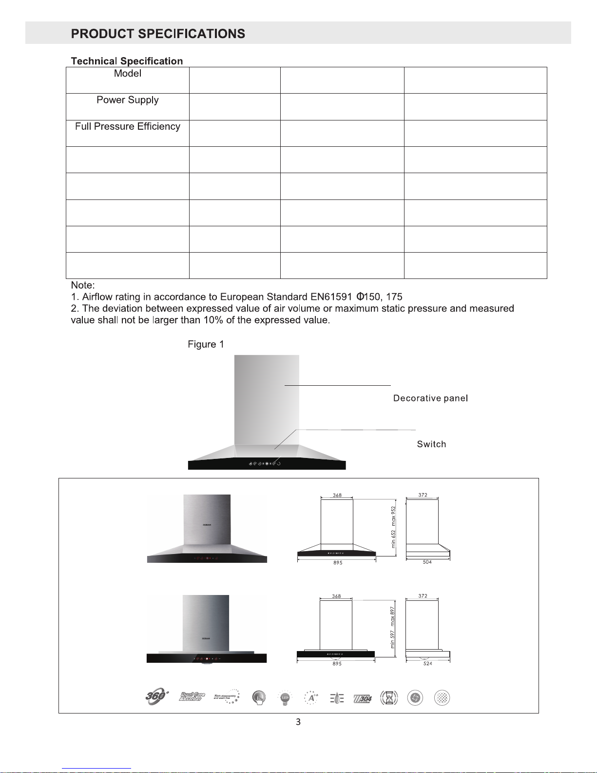
(Unit: mm)
Figure 2
Tornado A818
Crossover A809
CXW-200-A818
CXW-200-A809
Maximum Noise Level
≤57.5dB(A)
220-240V ~ 50Hz
Rated Total Input Power
204W
≥23%
Rated Motor Input Power
200W
Nominal Pressure
≥280Pa
Maximum Lighting Power
≤4W
European Standard
Maximum Airflow Rating
1140m³/hr
Dimensions (L x W x H)
A818: 895 x 504 x 652 (mm)
A809: 895 x 524 x 597 (mm)
Maximum Static
Pressure
≥350Pa
Net Weight
A818: 26kg
A809: 25.5kg
Odour Decrease Rate
(Normal)
98%
Grease Separation Rate
≥96%
Odour Decrease Rate
(Instantaneous)
80%
Minimum Distances
Cooktop: 650mm
Barbeque: 800mm
≥
≥
Page 5

4
Name
Quantity
Name
Quantity
Rangehood 1 piece ST4x18 Self Tapping
Screws
10 pieces
Non-Return Valve
1 set
ST4.8x50 Timber Screws
4 pieces
Valve Seal
Solid Wall Plug
4 pieces
Valve connector
M6 Solid Wall Anchor
1 piece
Wall Bracket
1 piece
Stopper Foot
1 piece
Oil Cup
1 piece
Semi-Rigid Duct with Tape
1 piece
User Manual
1 piece
Reducing Collar
1 piece
Page 6

a
f
pt
Ceiling
Dra wing pa nel
10m m
Ceiling
Removable panel
Removable baffle
10m m
Mou nting h ole
of th e drawi ng
pan el
ST4 X18 sel f-tap ping
scr ews
CXW-20 0-8302
Dec orati ve pane l
A818
A818
Page 7

35±2mm
235mm
65±2mm
Wall Bracket
600( 545) mm
(A818 and A 809 a re id entic al)
Ceili ng dr ill ing siz e cha rt
895 mm
Top view
of rangehood
Size in b rac ket s is specifi c to A80 9 rangehood
A818
600( 545) mm
crew
s
Φ17 5 alumi num exh aust pi pe
Exh aust pi pe tape
Φ17 5 exhau st pipe reducing collar
Φ
1
80
Φ170Φ
1
60
Φ15
0
Φ
140
Exh aust pi pe tape
Sl
Page 8

Light Timer
Timer Display
Speed Display
Filter Cleaning
Reminder
Stir-Fry
Setting
Speed
Control
Power /
Delay Timer
Page 9

Stir-fry Setting Speed Control
Power
Timer
Filter Cleaning Reminder
Light
●
●
●
●
●
●
●
Page 10

Page 11

1
RANGEHOOD TECHNICAL DIAGRAM
ELECTRICAL DIAGRAM
Fan
Cap
Air flue
Motor
Retainer ri ng
Cover p late
Flue Cover
Decorativ e pa nel
O
Oil Guide
Oil Filter
il cup
A818
Spotlight
Motor
Capacitance 500VAC 6μF
Ground terminal
Power plug
Strong extraction switch
Medium extraction switch
Weak extraction switch
Stir-frying switch
Lighting switch
LED
Yellow/Green
Yellow/Green E
Blue
Red
Brown
Orange
Grey
Black
White
Blue
Brown
Blue
Blue
Red
Yellow
Red
Connection box
Control circuit
Function circuit
L
D
220V~
XP
K5
K4
K3
K2
K1
Page 12

 Loading...