

Page 1
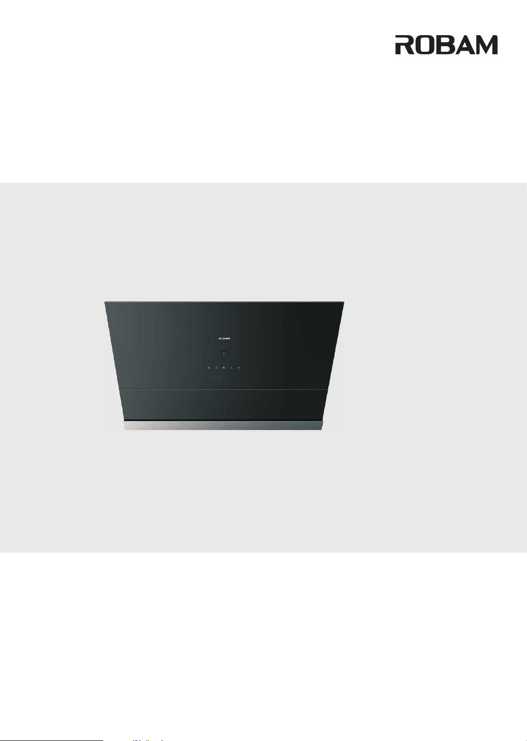
User Manual
Before operating this unit, please read the user manual completely and keep it. If the manual is lost, you can send email to [email protected] (for USA) or [email protected] (for Canada), request for an electronic manual.
CXW-260-A671
Range Hood
Page 2

CONTENTS
Safety Precaution..................................................................................................................24
Important Information............................................................................................................29
Product ...............................................................................................................29
Packing List...........................................................................................................................30
Installation.............................................................................................................................31
User Manual..........................................................................................................................41
Maintenance.........................................................................................................................42
Removal of Components.......................................................................................................43
Circuit Diagram......................................................................................................................45
Troubleshooting of General faults..........................................................................................45
Description
Page 3
Range Hood
READ AND SAVE THESE INSTRUCTIONS
Dear users:
Thank for your buying our range hood. Please accept our best regards.Please read this user manual carefully before
installation and operation.*The pictures in this manual only for your reference. If the picture isn’t accord with object, subject
to object. We keep to right to update appearance, structure or products without notice.
Safety Precaution
In order to avoid harm or property damage to the users or other person, the following distinction and marks are stipulated.
They are important safety precaution, please comply strictly based on the full understanding.
Subject to harmful or destruct degree
Danger
Warning
Notice
Notice and Prohibit Mark
Prohibit Prohibit
Warning
If ignore this sign and operate product improperly, it’s highly possible to cause danger, serious
injury or fire.
If ignore this sign and operate product improperly, it’s possible to cause danger, serious injury
or fire.
If ignore this sign and operate product improperly, it’s possible to cause injury or loss.
Prohibit
Flame
Please use this product according to manual strictly, or ROBAM shall not take any responsible
caused by improper operation.
Touch
Don't allow children or weakling to use range hood separately, or it may
Prohibit
cause electric shock or other accident.
Prohibit water on motor, switches or other electric parts; Prohibit wash
range hood by water spray. Don’t use range hood if wet or it may cause
Prohibit
electric leakage or shock.
Prohibit Touch
by Wet Hand
Prohibit
Disassembly
Danger
Strict
Execution
Neccessary
Earthed
Caution
Electric Shock
Caution Scald
Prohibit
Prohibit
Prohibit Touch
by Wet Hand
Strict
Execution
Don’t change, stretch, bind or press electric wire, or it’s possible to cause
electric shock or fire because of broken wire.
Prohibit any change of interior circuit, or it may cause injury or other
danger, for example, electric shock or fire.
Don’t touch plug, electric parts or button by wet hands, or it may cause
electric shock.
Unplug before cleaning,installing or maintaining,avoiding from electric
shock.
24
Page 4
Strict
Execution
Strict
Execution
Prohibit
Disassembly
Prohibit
Range Hood
Danger
Please turn off range hood immediately if pan got fire (range hood
shall aggravate fire if it’s working) and extinguish fire by effective action.
For example, cover flame by metal cover, turn off gas valve immediately
and remove inflammable things.
Any abnormal, please turn off power, take off plug or cut off electric
source, and contact service. It’s possible to cause electric shock or fire if
using range hood under abnormal situation.
Warning
Range hood must be installed, disassembled or maintained by professional
person.
Stove fire shall be extinguished timely when it is not used; do not
flambe under the range hood and it's prohibited to bake food under
range hood directly to prevent range hood from damaging and causing
accidents.
Prohibit
Touch
Strict
Execution
Strict
Execution
Strict
Execution
Strict
Execution
Don’t touch lamp when it’s on or just turned off in a short time, or it may
cause scald.
In order to ensure safety, range hood must be installed by specific
accessory (especially expansion pipe and wooden screws, or it may
cause accidental drop of range hood). The pipe bore and hole must fit
tightly during the installation of metal expansion pipe. It is prohibited to
make excessively large hole to prevent accidental drop of loosening
expansion pipe.
The range hood must be used by specific plug and properly ground it. It’s
possible to cause electric shock, hot plug or fire because of improper
electric wire. Installation must be executed by professional person based
on local electrical regulations. Before connect electricity, power must be
turned off.
If the supply cord is damaged, it must be replaced by the manufacturer,
its service agent or similarly qualified persons in order to avoid a hazard.
All operation must comply with our safety guidelines as well as local
safety regulations.
25
Page 5
Strict
Execution
Strict
Execution
Strict
Execution
Strict
Execution
Range Hood
Warning
There shall be adequate ventilation of the room when the range hood is
used at the same time as appliances burning gas or other fuels.
For Residential Use Only.And it’s not allowed to exhaust dangerous or
explosive matter or air. It should be put under dry and ventilation
environment without dangerous air.
The range hood and electric circuit must be installed by skilled and trained
personnel with required qualification. When installation, the related
regulation, standard or instruction on fire must be complied. It may cause
danger because of improper installation, for example, electric shock, drop or
fire accident.
The outlet must be connect with outside. In order to ensure safety and fresh
air, waste gas should be exhaust to outside. Don’t exhaust waste gas to the
wall, loft or garage.
Strict
Execution
Strict
Execution
Strict
Execution
There is a fire risk if cleaning is not carried out in accordance with the
instructions.
Keep a good habit to turn off gas hob and gas valve if go outside, sleep or
finish operation. Replace or check gas pipe regularly, since gas alarm
device can’t completely avoid accident caused by gas leakage.
TO REDUCE THE RISK OF INJURY TO PERSONS IN THE EVENT OF
A RANGE TOP GREASE FIRE, OBSERVE THE FOLLOWING:
a) SMOTHER FLAMES with a close-fitting lid, cookie sheet, or metal
tray, then turn off the burner. BE CAREFUL TO PREVENT BURNS. If the
flames do not go out immediately,EVACUATE AND CALL THE FIRE
DEPARTMENT.
b) NEVER PICK UP A FLAMING PAN – You may be burned.
c) DO NOT USE WATER, including wet dishcloths or towels – a violent
steam explosion will result.
d) Use an extinguisher ONLY if:
1) You know you have a Class ABC extinguisher, and you already know
how to operate it.
2) The fire is small and contained in the area where it started.
3) The fire department is being called.
4) You can fight the fire with your back to an exit.
26
Page 6
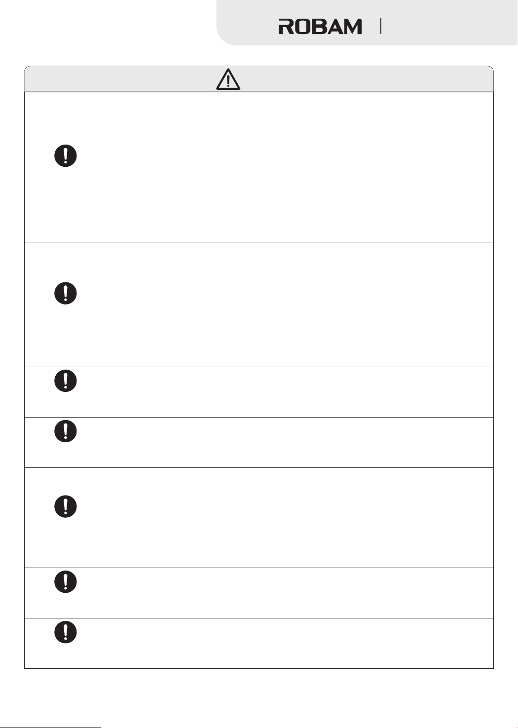
Strict
Execution
Strict
Execution
Range Hood
Warning
TO REDUCE THE RISK OF A RANGE TOP GREASE FIRE:
a) Never leave surface units unattended at high settings. Boilovers cause
smoking and greasy spillovers that may ignite. Heat oils slowly on low or
medium settings.
b) Always turn hood ON when cooking at high heat or when flambeing
food (i.e. Crepes Suzette, Cherries Jubilee, Peppercorn Beef Flambe').
c) Clean ventilating fans frequently. Grease should not be allowed to
accumulate on fan or filter.
d) Use proper pan size. Always use cookware appropriate for the size of
the surface element.
TO REDUCE THE RISK OF FIRE, ELECTRIC SHOCK, OR INJURY TO
PERSONS, OBSERVE THE FOLLOWING:
a) Installation work and electrical wiring must be done by qualified person(s)
in accordance with all applicable codes and standards, including fire-rated
construction.
b) When cutting or drilling into wall or ceiling, do not damage electrical
wiring and other hidden utilities.
c) Ducted fans must always be vented to the outdoors.
Strict
Execution
Strict
Execution
Strict
Execution
Strict
Execution
Strict
Execution
TO REDUCE THE RISK OF FIRE, USE ONLY METAL DUCTWORK.
TO PROVIDE PROTECTION AGAINST ELECTRIC SHOCK, CONNECT
TO PROPERLY GROUNDED OUTLETS ONLY.
GROUNDING INSTRUCTIONS:This appliance must be grounded. In the
event of an electrical short circuit, grounding reduces the risk of electric
shock by providing an escape wire for the electric current. This appliance
is equipped with a cord having a grounding wire with a grounding plug.
The plug must be plugged into an outlet that is properly installed and
grounded.
Improper grounding can result in a risk of electric shock.
Consult a qualified electrician if the grounding instructions are not
completely understood, or if doubt exists as to whether the appliance is
properly grounded.
27
Page 7
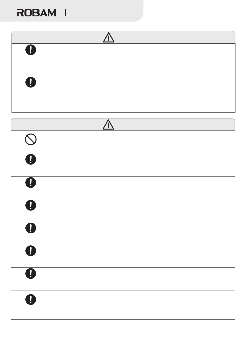
Strict
Execution
Strict
Execution
Prohibit
Range Hood
Warning
Do not use an extension cord. If the power supply cord is too short, have
a qualified electrician install an outlet near the appliance.
This appliance is not intended for use by persons (including children) with
reduced physical, sensory or mental capabilities, or lack of experience and
knowledge, unless they have been given supervision or instruction
concerning use of the appliance by a person responsible for their
safety.Children should be supervised to ensure that they do not play with the
appliance.
Notice
The air must not be discharged into a flue that is used for exhausting fumes
from appliances burning gas or other fuels, the discharge of air must fulfill
the requirements of local regulations.
Strict
Execution
Strict
Execution
Strict
Execution
Strict
Execution
Strict
Execution
Strict
Execution
Strict
Execution
Before removing range hood for installation, clean or maintainance, power
must be cut off avoiding from electric shock. When installation, clean or
maintainance, protective gloove must be wear avoiding from injury.
The temperature for range hood working can’t exceed 40℃.
Because the installation is difficult and hood is heavy, the installation
shall be executed by professional person based on manul.
Don't break electric wire or other invisible equipment when cutting
something or drilling holes on ceiling.
When range hood is using in well sealed building, it should have air inlet
or open door to ensure good ventilation.
When the oil exceeds 2/3 or near tick mark in the oil cup, clean it in
time. Don't eat waste oil from oil cup.
The wall of installing range hood needs enough strength. For hollow walls,
the thickness of solid layer of hollow wall must be more than 30mm, but for
concrete walls, it can be drill holes directly. The range hood must be fixed on
the wall firmly.
28
Page 8
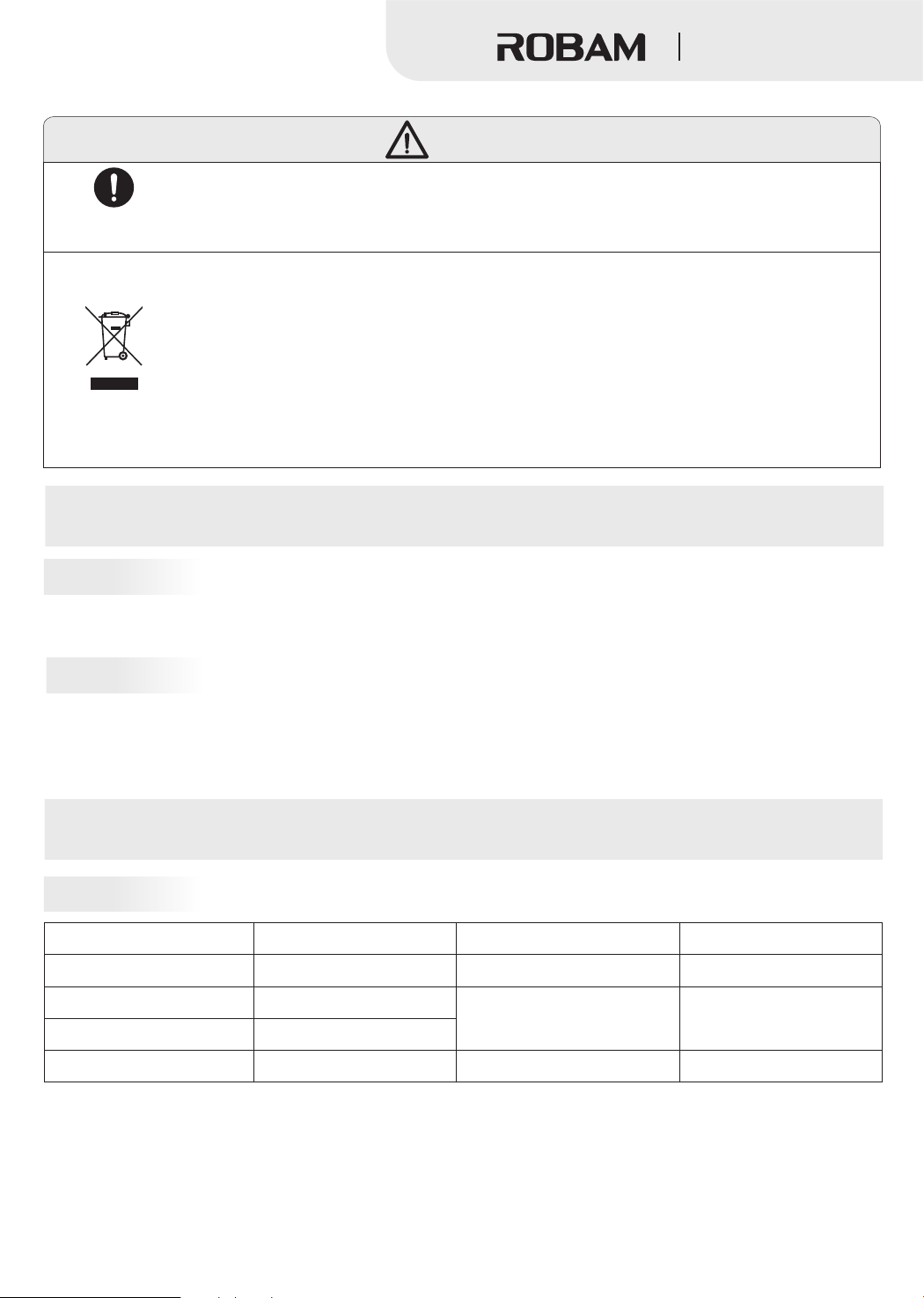
Notice
Range Hood
Strict
Accessible parts may become hot when used with cooking appliances.
Execution
DISPOSAL: Do not dispose this product as unsorted municipal waste.
Collection of such waste separately for special treatment is necessary.
This product must not be disposed together with the domestic waste. This
product has to be disposed at an authorized place for recycling of electrical
and electronic appliances.
By collecting and recycling waste, you help save natural resources, and
make sure the product is disposed in an environmental friendly and healthy
way.
Important Information
Package of Range Hood
Please settle those packages carefully in order to protect environment.
Don’t allow children to play plastic film and package, it may cause asphyxia. Please avoid children near package material.
Before use Range hood
Please read this manual and all information carefully before installation and operation. Please comply with our
suggestion. If it’s necessary, please read manual for gas hob. And please keep these manual carefully for future
reference.
If range hood has obvious damage, please don’t electrify and contact operator.
重要信息
Product Description
Technical Data
Model
Power Supply
Max static pressure
Noise
Net Weight
Note: 1. The noise value shown is the A-weighted sound power level;
2. Parameters of noise and others may have deviations of less than 5%.
CXW-260-A671
120V~ 60Hz
450Pa
67dB(A)
55.1lbs kg(25 )
Rated Power Input
Rated Main Motor Power Input
Dimension (L×W×H)
29
262W
260W
7 13 3
(29- /8×17- /16×17- /4)”
(759×452×450)mm
Page 9
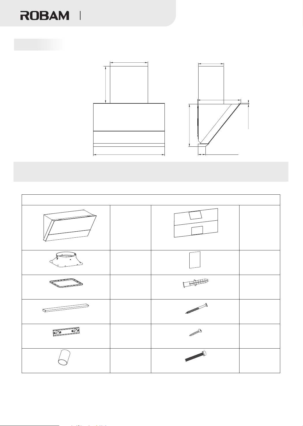
Size
Range Hood
3
15- /4”(400mm)
/8”
3
3
Min 15- (390mm)
Max 29- /8”(745 mm)
7
29- /8”(759mm)
The size marked is for reference only.
Packing List
Please check the items in the container upon unpacking
Standard Offerings
5
10- /8”(270mm)
3
18- /16”(462mm)
3
17- /4”(450mm)
3- /8”(80mm)
/8”(10mm)
3
1
1
Range hood
Hole size plate
1
Check valve
User Manual
1
Gasket
Plastic expansion pipe
1
Oil cup
4×60 wood screw
1
Hitching leg
ST4.2× 8 self tapping screw1
1
Flexible aluminum duct
M cross recess pan head screw 5×40
Note: Please mount the oil cup in the container on the machine enclosure when to use the machine.
1
1
4
4
8
4
30
Page 10
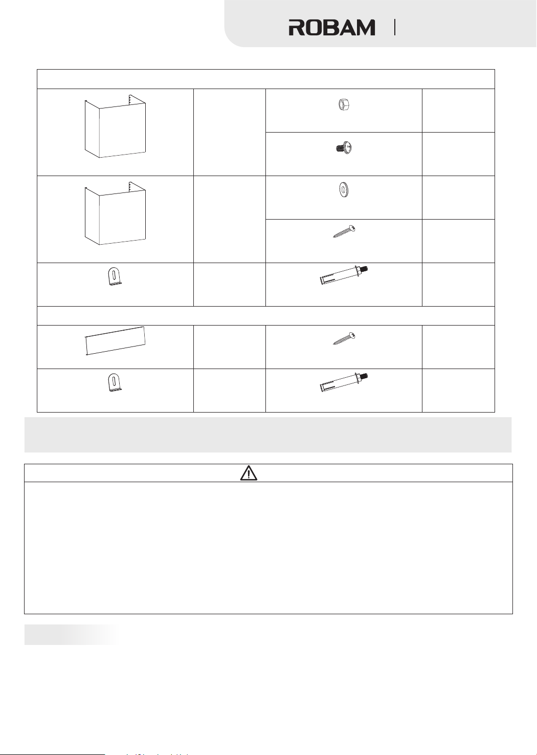
Mainframe panel
Range Hood
Mainframe panel accessories (optional)
2
M4 nut
1
2
M4×8 pan head screw assembly
Ø gasket4
1
4
2
Attached panel of the mainframe
1
Hitching leg stop block
Decoration panel accessories (optional)
1
6”or12”decoration panel
1
Hitching leg stop block
ST4.2× 8 self tapping screw1
1
M6 metal expansion pipe
4
ST4.2× 8 self tapping screw1
1
M6 metal expansion pipe
Installation
Warning
1.The air must not be discharged into a flue that is used for exhausting fumes from appliances burning gas or other fuels,
the discharge of air must fulfill the requirements of local regulations.
2.Note that when installing the metal expansion pipe, the pipe shall match with the hole in size. Overlarge hole is
prohibited, as it will result in loose pipe and accidental drops.
3.There shall be adequate ventilation of the room when the range hood is used at the same time as appliances burning gas
or other fuels.
4.If the flue aperture is less than air duct aperture, it will influence the fume suction effect and the too long air duct will
influence the fume suction effect, too.
5.This appliance just for household use only.And it’s not allowed to exhaust dangerous or explosive matter or air. It should
be put under dry and ventilation environment without dangerous air.
Preparation for installation
●Surrounding
Keep the hood away from too many doors and windows, so as to avoid air convection affecting the efficiency.
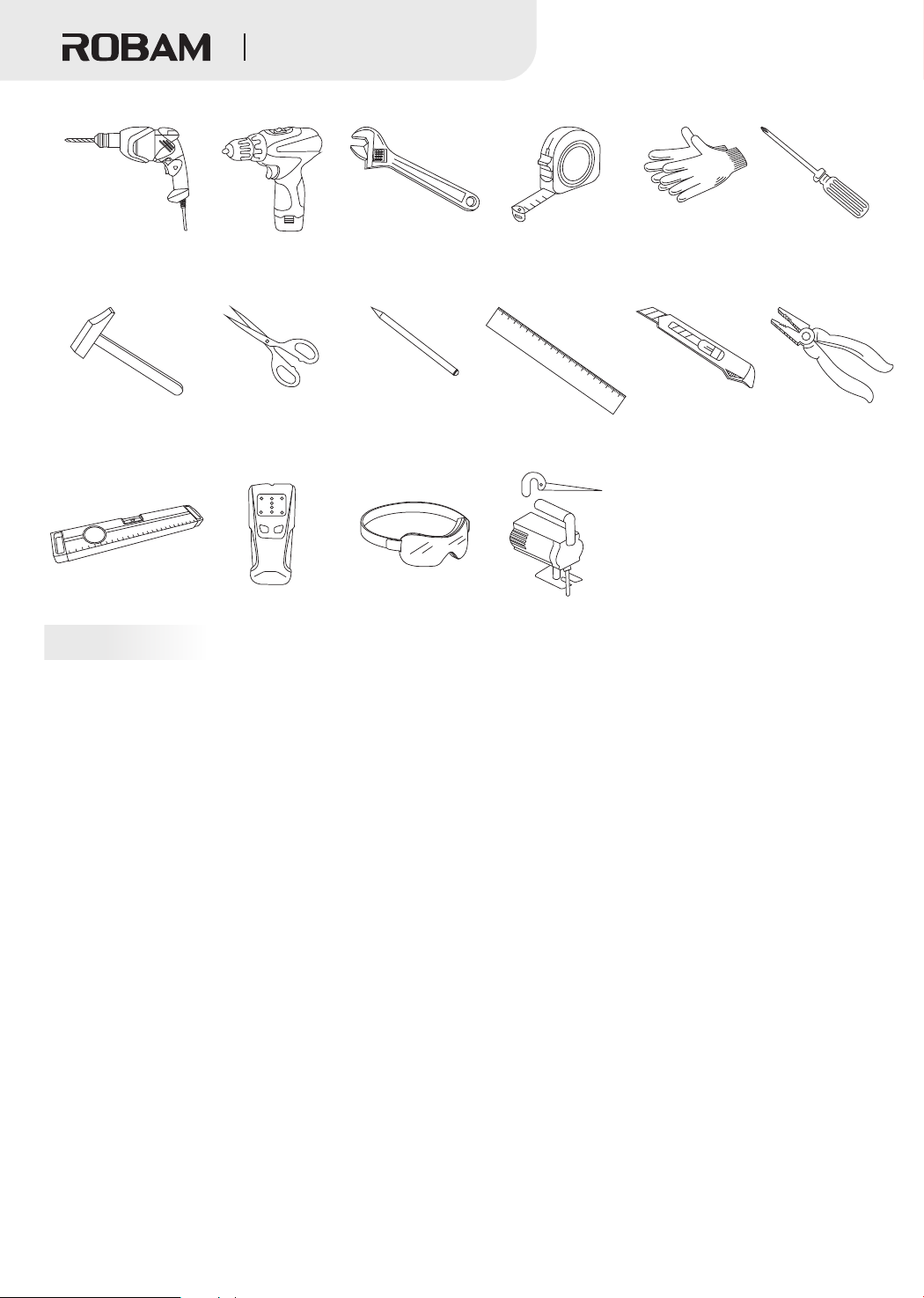
●Tools preparation
The hood will be installed with the following tools
31
Page 11
Range Hood
Electric percussion
Electric screwdriver Wrench Measuring tape
Gloves Cross screwdriver
drill
1
2
3
4
5
6
7
8
9
10
11
1
2
1
3
14
1
5
1
6
1
7
18
1
9
2
0
Hammer
Scissors
Level meter Beam detector
Pencil Ruler
Goggles
Electric saw
Art knife Cutting pliers
Notice
● Installation and circuit setting must be done by experienced professionals. Only a professionally trained person with an
installation qualification can install the hood. Non-professionals are not allowed to install, dismantle and repair the hood.
●Please do not power on the hood before installation to avoid electric shock.
●Do not expose the hood if your kitchen is under renovation, because construction materials, dusts, paint, coatings, and
emitted gases will corrode and tarnish the hood surface. Therefore, it is recommended to install it after the renovation is
completed.
●If you need move the Gas Hob before installing the Range Hood, please close the main valve before moving the Gas Hob.
●The wall shall be made of noncombustible materials with enough strength and the surface shall be flat.
●The hood may have very sharp edges. So, please wear protective gloves during hood installation, cleaning or repair.
●When drilling on the wall or ceiling board, keep away from embedded wires and other concealed devices to avoid electric
shock and fire.
●Do not install the hood at a too high position as well as keep the hood free from disturbance of ambient airflow lest the
reduction of smoke pumping effect shall occur.
●When making cabinet, please leave space for installation and disassembly of the hood in order to maintain and overhaul
the hood.
●When installing, please keep the machine body remain horizontal.
●Please use single phase grounded socket and the hood shall be well grounded (water pipe grounding is not reliable and
gas pipeline grounding has risks of causing fire disaster and explosion).
● In order to ensure safety and successful installation, please use standard accessories provided with the hood for
installation, otherwise the hood may be at risk of falling down.
● If the power cord is damaged, in order to avoid danger, it must be replaced by manufacturer, professionals of its
maintenance department or similar departments. Please do not carry out restructuring, stretching, knotting and squeezing or
apply heavy objects to the power cord, etc., otherwise it may cause power cord damage easily, leading to accidents such as
electric shock and fire disaster, etc.
●After installation, please clean the surface of the hood, and then supply power for test run.
32
Page 12
Range Hood
Installation
The range hood should be installed directly above the stove. In order to ensure the safety and the best effect of oil
fume suction, it is suggested that the minimum distance between the top of the range hood and the cooker supporting
surface on the stove should be 29- /16” mm and the maximum should not be greater than 32- /2” mm If the
state or region has laws on installation height of the range hood, please comply with the laws, but the fume suction
effect of the product may be greatly affected.The installation of the range hood can be divided into three installation
modes: no upper cabinet, with upper cabinet and upper cabinet with decoration panel.Note:
1. The hitching leg must be fixed to the beam with a screw.
2. Please operate with protective gloves and goggles.
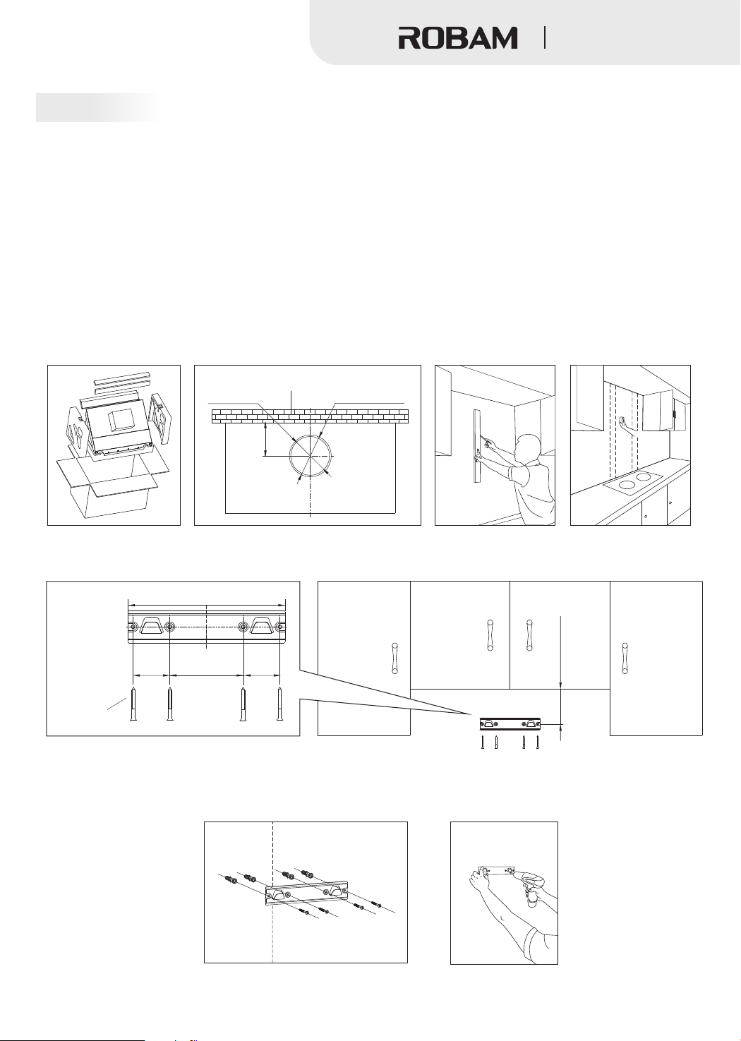
●Installation with upper cabinet
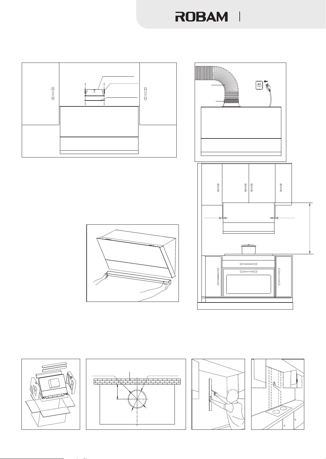
1. Open the container and take out the machine, and check the items inside against the packing list.
2. Open the duct hole at the top of the upper cabinet according to the opening position and size as shown in the picture
below.
3. Draw a vertical center line in the installation position, and then use the beam detector to find the beam to fix the
hitching leg, and mark it with a pencil.
9 1
(750 ) (825 ).
Hole diameter
Duct diameter
Ø6”(Ø153mm)
Wall
Ø6- ”(Ø165mm)
1
/2
/2
1
6- ”(Ø165mm)
4. Determine the installation position of the body hitching leg: confirm the hitching leg position with the lowest point at
the bottom of the upper cabinet plate as the base and mark the drill holes. The relevant size is given as below: the
distance from the bottom of the upper cabinet plate to the center of the hitching leg hole is 2” (50mm).
1
9- /4”(235mm)
3
2- ”
/16
(55mm)
4×60
wood screw
Drill a hole 2- ”(60mm)-2- ”(70mm) deep (not too large) at the mark with a drill bit with a diameter of ”(8mm),
5.
3 3 5
/8 /4 /16
5
/16
4- ”
(110mm)
3
2
- /16”
(55mm)
2”(50mm)
press the expansion pipe into the hole, and reliably fix the hitching leg with 4×60mm wood screws supplied with the
machine. Use a level ruler to make sure the hitching leg is in a horizontal position.
Note: The hitching leg must be fixed to the beam with a screw.
16
14
2
1
0
1
33
Page 13
Range Hood
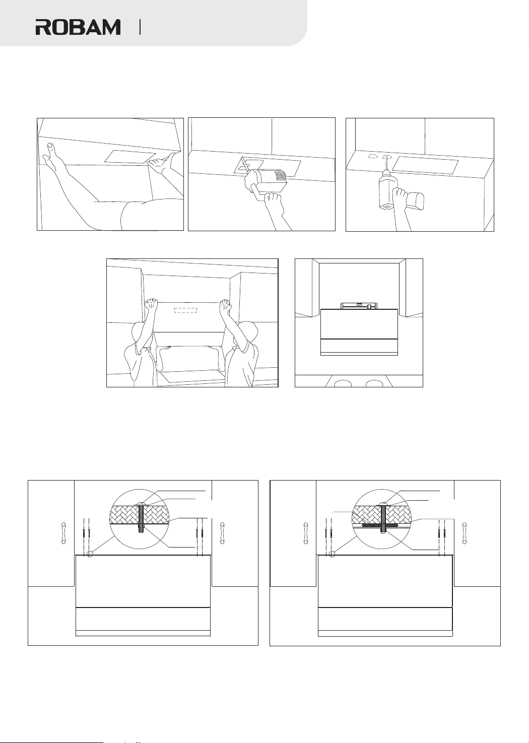
6. Paste the opening sample plate with the text surface downwards on the bottom plate of the upper cabinet, and use
the electric saw and the drill bit of diameter (7mm) to open holes according to the requirements on the opening
sample plate.
Note: wear the goggles and gloves when opening the holes.
7. Lift the range hood, hang the back hook at the hitching leg and use a level ruler to ensure that the machine is
horizontal.
1
/4”
8. Fix the range hood with four M5×40 screws from the bottom plate of the upper cabinet and fix with at least two screws
before freeing it from the hand.
9. If there is a large gap between the cabinet bottom plate and the range hood, please add cushion block according to
gap size near four M5×40 screws before installation, so as not to make the range hood enclosure deform and affect use
when fastening the screws.
Note: two or more persons are required to install this range hood for safety.
M5×40 screw
Gasket
Upper cabinet
bottom plate
Range
hood
Block
M5×40 screw
Gasket
Upper cabinet
bottom plate
Range
hood
34
Page 14
Range Hood
10. Put the sealing gasket at the air outlet of the range hood, and fix the check valve with eight ST4.2×18 screws. Attach
the duct to the check valve and seal with aluminum tape, make sure that the duct connection is sealed, and then plug it in.
Check valve
ST4.2×18 screw
Check
valve seal
Note: Please straighten the flexible aluminum duct when mounting,
to avoid noise generated when the flexible aluminum duct is semistretched, and cut off the excess parts with wire pliers. The
connection between the air outlet pipe and the wall hole or the
public flue must be tightly sealed to ensure that the air outlet pipe
is firmly connected with the check valve or the public flue, and
ensure that the blade at the connection of the check valve or the
public flue is opened and closed flexibly.
Duct
Aluminum
tape
3
/8”
(10mm)
3
/8”
(10mm)
11. After installation, the
1
9
range hood must be kept
horizontal. In the end,
insert the oil cup and
Min 29- /16”(750mm)
Max 32- /2”(825 mm)
power it for test run.
●Installation with upper cabinet and decoration panel
Note: first confirm the distance between the upper cabinet and the cooker supporting surface. Select 6” or 12” decoration
panel if the distance exceeds 32- ”(825mm).
1. Open the container and take out the machine, and check the items inside against the packing list.
2. Open the duct hole at the top of the upper cabinet according to the opening position and size as shown in the picture
below;
3. Draw a vertical center line in the installation position, and then use the beam detector to find the beam to fix the hitching
leg, and mark it with a pencil.
1
/2
Duct diameter
Ø6”(Ø153mm)
Hole diameter
Wall
1
Ø6- /2”(Ø165mm)
1
6- /2”(Ø165mm)
35
Page 15
Range Hood
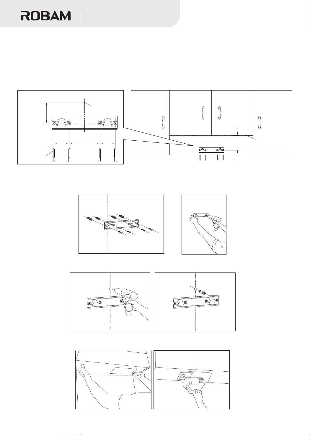
1.Determine the installation position of the hitching leg and the hitching leg fixed block: confirm the hitching leg position with
4.
the inside of the upper cabinet plate bottom as the base and mark the drill holes. The relevant size is given as below:
1)The distance from inside the bottom of the upper cabinet plate to the center of the hitching leg hole is 7- ”(181mm) when
6” decoration panel is used.
2)The distance from inside the bottom of the upper cabinet plate to the center of the hitching leg hole is 13- ” (333mm)
when 12” decoration panel is used.
3)The installment pitch of holes between the center of the hitching leg hole and the hitching leg stop block is 2- ”(60±2mm).
Hitching leg
stop block
3
mounting hole
2- /8”
(60±2mm)
3
2- /16”
(55mm)
5
4- /16”
(110mm)
3
2- /16”
(55mm)
1
7- /8”(181mm)or
1
13- /8”(333mm)
4×60
wood screw
Drill a hole 2- ”(60mm)-2- ”(70mm) deep (not too large) at the mark with a drill bit with a diameter of ”(8mm),
5.
3 3 5
/8 /4 /16
press the expansion pipe into the hole, and reliably fix the hitching leg with 4×60mm wood screws supplied with the
machine. Use a level ruler to make sure the hitching leg is in a horizontal position.
Note: The hitching leg must be fixed to the beam with a screw.
1
/8
1
/8
3
/8
Plane fixing
the decoration
panel inside
the bottom
of the upper
cabinet plate
as the base
16
4
1
12
0
1
3 3
6. Drill a hole with a diameter of ”(10mm) (not too large) and a depth of 2”(50mm)-2- ”(55mm) at the fixing hole
/8 /16
mark of the hitching leg stop block, and insert the M6 metal expansion pipe into the hole.
6
1
4
1
12
0
1
7. Paste the opening sample plate with the text surface downwards on the bottom plate of the upper cabinet, and use the
electric saw to open holes according to the requirements on the opening sample plate.
Note: wear the goggles and gloves when opening the holes.
36
Page 16
Range Hood
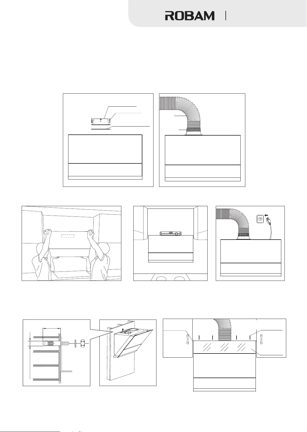
8.Put the sealing gasket at the air outlet of the range hood, and fix the check valve with eight ST4.2×18 screws. Attach
the duct to the check valve and seal with aluminum tape, make sure that the duct connection is sealed.
Note: Please straighten the flexible aluminum duct when mounting, to avoid noise generated when the flexible
aluminum duct is semi-stretched, and cut off the excess parts with wire pliers. The connection between the air
outlet pipe and the wall hole or the public flue must be tightly sealed to ensure that the air outlet pipe is firmly
connected with the check valve or the public flue, and ensure that the blade at the connection of the check
valve or the public flue is opened and closed flexibly.
Check valve
ST4.2×18 screw
Check valve seal
Duct
Aluminum
tape
9.Lift the range hood, hang the back hook at the hitching leg and use a level ruler to ensure that the machine is horizontal.
Then plug in the power.
10. After the machine is installed in place, install the hitching leg stop block and the gasket on the M6 metal expansion
pipe, and tighten the nut with a wrench (to prevent the machine from decoupling accidentally under external force).
11. Fix the decoration panel at the bottom of the upper cabinet plate with four ST4.2×18 self tapping screws and make
sure that the decoration panel is flat.
(50mm) /16
2” -2- ”(55mm)
3
Cabinet
bottom plate
ST4.2×18
Self tapping screw
6” or 12”
decoration
panel
/8
3
Ø ”(10mm)
37
Page 17
Range Hood
12. After installation, the range hood must be kept horizontal. In the end, insert the oil cup and power it for test run.
”
6 (152.4mm)
12”(304.8 mm)
3
/8”
(10mm)
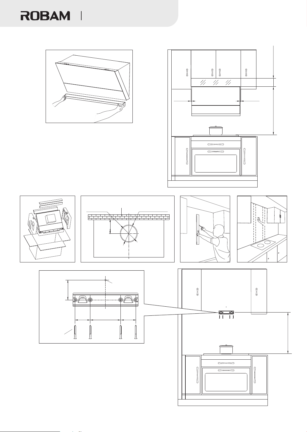
●Installation without upper cabinet
Note: select the mainframe panel accessories if there is no
cabinet above the stove.
1. Open the container and take out the machine, and check
the items inside against the packing list.
2. Open the duct hole at the top of the upper cabinet according
to the opening position and size as shown in the picture below.
3. Draw a vertical center line in the installation position, and
then use the beam detector to find the beam to fix the hitching leg, and mark it with a pencil.
Hole diameter
Duct diameter
Ø6”(Ø153mm)
Wall
1
6- /2”(Ø165mm)
1
Ø6- /2”(Ø165mm)
3
/8”
(10mm)
/16” 5
1
9
Min 29- (7 0mm)
Max 32- /2”(825 mm)
4. Determine the positions to fix the hitching leg and the hitching leg stop block.
Hitching leg
stop block
/8”
3
mounting hole
2-
(60±2mm)
3
2- ”
/16 2
(55mm)
5
/16
4- ”
(110mm)
3
- /16”
(55mm)
4×60
wood screw
Confirm the hitching leg position with the cooker supporting surface as
the base and mark the drill holes. The relevant size is given as below:
1) The minimum distance between the cooker supporting surface and
3
the center of the hitching leg hole is 28- /8 mm
”(720 )
2) The maximum distance between the cooker supporting surface and
the center of the hitching leg hole is 31- /16”(795mm);
5
3) The installment pitch of holes between the center of the hitching leg
hole and the hitching leg stop block is 2- /8”(60±2mm).
3
38
/8”
/16
3
5
(720mm)
Min 28-
(795 mm)
Max 31- ”
Page 18
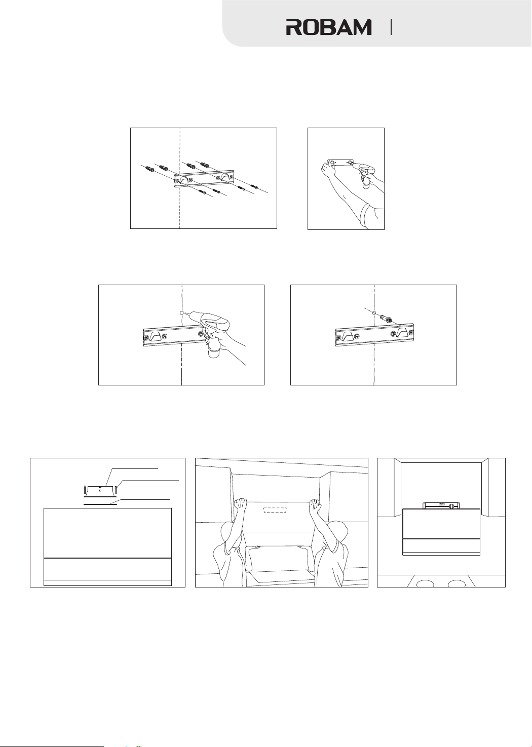
Range Hood
3 3 5
Drill a hole 2- ”(60mm)-2- ”(70mm) deep (not too large) at the mark with a drill bit with a diameter of ”(8mm),
5.
press the expansion pipe into the hole, and reliably fix the hitching leg with 4×60mm wood screws supplied with the
machine. Use a level ruler to make sure the hitching leg is in a horizontal position.
Note: The hitching leg must be fixed to the beam with a screw.
/8 /4 /16
16
4
1
2
1
0
1
6. Drill a hole with a diameter of ”(10mm) (not too large) and a depth of 2”(50mm)-2- ”(55mm) at the fixing hole
3 3
/8 /16
mark of the hitching leg stop block, and insert the M6 metal expansion pipe into the hole.
6
1
4
1
12
10
7. Put the sealing gasket at the air outlet of the range hood, and fix the check valve with eight ST4.2x18 screws.
8. Lift the range hood, hang the back hook at the hitching leg and use a level ruler to ensure that the machine is horizontal.
Check valve
ST4.2×18 screw
Check valve seal
39
Page 19
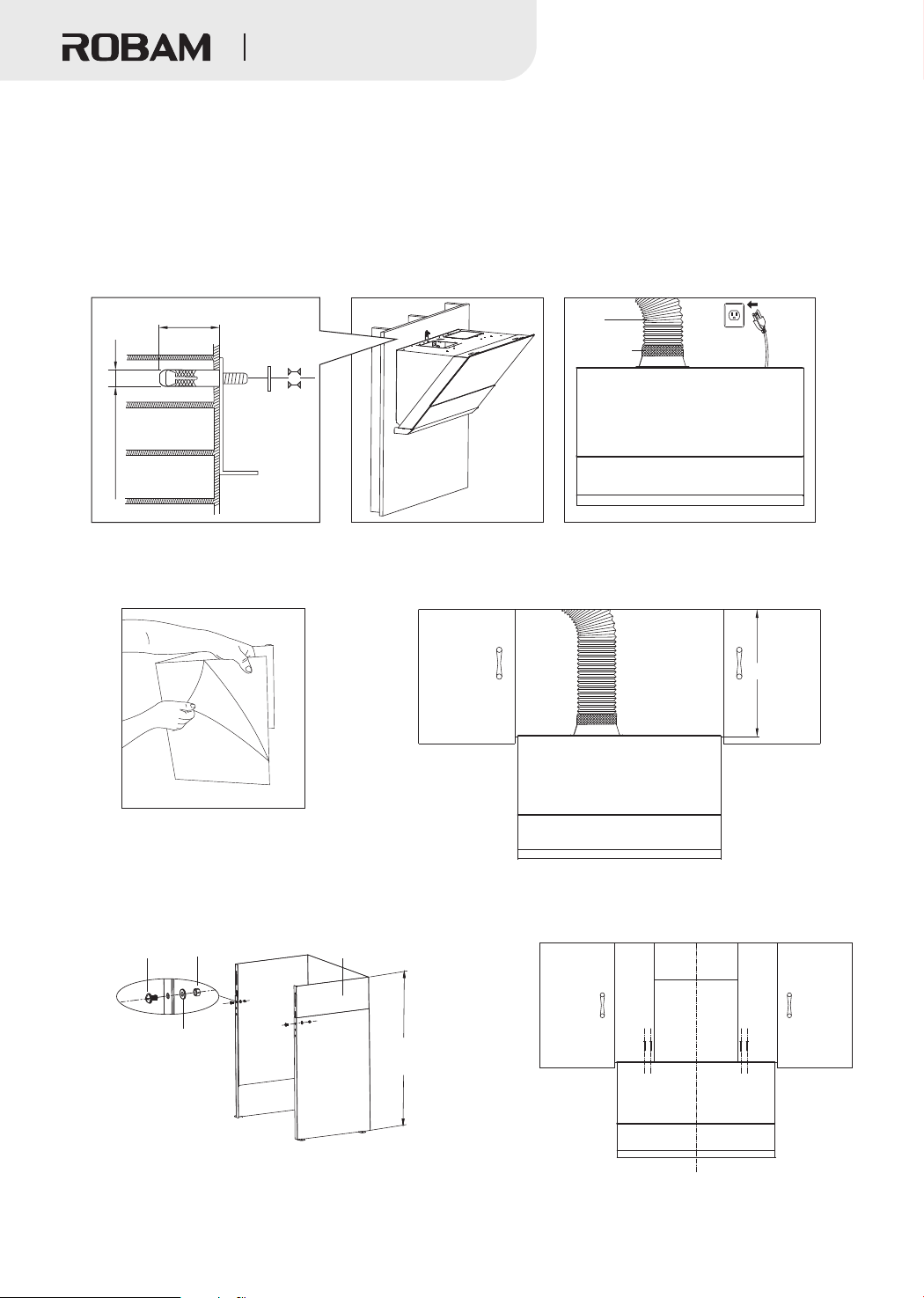
Range Hood
9.
5.After the machine is installed in place, install the hitching leg stop block and the gasket on the M6 metal expansion
pipe, and tighten the nut (to prevent the machine from decoupling accidentally under external force). Attach the duct to
the check valve and seal with aluminum tape, make sure that the duct connection is sealed, and then plug it in.
Note: Please straighten the flexible aluminum duct when mounting, to avoid noise generated when the flexible
aluminum duct is semi-stretched, and cut off the excess parts with wire pliers. The connection between the air outlet
pipe and the wall hole or the public flue must be tightly sealed to ensure that the air outlet pipe is firmly connected with
the check valve or the public flue, and ensure that the blade at the connection of the check valve or the public flue is
opened and closed flexibly.
2”(50mm)-2- /16”(55mm)
3
Ø /8”(10mm)
10.
Tear off the protective film of the panel and the attached panel of the mainframe and measure the distance X from the
machine top to the ceiling with a tape.
Note: the minimum distance X is 15- ”(400mm) and the maximum distance X is 29- ”(755mm)
3
Duct
Aluminum
tape
3 3
/4 /4
X
11. Fix the panel and the attached panel of the mainframe with two M4×8 screws, Ø4 gaskets and M4 nuts, make the
height of the whole mainframe panel consistent with the distance from the top of the machine to the ceiling, then place
the mainframe panel on the top of the machine and fix it with 4 ST4.2×18 self-tapping screws.
M4×8 screw
M4 nut
Ø4 gasket
Mainframe panel
Distance X from the
machine top to ceiling
40
Page 20
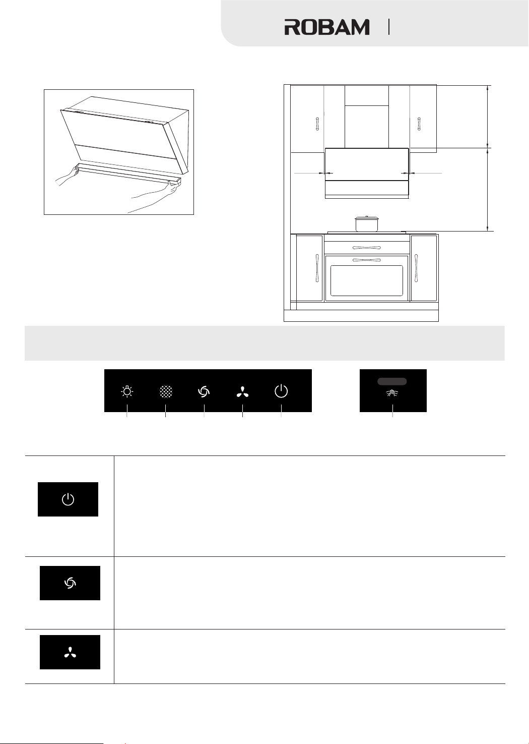
Range Hood
12. After installation, the range hood must be kept horizontal. In the end, insert the oil cup and power it for test run.
/4
/4”
3
3
mm
(400 )
Min 15-
Max 29- ”
(755 mm)
3
/8”
(10mm)
User Manual
Clean
Turbo/High
Low
Turn on the power and the buzzer will sound, indicating the power state.
Power
3
/8”
(10mm)
/2
/16”
1
9
mm
(750 )
(825 mm)
Max 32- ”
Min 29-
Wave inductionLighting
Power
Turbo/High
Low
Press the power button to enter the standby state, and the icon of the power button will be
always on.
①
If only the light is on, press the power button again to turn off the light directly;
②
When the fan is running, press the power button to make the power button icon flash and
the range hood enter the delay status. All functions will be automatically turned off after 1
minute;
③
If the power button icon is flashing, press the power button to turn off all functions.
If there is no operation within 3 minutes in standby state, enter the off state.
When the power button is on:
①Press the first time to enter the turbo gear, and the turbo/high gear icon flashes. 3 minutes
later, switch to the high gear and the icon is always on;
②Press the second time to enter the high gear, and the turbo/high gear icon light is on;
③Press the third time to turn off the high gear function, and the turbo/high gear light is off.
When the power button is on, press the low gear button. The low gear icon is always on and
the impeller rotates at a low speed for smoke extraction. Press this button again to turn off the
low gear.
41
Page 21
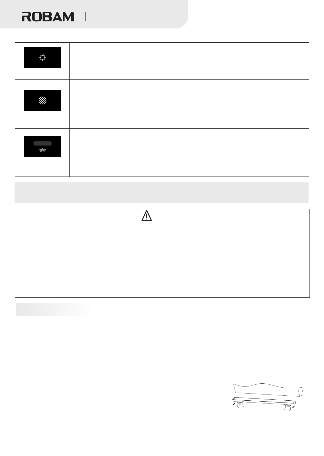
Lighting
Clean
Wave induction
Range Hood
Press the “Lighting” button, the light is on, then press the “Lighting” button again to turn
off the light. Press the lighting button when the power button is off, the light and the
air deflector are turned on at the same time.
After the hood runs for 60 hours cumulatively, the cleaning icon flashes to remind the user to clean
the oil screen. At this time, long press the cleaning button, and the cleaning icon is always on to
enter the cleaning mode (the fan stops and the air valve opens. The other buttons are invalid
except the cleaning and lighting buttons). The user can clean the oil screen. After cleaning, long
press this button, and the cleaning icon is off to exit the cleaning mode and clear the cumulative
time. Or long press the cleaning button in normal state to enter the cleaning mode.
This machine has infrared wave induction function. If the hand moves within a certain distance
in front of the infrared probe, the range hood will respond automatically. In off mode:
Wave for the first time to automatically turn on the power button;
Wave for the second time to automatically turn on the turbo function;
Wave for the third time to automatically turn off the turbo function and the fan stops working.
Maintenance
Warning
1.There is a fire risk if cleaning is not carried out in accordance with the instructions.
2.Cleaning and maintenance shall be conducted under outage. Electrical components such as motor, switch, and
connector shall not be spoiled by water so as to prevent from accidents.
3.It's prohibited to wash with water so as to prevent accidents.
4.Stove fire shall be extinguished timely when it is not used; do not flambe under the range hood and it's
prohibited to bake food under range hood directly to prevent range hood from damaging and causing accidents.
5.If the supply cord is damaged, it must be replaced by the manufacturer, its service agent or similarly qualified
persons in order to avoid a hazard.
6.Accessible parts may become hot when used with cooking appliances.
Precautions
●The range hood should be maintained and cleaned on a regular basis to keep the body clean and ensure the use
effect according to the use environment conditions, to extend the service life. You are recommended to wipe the outer
surface of the product after each cooking.
●Do not use strong detergent. It is recommended to clean with neutral detergent and dry with soft cloth. If your range
hood has a mechanical switch, prevent the detergent from touching the control keys.
●Do not keep the stains too long on the surface of the hood.
●Do not use cleaning ball, brush and other coarse materials to clean the hood to prevent scratching the body surface.
●Wear protective gloves when cleaning or maintaining the hood to prevent injury during wiping.
●Check and clean the oil cup regularly. When more than 2/3 oil has accumulated
in the oil cup, hold the oil cup with both hands, pan it out and pour out the waste oil.
●The range hood shall be turned on before cooking.
●Pull out the power plug that is not in use for a long time, but do not pull hard.
42
Page 22
Range Hood
Removal of Components
Warning
1. As a general rule, the hood body does not need to remove, and removal shall be done by professional maintainers.
Nonprofessionals are forbidden to remove, install and repair the hood.
2. Before cleaning, installation or maintenance for the range hood, cut off the power supply to avoid electric shock.
Note: The installation procedures of the following components are in reverse with the removal. Please wear protective
gloves during operation to prevent the sharp edge of metal hurting your hands.
Lamp removal
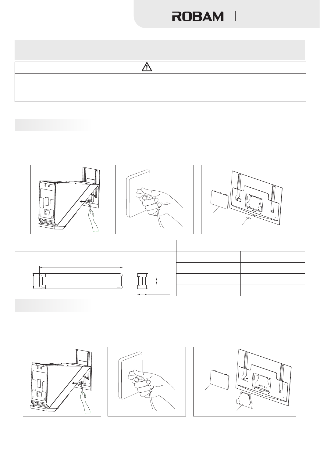
1. Long press the cleaning button to open the air deflector, unplug the power, use a cross screwdriver to unscrew the two
screws on the cover plate and take out the cover plate according to the direction of the arrow;
2.Push out the lamp from the inside by hand and unplug the connecting wire for repair and replacement.
Cover plate
Lamp
Lamp image
1
2- /8”(54mm)
/16”(5mm)
/8”
3
(10mm)
3
1
/4”(7mm)
Lamp Type
Max Power
Voltage
Lamp information
Size
Rectangular LED
2W
12VDC
See the lamp image
Switch removal
1. Long press the cleaning button to open the air deflector, unplug the power, use a cross screwdriver to unscrew the
two screws on the cover plate and take out the cover plate according to the direction of the arrow;
2. Pull out the switch assembly and unplug the connecting wire for repair and replacement.
43
Cover plate
Switch assembly
Page 23
Range Hood
Filer disassembly
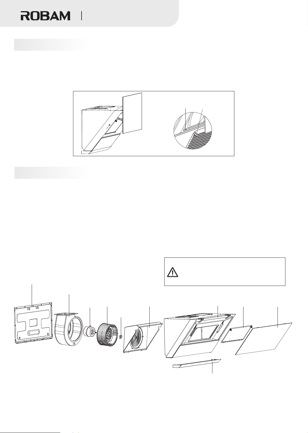
1. Long press the cleaning button to open the air deflector.
2. Hold the two magnetic clasps on the filter with both hands, slightly exert force outwards to make the filter no longer
be absorbed, then lift the filter according to the direction of the arrow to make it separated from the neck, and finally
pull out the filter to clean the filter.
Neck
Magnetic clasp
Hood disassembly
Take down the lamp according to the lamp disassembly steps;
1.
2.Take down the switch assembly according to the switch disassembly steps;
3.Take down the filter according to the filter disassembly steps;
4.Unscrews the screw on the back plate, remove the back plate, unscrew the screws on the air duct outlet, remove the
air duct and unscrew the 6 screws on the check ring;
5.Unscrew the cap clockwise and take out the impeller vertically;
The assembly steps are opposite to the disassembly steps.
(When installing the impeller, please apply some lubricating oil in the axle hole of the impeller.)
The body may not be disassembled under
normal circumstances.
Back plate
The disassembly work should be completed
by professional maintenance personnel.
Duct
Motor
Impeller
Cap
Check ring
44
Mainframe
Oil cup
Filter
Air deflector
Page 24
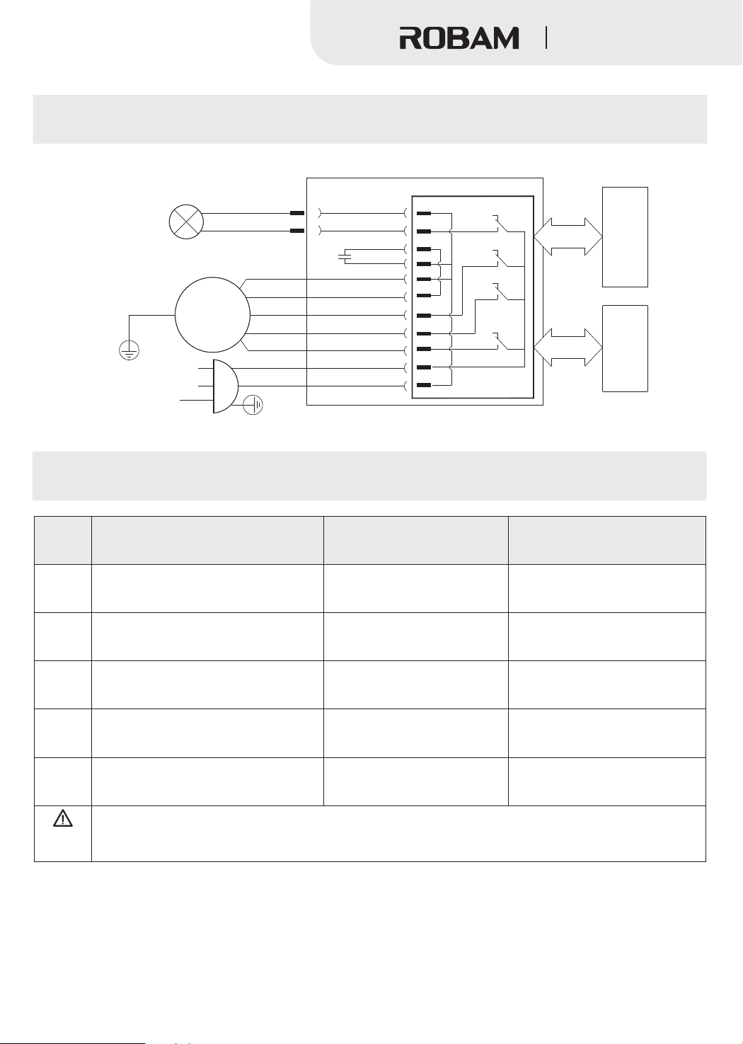
LED
Yellow/Green
120V~ 60Hz
M
L
N
black/blue
red
XP
Circuit diagram
Electrical Connection Diagram:
black/blue
C
brown
orange
gray
black
blue
black
white
Yellow/Green
red
black
white
Control circuit
K4
K3
K2
K1
Range Hood
Operating Circuit
Electric Putter
Serial
number
1
2
3
4
5
Warning
Troubleshooting of General faults
Fault
No response after pressing any icon
(e.g. the impeller does not rotate,
or the light is off)
Pressing the lighting icon, the
headlamp is not lit
Induced current exists on the hood
body may paralyze hands
Abnormal sound during impeller running
No oil in the oil cup after a
period of time
1.When connecting or replacing the plug, please unplug the power plug.
2.If the range hood's power cords are damaged,it must be replaced by our company's professional
maintenance staff.
The power plug is not connected
properly or there is power failure
The impeller is loose, and the
Cause
The light is damaged or
poorly connected
The power socket is not
grounded well
cap is not tightened
The hood body is tilt
Replace the light or plug in the plug
Use single-phase three-pole
socket and well grounded
Adjust the body to the horizontal state
Solution
Plug in the power plug
Tighten the cap
45
 Loading...