

Page 1
Operation Manual
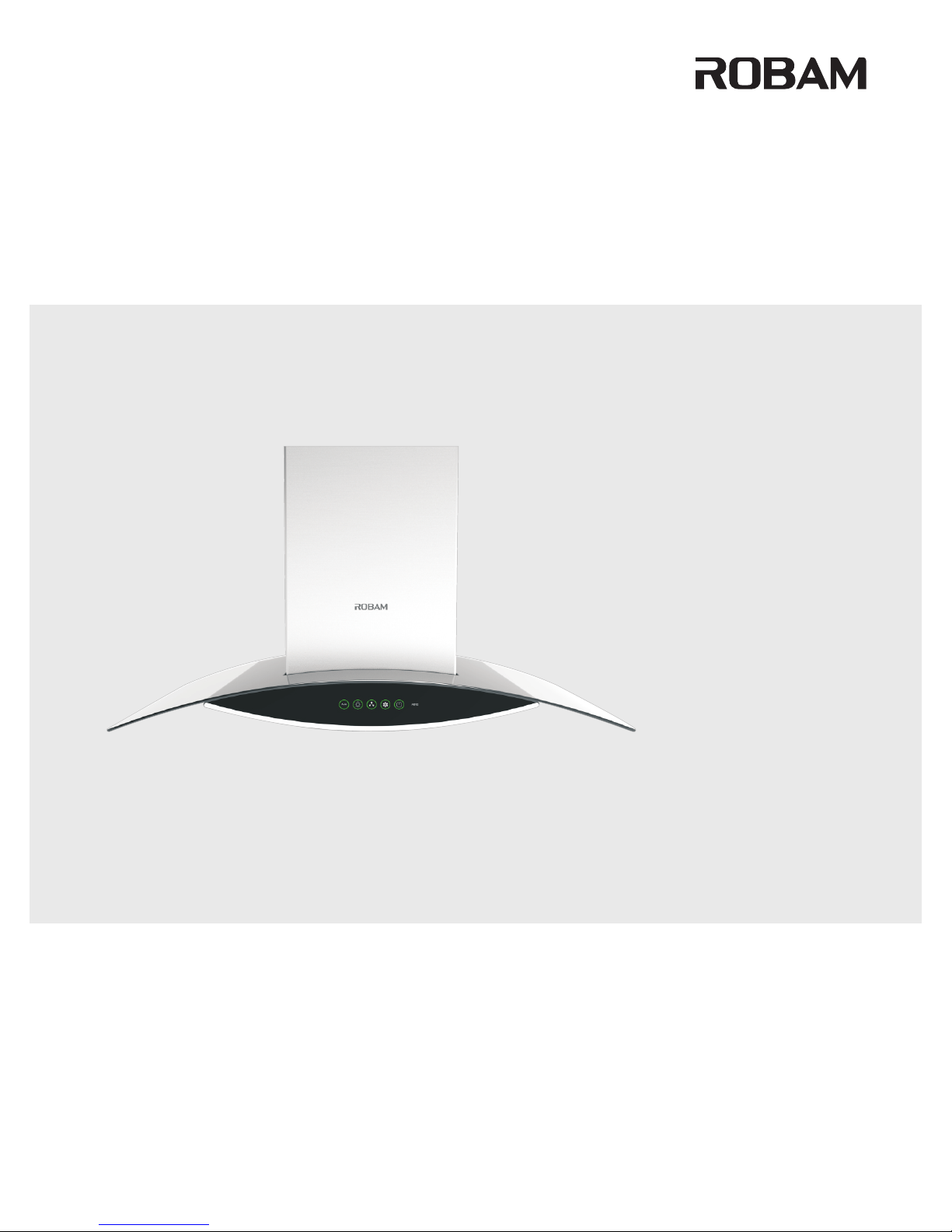
Range Hood
CXW-200-A812
CXW-200-A608
Page 2

1. Important Information 1
2. Product Overview 1
3. Packing list 2
4. Installation 3
5. Use Instruction 6
6. Maintenance and Services 7
7. Circuit Diagram 9
8. General Troubleshooting 9
.........................
................................
........................................
.........................................
...................................
..................
..................................
.....................
CONTENTS
Page 3
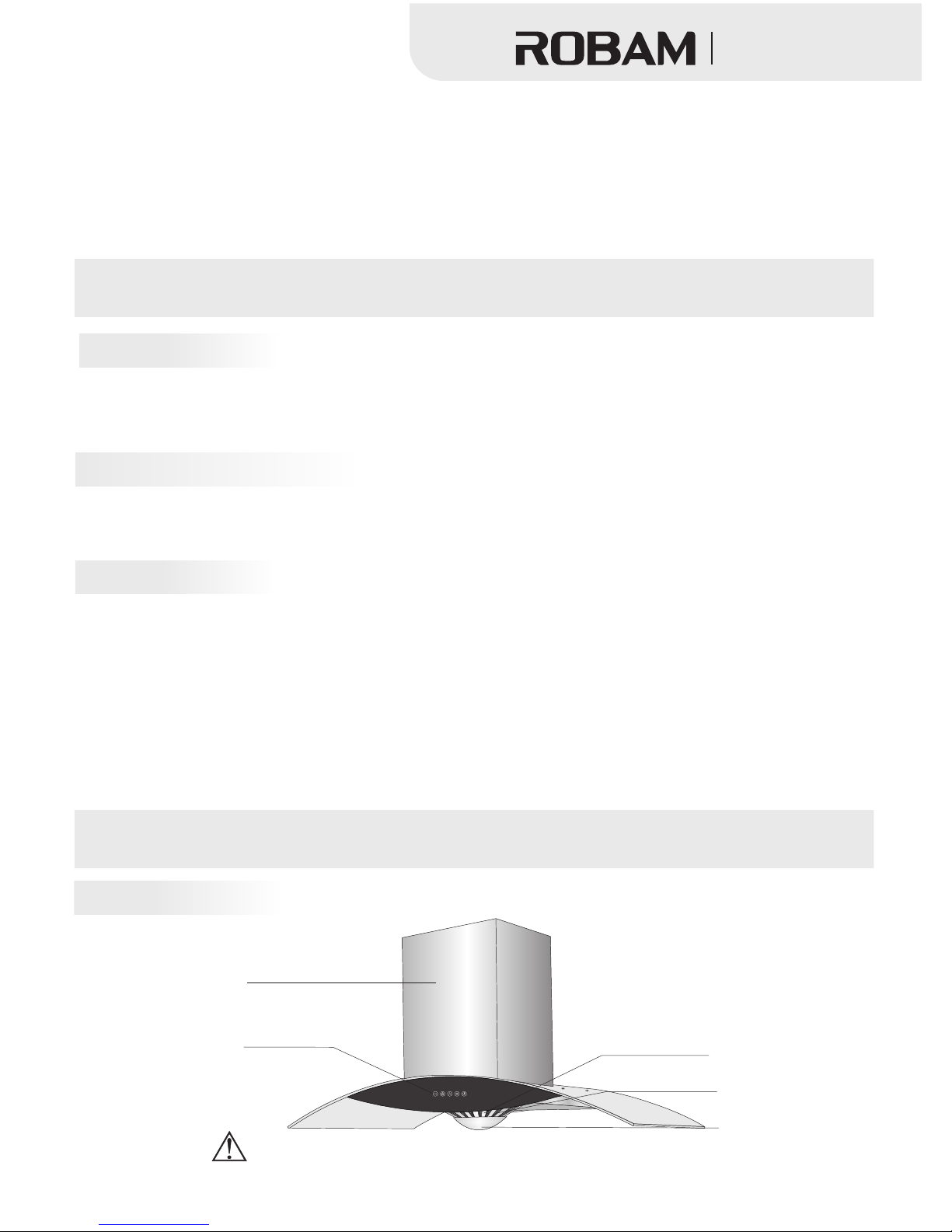
Improper oper ation may cause hazardous effect.
Panel
Switch
Oil mesh
Oil cup
Filter
吸油烟机
Range Hood
图1
Important Information
Dear users
Product Overview
New Package of Range Hood
Dispose Old Range Hood
Before use new range hood
Know your range hood:
1
A812
Thank for yo ur buying our range hood. Please accept our best regards. Please read this operation manual
carefully before installatio n and operation.
* The pictures in the manual for referen ce only. If picture s and actua l are discrepancy, please see actual object.
ROBAM keep s right to update structure or appearance without a dditional notice.
Please settle those packages carefully in order to protect environment.
Don’t allow children to play plastic film and package, it may cause asphyxia. Please avoid children near
package material.
If the old range hood can’t work, we suggest users to dispose them after confirming without any usage.
There are something useful material inside of old range hood, please assist us to dispose so as to
protect environment.
This range hood exhaust fume outside.
Please read this manual and all information carefully before installation and operation. Please comply
with our suggestion. If it’s necessary, please read manual for gas hob. And please keep these manual
carefully for future reference.
This manual is available for different models. So you may find different description with your own range
hood.
If range hood has obvious damage, please don’t electrify and contact operator.
Children and disability are not allowed to use range hood independently in order to avoid accident.
Page 4
A812
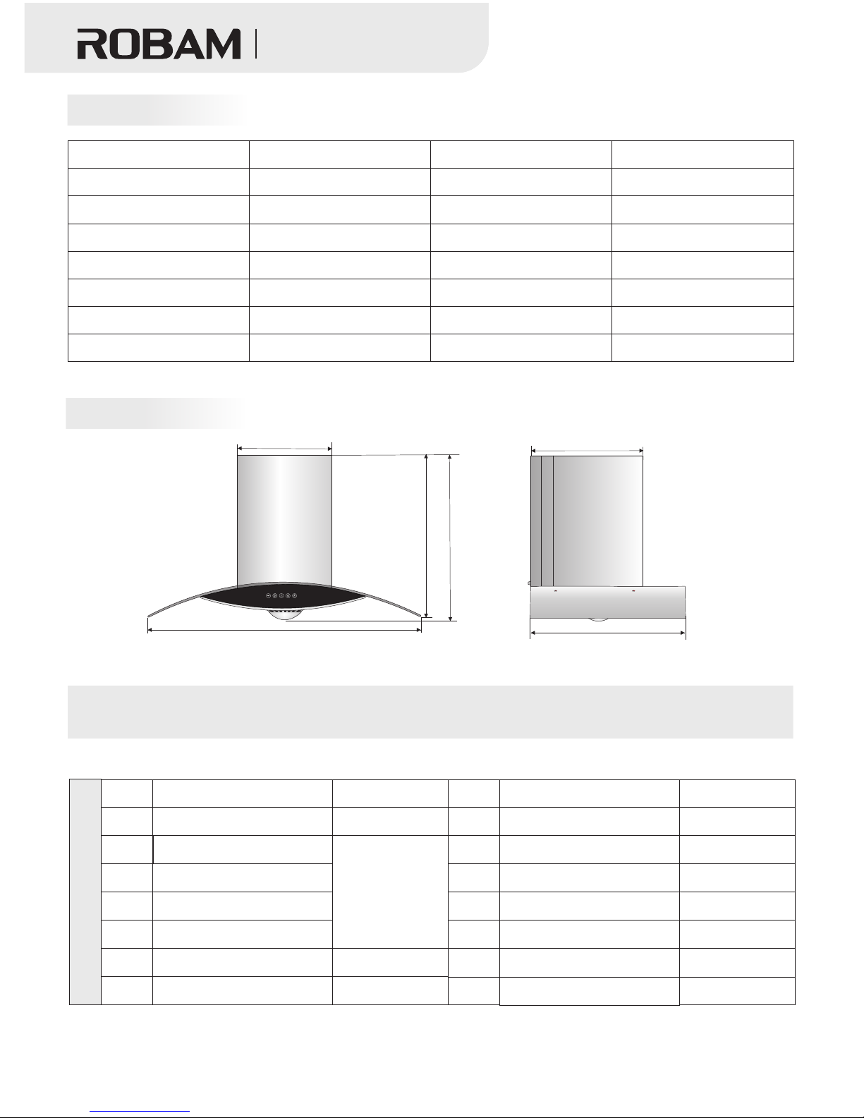
317
895(600 )
370
520
568
545(500 )
Note: The size ju st for reference. Size i n the brackets is s pecific to A608 hood. (Unit: mm)
Packing List
S/ C
Name
Quantity
S/ C
Name
Quantity
1
12
11
6
5
4
3
2
Range Hood
Plastic expansion tube
Manual
1 unit
4 unit
1 unit
Check Valve
1 pair
ST 4x18tapping screw
10 pieces
Φ175 (OD) aluminum exhaust pipe
13
14
ST 4x60wooden screw
4 pieces
10
Stop block for b racke t
1 unit
M6 metal expansion tube
1 pair
7
Oil cup
1 pieces
Bracket
1 piece
8
Φ175 (OD) exhaust pipe joint
9
Exhaust pipe tape
Fixed bar for exhaust pipe
1 pair
吸油烟机
Range Hood
Packing List
Size & Dimensio n
A812:895 x 520 x 545(mm)
A608:600 x 520 x 500(mm)
≤58dB
A812:25kg A608:24kg
≥90%
≤4W
204W
200W
Size(L x W x H)
Rated Main Motor Input Power
Max Lighting Po wer
Rated Whole Machine Input Power
Grease separa tion degree
Net Weight
Noise
≥220Pa
≥310Pa
≥23%
≥78%
≥98%
Normal Odor Reduction Degree
Instantaneous Odor Reduction Degree
Max Static Pres sure
Total Pressure Efficienc y
Nominal Wind Pr essure
Model
Power Supply
Air Flow Rate
Note: The toler ance between listed air flow r ate and actual da ta should be less than 10%.
CXW-200-A812
CXW-200-A608
Please check fo llowing items after opening the carton:
Technical Parameter
2
3
17m /min
220-240V~ 50H z
Page 5

吸油烟机
Range Hood
3
Installation
War ni ng
Preparation
Notice
1.2The range hood is prohibited from exhausting fume into hot flue , which is used for exhausting gas fuel or other
fuel fume.
.When installing metal expansion tube, ensure perfect match of tube diameter with hole diameter to prevent
accidental falling off from loosened expansion tube due to excessive hole expansion.
3.Please keep good ventilation in the room when range hood is working as while as and gas or other fuel combustion .
4.If flue outlet is smaller than air duct, or the air duct is too long, the absorbing will be affected.
5.This product is only used in the home daily. Don’t use it in the special environment (such as outside), or exhaust
dangerous or explosive air. Please put hood in the dry, good ventilation or safe environment before installation.
●
●
1. 2. 3 4
Ambient environment
Range hood shall be installed away from positions with too many windows or doors, which will lead to strong air
convection and thus reduce the effect of fume removal.
Tools:Installing range hood requires the following tools:
impact electric drill( with drill bit); Wrench; .Screwdriver; .Ruler
●
●Don' t conn ect electricity before ins tallation avo iding from electric shock.
●
●
●
●
●Don' t inst all range hood too high or disturbed by air. It may re duce absorbing effect.
●Please keep eno ugh space when installing kitchen cabinet s o as to maintain and repair.
●Please keep hoo d parallel when installation.
● Please keep earth well. ( It’s dangerous to connect ho od with water pipe or gas pip e, it may cause fire or
explosion).
●Pleae use appoi nted accessories to install hood or it may fall d own.
●If wire is broken, only manufa cture, appointed serv ice department or other professional e ngineers to
change it. Don't change,stretch ,press or bind wire, or it may cause wire destroyed, fire or electric
shock.
Installatio n and c ircuit setting must be done by experienced professionals . No n-professionals are not
allowed to inst all, dismantle and repair the hood.
Do not expose the h ood if your kitchen is under ren ovation, beca use construction materials, dusts, pain t,
coatings, an d emitted gases will corrode and t arnish the hood surfa ce. Therefore, it is recommended to
install it afte r the renovation is complete d.
Don' t install the hood on wood and othe r combustible walls. The wall shall be made of noncombustible
materials wit h enough strength.
The ho od may have very sharp edges. So, please wear protec tive g loves during hood installat ion, c leaning
or repair.
Please be care of e lectricity inside of wall when operator dig ging holes on the w all. It may causes fire.
Page 6

Picture 2
bracket
235mm
110mm
55mm 55mm
505 mm
65±2mm
35±2 mm
Stop blo ck
for brac ket
A812
A812
380
520
430
Picture 1
Ceiling
6
0
0
-8
0
0
mm
6
5
0
-
7
5
0
m
m
8
0
0
-9
0
0
m
m
Drawin g pan el
10mm
Ceiling
Removable panel
Removable baffle
6
0
0
-8
0
0
mm
6
5
0
-
7
5
0
m
m
8
0
0
-
9
0
0
m
m
10mm
(Picture 1 -1 installation without re movable baffle) ( Picture 1-2 intallati on with removable baffle )
Decora tiv e panel
Picture 3
wall
Instal lat ion size on t he ce iling (mm )
Size in th e bra ckets is sp eci fic to A608 hoo d.(Uni t: mm )
Range ho od
Projec tio n size
Duct hol e siz eφ20 0mm
吸油烟机
Range Hood
A812
Installation
●Install bracket
D
rill four 60-70mm-deep holes by Φ8mm drill bit at positions corresponding to the hanging plate dimension.
Force the expansion tube into the holes and fasten firmly the hanging plate by the supplied four 4×60
wooden screws. Drill a 50-55mm-deepΦ10mm hole at position 65mm high from the four holes and force the
M6 metal expansion tube into the hole.(picture 2)
Adjust the drawing panel
Pull the brackets of the panel up to an appropriate height and then pull the panel sides to find the drawing
panel. Remove the protective film, and insert it along the gap between th e decorative pan el and the housing.
Then adjust it to the pro per height .
●
4
● 650
2
3
650
Location:Reference dimension for installation of removable baffle is (mm),but subject to adjustment
according to actual situations. The installation hole(picture ) shall be centered vertically with the hood body and
kept horizontally.
Please see picture for the installation size on the ceiling.
Operator shall install range hood upright the gas hob with recommended lowest height between hood bottom
and cooktop is mm (if maximum installation distance is specified in the instruction of installation, this shall be
taken into consideration;
The installation height can be reduced according to actual situations when there is electric hob).
Mou nting h ole
of th e drawi ng
pan el
ST4 X18 sel f-tap ping
scr ews
895 (600)
520
447 .5
111
Page 7

吸油烟机
Range Hood
The hole diameter shall be cl ose to that of the exhaust pipe. Undersi zed hole will cause poo r
exhaust efficienc y, mor e nois es and lower airflow. The connection between the pipe and the ho le
or the public flue mu st be sealed tightly to ensur e that, the p ipe and the c heck val ve or public flue
is con nected securely . The blades at the check valve connection or pu blic flue connection must
be flexible.
Picture 4
Body
Check v alv e
Check v alv e con nection
ST4×18 sc rew
Check v alv e sea ls
Not e: During installation, s traighten the alumi num ex haust pipe to avoid
noi ses in semi-stretched sta te. Excess part may be cut with a w ire cutter.
Snap
Slot
●Install th e aluminum exh austing pi pe (The public flue pipe do n't need to drill ho les).
a.
b.
c.
●Connect aluminum exhaustin g pipe
Aluminum e xhaust pipe and hob facing the wind ow:
Remove one of the glasses a nd install a plywood with ve ntilation holes or punch directly on the glass.
Hob away from the window:
Install the aluminum e xhaust pipe throug h the window that is close to the hob and connected outside, or
install it by punching on the wall that is close to the hob and conn ected outside.
Drill hole thr ough the wall
Determine the location of the aluminum exhau st pipe against the wall and d raw the drilling range (i.e. a
circle slight ly larger than the pipe OD) . Use a long drill bi t to d rill through the wall. P ay attention to the wall
structure and mate rial, so as not to destroy other part s of th e wall.
Firstly, Insert the othe r pipe end to the pipe connection and stic k with tapes. Then, st raighten th e aluminum
exhaust pipe to conn ect the public flue pipe ( If no public flue pipe , p lease pull the al uminum exhasut pipe to
outdoors directly). This can be done directly when the wall hole is larger t han the pipe. Otherwise , there are
four pip e ends (OD: 14 0 , 150, 16 0 , an d 170 respect ively) to be chosen f rom according to the hole size .
Then cut the excess pa rt wi th sc issors.
Then, insert the pipe end with fixed bar to the exte rnal ring of check valve , and stick with tape. Fina lly, put
4 snaps in the 4 slots, and revolv e clockwise to fix exhasu t pipe on th e check valve.
Φ175 alu min um exhaus t pip e
Exhaus t pip e tape
Φ175 exh aus t pipe conn ect ion
Cut the ex ces s part smal ler t han the hol e
Φ180
Φ170
Φ160
Φ150
Φ140
Exhaus t pip e tape
Install aluminum exhaust pipe
Picture 5
5
●
●
Install th e hood body
Fix the ch eck valve as shown in Picture 5. Then direct the hanging holes in t he back o f hood at the hooks of
hitching foots accor ding to Picture 2, and press them together. Shake the body to check if it's hu ng securely.
After the body is m ounted, inst all the hitching fo ot stopper and gaskets to the M 6 metal expansion pipe, and then
tighten the nuts (to prevent accidental decoupling of the body under external force).
Install th e drawing panel
Aas shown in Picture 1-1, there is some gaps between the drawing pa nel and the top plate. Pu sh the panel against
the top plate and then fix it to the top plate with ST4×18 sc rews.
Don' t need to adjust a nd install drawing pane l in Pi cture 1 -2
Page 8

Use Instruction
吸油烟机
Range Hood
High
Low
Light
Power
Auto
6
Plug in and 3 tick fr om the buzzer will indicate qu alified insta llation. The hood is in standby.
●Press the light b utton to turn on the light and rep ress to turn it off.
● Press the power button, the light of “Powe r” buttonturn on, press
“High” b utton, the motor work with high speed. If press the “Low”
button,i t will work in the normal speed states.
●Afte r connect with p ower,pre ss “Power” button, the li ght of “Power”
turn o n, press “Low”, the motor works with low speed, press “High”
button again, it will change to high speed level.
●When the power icon is lit up and only the s potlight is “ON”, press
the “Power” button gently and the spotlight will be turned off directly; if
the fan is working, press the”Power” button, the power icon will flas h
and the fan will be shut down after 1min. (The fu nction of “Light”, “ High”,
“Low” and “Auto” bu tton can’t be working under delay status). If the
“Power” icon is spotlight, Press th e “ Power” button again, all functio ns
will be disable d.
● When " Po wer" icon turns on, press "Auto", the gas se nsor and
heat sensor will be turned on. During cooking status, if the gas
concentrati on or tempe rature reaches default , hood will turn on high
speed, and " High" icon will tur n on. Just press "Power" or " Auto "
to cancel gas sen sor or heat sensor function.
Auto
Light
Low High
Power
Switch Control Panel
Page 9

Note: when inst all light, just push light on th e oil mesh by hands.
●Raise it outward forcibly to remove the spotlight from
the hood. Pull out the connector to replace the spotlight.
●Insert a small fl athead screwdriver or some thing
sharp in the gap be tween the light cover and hood.
吸油烟机
Range Hood
●Use a Phillips sc rewdriver to remove the six
screws on the gla ss cover, then remove glass cov er.
●Then remove scr ews from switches to maintai n or
replace switc hes.
Notes
Light Removal
Switch Removal
7
Warning
Maintenance and Service
1.The re is a risk of fire if the appliance is not cleaned according t o the methods stated in the instructions.
2. Clea ning and maintenance must be done when the power is disconnected. Keep the electrical co mponents
(e.g. motors, switches a nd connecto rs) away from water to avoid acc idents. Don’t touch plug, electri c
components or switch es by wet hands.
3. Usually, hood body don’t nee d to disassemble. Only professional engineers can disassemble range hood.
Plug must be taken off before disassembly hoo d.
4.Don' t rinse with water to avoid accidents.
5. put ou t the fire promptly after use. Don't use the hob to bake the hood directly. Don't cook food directl y
under the hood. Otherwise, it will damage th e hood, causing accidents.
●
●Don' t use hi gh detergent , we recommend to u se
●Don' t leav e blot on the surface of hood too long time.
●Don' t clea n hood by cleaning ball, brush or other harsh too ls avoiding fro m scoring.
●Please wear glo ve when clean or maintain hood avoiding from hu rt.
●
●Don' t touc h opening bulb or closing for short time bulb avo iding from scald.
●
The hood shall be c leaned and maintained regularly dependi ng on the surroun dings, so as to keep its
cleanness & efficiency a nd extend its service life.
We recommend to: Clean the e xhaust fume collecting hood and range hood bo dy after each coo king.
In order to ensur e smooth discharge of fumes, t he filter shall be cleaned regularly . Be c areful to avoid
damage.
mild detergen t and clean it by soft wipe. Don’t t ouch
switches by det ergent .
When the oil reac hes above 2/3 of the oil cup, rota te the cup right to t oss away the oil.
Please unplug i t during long-term shutdown.
Page 10

Oil cup
Filter mesh
Filter mesh
Impeller
Cap
Air flue
Cover plate
1. Pull out the plu g;
2. Unscrew the tw o screws from the back of the deco rative panel. T hen pull decorative panel up forcibly;
3. Remove the dra wing panel from the decorative panel;
4. Use a Phillips s crewdriver to unscrew the fastening screw s on the cover to remove the cover;
5. Unscrew the fa stening screws on the retain ing ring to remov e the retaining ring;
6. Unscrew the ca p clockwise and take out the imp eller vertica lly;
7 . Remove the oil cu p and then remove the filter mes h
The installat ion and removal procedure in r everse.
(When mountin g the impeller, apply some lubricant to the shaf t hole.)
Note: Step 3 is unn ecessary if no drawing panel i s installed.
Retainer ring
Switch
Motor
Body
Glass
Decorative pa nel
Drawing panel
吸油烟机
Range Hood
heat sensor
gas sensor
A812
Gas sensor and heat sensor removal
General Plan of Body Installation and Removal
8
● Use a Philli ps screwdriver t o remove the
two scr ews on the gas sens or and heat
sensor, then rep lace it.
Page 11

The light is dama ged or poorly
connected
The body is tilt
The impeller is l oose and the
cap is not tighte ned
The power is not co nnected
properly or the re is power
failure
The power outle t is not well
grounded
Cause
No response aft er pressing any button
(e. g. t he impeller does not rotate,
light is “OFF”)
Light “OFF” after pressing the
light button
Induced curre nt on the hood body that
paralyzes han ds
No oil in the oil cup after a period of time
Abnormal sound during impeller running
FailureS/C
1
2
3
4
5
吸油烟机
Range Hood
M
General Troubleshooting
Circuit Diagram
9
Warning
1. Please unplug the
p o w e r c o r d w h e n
connecting the plug-ins
or replacing any part.
2. If the hood's power
cord is damaged, it must
be rep l aced b y o ur
maintenance staff.
3. Keep the hood
away from fire to avoid
accidents.
Warning
There sh all be adequate ventilat ion of the ro om when the range hood is used at the same time as app liances
burning gas or ot her fuels.
- Do not flambé und er the range hood.
- This appliance is no t inte nded f or use by persons (including children) with reduced physical, sensory, o r
mental capacities, or lack of experi ence and knowledge, unless they have been gi ven supervision or
instruction c oncerning use of the applian ce by a person resp onsible for their safety.
- Children shou ld be supervised to ensure tha t they do not play wi th the appliance.
- If the supply cord is damaged, it must be replaced by the manufac turer, its service agent or simi larly
qualified per sons in order to avoid a hazard.
Accessible pa rts may become hot when used wit h cooking appli ances.
The minimum d istance between the supp orting surface for the coo king vessel s on the hob an d the lowest
part of the range hood. When the range hood is located above a gas appliance, this dis tance shall be at least
65 cm. I f the instructions for in stallation for the gas hob spe cify a greater distanc e, this has to be t aken into
account.
-
-
Yellow/Green E
brown
blue
blue
blue
Yellow/Green
black
red
brown
orange
220-240V~
L
N
EL
Terminal box
Control circuit
red
yellow
gas-sensor
Operating Circuit
heat-sensor
K1
K2
K3
Page 12

Edition: A/ 2
 Loading...