

Robam CXW-200-A809, CXW-200-A818 Operation Manual
Operation Manual
A818
CXW-200-A809
CXW-200-A818
Range Hood

Contents
1.Important ................................................1
2.Introduction..............................................1
3.Installation Instructions............................2
4.Use..........................................................5
5.Maintenance ..........................................7
6.Electrical Diagram..................................9
7.General Troubleshooting........................9
Range Hood
吸油烟机
Dear user
Thank you very much for choosing ROBAM range hood.Please read the manual carefully before using the product.
Important
Packaging of New Hood
Please dispose the packaging materials in an environmentally-friendly way to maintain a good environment.
Keep children away from the plastic film and packing carton. They are not toys and may cause choking.
Disposal of Old Hood
If the old hood cannot be used any longer, it is recommended to dispose it to an “unusable” state before discarding.
Please assist disposing or recycling the useable materials from the old hood, thus contributing to the environmental
protection.
Before Using the New Hood
The range hood exhausts fumes outside.
Before installing and using the product, please carefully read and strictly follow the instructions and accompanying
documents. When necessary, also read the Operation Manual of your gas hob and save them properly for future
reference.
As the manual apply to different types of hoods, you may find some extra characteristics described here.
If obvious damage is found, do not energize it and immediately contact your local dealer or the service center.
Don't let unsupervised children and frail people use the hood alone. Otherwise, it will cause electric shock or other
injuries.
Introduction
Technical Specification
Model
Power supply
Full pressure e fficien cy
Nominal press ure
Air flow rate
Maximum stati c pressure
Odor decrease rate ( normal)
Odor decr ease rat e (i nst ant aneous )
1.The d eviation be tween the speci fied value and ac tual value of air flow shall no t exceed 10% of the
specified val ue.
2.Whe n stir-f rying functio n is enabled, the p ower will incre ase by 5% compa red to strong pow er (level-3)
and the airflow i s 19 m /min.
3
CXW-200-A809
CXW-200-A818
220-240V~ 50H z
≥23%
≥280Pa
18m/min
3
≥350Pa
≥98%
≥80%
Rated input power of the hood
Rated input pow er of the
main motor
Maximum input p ower of
the light
Dimensions (L×W×H)
Net weight of the h ost
Grease separa tion rate
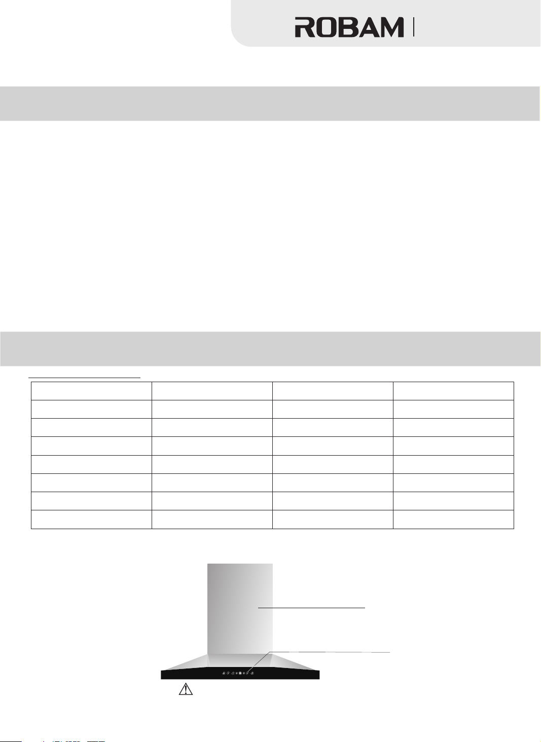
Figure 1
Noise
≤57.5dB
204W
200W
≤4W
A809:895×524×597(mm)
A818:895×504×652(mm)
A809:25.5kg
A818:26kg
≥96%
Decorative pa nel
A818
Contents indicated by are warnings. Failure to follow the instructions will cause danger.
CXW-20 0-8302
Switch
1
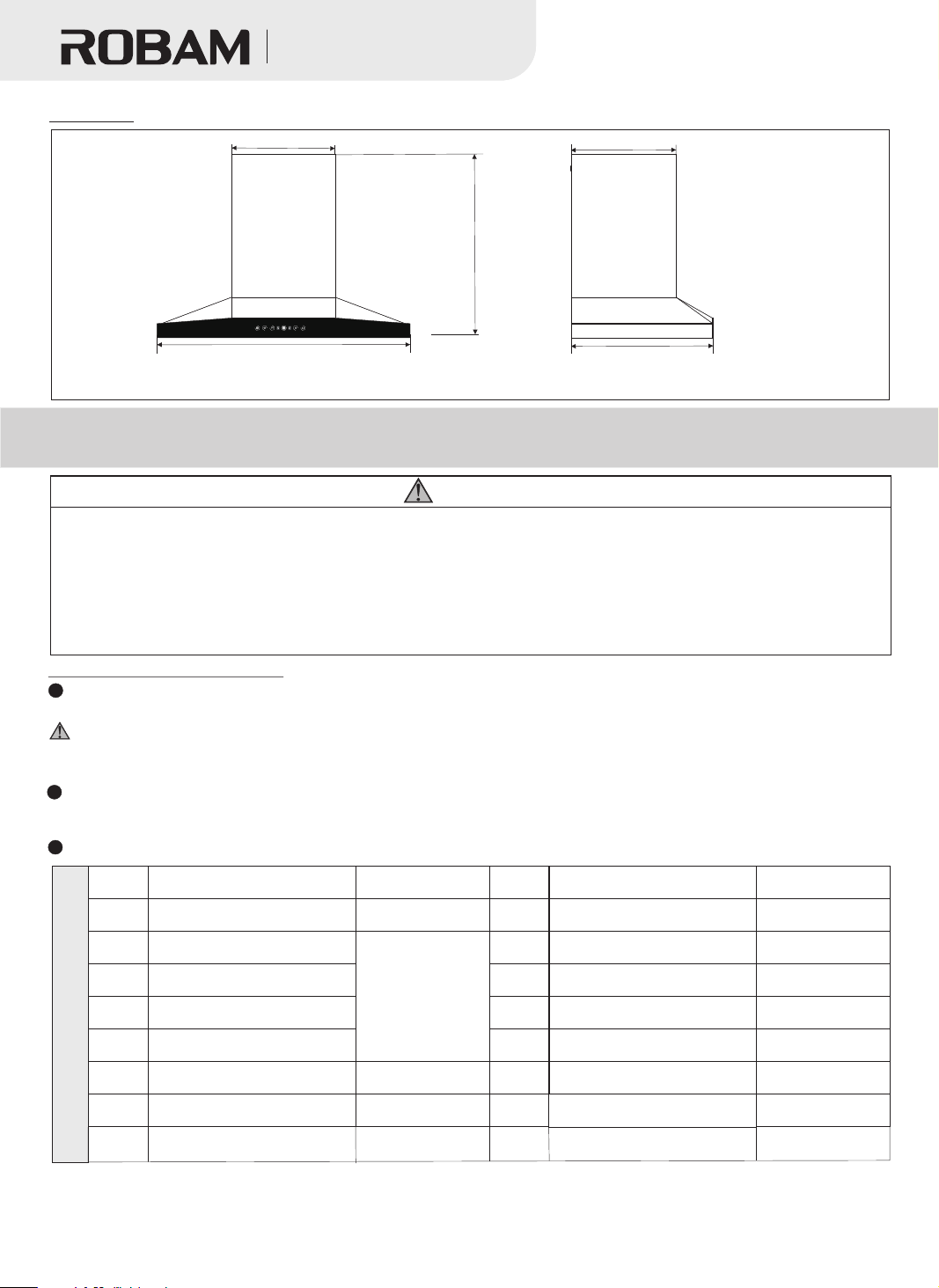
Body Size
Figure 2
吸油烟机
Range Hood
368
372
652( 597)
A818
895
The marked size s are for refer ence only. Size i n the brackets is s pecific to A80 9 hood. (Unit: mm )
CXW-200-8 302
504(524)
Installation Instructions
Warning
1. Flue gases shall not be discharged to the hot flue, which is exclusively used for discharging the combustion gas or
other fuel fumes.
2. Note that when installing the metal expansion pipe, the pipe shall match perfectly with the hole in size.
Overlarge hole is prohibited, as it will result in loose pipe and accidental drops.
3. If the hood is used together with a cooking hob burning gas or other fuels, the room must be well ventilated.
4. Flue diameter smaller than that of the exhaust pipe will affect the hood efficiency. So will overlong exhaust pipe.
5. Regulations concerning the discharge of air have to be fulfilled.
Preparation for Installation
Surroundings
Keep the hood away from too many doors and windows, so as to avoid air convection affecting the efficiency.
The hood is for daily household use. Please do not operate it in special circumstances (e.g. outdoor), nor
use it to discharge hazardous or explosive substances or gases. Before installation, the product shall be placed
in a dry and ventilated place without corrosive and harmful gases.
Tools
The hood will be installed with the following tools: 1). an impact drill (with drill bit); 2). a wrench;
3). a screwdriver; and 4). a ruler.
Check the items in the box
No.
1
Φ175 (OD) aluminum exhaust
2
Packing List
Note: The re are 2 oil cups pro vided, one as spa re oil cup and th e other to be insta lled on the hood. W hen
using the hood, i nstall the cu p on the filter mes h.
pipe
Φ175 (OD) exhaust pipe joint
3
Fixed bar for exhaust pipe
4
5
6
7
8
Exhaust pipe tape
Plastic expansion pipe
Operating Instructions
Name
Hood
Envelope
Quantity
1 piece
1 set
4 pieces
1 piece
1 piece
No.
9
ST4×18 self-tapping screw
10
ST4.8×50 wood screw
11
12
13
14
15
Hitching foot stopper
M6 metal expansion pipe
Name
Check valve
Hitching foot
Oil cup
Quantity
1 set
10 pieces
4 pieces
1 piece
1 pair
1 piece
2 pieces
2
 Loading...