

Page 1
Service Manual
- DVR-9100
R
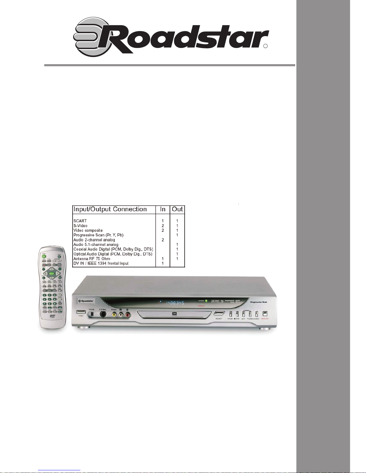
DVR-9100
Service Manual
- DVR-9100
Page 2

S
S
e
e
e
r
r
r
v
v
v
i
i
i
c
c
c
e
e
e
M
M
M
a
a
a
n
n
n
u
u
u
a
a
a
l
l
l
D
D
D
V
V
V
D
D
D
+
+
+
R
R
R
W
W
W
R
R
R
e
e
e
c
c
c
o
o
o
r
r
r
d
d
d
e
e
e
r
rr
S
S
S
y
y
y
s
s
s
t
t
t
e
e
e
m
m
m
caution
Many electrical and mechanical parts in this chassis have special safety characteristics. These safety
characteristics often pass unnoticed and the protection afforded by them can not necessarily be obtained b
y
using replacement components rated for higher voltage, wattage, etc. Replacement parts that have these
special safety characteristics are identified in this manual and its supplements; electrical components
having such features are identified by in the schematic diagram and the parts list.
Before replacing any of these components, read the parts list in this manual carefully. The use of substitute
replacement parts that do not have the same safety characteristics asspecified in the parts list may create
Page 3

1
CONTENTS
SPECIFICATIONS ........................................................................................
ADVANTAGES OF THISRODUCT....................................................................
TROUBLE SHOOTING ...................................................................................
WAVEFORMS ...............................................................................................
VOLTAGE CHARTS........................................................................................
CIRCUIT DIAGRAM.......................................................................................
BLOCK DIAGRAM..........................................................................................
PCB CIRCUIT BOARD....................................................................................
INSTRUMENT DISASSEMBLY........................................................................
02
03
04
25
28
32
46
47
72
Page 4
2
SPECIFICATIONS
Power Supply AC 110V~230V / 50~60Hz
Power Consumption 15~40W
TV Signal System Standard PAL System
Laser Semiconductor Laser,650nm
Operating T emperature
41~95
Operating Humidity 5%~85%
Operating Altitude -305~3048m
Video Output Level
1V±0.2Vpp
DVD Record Media DVD+RW,DVD-R
DVD Playback DVD+RW , DVD+R , DVD-R Video Mode ,
DVD-RW Video , CD , CD-R , CD-RW , VCD ,
CD-DA(CD-Digital Audio) , SVCD(Super Video CD)
Signal Source TV / CVBS / S-Video
Chapter Creation Manually / Automatically
Audio Format 2 ch
Aspect Ratio 4:3 / 16:9 / Full Screen
Luminance Nonlinearity Distortion
≤ 5%
Luminance Wave Distortion (Pulse,Bar)
≤ 10%
Luminance S/N Ratio
≥ 60
Chrominance S/N Ratio
AM ≥ 60 , PM ≥ 55
Chrom Lum Time Delay (Pulse,Bar)
≤ 60ns
DGDP
≤ 5%
Video Recording Grade 1.691 / 2.537 / 3.382 / 5.073 / 9.716 Mbs
Page 5

3
ADVANTAGES OF THIS PRODUCT
Playable Disc Formats
DVD-Video
(single-sided/single-layer,single-sided/double-layer,double-sided/single-layer,double-sided/double-layer)
DVD+RW , DVD+R , DVD-RW , DVD-R
Video-CD (1.0,1.1&2.0) SVCD , CD-DA , Mixed CD-DA (which is mixed data and audio)
DTS encoded Audio CD
MP3 Audio CD (generated by CD-R or CD-RW)
WMA Audio CD (generated by CD-R or CD-RW)
JPEG file disc
Kodak Picture disc
DVCD disc
Feature
Support upgrading mpeg f/w via CD-R/CD-RW
Recordable Disc
DVD+RW , DVD+R
Playback Functions
Normal Playback
Pause/Step Forward(VCD,SVCD,DVD)
Slow Forward/Reverse(VCD,SVCD,DVD)
Recording Function
Real-time recording of live TV input
Recording TV input at a given time and date
Recording audio/video material from camcorder, analog VCR or other A/V source
Simple video editing
Create home-based DVD discs that can be played on existing DVD players
Search Functions
Scan Forward/Reverse
Skip Forward/Reverse
Navigati on Funct ions
Title Menu
DVD Menu
Changeable multilingual audio track
Changeable multilingual subtitle and subtitle toggle
Changeable multi-story, multi-angle, parental control
Program Playback Functions
VCD 1.0, 1.1 &2.0 without PBC, SVCD & CD-DA
Maximum of 99 programmable tracks
Page 6
4
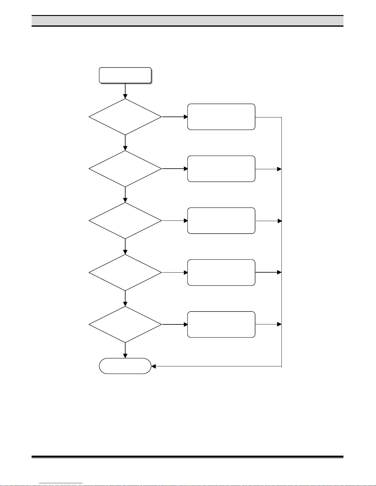
TROUBLE SHOOTING
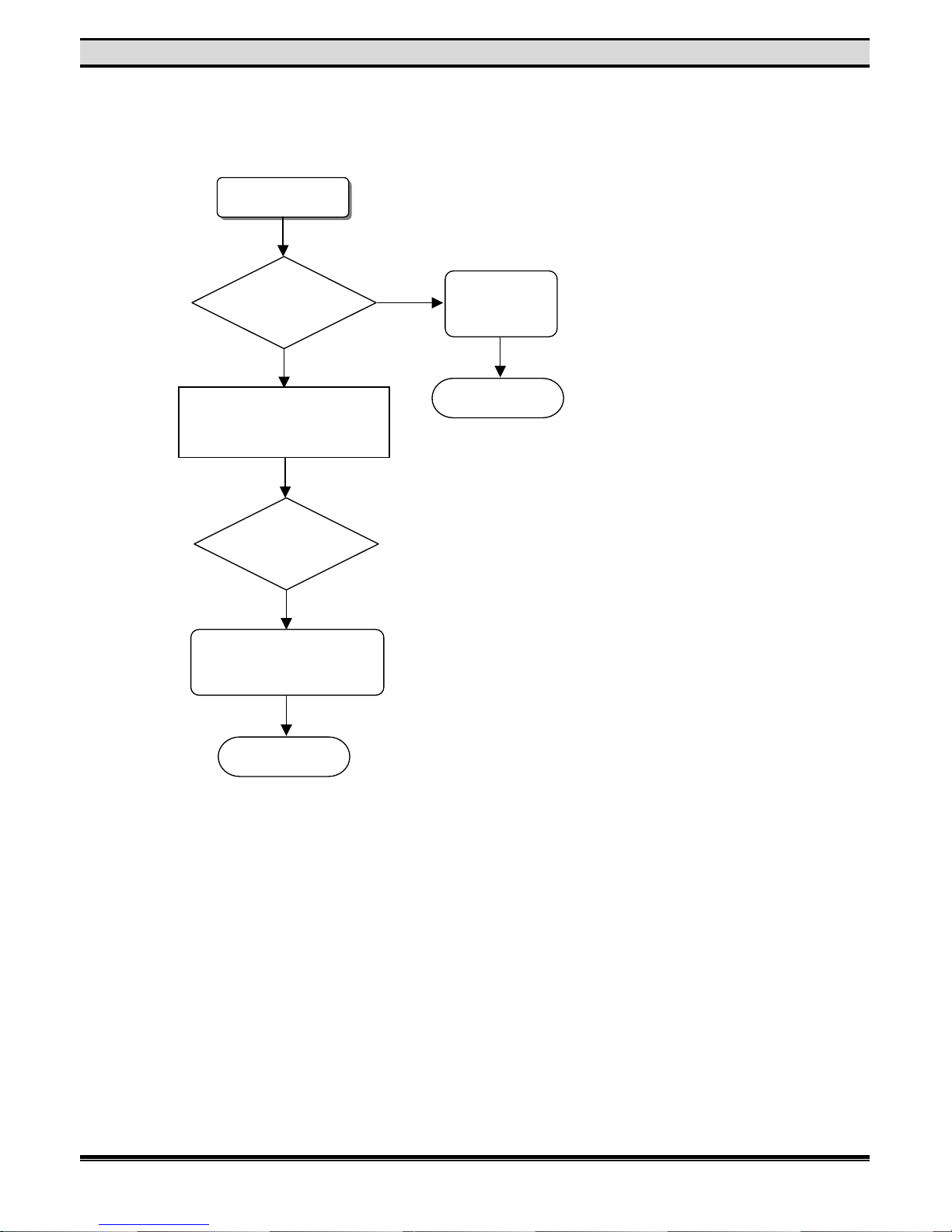
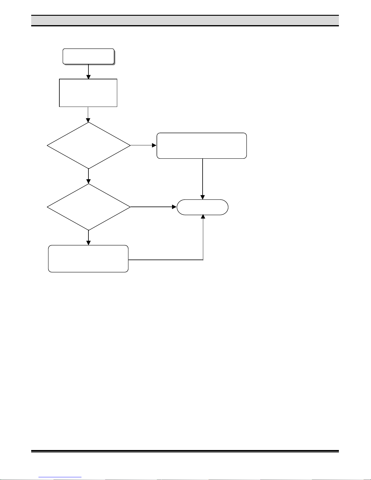
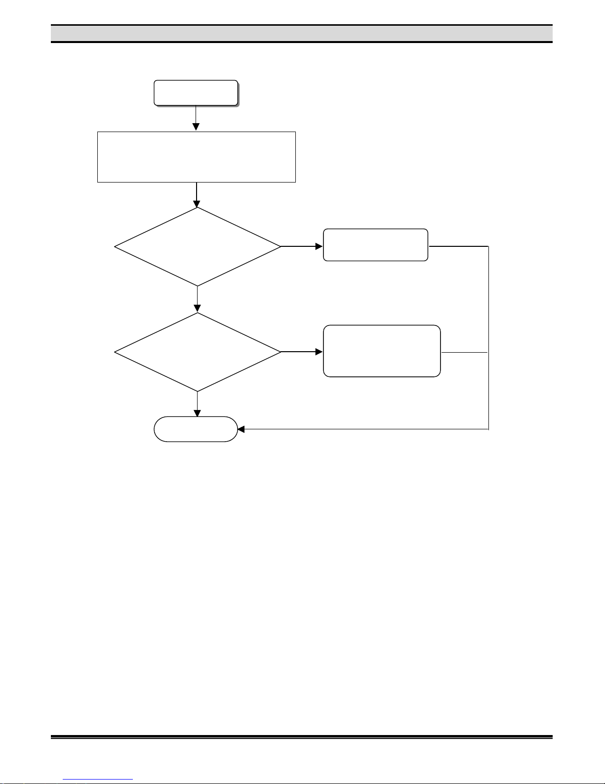
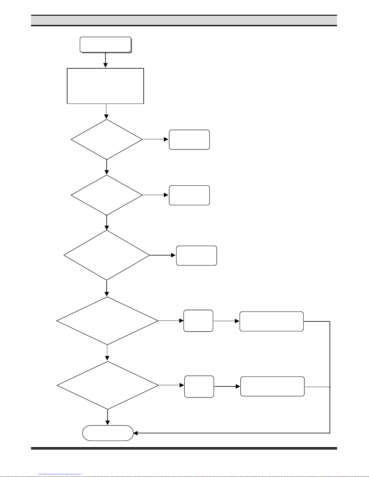
1. POWER TEST
A. Power Board Test
N
o Power
Measure if 5V is
correct ?
Change Power Board
Measure if 3.3V
is correct ?
Change Power Board
Measure if AC3.9
is correct ?
Change Power Board
Measure if -27V
is correct ?
Change Power Board
Measure if 12V
is correct ?
Change Power Board
OK
N
o
Yes
Yes
Yes
Yes
Yes
NoNoNoN
o
Page 7
5
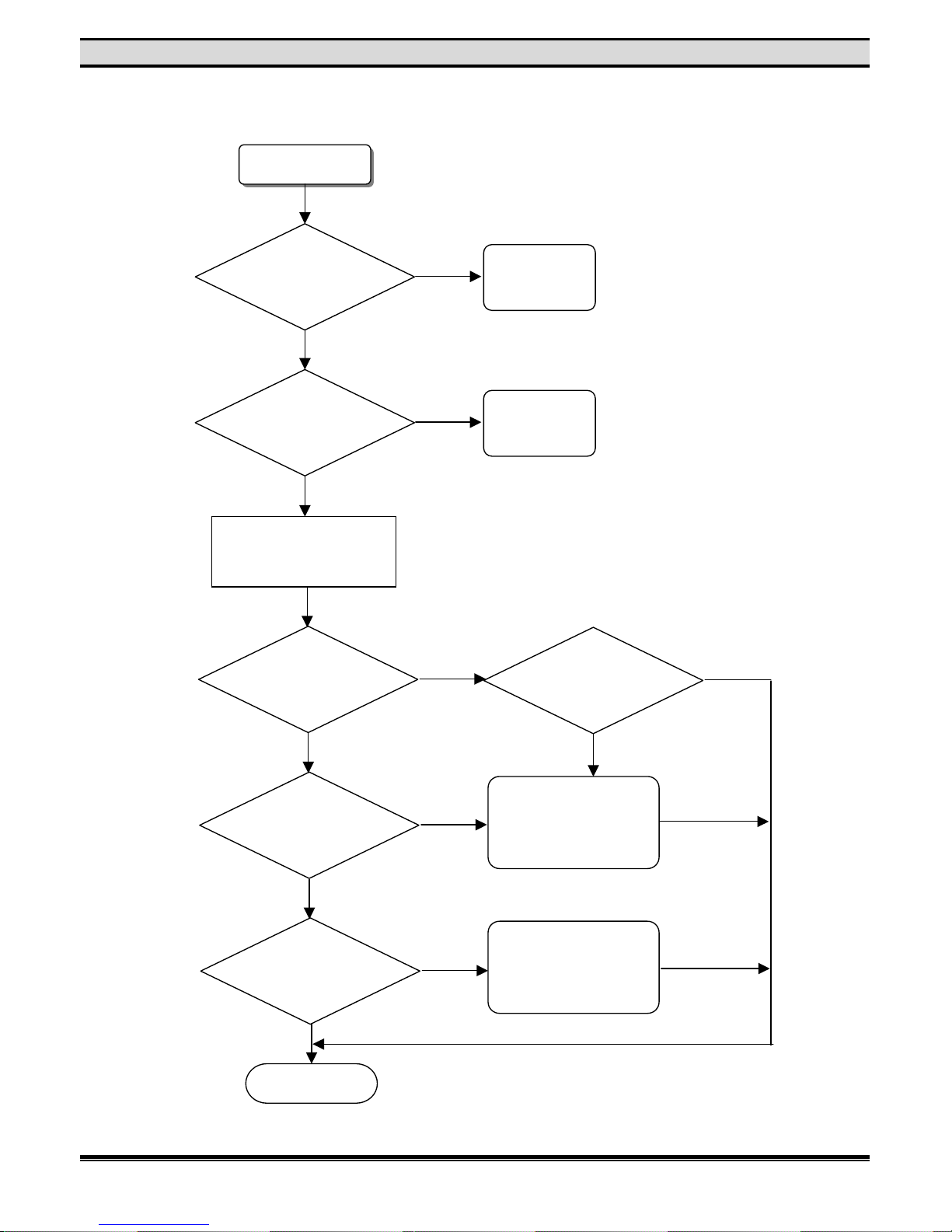
TROUBLE SHOOTING
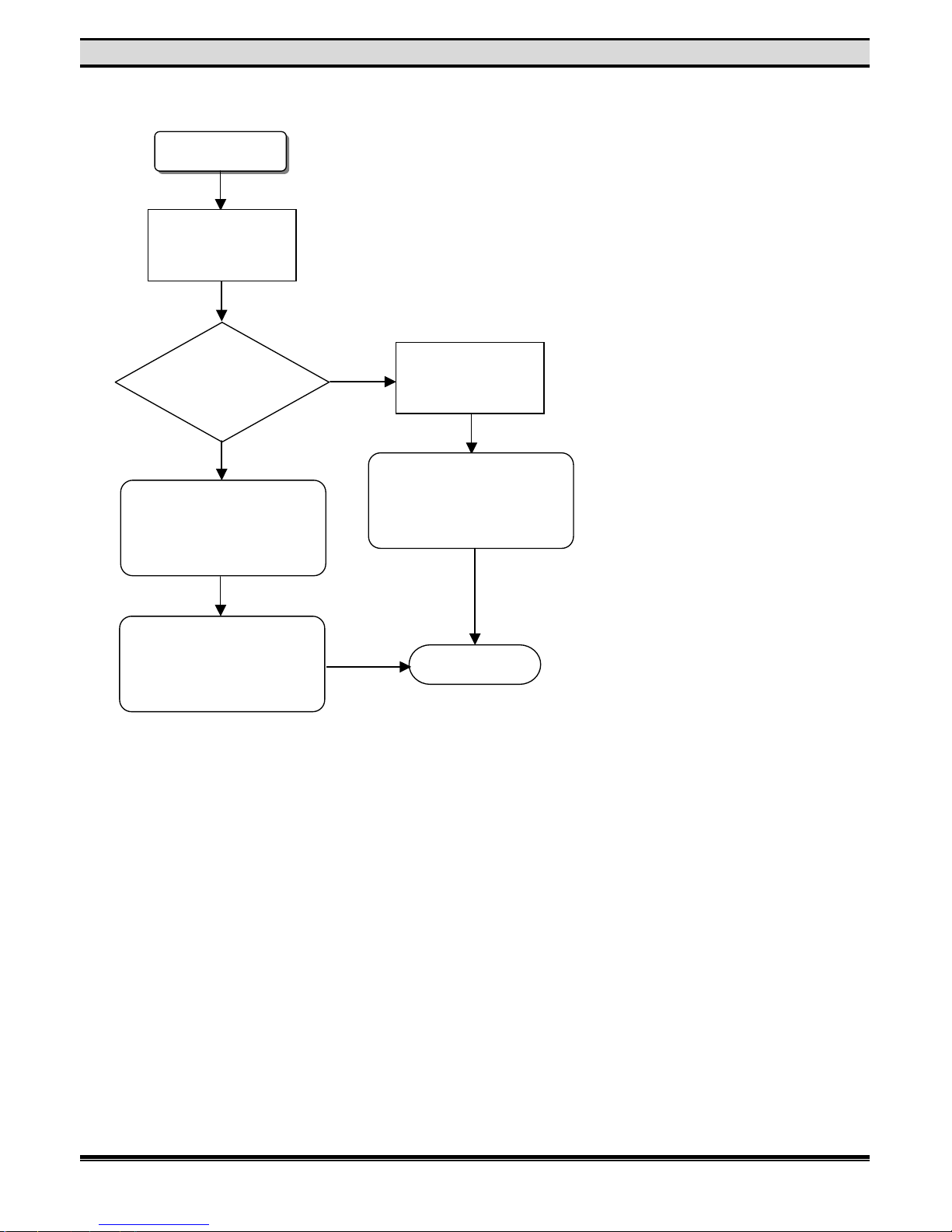
B. Power LED or VFD p anel error
Front board LED
b
roken or contrary
polar ?
No LED display
Change LED
Change
VFD panel
VFD panel broken
or pin shot ?
12 pins cable between
front board and main
board is connected well.
F/B IC U1
#27 is –27v? #17,38 is 5v?
#40 is low voltage?
Are there signals
outputting form IC U1
#15~26,28,29
on F/B?
Are there singles
outputting form IC U34
#195~197
on M/B?
OK
Are there signals
inputting to IC U1
#5,6,8,9
on F/B?
Change F/B IC U1
Change M/B IC U25
else change M/B
Yes
N
o
N
o
Yes
N
o
Yes
N
o
Yes
N
o
Yes
N
o
Yes
Page 8
6
TROUBLE SHOOTING
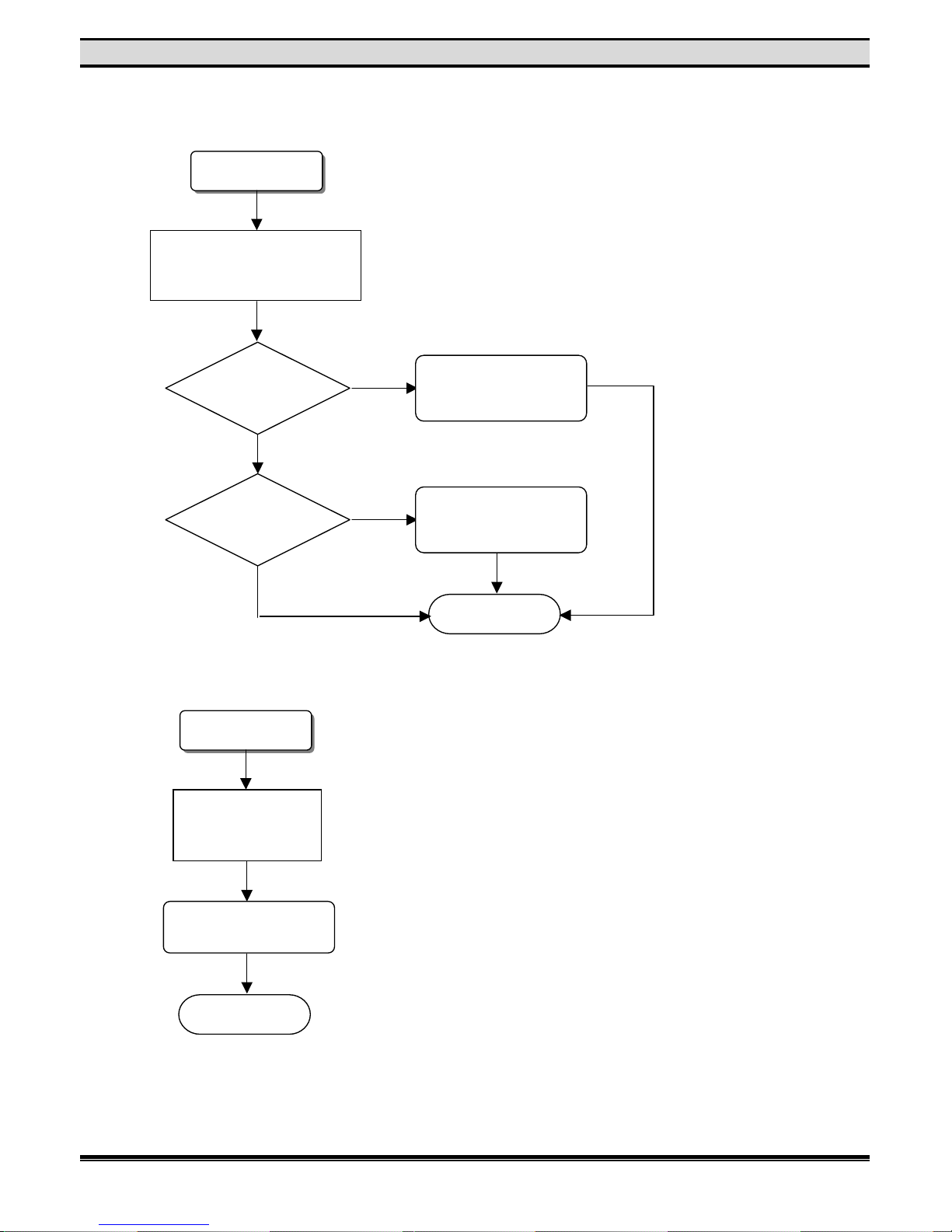
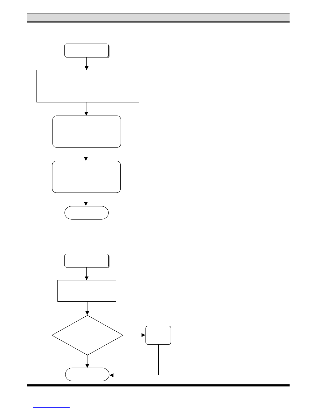
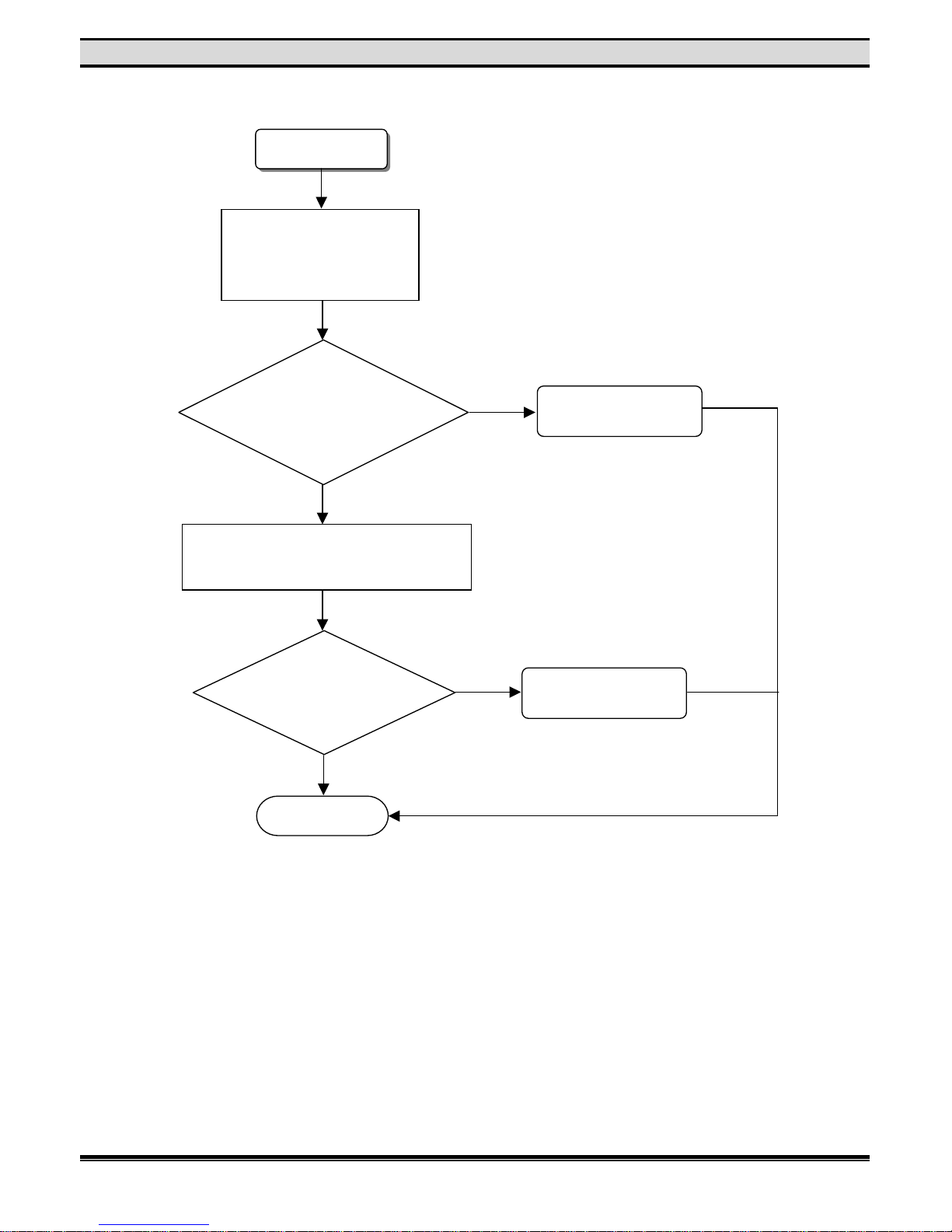
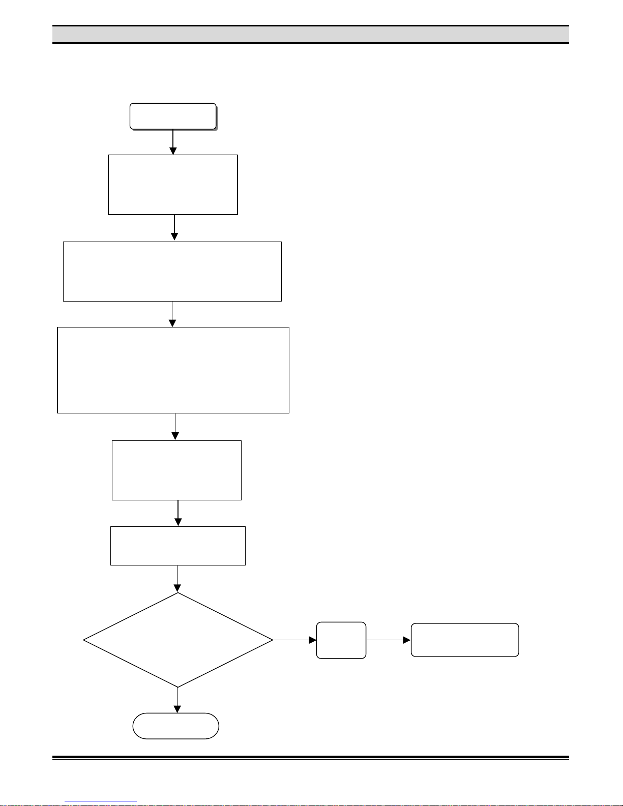
2. PLAYBACK TEST
A. Loading Time Too Long
Loading error
40 pins
cable between M/B
and DVD loader is
connected well?
Change M/B
IC U25
Check resisters had contact
that near M/B IC
U8,U9,U25,U34.
If loading error.
Change M/B IC U25
or
Change M/B
OK
OK
N
o
Yes
Yes
Page 9
7
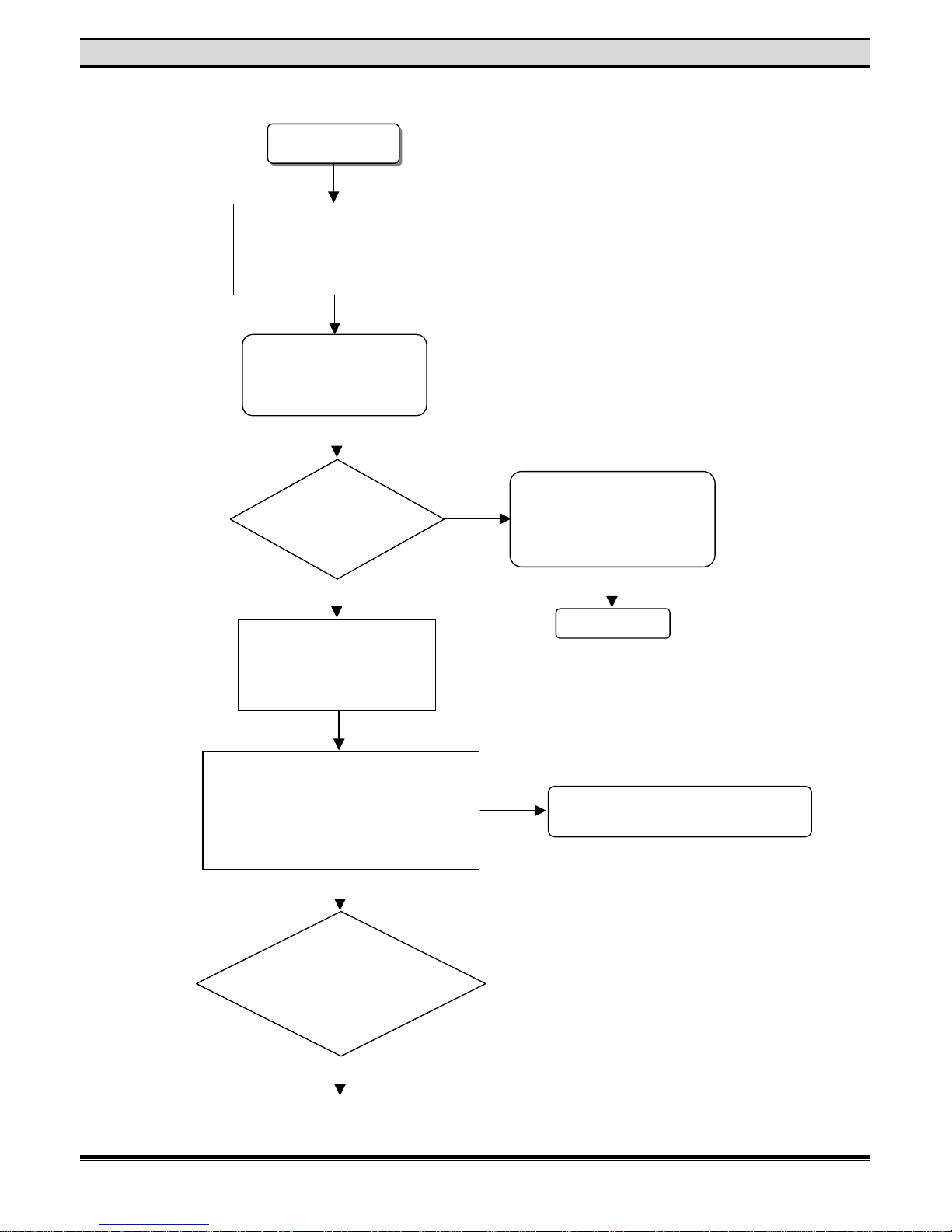
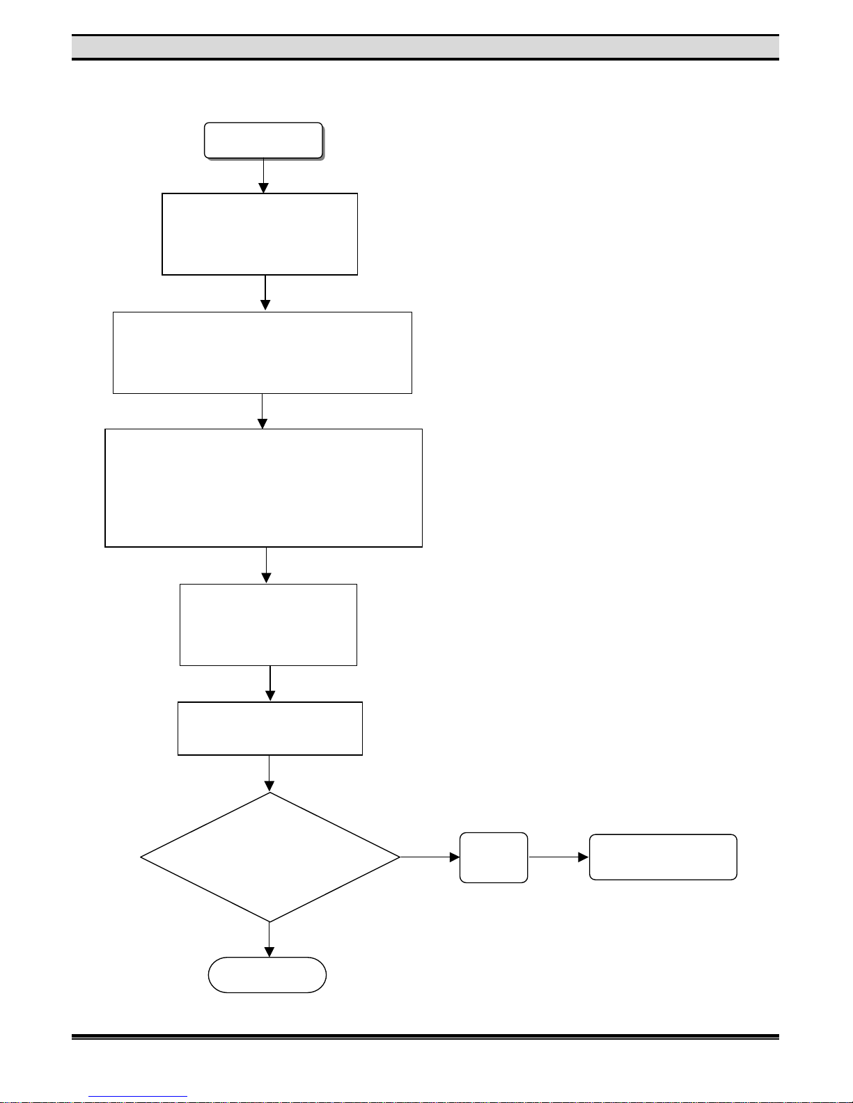
TROUBLE SHOOTING
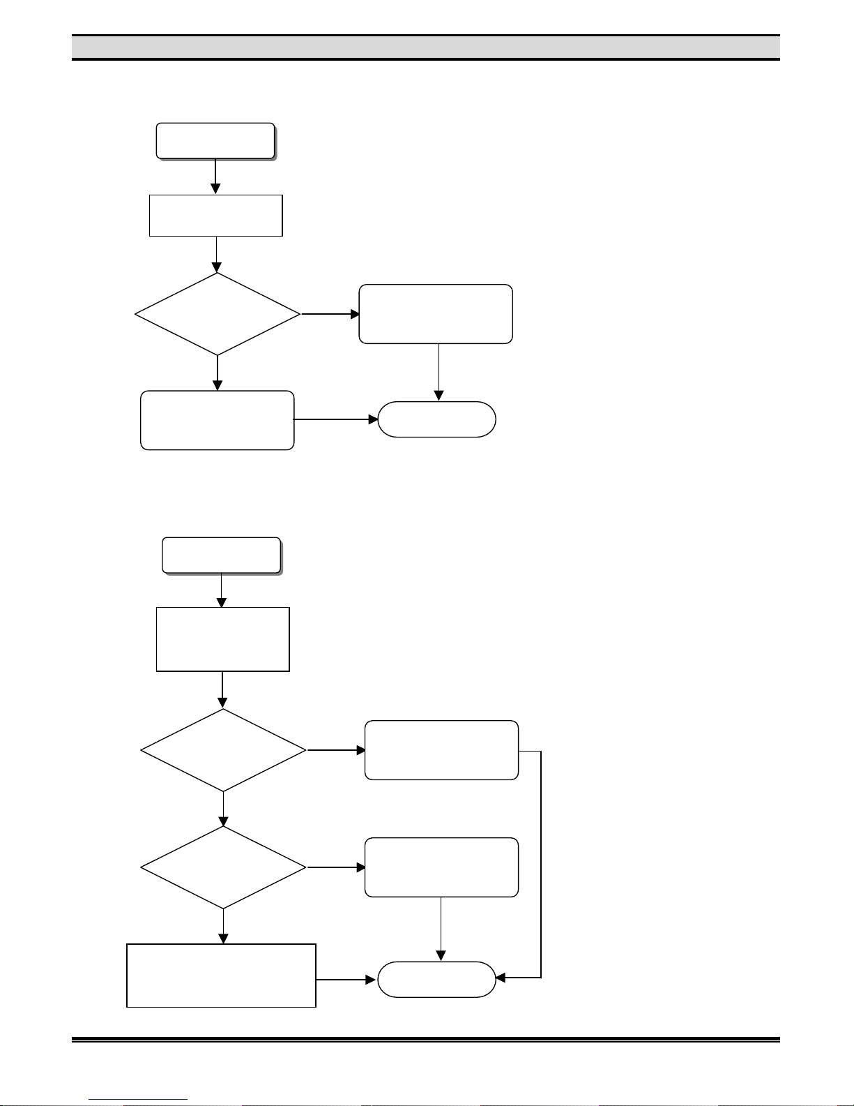
B. Remote Control Not Working Properly
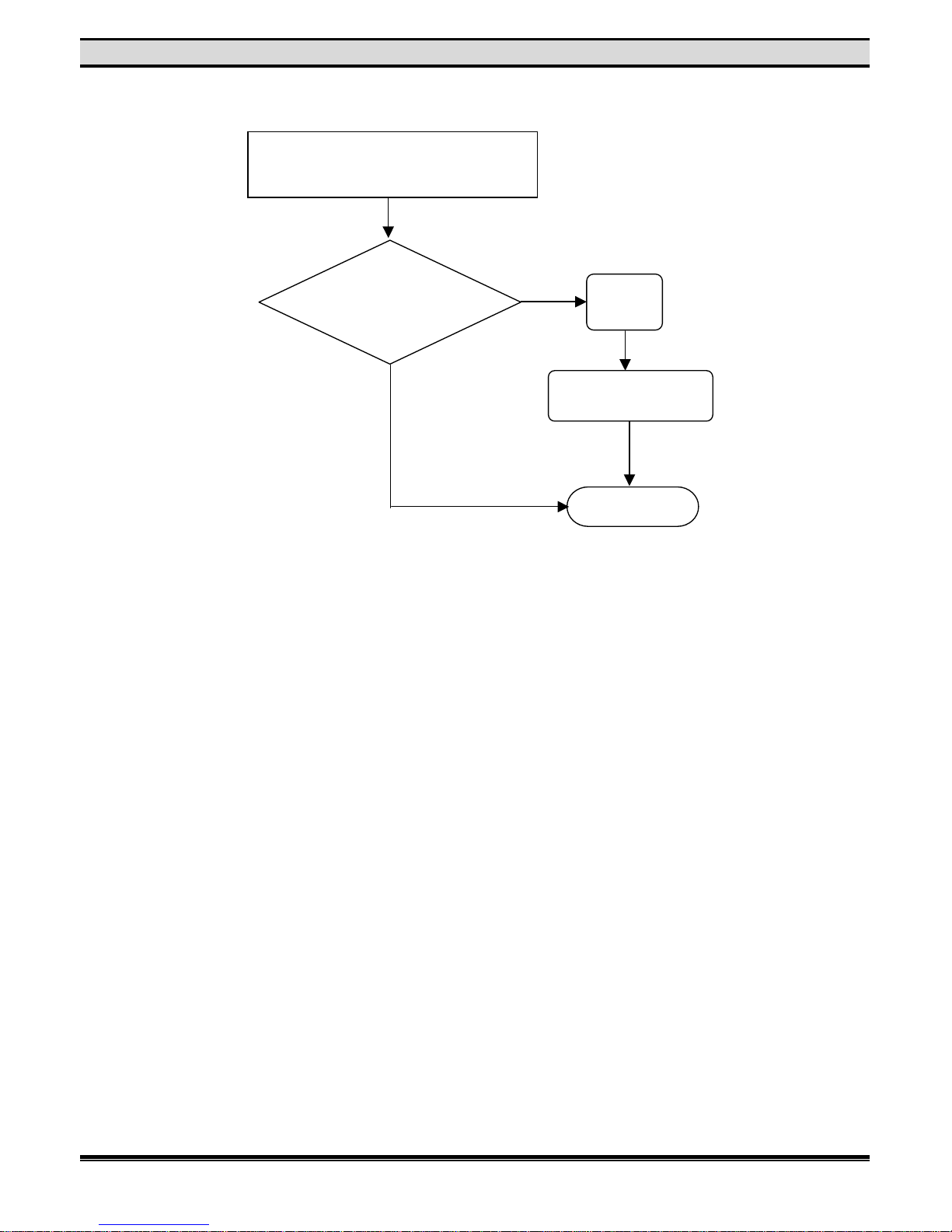
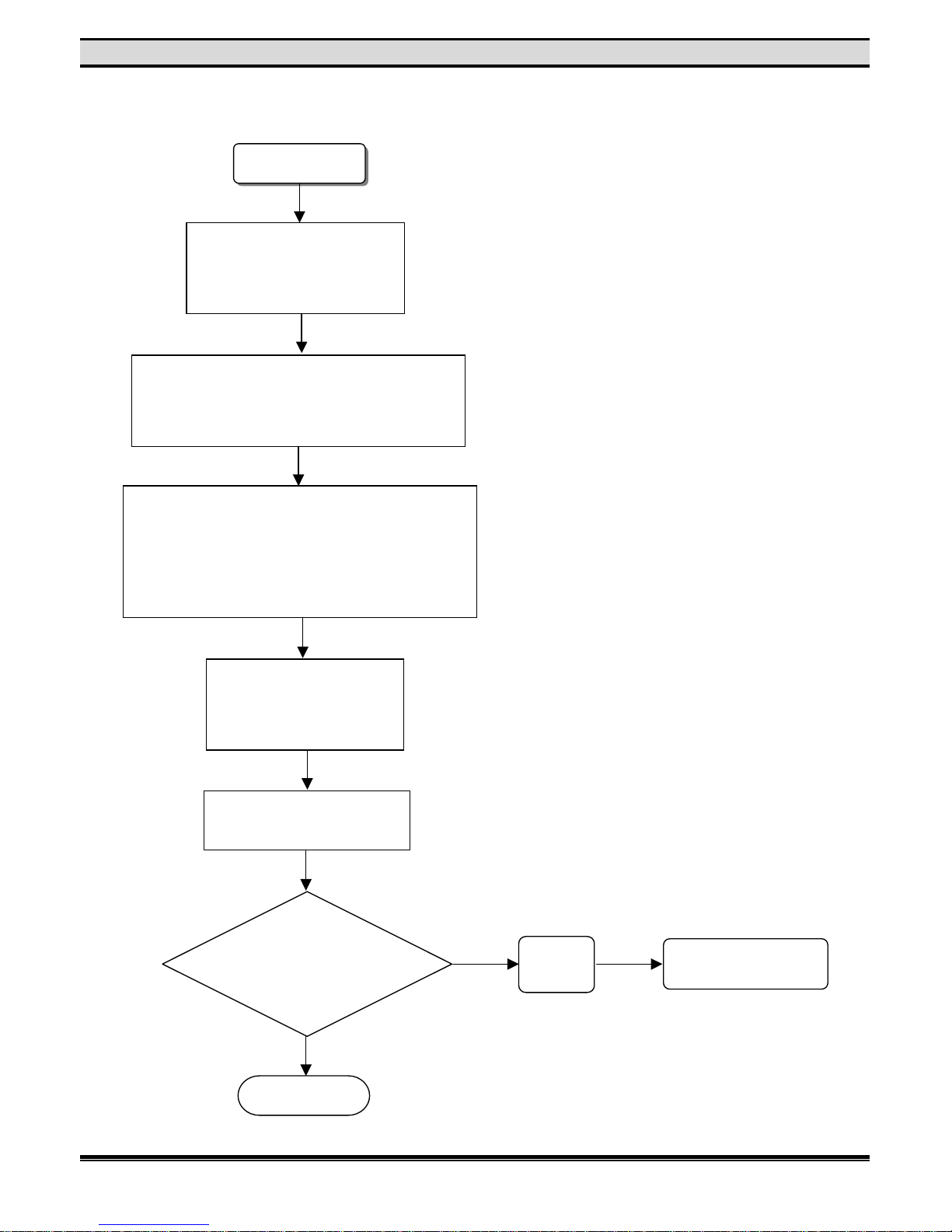
C. System hangs when power on or during playback
Remote Control
error
Check batteries of remote
control are good.
If M/B IC U34
#4 is 5V
Change M/B IC U34
If
F/B IR receiver
U3 #1 is 5V & #3 is
outputting
signal
Change F/B U3
else change F/B
OK
System unstable
Check all cables are
in correct position.
Change M/B IC U25
else change M/B
OK
N
o
Yes
N
o
Yes
Page 10
8
TROUBLE SHOOTING
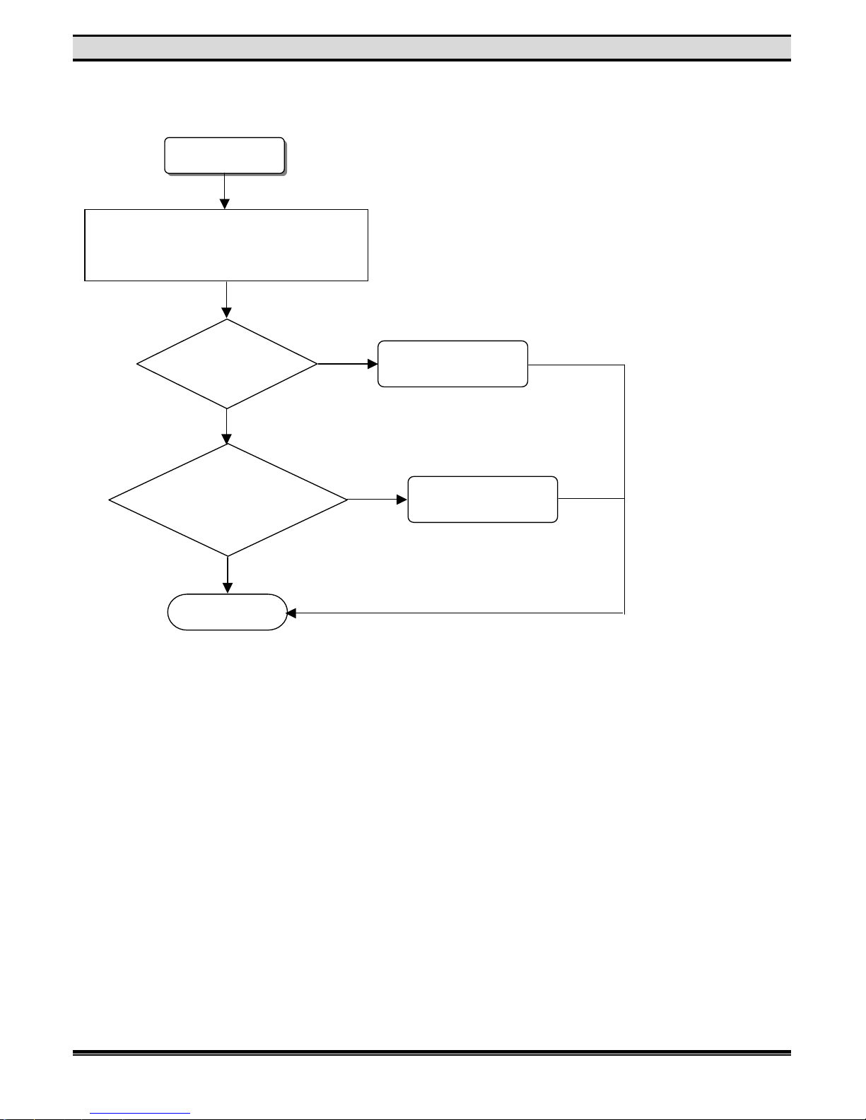
D. Power on noise or noisy loader
E. Reading DVD test discs N.G. or loader doesn’t function, scratches disc or bad
readability.
System noise
Check noise source
If noise is from
loader
Change loader
Change M/B
OK
The loader
can’t work
Check all cables are
in correct position.
If
M/B IC U25’s
firmware is the newest
version
Update M/B’s
firmware
else change M/B
Check resisters had contact
that near M/B IC
U8,U9,U25,U34 & J29.
If
Loader’s
firmware is the newest
version
Update loader’s
firmware
else change loader
OK
N
o
Yes
N
o
Yes
N
o
Yes
Page 11
9
TROUBLE SHOOTING
3. VIDEO TEST
A. No signal input
N
o signal input
Check all cables are
in correct position.
Check M/B J3
& J29 for proper
soldering.
Check M/B IC U34
#151,154,157,160~162,205,208,211
whose 2 parts RLC for proper soldering
nd
If M/B IC U19
#5 is 27MHz
Change U19
Check connectors J4,J7 & J37 on the I/O
board or any resistors, capacitors, & filter
beat near these connectors for short
circuits and bad solderin
g
.
OK
N
o
Yes
Page 12
10
TROUBLE SHOOTING
B. AV input signal-no video output images or abnormal video output
AV input signal
error
Check all cables are
in correct position.
Check
J45 or U2
on the main board or any
resistors for
short circuit
Inspect the whole process
again according to procedure
B on Item 3
If the above actions
don’t work
Check pin 76 & pin 78~80
on U101 for short circuits.
OK
N
o
Yes
N
o
Yes
Page 13
11
TROUBLE SHOOTING
C. TV tuner input-no video output images or abnormal video output
TV input signal
error
Use TV cable or
signal generator to
input TV signals.
Measure
the voltage on pin5
and pin6 on U103 with a
multimeter if it’s 5v or
32v
There’s a 5v
but no a 32v
Check the resistors,
capacitors and inductors
near U103 for short circuits
or bad soldering.
Check positions U3, U2 or U7
on the main board or any
resistors near the IC for short
circuit or bad soldering
Inspect the whole process
again according to
procedure B on item 3.
OK
N
o
Yes
Page 14
12
TROUBLE SHOOTING
D. S-video input-no video output or abnormal video output or black and white video
E. Abnormal VCD/DVD/NF-200 im age or abnorm al displ ay of su btit le or abnorm al menu
selections display.
S-video signal
error
Check the S-video input/output cable to
see if it’s in the right position and secured
to the socket. Black and white images may
b
e caused be caused to the socket.
Check positions J37 & U2 on
the main board or any
resistors near the IC for short
circuit or bad soldering
Inspect the whole process
again according to
procedure B on item 3.
OK
Display error
Check
positions U8, U9 &U34
or any resistors & capacitors near
the IC for short circuit or
bad soldering.
Check positions J3 &
J29 for bad soldering
and short circuits.
OK
Repair
N
o
Yes
Page 15
13
TROUBLE SHOOTING
4. AUDIO TEST
A. Left and Right channel not functioning normally
Left & Right channel
error
Check positions J3, U12~U15 on the main
board or any resistors and capacitors near
the IC for short circuits and bad soldering.
If the main
board & I/O board
are properly connected
to
g
ether
Check
positions J1 & J36 on
the I/O board or any resistors
or capacitors nearby for short
circuit or bad
soldering.
OK
Change main board
Change I/O board
N
o
Yes
N
o
Yes
Page 16
14
TROUBLE SHOOTING
B. The sound of AC-3 or SPDIF not functionally normally
Sound of AC-3
or SPDIF error
Check positions J3, U12~U15 on the main
board or any resistors and capacitors near
the IC for short circuits and bad soldering.
Check
positions J1 & J36 on
the I/O board or any resistors
or capacitors nearby for short
circuit or bad
soldering.
Check
If settings of an
Amplifier are correct? Check line
between amplifier and the
unit are connected
properly.
OK
Change I/O board
Replace the connection
or setup the amplifier
correctly.
N
o
Yes
N
o
Yes
Page 17
15
TROUBLE SHOOTING
C. No sound in R/L audio inputs or abnormal sound.
R/L audio error
Check the flat cable
connected to the main
board to see if it’s secured
to the right socket.
Check
positions J3,J45,
U12~U15,U20,U21,U24
on the main board or any resistors
or capacitors nearby for short
circuit or bad
soldering.
Check if the main board and I/O board are
p
roperly connected together (check if the
pin assignments are correctly connected.)
Check
positions J1 & J36 on
the I/O board or any resistors
or capacitors nearby for short
circuit or bad soldering
or damage.
OK
Change I/O board
Change main board
N
o
Yes
N
o
Yes
Page 18
16
TROUBLE SHOOTING
D. The sound of TV-tuner audio L/R channel not functionally normally
R/L audio error
Check the flat cable
connected to the main
board to see if it’s secured
to the right socket.
Use TV cable or signal
generator to input TV
signal.
Measure
the voltage on pin5
and pin6 on U103 with a
multimeter if it’s 5v or
32v
Check the resistors,
capacitors and inductors
near U103 for short circuits
or bad soldering.
Check positions U3 and JP1
on the main board or any
resistors near the IC for short
circuit or bad soldering.
Use the oscilloscope to measure the voltage
output on p in6 &pin7 on JP 1. The range o
f
the voltage is between 2~2.3V.(This is the
standard value; need to compare the value
with the customer’s request. So far, there’s
another value about 1V.
Check
positions J3,J45,
U12~U15,U20,U21,U24
the main board or any resistors
or capacitors nearby for short
circuit or bad
soldering.
Change U103
Change the TV-tuner board on JP1
N
o
Yes
Yes
Page 19
17
TROUBLE SHOOTING
Check if the main board and I/O board are
properly connected together (check if the
pin assignments are correctly connected.)
Check
positions J1 & J36 on
the I/O board or any resistors
or capacitors nearby for short
circuit or bad
soldering.
Repair
Change I/O board
OK
N
o
Yes
Page 20
18
TROUBLE SHOOTING
E. TCD-731 or SBC444A or CBS or MP3 not sounding normally
Audio error
Check the flat cable
connected to the main
board to see if it’s secured
to the right socket.
Check
if the frequency
of pin5 on U19 located
on the main board
27 MHz
Change U19
Check
if the frequency
of pin64 on U34 located
on the main board
120MHz
Change U34
Check
if the frequency
of pinA19 & pinc17 on
U90 located on the
main board
108MHz
Change U90
Check
positions J12, J13, U34
and any resistors
or capacitors near the IC
for bad
soldering.
Repair
Check
positions J1 & J36 on
the I/O board or any resistors
or capacitors nearby for short
circuit or bad soldering
or damage.
OK
Repair
Change main board
Change I/O board
N
o
Yes
N
o
Yes
N
o
Yes
N
o
Yes
N
o
Yes
Page 21
19
TROUBLE SHOOTING
5. RECORD TEST
A. AV input can’t record
AV input can’t
record
Check AV cord between
source unit and DVD-R100
is connected properly or
replace AV cord.
Check if the disc is a DVD+R or DVD+RW
disc and there’s space available for recording.
The data inside a DVD+RW disc can be
erased usin
g
the function ke
y
A disc can record only one kind of format of
data(NTSC/PAL). Check the format of data that’s
already recorded on the disc(this is not necessary
if the disc is new). A new disc must be formatted
before use. This usually takes 2~3 minutes.
Check the flat cable
connected to the main
board to see if it’s secured
to the right socket.
Make sure the JUMP on J38
is inserted.
Check
positions U29
U70, U90, U99
on the main board or any resistors
or capacitors nearby for short
circuit or bad
soldering.
OK
Repair
Change main board
N
o
Yes
Page 22
20
TROUBLE SHOOTING
B. S-video input can’t record
S-video input
can’t record
Check S-video cord between
source unit and DVD-R100 is
connected properly or replace
AV cord.
Check if the disc is a DVD+R or DVD+RW
disc and there’s space available for recording.
The data inside a DVD+RW disc can be
erased using the function key
A disc can record only one kind of format of
data(NTSC/PAL). Check the format of data that’s
already recorded on the disc(this is not necessary
if the disc is new). A new disc must be formatted
before use. This usually takes 2~3 minutes.
Check the flat cable
connected to the main
board to see if it’s secured
to the right socket.
Make sure the JUMP on J38
is inserted.
Check
positions U29
U70, U90, U99
on the main board or any resistors
or capacitors nearby for short
circuit or bad
soldering.
OK
Repair
Change main board
N
o
Yes
Page 23
21
TROUBLE SHOOTING
C. TV-tuner input can’t record
TV-tuner input
can’t record
Check coaxial cable between
source unit and DVD-R100 is
connected properly or replace
AV cord.
Check if the disc is a DVD+R or DVD+RW
disc and there’s space available for recording.
The data inside a DVD+RW disc can be
erased using the function key
A disc can record only one kind of format of
data(NTSC/PAL). Check the format of data that’s
already recorded on the disc(this is not necessary
if the disc is new). A new disc must be formatted
before use. This usually takes 2~3 minutes.
Check the flat cable
connected to the main
board to see if it’s secured
to the right socket.
Make sure the JUMP on J38
is inserted.
Check
positions U29
U70, U90, U99
on the main board or any resistors
or capacitors nearby for short
circuit or bad
soldering.
OK
Repair
Change main board
N
o
Yes
Page 24

22
TROUBLE SHOOTING
6. FUNCTION TEST
A. Image can’t stop or mute, fast forward and fast forward key don’t function
Image function
error
If the machine is functioning
normally, check the battery in the
remote control. Change the battery
if necessary.
Check U34 and any
components nearby for bad
replace it with a working
F/W, check if the machine
will function normally.
Remove F/W (U25) and
replace it with a working
F/W, check if the machine
will function normally.
Check IR receiver U3 and
any resistors near U3 for
bad soldering, open/short
circuit, damage, etc.
Check the 12pin cable that
connects the front board with
the main board, check if the
cable is properly connected.
OK
Replace main board
Replace front board
N
o
Yes
N
o
Yes
Page 25

23
TROUBLE SHOOTING
B. Front panel buttons
Front panel
b
uttons
Remove F/W (U25) and
replace it with a working
F/W, check if the machine
will function normally.
Replace main board
Remove the top cover, remove
the panel; check if there’s any
signal output on pin15, 16 of U1
on the front board(also check for
bad soldering)
Check U34 and any
components nearby for
bad soldering, open/short
circuit, damage, etc.
Check SW1~SW7 and any
components nearby for bad
soldering, open/short circuit,
damage, etc.
Check the 12pin cable that
connects the front board with the
main board, check if the cable is
prop
erly connected.
Check the 12pin cable that
connects the front board
with the main board, check
if the cable is properly
connected.
Replace front board
Use the oscillator or multimeter to
check if the voltage between p10
and GND of JP6 on the main
board –27V and also check if the
voltage between pin2 and GND 5V
OK
Replace power board
N
o
Yes
N
o
Yes
N
o
Yes
Page 26

24
TROUBLE SHOOTING
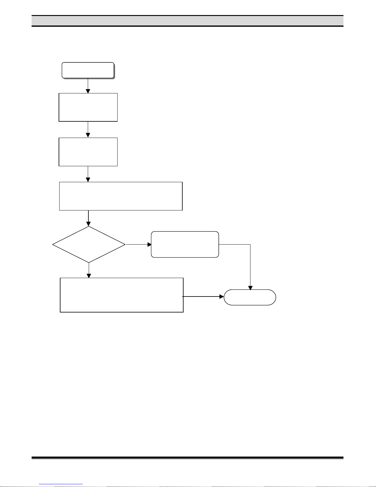
7. SYSTEM TEST
A. Can’t enter system setup or after setup, system hangs or don’t function
System error
Check
components U8, U9 an
d
IC for bad soldering,
etc.
Repair
Replace main board
OK
N
o
Yes
Page 27

25
WAVEFORMS
VIDEO
Composite signal
500mV
250MS/s
(REC)
Composite signal
500mV
250MS/s
(PLAY)
S-video signal (Y)
500mV
250MS/s
(REC)
S-video signal (Y)
500mV
250MS/s
(PLAY)
S-video signal (C)
500mV
250MS/s
(REC)
S-video signal (C)
500mV
250MS/s
(PLAY)
Page 28

26
WAVEFORMS
A/V signal (R)
500mV
5.0GS/s
(REC)
A/V signal (R)
500mV
5.0GS/s
(PLAY)
A/V signal (G)
500mV
125MS/s
(REC)
A/V signal (G)
500mV
125MS/s
(PLAY)
A/V signal (B)
500mV
5.0GS/s
(REC)
A/V signal (B)
500mV
5.0GS/s
(PLAY)
Page 29

27
WAVEFORMS
AUDIO
AOL signal
500mV
1.25MS/s
(REC)
AOL signal
500mV
2.5MS/s
(PLAY)
AOR signal
500mV
500MS/s
(REC)
AOR signal
500mV
2.5MS/s
(PLAY)
Page 30

28
VOLTAGE CHARTS
CS 98201 VOLTAGE CHARTS
CS 98201 (U34)
STO
P REC PLAY
1 1.8 1.8 1.8
2
3.0
2.9
3.0 3 0.0 0.0 0.0
4 4.8 4.8 4.8
5 0.0 0.0
1.5
6
2.9 2.8 2.9
7 0.0 0.1 0.0 8
2.8
0.0
2.8
9 3.0
2.9 2.9
10 1.6 1.6 1.6
11 1.6 1.6 1.6
12 1.5 1.5 1.5
13 1
.
4 1.5 1.5
14
0.0 0.0 0.0
15 1.5 1.4 1.5
16 1.6 1.5 1.6
17
0.0
1.5
0.0
18 1.5 1.5 1.5
19
3.0
2.9 2.9
20 1.5 1.4 1.5
21 1.6 1.5 1.5
22
0.0
1.7
0.0
23 1.5 1.5 1.5
24
0.0 0.0 0.0
25
0.0 0.0 0.0
26 1.5 1.5 1.5
27 1.5 1.4 1.5
28 1.6 1.5 1.6
29 1.6 1.5 1.6
30
1.5 1.5 1.5
31 3.0
2.9 2.9
3
2 1.5 1.4 1.5
33
1.7 1.7 1.7
34 0.0 0.0 0.0 35
1.7 1.7 1.6
36
1.6 1.5 1.6
37
1.6 1.5 1.5
38
1.6 1.5 1.5
39
1.5 1.6 1.5
40 1.6 1.6 1.6
41
3.0
2.9 2.9
42 1.5 1.5 1.5
43
0.0 0.0 0.0
44
0.0 0.0 0.0
45 1.5 1.5 1.5
46 1.7 1.7 1.7
47 1.5 1.5 1.5
MODE
PIN No.
CS 98201 (U34)
STO
PRECPLAY
48 1.61
.51.649
1.61
.61.6
50
1.61
.61.5
5
1 1
.51.51.5
52 0.0
0.0
0.0
53
1.61
.71.6
54 3.02.82.9
55
1.61
.61.6
56
1.51
.51.5
57
1.71
.81.7
58
1.71
.81.7
59
1.81
.91.8
60
1.71
.81.7
6
1 1
.51.51.5
6
2 1
.71.61.6
63 0.0
0.0
0.0
6
4 1
.51.
41
.5
65
2.92
.9
3.0
66
1.71
.61.7
67
1.61
.61.7
68
1.71
.61.7
69
1.71
.71.770
1.71
.71.7
7
1 1
.71.71.7
72 0.0
0.0
0.0
73
1.71
.61.7
7
4 1
.71.71.7
75 0.01.6
0.0
76
1.51
.51.5
77
1.61
.61.6
78
1.61
.51.6
79
1.61
.51.6
80
1.61
.51.6
8
1 1
.71.71.7
8
2 1
.61.61.6
83 0.0
0.0
0.0
84 0.0
0.0
0.0
85
1.61
.61.686 3.02.92.9
87
1.61
.61.6
88
1.61
.61.6
89
1.71
.61.6
90
1.51.41
.5
9
1 1.41
.
41
.49
2 1
.61.61.6
93
1
.
41
.
41
.49
4 1.41
.
41
.4CS 98201 (U34)
STO
P RE
C
PLAY
95
1
.
4 1.41
.496
1
.
4 1.41
.497 0.0 0.0
0.0
98 0.0 0.0
0.0
99
1
.
4 1.41
.
4
100 1.7 1.71
.710
1 1.6 1.51
.610
2 1.8 1.81
.8103
1.8 1.81
.710
4 1.7 1.81
.7105 3.0
2.92
.9106
1.8 1.81
.8107
4.8 4.84
.8108
4.8 4.84
.8109
4.8 4.84
.8110
4.8 4.84
.8
111
3.0 3.02.9
112 4.8 4.84
.8113
2.9 2.92
.9
114
0.0 0.0
0.0115 0.0 0.0
0.0116 0.0 0.0
0.0117 0.0 0.0
0.0118 0.0 0.0
0.0119 0.0 0.0
0.0120
1.8 1.81
.8
121
0.0 0.0
0.0
122
0.0 0.0
0.0123 0.0
1
.5
0.0
124
0.0 0.31.7125 0.0
1.41
.3126 0.0
1.41
.7
127
0.0
1
.5
0.0
128 2.9 2.92
.9129 3.0
2
.9
3.0130 3.0
2.92
.913
1 1.8 1.81
.8132 0.0 0.0
0.0133 0.0 0.01.7134 0.0
1
.5
0.0135 0.0
1
.5
0.0136 0.0
1
.5
0.0137 0.0 0.31.6138 0.0 0.
21
.7139 0.0 0.31.6140 0.0 0.
21
.7
141
0.0
1.51.1
MODE
PIN No.
MODE
PIN No.
Page 31

29
VOLTAGE CHARTS
CS 98201 VOLTAGE CHARTS
CS 98201 (U34)
STO
P REC PLAY
142
0.0 0.3 0.0
143
0.0 0.4 0.0
144
3.0
2.9 2.9
145
0.0 0.0 0.0
146
3.0
2.9 2.9
147 2.9 2.8 2.8
148
0.0 0.0 0.0
149 1.8 1.8 1.8
150
0.0 0.0 0.0
151 1.3 1.4 1.4
152 2.9 2.9 2.9
153
0.0 0.0 0.0
154 1.0 1.0 1.0
155 2.9 2.8 2.9
156
0
.0 0.0 0.0
157 1.1 1.1 1.1
158 2.9 2.9 2.9
159
0.0 0.0 0.0
160 1.8 1.8 1.8
161 1.2 1.2 1.2
162 1.2 1.2 1.2
163
0.0 0.0 0.0
164 2.9 2.9 2.9
165
0.0 0.0 0.0
166 2.9 2.9 2.9
167 2.9 2.9 2.9
168
3.0
2.9 2.9
169 1.7 1.7 1.7
170 2.9
0.0
2.9
171
0.
0 0.0 0.0
172 2.9
0.0
1.5
173 2.9
0.0
1.5
174 2.9 2.9 2.9
175 2.9
0.0
2.9
176
0.0 0.0 0.0
177
0.0
1.6
0.0
178 4.8 4.7 4.7
179 4.8 4.7 4.7
180 1.8 1.8 1.7
181
0.0 0.0 0.0
182
0.0 0.0 0.0
183 4.2 4.2 4.2
184 2.9
0.0
2.9
185
0.0 0.0 0.0
186 2.9 2.9 1.7
187 2.9 2.9 1.7
188 2.9 2.9 2.9
CS 98201 (U34)
STO
PRECPLAY
189 2.92
.92.9190 0.0
0.0
0.019
1 2
.91.52.919
2 2
.91.61.7193 3.02.91.719
4 2
.92.82.9195
2.62
.62.6196
2.02
.02.0197
4.74
.74.8198
2.52
.52.5199 0.01.6
0.0200 0.01.5
0.0201 0.01.6
0.0202 0.0
0.0
0.0203
1.81
.81.7204 0.0
0.0
0.0205
1.31
.31.3206
2.92
.82.9207 0.0
0.0
0.0208
1.11
.
11
.
1
209 2.92
.92.9210 0.0
0.0
0.0
211 1
.31.51.
2
212 2
.92.82.9213 0.0
0.0
0.0
214 1
.81.81.8215
1.21
.
21
.
2
216 1.21
.
21
.
2
217
0.0
0.0
0.0218
2.92
.92.9219 0.0
0.0
0.0220
2.92
.92.9
221 2
.92.92.9
222 1
.61.61.5223
1.71
.71.7
224 1
.61.61.5225 0.0
0.0
0.0226
1.51
.61.5227 0.0
0.0
0.0228 0.0
0.0
0.0229 0.00.01.5230
2.92
.92.923
1 1
.61.71.723
2 1
.61.61.8233 0.0
0.0
0.0234 0.01.61.6235
1.61
.51.6
CS 98201 (U34)
STO
P RE
C
PLAY
236 1.8 1.71
.7237
1.8 1.81
.8238 0.0 0.0
0.0239 0.0 0.0
0.0240 0.0 0.0
0.0
MODE
PIN No.
MODE
PIN No.
MODE
PIN No.
Page 32

30
VOLTAGE CHARTS
EEPROM VOLTAGE CHARTS
CS4362 VOLTAGE CHARTS
N5532A VOLTAGE CHARTS
EEPROM (U2
5)
STO
P REC PLAY
1 1.5 1.5 1.4
2 1.6 1.5 1.5
3 0.0
1.6 1.6
4
0.
1 1.6 1.5
5 0.
1 1.5
0.0 6 0.0
1.5
0.0 7 0.0
1.5 1.5
8 0.0
1.6 1.6
9
1.6 1.5 1.6
10
0.0
1.6
0.0
11
0.0
1.7 1.7
12
0.0
2.9 2.9
13
0.0
1.6 1.6
14
0.
0
2.9 2.9
15
0.0 0.0 0.0
16 1.5 1.5
0.0
EEPROM (U2
5)
STO
PRECPLAY
17 1.61
.51.518 0.01.61.619 0.01.81.720 0.01.71.6
21
0.01.71.7
22 1
.71.61.723 0.01.61.7
24
0.01.71.725
1.71
.61.726
1.71
.71.727 0.0
0.0
0.028
1.71
.71.729
1.51.41
.430 0.0
0.0
0.0
3
1 1
.61.51.6
32 0.0
0.0
0.0
EEPROM (U2
5)
STO
P RE
C
PLAY
33
1
.
4 1.41
.434 0.0 0.0
0.0
35
1.5 1.41
.436 0.0 0.0
0.0
37 3.0
2.92
.9
38
1.5 1.41
.439 0.0 0.0
0.040
1.5 1.41
.
4
41
0.0 0.0
0.0
42 1.5 1.41
.
4
43
0.0
1.4
0.0
44 1.6 1.51
.545
1.6 1.51
.546 0.0 0.0
0.047 0.0 0.0
0.048
1.5 1.61
.5
MODE
PIN No.
MODE
PIN No.
MODE
PIN No.
CS4362 (U12)
STO
P REC PLAY
1
0.0 0.0 0.0
2
0.0 0.0 0.0 3 0.0 0.0 0.0
4
5.0
4
.
7
4.7
5 0.0 0.0 0.0 6
1.6 1.6 1.5
7
1.6 1.6 1.5
8 0.0
1.6 1.6
9
1.6 1.5 1.6
10 1.6 1.5 1.6
11
0.0 0.0 0.0
12 1.6 1.6 1.6
13
0.0 0.0 0.0
14
0.0
4.8
0.0
15 4.8 4.8 4.8
16 4.8 4.8 4.8
MODE
PIN No.
CS4362 (U12)
STO
PRECPLAY
17 4.84
.84.818
4.84
.84.
819 3.02.9
3.020
4.54
.54.5
21 2
.32.
42
.
4
22 4
.8
0.04.8
23 4
.8
0.04.8
24
5.0
0.04.725
4.84
.74.8
26 4
.8
0.0
0.027
2
.
42
.
42
.
4
28 2
.
42
.
42
.
4
29 2
.
42
.
42
.430
2
.
42
.
42
.431 0.0
0.0
0.0
3
2 4
.84.74.7
CS4362 (U12)
STO
P RE
C
PLAY
33
2
.
4 2.42
.43
4 2.4 2.42
.435
2
.
4 2.42
.436
2
.
4 2.42
.437
2
.
4 2.42
.438
2
.
4 2.42
.
4
39
2
.
4 2.42
.
4
40 2
.
4 2.42
.
4
41 4.8
0.0
0.0
42
0.0 0.0
0.043 3.0 3.0
3.0
44
0.0 0.0
0.045 0.0 0.0
0.046 0.0 0.0
0.047 0.0 0.0
0.048 0.0 0.00.0
MODE
PIN No.
MODE
PIN No.
N553
2A (U13)
STO
P REC PLAY
1 2.4 2.4 2.5
2 2.4 2.4 2.4
3
2
.
4 2.4 2.4
4 -12 -12 -12
N553
2A (U1
3)
STO
PRECPLAY
5
2
.
42
.
42
.46
2
.
42
.
42
.47
2
.
42
.
42
.5
8
12 12 12
MODE
PIN No.
MODE
PIN No.
Page 33

31
VOLTAGE CHARTS
SAA7115 VOLTAGE CHARTS
SAA7115 (U2)
STO
P REC PLAY
1
3.3 3.3 3.3
2
0.0 0.0 0.0 3 0.0 0.0 0.0
4
0.0 0.0 0.0 5 0.0 0.0 0.0 6
1.7 1.7 1.7
7
1.6 1.6 1.6
8 3.3 3.3 3.3 9 0.0 0.0 0.0
10
0.0 0.0 0.0
11
3.3 3.3 3.3
12
0.0 0.0 0.0
13 1.0 1.0 1.0
14
0.0 0.0 0.0
15
0.0 0.0 0.0
16 1.0 1.0 1.0
17
3.3 3.3 3.3
18
0.0 0.0 0.0
19 1.0 1.0 1.0
20
0.8 0.8 0.8
21
0.0 0.0 0.0
22
0.0 0.0 0.0
23
3.3 3.3 3.3
24
0.0 0.0 0.0
25
3.3 3.3 3.3
26
0.0 0.0 0.0
27 2.9 2.9 2.9
28 1.7 1.7 1.7
29
0.0 0.0 0.0 30 3.3 3.3 3.3 3
1 4.8 4.8 4.8
3
2 4.8 4.8 4.8
33 3.3 3.3 3.3
34 0.0 0.0 0.0 SAA7
115 (U2
)
STO
PRECPLAY
35 0.0
0.0
0.0
36
1.81
.81.8
37
1.71
.71.7
38 0.0
0.0
0.0
39
1.71
.71.740
1.71
.71.7
41 1
.71.71.7
42 2.42
.
42
.
4
43
3.3
3.3
3.3
44
0.0
0.0
0.045
1.71
.81.746 0.0
0.0
0.047 0.0
0.0
0.048 0.0
0.0
0.049 0.00.0
0.0
50 0.0
0.0
0.0
51 3.23.3
3.3
52 0.0
0.0
0.0
53 0.0
0.0
0.0
5
4 1
.81.71.8
55 0.0
0.0
0.0
56
1.71
.71.7
57
1.81
.81.8
58 3.3
3.3
3.3
59
1.71
.81.7
60
1.71
.71.7
6
1 1
.61.71.6
6
2 1
.71.71.7
63 0.0
0.0
0.0
64 0.0
0.0
0.0
65 0.00.0
0.0
66 0.0
0.0
0.0
67 0.0
0.0
0.0
68 3.3
3.3
3.3
SAA7115 (U2)
STO
P RE
C
PLAY
69 0.0 0.0
0.0
70 0.0 0.0
0.0
71 0.0 0.0
0.0
72 0.0 0.0
0.0
73
2
.
4 2.42
.47
4 2.4 2.42
.475 3.3 3.3
3.3
76 0.0 0.0
0.0
77
2
.
4 2.42
.478 0.0 0.0
0.0
79
2
.
4 2.42
.480 0.0 0.0
0.0
8
1 1.7 1.81
.7
8
2 1.7 1.71
.7
83 3.3 3.3
3.3
8
4 1.7 1.81
.7
85
1.8 1.81
.8
86
1.6 1.71
.6
87
1.8 1.81
.7
88 0.0 0.0
0.0
89
1.6 1.71
.7
90
1.7 1.71
.7
91 0.0 0.0
0.0
9
2 1.8 1.91
.8
93 3.3 3.3
3.3
9
4 1.7 1.81
.7
95
1.8 1.81
.8
96 0.0 0.0
0.0
97 0.0 0.0
0.0
98 0.0 0.0
0.0
99 0.0 0.0
0.0100 0.0 0.0
0.0
MODE
PIN No.
MODE
PIN No.
MODE
PIN No.
Page 34

5
5
4
4
3
3
2
2
1
1
D D
C C
B B
A A
CS92288B
A/V HIU I/F
PRELIMINARY
PRELIMINARY
CONFIDENTIAL
JTAG Port
DMAACK
INTL_MOT-
INTX16
RWN_SBHE-
TDI
HSEL-
YIN6
TMS
YIN1
HM_D4
HM_D1
YIN0
INTL_MOT-
HM_D2
YIN2
HM_D12
HM_D3
HM_D15
HM_D11
YIN4
HM_D13
HM_D7
HM_D0
YIN3
DMAACK
HM_D14
HM_D10
TCK
TDO
YIN5
HM_D9
HM_D8
YIN7
RWN_SBHE-
HM_D6
INTX16
HM_D5
YIN[0:7][9,11]
PCMI_LRCK[8,12]
PCMI_BC K[8,12]
PCMI_DAT A[8,12]
HM_WR~ [8,16]
SM_ALE~ [16]
SM_HRESET~ [8]
HM_RD~ [8]
SM_HIUINT~ [8]
SM_SYSCLK[16]
VIN_CLK[9,11]
SM_SYSCLK [16]
HM_CS3 [8,16]
HM_D[0:15] [4,8]
SM_DATARDY [16]
P3V3
P3V3
P3V3
P3V3
P3V3
P3V3
P3V3
P3V3
P3V3
C54
0.1UF
C67
0.1UF
U90B
SM2288B
D6
D7
D11
D14
F4
J4
J17
K17
M4
M17
P4
P17
R4
R17
U7
U8
U12
U14
U15
V12
B2
B19
C3
C18
D5
D8
D12
D15
D16
E4
E17
F17
H4
K18
L17
L18
M3
M18
N4
T4
T17
U5
U9
U13
U16
V3
V18
W2
W19
D3E3D2E1E2F3F1F2G3G1G2H3H1H2J3J1J2K2K1K3L1L2M1L3R3T2M2N1N2N3P1
P2P3R1
R2
T1
V1
Y1
Y2W3Y3
U1U2W1
V2
B17
C16
A17
B16
A16
A15
C15
B15
B14
C14
A14
A13
B13
C13
A12
B12
C12
B4
A11
B11
A10
C11
B10
A9
C10
B9
C9
C8
T3
B8B7A7A8B3
A6C7A3
C5
A20
E18
A18
A1
D19
B18
A4
B6C6B5
A5
C4
U3
VCC1
VCC2
VCC3
VCC4
VCC5
VCC6
VCC7
VCC8
VCC9
VCC10
VCC11
VCC12
VCC13
VCC14
VCC15
VCC16
VCC17
VCC18
VCC19
VCC20
VSSS1
VSSS2
VSSS3
VSSS4
VSSS5
VSSS6
VSSS7
VSSS8
VSSS9
VSSS10
VSSS11
VSSS12
VSSS13
VSSS14
VSSS15
VSSS16
VSSS17
VSSS18
VSSS19
VSSS20
VSSS21
VSSS22
VSSS23
VSSS24
VSSS25
VSSS26
VSSS27
VSSS28
VSSS29
HAD0
HAD1
HAD2
HAD3
HAD4
HAD5
HAD6
HAD7
HAD8
HAD9
HAD10
HAD11
HAD12
HAD13
HAD14
HAD15
HA0
HA1
HA2
HA3
HA4
HA5
HA6
HA7
INTX16(I)
INTL_MOT(I)
AS_ALE(I)
DMA_REQ(O)
DMA_ACK(I)
DTACK_RDY(O)
HSEL(I)
RWN_SBHE(I)
LDS_RDN(I)
UDS_WRN(I)
HIU_INT(O)
SYS_RDY(O)
GPIO1
GPIO2
GPIO3
GPIO4
GPIO5
FLASH_SEL(I)
ROM_SEL(I)
ROMDATA_EN(O)
SER_OUT(O)
YIN0
YIN1
YIN2
YIN3
YIN4
YIN5
YIN6
YIN7
YOUT0
YOUT1
YOUT2
YOUT3
YOUT4
YOUT5
YOUT6
YOUT7
CLK27_DEM(I)
CLK27_MOD(I)
HREF_DEM(I)
HREF_MOD(I/O)
VSYNC_DEM(I)
VSYNC_MOD(I/O)
DREADY_DEM(I)
DREADY_MOD(O)
ENC_DEC(O)
SCL(I/O)
SDA(I/O)
ADWS_IN
ADWS_OUT/GPIO0
ADBCK_IN
DABCK_OUT
SD_IN
DABCK_IN
ADBCK_OUT
SD_OUT
DAWS_OUT
AUDCLK(O)
CS_IN
TEST_MODE
GLOBAL_PD
SE
PLL_BP
BINI_IN
MBIST_EN
ND_TREE
TCK
TDI
TMS
TDO
SYSCLK(I)
HARD_RESET(I)
C35
0.1UF
R965 10K
C71
0.1UF
R964 10K
C40
0.1UF
R960 10K
C63
0.1UF
C90
0.1UF
C70
0.1UF
R888 4.7K
C42
0.1UF
R951 4.7K
C74
0.1UF
C41
0.1UF
C24
0.1UF
R866 4.7K
C65
0.1UF
C55
0.1UF
C92
0.1UF
C85
0.1UF
TP12
1
TP39
1
C43
0.1UF
C57
0.1UF
C83
0.1UF
C25
0.1UF
R56 4.7K
C56
0.1UF
C86
0.1UF
JP7
HEADER 4X2
12
34
56
78
C45
0.1UF
C27
0.1UF
C88
0.1UF
C33
0.1UF
C46
0.1UF
C58
0.1UF
R833
4.7K
R939
10K
C89
0.1UF
C60
0.1UF
R950 4.7K
R842
10K
C53
0.1UF
C34
0.1UF
R991 10K
C59
0.1UF
TP30
1
C39
0.1UF
R834
4.7K
C61
0.1UF
Page 35

5
5
4
4
3
3
2
2
1
1
D D
C C
B B
A A
PRELIMINARY
PRELIMINARY
CONFIDENTIAL
CONFIDENTIAL
MT48LC2M32B2TG-7
MT48LC2M32B2TG-7
Place at the end of Daisy Chain
CS92288B MEMORY I/F
M_A11
M_D6
M_D14
M_D21
M_D16
M_D30
M_D11
M_D17
M_D3
M_D15
M_D13
M_D8
M_D29
M_D27
WE-
M_D2
M_A9
M_D20
M_A4
M_A6
M_D18
M_D4
MCLK0
M_D0
M_A10
M_A5
CS-
M_D9
M_D25
M_D1
M_A3
M_D5
M_A7
M_D10
M_A8
M_D12
M_D22
M_D19
RAS-
M_D28
M_D23
M_D31
M_D26
M_D48
M_A6
M_D51
M_D36
M_A11
M_D32
M_D44
M_D50
M_D53
M_D54
M_D61
M_D34
M_D55
M_D41
WE-
M_D56
M_D46
CAS- M_D52
M_D42
M_D45
M_A4
M_D43
M_A10
M_D37
CS-
M_A8
M_D47
M_D38
M_A3
M_D62
M_D39
M_D49
M_D59
RAS-
M_A7
M_D63
M_A1
M_D60
M_D40
M_A9
M_D33
M_D57
M_D35
MCLK1
M_D58
CAS-
M_D24
M_D7
M_D44
M_D37
M_D33
M_D10
M_D55
M_D50
M_A5
M_A2
M_D28
CAS-
M_D24
M_D5
M_D53
M_D45
M_D26
M_D9
M_D60
M_D57
M_D56
M_D54
M_D40
M_D35
M_D25
M_D1
MCLK1
MCLK1
M_D48
M_D12
M_D4
M_A3
M_A0
MCLK0
MCLK0
M_D43
M_D19
M_A4
RAS-
M_D63
M_D52
M_D31
M_D30
M_D13
M_A1
CS-
M_D59
M_D49
M_D38
M_D29
M_D15
M_D11
M_D7
M_D18
M_D0
M_D47
M_D27
M_D22
M_D17
M_D16
M_D14
M_D8
M_D2
M_A10
WE-
M_D62
M_D58
M_D21
M_D6
M_D41
M_D39
M_D36
M_D23
M_A9
M_D51
M_A11
M_A6
M_D61
M_D46
M_D34
M_D20
M_A8
M_A7
M_D42
M_D32
M_D3
M_A[0:11]
M_A[0:11]
M_A0
M_A1
M_A2
M_A0
M_A2
M_A5
M_A[0:11]
SM_VPLL_RST~ [8]
P3V3
P3V3
P3V3
P3V3
P3V3
P3V3
SM1V8
SM1V8
P1V8
P1V8
C100
0.1UF
C103
0.1UF
C109
0.1UF
C915
0.1uF
12
+
C969
10uF/16V
C107
0.1UF
C104
0.1UF
FB90
C95
0.1UF
C920
39pF/NC
12
+
C840
47uF_ALUM
C94
0.1UF
TP25
1
+
C919
10uF/16V
R930 0R
U90A
SM2288B
D9
D10
D13
G4
G17
H17
K4
L4
N17
U6
U10
U11
V6
D4
D17
J9
J10
J11
J12
K9
K10
K11
K12
L9
L10
L11
L12
M9
M10
M11
M12
U4
U17
F20
D20D1B1E20
C20A2
C2
R20
R19
N18
T20
P18
U20
T19
R18
V20
U19
W20
U18
T18
V19
Y20
Y19
W18
Y18
V17
W17
B20
D18
C19
F18
F19
G18
G20
G19
H18
H20
H19
J20
J19
J18
K20
K19
L20
L19
M20
N20
M19
N19
P20
P19
W15
V14
Y14
W14
V13
Y13
W13
Y12
W12
Y11
W11
V11
Y10
W10
V10Y9W9V9Y8W8V8Y7W7V7Y6W6Y5W5Y4V5W4
V4
C17
A19
V15
Y15
V16
Y16
W16
Y17
E19C1
VDD1
VDD2
VDD3
VDD4
VDD5
VDD6
VDD7
VDD8
VDD9
VDD10
VDD11
VDD12
VDD13
VSS1
VSS2
VSS3
VSS4
VSS5
VSS6
VSS7
VSS8
VSS9
VSS10
VSS11
VSS12
VSS13
VSS14
VSS15
VSS16
VSS17
VSS18
VSS19
VSS20
VPLL_V
VPLL_VAAPLL_V
APLL_VA
VPLL_VSS
VPLL_VSSAAPLL_VSSA
APLL_VSS
MA0
MA1
MA2
MA3
MA4
MA5
MA6
MA7
MA8
MA9
MA10
MA11
MD0
MD1
MD2
MD3
MD4
MD5
MD6
MD7
MD8
MD9
MD10
MD11
MD12
MD13
MD14
MD15
MD16
MD17
MD18
MD19
MD20
MD21
MD22
MD23
MD24
MD25
MD26
MD27
MD28
MD29
MD30
MD31
MD32
MD33
MD34
MD35
MD36
MD37
MD38
MD39
MD40
MD41
MD42
MD43
MD44
MD45
MD46
MD47
MD48
MD49
MD50
MD51
MD52
MD53
MD54
MD55
MD56
MD57
MD58
MD59
MD60
MD61
MD62
MD63
MCLK0
MCLK1
DQML
DQMU
WE
CS
RAS
CAS
PLL_RESETAPLL_RESET
R940 0R
C966
39pF/NC
12
FB93
R131 4.7K
U70
SDRAM 2MbX32
276061626364656624
245781011
13
191817
52
7476777980828385313334363739404245474850515354
56
167128
59
22
23
67
68
587286
4446
387832
12
6
84
8175554941359
31
1529432625
14213057697073
20
A2A3A4A5A6A7A8A9A10/AP
DQ0
DQ1
DQ2
DQ3
DQ4
DQ5
DQ6
DQ7
RAS
CAS
WE
VSSQ
DQ8
DQ9
DQ10
DQ11
DQ12
DQ13
DQ14
DQ15
DQ16
DQ17
DQ18
DQ19
DQ20
DQ21
DQ22
DQ23
DQ24
DQ25
DQ26
DQ27
DQ28
DQ29
DQ30
DQ31
DQM0
DQM1
DQM2
DQM3
BA0
BA1
CKE
CLK
VSS
VSS
VSS
VSSVSSQ
VSSQ
VSSQ
VSSQ
VSSQ
VSSQ
VSSQ
VCCQ
VCCQ
VCCQ
VCCQ
VCCQ
VCCQ
VCCQ
VCCQVCC
VCC
VCC
VCCA1A0
NC
A11/NCNCNCNCNC
NC
CS
R921 4.7K
R948
150/NC
U99
SDRAM 2MbX32
276061626364656624
245781011
13
191817
52
7476777980828385313334363739404245474850515354
56
167128
59
22
23
67
68
587286
4446
387832
12
6
84
8175554941359
31
1529432625
14213057697073
20
A2A3A4A5A6A7A8A9A10/AP
DQ0
DQ1
DQ2
DQ3
DQ4
DQ5
DQ6
DQ7
RAS
CAS
WE
VSSQ
DQ8
DQ9
DQ10
DQ11
DQ12
DQ13
DQ14
DQ15
DQ16
DQ17
DQ18
DQ19
DQ20
DQ21
DQ22
DQ23
DQ24
DQ25
DQ26
DQ27
DQ28
DQ29
DQ30
DQ31
DQM0
DQM1
DQM2
DQM3
BA0
BA1
CKE
CLK
VSS
VSS
VSS
VSSVSSQ
VSSQ
VSSQ
VSSQ
VSSQ
VSSQ
VSSQ
VCCQ
VCCQ
VCCQ
VCCQ
VCCQ
VCCQ
VCCQ
VCCQVCC
VCC
VCC
VCCA1A0
NC
A11/NCNCNCNCNC
NC
CS
FB99
TP17
1
C914
0.1uF
12
R947
150/NC
C102
0.1UF
Page 36

5
5
4
4
3
3
2
2
1
1
D D
C C
B B
A A
BYPASS CAPACITORS:
PLACE EACH NEXT TO A
Vdd/Vss "PIN PAIR".
SERIAL EEPROM
1024 BYTE
7 BIT ADDRESS = 50
MASTER/SLAVE
I2C PORT
SDA
SCL
CS98200
QFP-240
1
181
120
12160
240
61
180
BYPASS CAPACITORS:
PLACE EACH NEXT TO A
Vdd/Vss "PIN PAIR".
I2C DEBUG PORT
JP80 CAN BE USED FOR DEBUG
IF THE DV DAUGHTER CARD
IS NOT INSTALLED.
IR AND VFD
PORT
3
MMBT3904
RESET
12
[11]
[11]
[10,13,16]
[10,13,16]
R208
R209
R210
R211
1.5K-->5.6K
FOR CS
PLL_P1V8
SPI_DI
SLV_ICLK
SLV_IDAT
UART_RXD
UART_TXD
UART_RXD
UART_TXD
SPI_DO
SPI_RDY
SPI_CLK
CORE_P1V8
SPI_CLK
SPI_DO
SPI_RDY
IR_IN
UART_RXD
UART_TXD
CS982_CLK[16]
PWR_RST_L [7]
UART_TXD
UART_RXD
MS_ICLK
MS_IDAT
SYSTEM_LED [16]
P3V3
VCC
VCC
P1V8
P3V3
VCC
VCC
-27V
-3V5AC
+3V5ACVCC
P3V3
VCC
VCC
FB110
C268 0.1uF
C278 0.1uF
J44
HEADER 5x2-2MM
12
34
56
78
910
C291 0.1uF
R65
NC/0R
U34A
CS98200_R11
1
120
180
22
46
81
100
169
9
19
31
41
54
65
75
86
105
130
188
230
121
181
240
24
44
83
98
171
225
14
25
34
43
52
63
72
84
97
122
132
190
233
195
198
197
196
112
111
114
113
4
107
108
109
110
231
232
2
3
115
223
PLL_VDD0
PLL_VDD1
PLL_VDD2
CORE_VDD0
CORE_VDD1
CORE_VDD2
CORE_VDD3
CORE_VDD4
IO_VDD0
IO_VDD1
IO_VDD2
IO_VDD3
IO_VDD4
IO_VDD5
IO_VDD6
IO_VDD7
IO_VDD8
IO_VDD9
IO_VDD10
IO_VDD11
PLL_VSS0
PLL_VSS1
PLL_VSS2
CORE_VSS0
CORE_VSS1
CORE_VSS2
CORE_VSS3
CORE_VSS4
CORE_VSS5
IO_VSS0
IO_VSS1
IO_VSS2
IO_VSS3
IO_VSS4
IO_VSS5
IO_VSS6
IO_VSS7
IO_VSS8
IO_VSS9
IO_VSS10
IO_VSS11
IO_VSS12
SPI_CLK/GPMS2
SPI_RDY/GPMS5
SPI_DI/GPMS4
SPI_DO/GPMS3
RXD1/GPMS7
TXD1/GPMS6
RXD2/GPMS9
TXD2/GPMS8
IR_IN
SCLK_SLV
SDAT_SLV
SCLK_MS/GPMS0
SDAT_MS/GPMS1
XTALOSC_IN
XTALOSC_OUT
RESET
TEST
PWM_OUT/GPMS10
CORE_VDD5
C283 0.1uF
FB53
S1
1
2
C300
0.1uF
C286 0.1uF
R67
0R/NC
R132
10K
R221
100
+
C270 47uF/6V
C294 0.1uF
C288 0.1uF
C273 0.1uF
R222
100
C267 0.1uF
JP27
HEADER 5x2-2MM
12
34
56
78
910
C292
0.1uF
FB51
R2352.2K
C301
0.1uF
R209
5.6K
+
C276 47uF/6V
C282 0.1uF
Q9
MMBT3904
R2342.2K
+
C258 47uF/6V
C260 0.1uF
R231
0R
+
C302
100uF/16V
+
C303
47uF/6V
FB111
U31B
74F14
3 4
D31
1N4148
R2332.2K
C277 0.1uF
R2322.2K
JV1
CABLE/CON112C
123456789
101112
R1017 1.5K/NC
R240
6.8K
R239
100
JP80
HDR1X4 SHRD
123
4
C280 0.1uF
C274 0.1uF
R208
5.6K
C281 0.1uF
C284 0.1uF
C290 0.1uF C289 0.1uF
R237
22K
U35
X24LC16
5
62317
84
SDA
SCLA1A2A0WE
VDDVSS
C265 0.1uF
R236
1K
R211
5.6K
C285 0.1uFC287 0.1uF
C271 0.1uF
R210
5.6K
Page 37

5
5
4
4
3
3
2
2
1
1
D D
C C
B B
A A
61
180
60
240
120
1
SERIES TERMINATION RESISTORS: PLACE NEXT TO CS98200
121
BYPASS CAPACITORS:
PLACE EACH NEXT TO A
Vdd/Vss "PIN PAIR".
181
CS88200
QFP-240
eROMULATOR-60
CONNECTOR
[CIRRUS
PINOUT]
FLASH/ROMULATOR:
IN = FLASH
OUT = ROMULATOR
DQM3
DQM1
MCKEH
DQM0
MAP
BS[0:1]
DQM2
T_MWE
BS1
BS0
MAP
MCASL
DQM[0:3]
DQM1
T_MCKO
DQM0
MRASL
BS0
BS1
DQM3
DQM2
NV_CE~
ROMD13
ROMD6
ROMD4
ROMD3
ROMD7
ROMD9
ROMD1
ROMD2
ROMD14
ROMD5
ROMD[0:7]
ROMD15
ROMD3
ROMD2
ROMD5
ROMD0
T_MWE
MAP
ROMD7
ROMD2
ROMD10
ROMD12
ROMD5
MD[0:31]
ROMD[0:7]
ROMD0
NV_CE~
NV_CE~
ROMD8
ROMD0
ROMD1
ROMD7
ROMD6
ROMD3
ROMD11
MAP
ROMD1
ROMD4
ROMD6
ROMD4
MAP
BS0
BS1
T_MWE
MCASL
MRASL
T_MWE
T_MCKO
MCKEH
MD30
MD24
MD23
MD20
MD13
MD5
MD26
MD21
MD18
MD1
MD1
MD8
MD11
MD7
MD25
MD19
MD21
MD28
MD25
MD30
MD9
MD10
MD27
MD22
MD17
MD25
MD26
MD26
MD23
MD13
MD25
MD24
MD25
MD11
MD7
MD16
MD16
MD4
MD20
MD27
MD19
MD14
MD15
MD24
MD22
MD3
MD9
MD28
MD21
MD4
MD24
MD10
MD22
MD31
MD17
MD21
MD2
MD24
MD3
MD14
MD18
MD23
MD22
MD17
MD0
MD19
MD26
MD18
MD8
MD23
MD20
MD[16:31]
MD31
MD31
MD0
MD26
MD29
MD27
MD6
MD19
MD15
MD21
MD18
MD5
MD16
MD6
MD17
MD28
MD19
MD12
MD2
MD29
MD16
MD30
MD20
MD22
MD17
MD12
MD16
MD23
MD27
MD18
MD29
MD20
MA3
MA2
MA10
MA9
MA7
MA6
MA8
MA5
MA4
MA1
MA1
MA3
MA3
MA7
MA4
MA2
MA5
MA1
MA10
MA10
MA9
MA9
MA8
MA4
MA10
MA5
MA5
MA4
MA1
MA0
MA0
MA2
MA7
MA0
MA8
MA4
MA0
MA3
MA7
MA2
MA6
MA8
MA5
MA9
MA8
MA0
MA2
MA1
MA3
MA7
MA6
MA[0:10]
MA6
MA[0:10]
MA10
MA9
MA6
PWR_RST_L [6]
P3V3
P3V3
P3V3
P3V3
P3V3
GND
P3V3
P3V3
U34B
CS98200_ R11
69
9089888785828079787776
68
66
646770
71
61565553515049484745424039383736323029282726232120181716151312
11
623533
10
73
101
99969594939291
74
BS0
MA0
MA1
MA2
MA3
MA4
MA5
MA6
MA7
MA8
MA9
MA10
BS1
MCKE
MCKO
MAP/NVOE
RAS
CAS
MD0
MD1
MD2
MD3
MD4
MD5
MD6
MD7
MD8
MD9
MD10
MD11
MD12
MD13
MD14
MD15
RA11/MD16
RA12/MD17
RA13/MD18
RA14/MD19
RA15/MD20
RA16/MD21
RA17/MD22
RA18/MD23
RA19/MD24
RA20/MD25
RA21/MD26
RA22/MD27
RA23/MD28
RA24/MD29
MD30
MD31
DQM0
DQM1
DQM2
DQM3
M_WE
ROMD7
ROMD6
ROMD5
ROMD4
ROMD3
ROMD2
ROMD1
ROMD0
NVCE
C215
0.1uF
RN3
8P4R 10K
123
48
765
TOSHIBA 64Mb TSOP-48
U25
TC58FVT/B641
25242322212019
18
8765432
1
481716910
13
293133353840424430323436394143
45
37
27
46
2628471114
12
15
A0A1A2A3A4A5A6A7A8A9A10
A11
A12
A13
A14
A15
A16
A17
A18
A19
A20
A21
DQ0
DQ1
DQ2
DQ3
DQ4
DQ5
DQ6
DQ7
DQ8
DQ9
DQ10
DQ11
DQ12
DQ13
DQ14
A-1/DQ15
VDD
VSS0
VSS1
CEOEBYTEWEWP/ACC
RST
RY/BY
J38
1
2
R199 22
R198 22
C36
NC/22pF
12
R195
22
C29 0.1uF
J39
13579
111315171921232527293133353739
2468101214161820222426283032343638
40
51
53 54
55 565257 58
59 60
4143454749
4446485042
GND0A1A3A4GND2A7A9
A10
A12
GND4
A15
A17
A18
A20
B3V3
GND7
D3V3D1D3
GND8
A0
A2
GND1
A5A6A8
GND3
A11
A13
A14
A16
GND5
A19
A3V3
GND6
C3V3
D0D2D4
D5
D14
D15 WE
GND12 OE
GND11
A21 CE
RST GND13
D6D7D9
GND10
D12
D8
D10
D11
D13
GND9
C38 0.1uF
R196 22
C48 0.1uF
U8
SDRAM 4MbX16
252629303132333422
245781011
13
181716
42444547485051
53
15
39
20
21
37
38
415428
524612
6
49439
31
142724
23
363540
19
A2A3A4A5A6A7A8A9A10/AP
DQ0
DQ1
DQ2
DQ3
DQ4
DQ5
DQ6
DQ7
RAS
CAS
WE
DQ8
DQ9
DQ10
DQ11
DQ12
DQ13
DQ14
DQ15
LDQM
UDQM
BA0
BA1
CKE
CLK
VSS2
VSS3
VSS1
VSSQ4
VSSQ3
VSSQ2
VSSQ1
VDDQ4
VDDQ3
VDDQ2
VDDQ1VDD1
VDD2
VDD3A1A0
NC1
A11
NC2
CS
C49 0.1uF
U9
SDRAM 4MbX16
252629303132333422
245781011
13
181716
42444547485051
53
15
39
20
21
37
38
415428
524612
6
49439
31
142724
23
363540
19
A2A3A4A5A6A7A8A9A10/AP
DQ16
DQ17
DQ18
DQ19
DQ20
DQ21
DQ22
DQ23
RAS
CAS
WE
DQ24
DQ25
DQ26
DQ27
DQ28
DQ29
DQ30
DQ31
LDQM
UDQM
BA0
BA1
CKE
CLK
VSS2
VSS3
VSS1
VSSQ4
VSSQ3
VSSQ2
VSSQ1
VDDQ4
VDDQ3
VDDQ2
VDDQ1VDD1
VDD2
VDD3A1A0
NC1
A11
NC2
CS
C72 0.1uF
C77 0.1uF
C96 0.1uF
R194
10K
C221 0.1uF
C226
0.1uF
C217 0.1uF
C218
0.1uF
C212 0.1uFC223 0.1uF
C214 0.1uF
RN4
8P4R 10K
1
2
3
4
8
7
6
5
C220 0.1uF
+
C227
47uF/6V
Page 38

5
5
4
4
3
3
2
2
1
1
D D
C C
B B
A A
ATAPI
DATA/CMD
CONNECTOR
FOR ENABLING THE DEBUG I2C PORT
[4,16]
[4]
[4,16]
[4]
[9]
[9]
[10]
[10]
[11]
[12]
[9]
[11]
[13]
[10]
[10]
[10]
[10]
[10]
[17]
[11]
MODIFY BOM
HM_RDY
PCMO_D0
PCMO_D3
PCMO_D2
PCMO_D1
DMACK_L
ATAPI_0_RST~
DASP_L
DMARQ_H
HM_A[0:2]
HM_D[0:15]
CSEL_H
HM_WR~
HM_RD~
PDIAG_L
HM_CS1
ATAPI_0_RST~
PCMO_D0
HM_CS0
HM_CS0
HM_CS1
HM_D[0:15]
HM_D8
HM_D14
HM_D12
HM_D11
HM_D4
HM_D10
HM_D7
HM_D10
HM_D4
HM_D2
HM_D3
HM_D7
HM_D0 HM_D15
HM_D12
HM_D11
HM_D1
HM_D13
HM_D6
HM_D5
HM_D5
HM_D15
HM_D[0:15]
HM_D0
HM_D[0:15]
HM_D1
HM_D6
HM_D3
HM_D9
HM_D14
HM_D13
HM_D9
HM_D8
HM_D2
HM_CS3
HM_A1
HM_A1
HM_A[0:2]
HM_A2
HM_A2
HM_A0
HM_A0
IDE_IRQ
IDE_IRQ
SPDIF_OUT [14]
PCMIO_XCLK [10,13]
PCMO_BCK [13]
PCMO_LRCK [13]
PCMI_BCK[4,12]
PCMI_LRCK[4,12]
PCMO_D[0:3] [13]
HM_D[0:15] [4,8]
PCMI_DATA[4,12]
HM_ALE [16]
HM_RDY [16]
HM_D[0:15] [4,8]
HM_RDY[16]
SM_HIUINT~
[4]
SM_HRESET~
[4]
HM_A[0:2]
HM_A[0:2]
HM_WR~
HM_RD~
HM_WR~
HM_RD~
HM_CS3 [4,16]
SCART_TV
SCART_SW
DV_RST~
AUD_PASST~
[12]
ANALOG_RST~
[10,12,13]
GPIO_CS4~
[16]
CH3_CH4_SEL
VCR_TV~
SM_VPLL_RST~
[5]
AMUXSEL_1
RGB_CTR_MC_VD
DAC_PDN
1637_M0
1637_M1
1637_SAP
1637_ST
SEARCH_TUNER_CH
FAN_CONTROL
AFT_1.5V
AFT_3.5V
VCC
VCC
P3V3
R203 22
R202 22
R201 22
R200 22
R218 0R
R178 0R
R1016
NC/1K
R204 22
R180 0R
R558
10K
R400 2.2K
R216 22
R931 22
R184 5.6K
R214 22
R193 22
R213 22
R183 5.6K
J29
13579
1113151719212325272931
24681012141618202224262830
32
33
35
34
36
37 38
39 40
U34C
CS98200_R11
567
8
116
117
118
119
144
145
146
147
168
174
175
178
179
182
183
184
185
236
237
238
239
143
142
141
140
139
138
137
136
135
134
133
127
126
125
124
123
176
173
172
170
191
189
187
186
177
192
193
194
199
200
201
229
228
227
234
222
224
226
235
CDC_CLK/AC97_CLK/GPMS18
CDC_SYN/AC97_SYN/GPMS19
CDC_SDO/AC97_DO/GPMS20
CDC_SDI/AC97_DI/GPMS21
DVD_RDY/GPD12
DVDL_SDI/VI_VS/GPD13/HS1_RD
DVDL_SDO/VI_HS/GPD14/HS1_WR
DVDL_CLK/VI_CLK/GPD15/HS1_RDY
CD_BCK/SDVD_CLK/GPD17/HS1_A0
CD_LRCK/SDVD_SOS/GPD18/HS1_A1
CD_DATA/SDVD_DATA/GPD19/HS1_A2
CD_C2PO/SDVD_DVAL/GPD20/HS1_A3
DVDL_RDY/GPD16/HS1_CS
DVD_D0/VID0/GPD0/HS1_D0
DVD_D1/VID1/GPD1/HS1_D1
DVD_D2/VID2/GPD2/HS1_D2
DVD_D3/VID3/GPD3/HS1_D3
DVD_D4/VID4/GPD4/HS1_D4
DVD_D5/VID5/GPD5/HS1_D5
DVD_D6/VID6/GPD6/HS1_D6
DVD_D7/VID7/GPD7/HS1_D7
DVD_STB/HM_A4/GPD8
DVD_ENA/HM_A5/GPD9
DVD_SOS/HM_A6/GPD10
DVD_ERR/HM_A7/GPD11
HM_D15/CD_DATA/GPH15
HM_D14/CD_LRCK/GPH14
HM_D13/CD_BCK/GPH13
HM_D12/CD_C2PO/GPH12
HM_D11/DVDL_SDI/GPH11
HM_D10/DVDL_SDO/GPH10
HM_D9/DVDL_RDY/GPH9
HM_D8/DVDL_CLK/GPH8
HM_D7/DVD_D7/GPH7/HS0_D7
HM_D6/DVD_D6/GPH6/HS0_D6
HM_D5/DVD_D5/GPH5/HS0_D5
HM_D4/DVD_D4/GPH4/HS0_D4
HM_D3/DVD_D3/GPH3/HS0_D3
HM_D2/DVD_D2/GPH2/HS0_D2
HM_D1/DVD_D1/GPH1/HS0_D1
HM_D0/DVD_D0/GPH0/HS0_D0
HM_A3/GPH19/HS0_A3
HM_A2/GPH18/HS0_A2
HM_A1/GPH17/HS0_A1
HM_A0/GPH16/HS0_A0
HM_CS3/GPH24
HM_CS2/GPH23
HM_CS1/DVD_ERR/GPH22
HM_CS0/DVD_SOS/GPH21/HS0_CS
HM_ALE/GPH20
HM_RD/DVD_RDY/GPH25/HS0_RD
HM_WR/DVD_ENA/GPH26/HS0_WR
HM_RDY/DVD_STB/GPH27/HS0_RDY
PCMI_DATA/GPM15
PCMI_LRCK/GPM16/HS_PORT_SEL
PCMI_BCK/GPM17
PCMO_D3/GPM14
PCMO_D2/GPM13
PCMO_D1/GPM12
PCMO_D0/DEBUG_PORT_SEL
PCMO_LRCK/HS_PINSET_SEL
PCMO_BCK/GPM11
PCMIO_XCLK
SPDIF_O
R205 22
R167 10K
R179 5.6K
R185 5.6K
R187 10K
Page 39

5
5
4
4
3
3
2
2
1
1
D D
C C
B B
A A
BYPASS CAPACITORS:
PLACE EACH NEXT TO A
Vdd/Vss "PIN PAIR".
VIDEO OUT
SCART_TV SCART_SW SW_SCART
001
010
12V (9.5V-12V 4:3)
6V (5V-8V 16:9)
0-2V TV MODE
[12]
[12]
[10]
[10,14]
[10,14]
[10,17]
Composite
output
[17]
[17]
S-Video
output
[17]
[17]
R.G.B
output
[17]
DEL_C124,C298
YIN0
YIN1
YIN7
YIN2
YIN5
YIN6
YIN4
YIN3
SW_SCART
RV_OUT
GY_OUT
BU_OUT
SW_SCART
RV_OUT
GY_OUT
BU_OUT
SCART_RGB
SCART_RGB
YIN[0:7][4,11]
VIN_CLK[4,11]
SCART_SW[8]
SCART_TV[8]
RGB_CTR_MC_VD[8]
CVBS_OUT
Y_OUT
C_OUT
RV_OUT
GY_OUT
BU_OUT
AOR_OUT
AOL_OUT
CVBS_OUT
SCART_AOR_IN
SCART_AOL_IN
CVBS_SCART-IN_2
P3V3
VID_P3V3
VIDO_GND
VID_P3V3
VIDO_GND
VIDO_GND
VID_P3V3
VID_P3V3
VID_P3V3
VIDO_GND
VID_P3V3
VIDO_GND
P1V8
VIDO_GND
VIDO_GND
VID_P3V3
VID_P3V3
VIDO_GNDVIDO_GND
VID_P3V3
VIDO_GND
+12V
VCC
VIDO_GND
VCC
AAGND
VCC
FB43
C166
150pF
C259
270pF
D1
BAV99W
1 2
3
C120 0.1uF
R1018 100
C272
10pF
R49
75R/1%
C328
22pF
C128 0.1uF
C263
270pF
Q13
BC848B
1
2 3
R1004 1K
Q11
BC848B
1
2 3
J2
CABLE/CON16C
123456789
10111213141516
AOR_OUT
AOL_OUT
DGND
VGND
CVBS_OUT
RV_OUT
GY_OUT
BU_OUT
RGBGND
AGND
RGB_CRT
AVTV/SWNCAOR_IN
AOL_IN
CVBS_IN
C275
22pF
C112 0.1uF
R1006
100
D7
BAV99W
1 2
3
R140
75R/1%
R398
174R/1%
R1001
1K
C148
330pF
L2
1.8uH
C203
150pF
R163
75R/1%
C130 0.1uF
C153
0.1uF
D11
BAV99W
1 2
3
C256
150pF
C156
10pF
R166
75R/1%
C307
0.1uF
C193
130pF
R70
75R/1%
L1
1.8uH
L5
1.0uH
L6
1.0uH
C244
0.1uF
L7
1.0uH
C269
270pFC125 0.1uF
C111 0.1uF
TUB2
R62
174R/1%
PQFP-240
U34D
CS98200_R11
106
104
103
102
605958
57
128
129
131
157
154
151
160
161
162
208
205
211
214
215
216
149
203
166
220
167
221
152
155
158
164
206
209
212
218
150
204
165
219
148
202
153
156
159
163
207
210
213
217
VDIO7/GPV7
VDIO6/GPV6
VDIO5/GPV5
VDIO4/GPV4
VDIO3/GPV3
VDIO2/GPV2
VDIO1/GPV1
VDIO0/GPV0
VIO_VS/GPV8/HM_CS4
VIO_HS/GPV9/HM_CS5
VIO_CLK/GPV10
YC_OUT
Y_OUT
C_OUT
COMP_YC
ISET_YC
VREF_YC
Y/G_OUT
U/B_OUT
V/R_OUT
COMP_YUV
ISET_YUV
VREF_YUV
DAC_WELL_VDD0
DAC_WELL_VDD1
DAC_GUARD_VDD0
DAC_GUARD_VDD1
DAC_RAIL_VDD0
DAC_RAIL_VDD1
DAC_ANA_VDD0
DAC_ANA_VDD1
DAC_ANA_VDD2
DAC_ANA_VDD3
DAC_ANA_VDD4
DAC_ANA_VDD5
DAC_ANA_VDD6
DAC_ANA_VDD7
DAC_SUB_VSS0
DAC_SUB_VSS1
DAC_GUARD_VSS0
DAC_GUARD_VSS1
DAC_RAIL_VSS0
DAC_RAIL_VSS1
DAC_ANA_VSS0
DAC_ANA_VSS1
DAC_ANA_VSS2
DAC_ANA_VSS3
DAC_ANA_VSS4
DAC_ANA_VSS5
DAC_ANA_VSS6
DAC_ANA_VSS7
D12
BAV99W
1 2
3
C198
22pF
FB42
C115 0.1uF
FB45
C157
130pF
C119 0.1uF
C151
0.1uF
C159
10pF
R60
75R/1%
C118 0.1uF
+
C339 47uF/6V
C123 0.1uF
R1005
15K/4.7K
R1013 1K
C117 0.1uF
D14
BAV99W
1 2
3
R1014
15K/4.7K
L4
1.8uH
R1002
620
R1015
15K/4.7K
R1003
100
D8
BAV99W
1 2
3
C225
330pF
C305
130pF
C140
330pF
Q12
BC848B
1
2 3
+
C353
47uF/6V
Page 40

5
5
4
4
3
3
2
2
1
1
D D
C C
B B
A A
VIDEO IN
READ ADDRESS = 43
WRITE ADDRESS = 42
PRELIMINARY
Notes :
Fundamental X-Tal.
GND-VIN
GND-VIN
GND-VIN
GND-VIN
GND-VIN
GND-VIN
[9]
NOTE: S/W MUST MAKE SURE ONLY
EITHER THE XPORT OR THE IPORT
IS ENABLED TO ABOVE CONTENTION.
TO TRI-STATE X-PORT, SET REG 0x83[1:0] TO 0b00.
TO TRI-STATE I-PORT, SET REG 0x87[1:0] TO 0b00.
TO ENABLE X-PORT, SET REG 0x83[1:0] TO 0b01.
TO ENABLE I-PORT, SET REG 0x87[1:0] TO 0b01.
U23 REMOVE
don't solder
DEL_C11,C12
T-GND
T-GND
[8]
[9]
T-GND
T-GND
T-GND
AUDIO DE-EMPHASIS FOR NTSC_75us
24-303-15345
[8]
T-GND
T-GND
[11]
T-GND
25 51
[12]
26
[8]
50
T-GND
T-GND
T-GND
[12]
175
[8]
[8]
注意極性
76
[8]
100
T-GNDT-GND
4mA MAX
[8]
[11]
T-GND
EMI
對策
EMI
對策
MODIFY BOM
MODIFY BOM
MODIFY BOM
MODIFY BOM
-12V->GND
SC_IN
SY_IN
YIN6
YIN4
YIN5
YIN0
YIN7
YIN3
YIN4
YIN2
7115_CLK
YIN3
YIN6
YIN1
YIN0
YIN2
YIN7
YIN5
YIN1
7115_CLK VIN_CLK
7115_CLK
MS_ICLK
COMP_AOUT
SW1
SW2
MS_IDAT
SW1
SW2
ADC_XCLK [12]
ADC_BCK [12]
ADC_LRCK [12]
PCMIO_XCLK [8,13]
MS_IDAT[6,13,16]
MS_ICLK[6,13,16]
ANALOG_RST~
[8,12,13]
YIN[7:0] [4,9,11]
VIN_CLK [4,9,11]
AMUXSEL_0 [12]
DV_7114_AV_SEL [11,12]
CVBS_SCART-IN_2
AOR_OUT [9,13,14,17]
CVBS_AMP_OUT
VCR_TV~
CH3_CH4_SEL
AOL_OUT [9,13,14,17]
TUNER_AFT_REG
[11]
TUNER_SIF
TUNER-CVBS_OUT
TUNER_AUDIO
1637_SAP
TUNER_AUDIO
TUNER_AUDIO/R
TUNER_SIF
TUNER_AUDIO/L
1637_M0
1637_M1
MS_ICLK
MS_IDAT
1637_ST
SEARCH_TUNER_CH
CVBS_A/V-IN_1[12]
TUNER-CVBS
VCC
VDEC_3V3
VIDO_GND
VDEC_3V3
VIDO_GND
VIDO_GND
AAGND
+12V
P32V
T_VCC
-12V
AAGND
-12V
+12V
AAGND
AAGND
T_VCC
T_VCC
AAGND
VCC
VCC+12V
P32V
VCC
VIDO_GND
VIDO_GND
D27
ZHCS500
1 3
R19
0R
C2
0.1uF
R10 17.4R/1%
+
C28
10uF/16V
R568 4K7
R1012
7.2K
R2
199
R44
0R
C22
47nF
R559 47K/NC
C500
0.1uF
C127
15nF
12
C418
150pF
12
C4
0.1uF
FB61
FB300
R18
0R
Q15
2SD2114
1
2 3
L8 68uH
R20 NC/0R
TUB3
SAA7114H / SAA7115H
VIDEO DECODER
U2
SAA7114/5
98
99
3
919294
818284
85
29
38
868789
90
80
28
54555657596061
62
323127
25
181019713
6
2
9
15
24
21
26
50
76
65
63
88
414039537
100
1
11
17
23
51
75
33
43
58
68
83
93
777879
45
14
97
959643042
20
7170697267
66
4746484952
53
64
223435
36
8
12
16
44
74
73
TCK
TMS
TDI
XRV
XRH
XCLK
XPD7
XPD6
XPD5
XPD4
LLC2(13.5MHZ)
VSSI1
XPD3
XPD2
XPD1
XPD0
XTRI
LLC(27MHZ)
IPD7
IPD6
IPD5
IPD4
IPD3
IPD2
IPD1
IPD0
SDA
SCL
RESET/CE
VDDE2
AI12-Y(MD7)
AI24-CVBS(MD5)
AI1D
XTI
AI2D
XTO
TDO
VSSA2
VSSA1
VSSA0
VSSA
VSSE1
VSSE2
VSSE3
HPD6
VSSI2
VSSI3
AMXCLK
ALRCLK
ASCLK
VXSS
AMCLK
VSSE4
VDDE1
VDDA2
VDDA1
VDDA0
VDDE3
VDDE4
VDDI1
VDDI2
VDDI3
VDDI4
VDDI5
VDDI6
TEST3
TEST4
TEST5
ICLK
AI22-C(MD7)
TRSTN
XDQ
XRDY
XTOUT
RESO
ITRDY
AI11-CVBS(MD0)
HPD1
HPD2
HPD3
HPD0
HPD4
HPD5
ITRI
IDQ
IGP0
IGP1
IGPV
IGPH
HPD7
AOUT
RTSO
RTS1
RTCO
VXDD
AI23
AI21
TESTO
TEST2
TEST1
R1007
4.7K
C37
47nF
C5
0.1uF
C20
47nF
R31
0R
C403
1uF/50V
U103
MAX5025
6 5
3 4
2 1
LX VCC
FB SHDN~
GND PGND
C17
0.1uF
R38
0R/NC
C977
0.1UF
R566 4K7
R11 47
FB1
1uH
R45
0R
+
-
U32B
NE5532
5
6
7
84
U1
LM1117-ADJ
1
23
4
ADJ
OUTIN
TAB
R28
100
R1009 5.1K/1%
+
C370
100 uF/16V
C6
0.1uF
R564 4K7/NC
R29 100
+
C13
10uF/16V
R13 47
C62
47nF
TP1
+
C15
100uF/16V
JP1
TUNER HEADER
123678549
1011121314
15
VCC
T-GND0
+12V
TUNER_AUDIO/L
TUNER_AUDIO/R
TUNER_AUDIO
TUNER_SIF
T-GND1
T-GND2
MS_ICLK
MS_IDAT
1637_SAP
1637_ST
1637_M0
1637_M1
R1008
4.7K
C978 0.1UF
C402
27pF
R12 47
FB60
R30
82
J37A
SVIDEO- 2X1
B3
B6B8
B5
TAB1
TAB2
5
C7
0.1uF
R9
4.7K
C66
47nF
R191 0R
C8
0.1uF
C420
150pF
1 2
C18
0.1uF
C10
0.1uF
R7 17.4R/1%
R21
57.6R/1%
FB12
C19
0.1uF
R15
57.6R/1%
R561
10K
TUB4
R8 17.4R/1%
R6 17.4R/1%
R43
NC
R567 4K7
C52
27pF
R1019
NC/1k
FB66
FB300
C23
47nF
+
-
U32A
NE5532
3
2
1
84
R32
0R/NC
R34
0R/NC
R4 17.4R/1%
R5
0R
U3 ALPS-TMDG2
5
6
8
9
11
12
13
14
2
3
4
10
15
16
21
22
23
24
1
7
19
20
252627
28
CONTROL/SCL
VIDEO-IN
RF AGC
NC2
SCLK/SCL
SDATA/SDA
N.C4
+B
AUDIO-IN
CH SW/SDA
MB
NC3/AS
N.C5
TU
AUDIO OUT
SIF OUT
AFT
VIDEO OUT
BB
MD TU
SW1
SW2
GND1
GND2
GND3
GND4
R1010
100K
R39 0R
C976
22UF/16V
R68 0R/NC
FB11
R560 47K/NC
R1020
NC/470
R1011
180K
C21
47nF
FB62
FB300
R33
0R/NC
R17
57.6R/1%
R1 121
+
C16
10uF/16V
R37
0R/NC
Y1
24.576000
+
C1
100uF/16V
C3
0.1uF
C14
0.1uF
R563 4K7
U23
TC7SZU04F
2 4
53
R14
57.6R/1%
R16
57.6R/1%
R562 4K7
R565
10K
C9
0.1uF
+
C404
10uF/16V
C405
150pF
12
Page 41

5
5
4
4
3
3
2
2
1
1
D D
C C
B B
A A
DIVIO HEADER-MALE
[10] [10]
[17]
[10]
[9]
[10]
[8]
DEL U6,C137,C131
ADD R31 1.5K
CHANGE
R27 0R->2K
R117 NC->1.5K
[10]
T-GND
T-GND
[8]
YIN7
YIN2
YIN5
YIN6
YIN0
YIN3
YIN[7:0]
DV_CLK27M
YIN1
YIN4
DV_XCLK[12]
DV_7114_AV_SEL[10,12]
YIN[7:0] [4,9,10]
DV_SDATA[12]
DV_BCK[12]
DV_LRCK[12]
VIN_CLK
[4,9,10]
DV_RST~[8]
UART_RXD [6]
UART_TXD [6]
CVBS_OUT
CVBS_I/O_OUT
TUNER-CVBS_OUT
CVBS_AMP_OUT
TUNER-CVBS
TUNER_AFT_REG
AFT_3.5V
AFT_1.5V
TUNER_AFT_REG
VCC
P1V8P3V3
VIDO_GND
VCC
VCC
VCC
P3V3
+
C343
16V
33UF
C50
0.1uF
R172
10K
C113 220uF
JP5
12
34
56
78
910
11 12
13 14
15 16
17 18
19 20
21 22
23 24
25 26
U31F
74F14
13 12
R176 4.7K
C116 220uF
C124
0.022uF
12
R3 75
R71
1.5K
C1261uF
1 2
U7
BA7622F/SO
1567
82
3
4
GNDVCC
OUT3
OUT2
OUT1IN1
IN2
IN3
R23 75
+
-
U5A
NE5532
3
2
1
84
R117
1.5K
C1341uF
1 2
R47 NC/75
+
-
U5B
NE5532
5
6
7
84
C32
47uF
R27
2K
Page 42

5
5
4
4
3
3
2
2
1
1
D D
C C
B B
A A
PLACE NEAR DAC
PRELIMINARY
DIF = 0 : I2S, UP
TO 24BIT DATA
SLAVE MODE
MASTER MODE
YELLOW
WHITE
RED
PLACE NEAR DAC
A/V INPUT
[9]
[9]
DEL_C771,C32
X6 ADD
[10]
EMI
對策
ADC_SDATA
DAC_AVCC
ADC_LRCK
ADC_SDATA
ADC_BCK
ADC_SDATA
ADC_XCLK
DV_BCK[11]
PCMI_BCK [4,8]
PCMI_DATA [4,8]
PCMI_LRCK [4,8]
DV_XCLK[11]
DV_LRCK[11]
ANALOG_RST~[8,10,13]
ADC_BCK [10]
AMUXSEL_0[10]
AMUXSEL_1[8]
ADC_LRCK [10]
ADC_XCLK [10]
DV_SDATA[11]
DV_7114_AV_SEL[10,11]
PCMI_XCLK [13]
AUD_PASST~[8]
SCART_AOL_IN
SCART_AOR_IN
TUNER_AUDIO/R[10]
TUNER_AUDIO/L[10]
CVBS_A/V-IN_1
VCC
AUD_3V3
VCC
AUD_3V3
AUD_3V3
P3V3 AUD_3V3
AUD_3V3
AAGND
AAGND
AAGND
AAGND
AAGND
AAGND
AAGND
AAGND
AAGND
AAGND
AAGND
DAC_AVCC
DAC_AVCC
AAGND
VIDO_GND
VIDO_GND
VIDO_GND
J45
RCAJACK3
3
2
14
5
6
C155
470pF
12
R147 NC/47K
+
C293
1uF/6V
12
FB52
R145
15K
FB63
FB300
+
C152
10uF/16V
C419
150pF
1 2
C154
470pF
12
R408 22
R146
15K
FB64
FB600
R410 22
R129 0R/NC
C421
150pF
12
C162
0.1uF
U21
4052
121415
11
15246109
13
3
X0X1X2X3Y0Y1Y2Y3INHAB
X
Y
FB65
FB600
R409 22
R58
150
C422
150pF
12
C174
0.1uF
+
C150
10uF/16V
R127 0R/NC
C132 10uF/16V
+
C773
33uF/16V
+
C321
1uF/16V
C143
0.1uF
C147
0.1uF
C31 0.1uF
U24
74LCX257
235
6
1110141315
1
479
12
168
1A1B2A2B3A3B4A4BG
A/B
1Y2Y3Y
4Y
P3V3GND
C133 10uF/16V
R134 22
R54
30K
U20
CS5333
16
15
1
732
14513
489
10612
11
RST
VQ
VL
LRCK
SCLK
MCLK
AINLVAAINR
SDATA
DIV
DIF
TST
GND
REF_GND
FILT+
R395
30K
C161
0.1uF
+
C194
33uF/16V
+
C190
1uF/6V
12
R141
150
R148 47K
TUB1
R130 0R
+
C320
1uF/16V
R133
NC/0R
FB3
Page 43

5
5
4
4
3
3
2
2
1
1
D D
C C
B B
A A
IIC Address
Read: 0x33
Write: 0x32
OPTION FOR 5.1 CHANNEL AUDIO OUT
PLACE CAPS NEAR PIN
32
PLACE CAPS
NEAR PIN 4
PLACE CAPS NEAR
PINS 43 & 18
OPTION FOR STEREO AUDIO OUT
1
A
1
0805
AOUT2R
LOUT1~
AOUT1R
ROUT2~
LOUT2~
AOUT0L
ROUT1~
AOUT1L
LOUT0~
AOUT0R
PCMO_LRCK
AOUT2L
ROUT0~
PCMO_D0
PCMO_D1
PCMO_D2
PCMO_XCLK
VA
PCMIO_XCLK
PCMO_BCK
VA
OPAMP_REF
PCMO_D3
PCMIO_XCLK
D_PCMO_D3
D_PCMIO_XCLK
OPAMP_REF
PCMO_LRCK D_PCMO_LRCK
D_PCMO_BCKPCMO_BCK
MUTE
ANALOG_RST~[8,10,12]
ROUT2~ [15]
LOUT2~ [15]
AOUT1L [15]
AOUT0L [14]
LOUT1~ [15]
LOUT0~ [14]
AOUT1R [15]
ROUT1~ [15]
AOUT0R [14]
AOUT2R [15]
AOUT2L [15]
ROUT0~ [14]
PCMO_D[0:3][8]
PCMO_BCK[8]
PCMO_LRCK[8]
PCMIO_XCLK[8,10]
MS_IDAT[6,10,16]
MS_ICLK[6,10,16]
PCMI_XCLK[12]
AOR_OUT [9,11,14,17]
PCMO_LRCK[8]
PCMO_BCK[8]
AOL_OUT [9,11,14,17]
DAC_PDN[8]
PCMIO_XCLK[8,10]
AMUTE~
[16]
MUTE_I/O [14]
AAGND
AAGND
DAC_AVCC
DAC_AVCC
AAGND
DAC_AVCC
AAGND
AAGND
AUD_3V3
DAC_AVCC
-12V
AAGND
+12V
AUD_3V3
AAGND
AAGND
AAGND
AAGND
AAGND
AAGND
AAGNDAAGND
AAGND
-12V
AAGNDAAGND
AAGND
AAGND
AAGND
DAC_AVCC
AAGND
+12V
AUD_3V3
VCC
+12V
AAGND
C73 0.1uF
1 2
C68
0.1UF
+
C76
47uF/16V
C80 0.1uF
C79
0.1uF
C78
0.1uF
+
C352
10UF/16V
R112
1K15 1%
R138
4K75 1%
C356 270PF
R137
1K21 1%
R139 5K9 1%
C355
2700PF
C75
2700PF
R135
100K
R66
33
C372
2700PF
+
C341
4.7uF/16V
C360
0.1UF
R136
267K 1%
C354
2700PF
C373 270PF
C362
0.1UF
R35 4.7k
+
C363
3.3UF/16V
R160
100K
Q16
BC858B
1
2 3
RT152
RT-400R
R111
267K 1%
R246
3.3K
D18
Z3V3
A C
Q14
BC858B
1
2 3
R190
2K7
C175
220uF/10V
D17 1N4148
A C
R156
10K
C176
1uF
R159
1K
R245
7K5
D6
IN4148
AC
R247
22K
U12
CS4362
32439403738353633342930272841262524232221205
31
19
6
7108
11
13
9
12
171615
42
321
48474614444543
18
VA
VD
AOUTA1+
AOUTA1-
AOUTB1+
AOUTB1-
AOUTA2+
AOUTA2-
AOUTB2+
AOUTB2-
AOUTA3+
AOUTA3-
AOUTB3+
AOUTB3-
MUTEC1
MUTEC2
MUTEC3
MUTEC4
MUTEC5
MUTEC6
VQ
FILT+
GND
GND
RST
MCLK
LRCK1(DSD_EN)
LRCK2
SDIN1
SDIN2
SDIN3
SCLK1
SCLK2
M0(AD0/CS)
M1(SDA/CDIN)
M2(SCL/CCLK)
M3(DSD_SCLK)
DSDA1
DSDB1
DSDA2
DSDB2
DSDA3
DSDB3
TST1
TST2
TST3
VLS
VLC
U26
CS4334
123
4
567
8
SDATA
DEM/SCLK
LRCK
MCLK
AOUTR
AGND
VA
AOUTL
R152
2K
R241
2K7
+
C364
3.3UF/16V
+
C366
10UF/16V
+
-
U27A
NE5532
3
2
1
84
C81 0.1uF
U88
74LCX257
235
6
1110141315
1
479
12
168
1A1B2A2B3A3B4A4BG
A/B
1Y2Y3Y
4Y
P3V3GND
+
-
U27B
NE5532
5
6
7
84
D19
Z5V1
A C
R161
4K75 1%
C314 0.1uF
1 2
R162
1K21 1%
R206 5K9 1%
+
C69 4.7uF/16V
1 2
R96
100K
R110
1K15 1%
Page 44

5
5
4
4
3
3
2
2
1
1
D D
C C
B B
A A
PRELIMINARY
[9,10,17]
[9,10,17]
FRONT L-R CHANNEL
OR DOWN MIX
CHANNEL
MUTE1
MUTE1
AOUT_RF
AOUT_LF
AOUT0R[13]
ROUT0~[13]
MUTE_I/O[13]
LOUT0~[13]
AOUT0L[13]
AOR_OUT
AOL_OUT
-12V
AAGND
AAGND
+12V
AAGND
AAGND
AAGND
AAGND
AAGND
AAGND
AAGND
AAGND
+12V
-12V
+
C971
22uF/16V
C138
33uF/16V
+
C82
22uF/16V
1 2
+
C970
22uF/16V
R87 715
+
-
U13B
NE5532
5
6
7
84
R78 715
+
-
U13A
NE5532
3
2
1
84
R86 1.33K
C93
6800pF
12
C345
6800pF
12
+
C297
22uF/16V
1 2
C84
0.1uF
1 2
R76
1.5K
C349
2200pF
1 2
R81 2.32K
C357
1500pF
1 2
R93 4.99K
R77 1.33K
R92 2K
R83 2K
R89 4.42K
R79 560
Q4
2SD2114
1
2 3
R82
47K
R84 4.99K
R80 4.42K
C87
0.1uF
1 2
Q3
2SD2114
1
2 3
C232
470pF
1 2
R91
47K
C367
470pF
1 2
C340
2200pF
1 2
C91
1500pF
1 2
R85
1.5K
R90 2.32K
R88 560
Page 45

5
5
4
4
3
3
2
2
1
1
D D
C C
B B
A A
[17]
CENTER/LFE
[17]
SURROUND L/R
[17]
[17]
MUTE2
MUTE2
MUTE2
MUTE2
AOUT2R[13]
ROUT2~[13]
LOUT1~[13]
MUTE_I/O[13]
AOUT2L[13]
AOUT1L[13]
LOUT2~[13]
AOUT1R[13]
ROUT1~[13]
AOUT_RS
AOUT_LS
AOUT_LFE
AOUT_C
AAGND
AAGND
AAGND
-12V
AAGND
+12V
AAGND
-12V
AAGND
AAGND
+12V
AAGND
AAGND
AAGND
AAGND
AAGND
-12V
+12V
AAGND
AAGND
AAGND
-12V
AAGND
AAGND
+12V
AAGND
AAGND
AAGND
C330
6800pF
12
R104 560
C121
2200pF
1 2
R101
2K
C311
2200pF
1 2
R48 4.99K
R165
2K
R122 560
+
-
U14B
NE5532
5
6
7
84
C365
6800pF
12
Q6
2SD2114
1
2 3
+
-
U14A
NE5532
3
2
1
84
R99 2.32K
R113 560
+
-
U15B
NE5532
5
6
7
84
+
C122
22uF/16V
1 2
R105 1.33K
+
-
U15A
NE5532
3
2
1
84
C322
470pF
1 2
R103
1.5K
R124 1.33K
+
C114
22uF/16V
1 2
R41 4.42K
R46
2K
R120 4.99K
R128
47K
R108 2.32K
C101
6800pF
12
C108
0.1uF
1 2
R42
47K
C191
0.1uF
1 2
R36 560
R102 4.99K
R63 4.99K
R106 715
C351
6800pF
12
R116 4.42K
C129
470pF
1 2
R115 715
C105
2200pF
1 2
R55
2K
R98 4.42K
C234
1500pF
1 2
Q7
2SD2114
1
2 3
C333
2200pF
1 2
R61
1.5K
R100
47K
R94
1.5K
+
C98
22uF/16V
1 2
C368
470pF
1 2
R40 715
R126 4.42K
C306
1500pF
1 2
C359
0.1uF
1 2
R114 1.33K
C261
470pF
1 2
R300 715
R121
1.5K
C361
1500pF
1 2
+
C106
22uF/16V
1 2
+
C972
22uF/16V
R50 2.32K
R118
47K
+
C973
22uF/16V
C99
1500pF
1 2
R95 1.33K
+
C974
22uF/16V
Q8
2SD2114
1
2 3
Q5
2SD2114
1
2 3
+
C975
22uF/16V
R57 2.32K
C235
0.1uF
1 2
Page 46

5
5
4
4
3
3
2
2
1
1
D D
C C
B B
A A
PRELIMINARY
PRELIMINARY
CONFIDENTIAL
20 PIN PLCC
NOTE: PIN 15 OF GAL (CFG_DONE) INDICATE S
THAT GAL IS PROPERLY FUNCTIONING
AUDIO
MUTE
P3V3
POWER
100KHZ I2C only
RTC
I2C ADDR:
W = 0xD0
R = 0xD1
WHEN USING DS1307 R24 AND R26 REMOVE
WHEN USING X1205 R25 AND R223 REMOVE
[4,8]
OSC_27M
HM_D1
HM_D2
HM_D0
SM_ALE~ [4]
HM_RDY [8]
HM_ALE[8]
SM_DATARDY
[4]
SM_SYSCLK [4]
CS982_CLK [6]
HM_CS3[4,8]
GAL_CLK
GAL_CLK
GPIO_CS4~[8]
AMUTE~[13]
SYSTEM_LED[6]
HM_WR~[4,8]
AMUTE~ [13]
MS_ICLK [6,10,13]
MS_IDAT [6,10,13]
HM_D[0:15]
P3V3
P3V3
P3V3
VCC
P3V3
VCC VCC
VCC
P3V3
R170 22
R25 0R/NC
R69
10K/NC
Y2
32.768KHZ
R26
NC/10K
R164
0R
U31E
74F14
11 10
R173 22
U31C
74F14
5 6
R169 22
U31D
74F14
9 8
R168 27K
C110
0.1uF
TP52
1
U31A
74F14
1 2
R22 330
R52 330
R244 330
D4
SMT,1206, GRN LED
CA
D50
SMT,1206, GRN LED
CA
D2
SMT,1206, GRN LED
CA
R220
0R
R474 1.5K
B1
3.0V LITHIUM
U10 DS1307/X1205
123
4
5
678
X1X2VBAT
GND
SDA
SCL
SQW/OUT
VCC
U19
OSC_27MHZ
1
4 5
8
EN
GND OUT
VCC
R225
NC/0R
R223
4.7K/NC
TP8
1
Q10
MMBT3904
U29
GAL16LV8
123456789
10 11
12
13
14
15
16
17
18
19
20
I/CLKI1I2I3I4I5I6I7I8
GND I/OE~
I/O8
I/O7
I/O6
I/O5
I/O4
I/O3
I/O2
I/O1
VCC
R171 22
R24 NC/0R
Page 47

A
A
B
B
C
C
D
D
E
E
5 5
4 4
3 3
2 2
1 1
MOUNTING / TOOLING HOL ES
PRELIMINARY
PRELIMINARY
CONFIDENTIAL
CONFIDENTIAL
1.8V @ 1.5A
REGULATOR
USE SINGLE POINT CONNECTION TO QUIET GND.
DO NOT USE ANY VIAS FOR CONNECTIONS.
PROVIDE 1 SQ. IN THERMAL PAD WI TH N O
SOLDER MASK.
[15]
[11]
[15]
[15]
[9]
[9]
[9]
[15]
[9]
[9]
[9,10,14]
[9,10,14]
[8]
T-GND
CHANGE PIN
1-->2(+12V)
2-->1(GND)
T-GND
GND-VIN
For EMI
SPDIF_OUT
AOUT_RS
AOUT_LFE
GY_OUT
BU_OUT
RV_OUT
C_OUT
AOL_OUT
AOR_OUT
AOUT_LS
AOUT_C
CVBS_I/O_OUT
Y_OUT
FAN_CONTROL
FAN_CONTROL
P3V3
P3V3
P1V8
P3V3
-12V -27V
VCC
+12V+5V-3V5AC+3V5AC P3V3
AAGND
VIDO_GND
AAGND
VIDO_GND
VCC
+12V
P3V3
VIDO_GND
VIDO_GND
VIDO_GND
AAGND
AAGND
AAGND
U28
LP3965ES
2
1 5
4
3
6
VIN
SD
SENSE
VOUT
GND
TAB
C64
0.1uF
FB104
C411
0.1uF
C44
0.1uF
C30
0.1uF
C51
0.1uF
C12
0.1uF
12
FB103
C406
0.1uF
R59 NC/0R
MH5
MTG HOLE
83
5
1
2
4 7
9
6
..
.
.
.
..
.
.
+
C401
330uF/16V
MH6
MTG HOLE
83
5
1
2
4 7
9
6
..
.
.
.
..
.
.
JP6
POWER
1234567891012
11
+5V
+5VV
GND1
-12V
+12V
GND2
P3V3
3V3
GND3
-27V
-3V5AC
+3V5AC
C501
0.1uF
R399
10K
C409
330uF/16V
R64
4.7K
FB107
C410
0.1uF
MH1
MTG HOLE
83
5
1
2
4 7
9
6
..
.
.
.
..
.
.
C412
100uF/16V
C417
0.1uF
R51 1K
C415
0.1uF
FB109
C414
330uF/16V
FB106
FB108
Q1A
23
1
C413
100uF/16V
FB112
MH3
MTG HOLE
83
5
1
2
4 7
9
6
..
.
.
.
..
.
.
MH2
MTG HOLE
83
5
1
2
4 7
9
6
..
.
.
.
..
.
.
C416
100uF/50V
C11
100uF/16V
FB113
C47
0.1uF
C97
0.1uF
FB2
FB80
FB105
J3
I/O JUNCTION
123456789
1011121314
15
161718192021222324252627282930
R53
10K
Q2A
2SC2412KR
1
2 3
C408
330uF/16V
JP2
FAN HEADER
2
1
+12V
GND
+
C26
330uF/16V
C407
0.1uF
C967
0.1uF
12
MH4
MTG HOLE
83
5
1
2
4 7
9
6
..
.
.
.
..
.
.
Page 48

16 BIT 2 CHANNEL
PCM AUDIO OUT
I2C-MASTER
RAM/ROMIR REMOTE RECEIVER
HEADER
DATA
CTRL
Y/C OUTPUT
COMPOSIT
OUTPUT
SPDIF OUT
CS982X0
DVD Decoder
FRONT PANEL
INTERFACE
HEADER
I/R PORT
STEREO 24 BIT AUDIO DAC
WITH LOW PASS FILTERING AND
OUTPUT DRIVERS
[CRYSTAL CS4392]
27MHZ
SYSTEM
CLOCK
16 BIT 2 CHANNEL
PCM AUDIO IN
I2C MASTER PORT
HOST [MASTER]
PORT
16 BIT ATAPI #1
PORT
(DVD-RW)
16-BIT PERIPHERAL
EXPANSION PORT
CS92288
Audio / Video
CODEC
SDRAM: [2M X 32] X 2
Tango
Control
FPGA
SDRAM: [4M X 32]
TOTAL STORAGE: 16MB
PROM: [1M X 16]
R3K PROGRAM STORE
[29LV160B]
TOTAL STORAGE: 2MB
8 BIT VIDEO IN
[CCIR656]
SVIDEO, CVBS
RGB/PROG-SCAN
DV 656 VIDEO OUT
64-BIT MEMORY I/F
SPDIF DRIVER
SPDIF
OUTPUT
8 BIT VIDEO IN
[CCIR656]
16-BIT SLAVE
HOST I/F
2 CHANNEL
PCM AUDIO IN
(I2S FORMAT)
DV I2S AUDIO
STEREO 24 BIT
AUDIO PCM ADC
[CRYSTAL
CS5333
L/R AUDIO
INPUT
I2S
24 BIT 2-CHANNEL
I2S AUDIO INPUT
SPI (GPIO)
COMMAND / STATU S C H A NN EL (TANGO ONLY)
SPI
16-BIT MASTER
SM HOST I/F
HOST [SLAVE]
PORT
16 BIT ATAPI #2
PORT
(HDD)
27MHz
OSCILLATOR
CS982X0 CLOCK
CS92288 CLOCK
FPGA CLOCK
27MHZ
SYSTEM
CLOCK
27MHZ
CLOCK
P5V P3V3 P2V5 P1V8
6-CH. 24 BIT AUDIO DAC
WITH LOW PASS FILTERING AND
OUTPUT DRIVERS
[CRYSTAL CS4362]
16 BIT 2 CHANNEL
PCM AUDIO OUT X3
STEREO OR
5.1 AUDIO
I2C
I2C
I2C DEBUG PORT
I2C-SLAVE
SHARED DATA BUS
ATAPI 2
CONTROLS
Sonata
Simple
PLD
27MHZ
CLOCK
NOTE: TANGO FPGA AND SONATA PLD
ARE MUTUALLY EXCLUSIVE
SPI
PORT
PROGRESSIVE
SCAN
DVIO DAUGHTER CARD
CS92288 ADDRESS LATCH ENABLE
CS98200 HOST READY
CVBS
NTSC
TUNER
R-PACK
+/-12V
SEEPROM
16KBIT
RTC
I2C
I2C
I2C
Y-C
COMPOSIT
INPUT
Y/C INPUT
CVBS
CVBS
[PHILIPS: SAA7115]
NTSC/PAL
VIDEO DECODER
8 BIT VIDEO OUT
[CCIR656]
SCART-IN_CVBS
Page 49

Main Board
Component Side
Page 50

Main Board
Component Side
and
Placement Chart
Page 51

Main Board
Sold Side
Page 52

Main Board
Sold Side
and
Placement Chart
Page 53

Front Board
Component Side
Page 54

Front Board
Sold Side
Page 55

Front Board
Sold Side
and
Placement Chart
Page 56

I/O Board
Component Side
and
Placement Chart
Page 57

I/O Board
Solder Side
Page 58

I/O Board
Solder Side
Placement Chart
Page 59

Stereo Decode Board
Component Side
Page 60

Stereo Decode Board
Solder Side
Page 61

Stereo Decode Board
Solder Side
Placement Chart
Page 62

Scart Board
Component Side
and
Placement Chart
Page 63

Scart Board
Solder Side
Page 64

Scart Board
Solder Side
Placement Chart
Page 65

AV-IN Board
Component Side
and
Placement Chart
Page 66

AV-IN Board
Solder Side
Page 67

AV-IN Board
Solder Side
Placement Chart
Page 68

DV-IN Board
Component Side
Page 69

DV-IN Board
Component Side
and
Placement Chart
Page 70

DV Board
Component Side
Page 71

DV Board
Component Side
and
Placement Chart
Page 72

DV Board
Solder Side
Page 73

DV Board
Solder Side
and
Placement Chart
Page 74

Fig-1. Housing
Page 75

Fig-1 ASS’Y FRONT PANEL
Page 76

Fig-1. ENG
 Loading...