

Roadstar CTV-1015 Service Manual
Service Manual
- CTV-1015
R
CTV-1015
Service Manual
- CTV-1015

X-RAY RADIATION PRECAUTION
1. Excessive high voltage can produce potentially hazardous X-RAY RADIATION. To avoid
such hazards, the high voltage must not be above the specified limit. The normal value of
the high voltage in this receiver is 18KV. The high voltage must not exceed 25KV. Each
time a receiver requires servicing, the high voltage should be checked according to the high
voltage check procedure on this manual. It is recommended that the reading of the high
voltage be recorded as a part of the service record. It is important to use an accurate and
reliable high voltage meter.
2. The only source of X-RAY RADIATION in this television is the picture tube. For continued
X-RAY RADIATION protection, the replacement of tube must be exactly the same type tube
as specified in the parts list.
3. Some parts in this television have special safety-related characteristics for X-RAY
RADIATION protection. For continued safety, parts replacement should be undertaken only
after referring to the PRODUCT SAFETY NOTICE below.
4. Serviceman - WARNING : To Reduce the Risk of Possible Exposure to X-Radiation, take
X-Radiation Protective Measures(See Service Manual) For Personnel During Servicing.
CAUTION : SHORT ANODE LEAD ONLY TO CHASSIS.
DO NOT PLACE THIS PRODUCT ON AN UNSTABLE CART, STAND, TRIPOD, BRACKET, OR
TABLE. THE PRODUCT MAY FALL, CAUSING SERIOUS PERSONAL INJURY AND
SERIOUS DAMAGE TO THE PRODUCT. USE ONLY WITH A CART, STAND, TRIPOD,
BRACKET, OR TABLE RECOMMENDED BY THE MANUFACTURER, OR SOLD WITH THE
PRODUCT. FOLLOW THE MANUFACTURER’S INSTRUCTIONS WHEN INSTALLING THE
PRODUCT AND USE MOUNTING ACCESSORIES RECOMMENDED BY THE NUFACTURER.
A PRODUCT AND CART COMBINATION SHOULD BE MOVED WITH CARE. QUICK
STOPS, EXCESSIVE FORCE, AND UNEVEN SURFACES MAY CAUSE THE PRODUCT
AND CART COMBINATION TO OVERTURN.
SAFETY PRECAUTION
WARNING : Service should not be attempted by anyone unfamiliar with the necessary
precautions on this television. The followings are the necessary precautions to be
observed before servicing.
1. Since the chassis of this television is directly connected to the AC power line (Hot chassis),an
isolation transformer should be used during any dynamic service to avoid possible shock hazard.
2. Always discharge the picture tube anode to the CRT conductive coating before handing the
picture tube. The picture tube is highly evacuated and, if broken, glass fragments will beviolently
expelled. Use shatterproof goggles and keep picture tube away from the body while handing.
3. When replacing a chassis in the cabinet, always be certain that all the protective devices are
put back in place, such as non-metallic control knobs, insulating covers, shields isolation
resistor-capacitor network, etc.
4. Before returning the set to the customer, always perform an AC leakage current check on the
exposed metallic parts of the cabinet such as terminals, screwheads, metal overlays control
shafts, etc. to insure that the set is safe to operate without danger of electrical shock.
5. Plug the AC line cord directly into a AC 230V AC outlet. (do not use a line isolation
transformer during this check) Use an AC voltmeter having 5,000 ohm per volt or more sensitivity
in the following manner, Connect a 1,500 ohm 10 watts resistor, paralleled by a 0.15uF, AC type
capacitor, between a known good earth ground (water pipe, conduit, etc.) and the exposed
metallic parts, one at a time.
SAFETY PRECAUTION
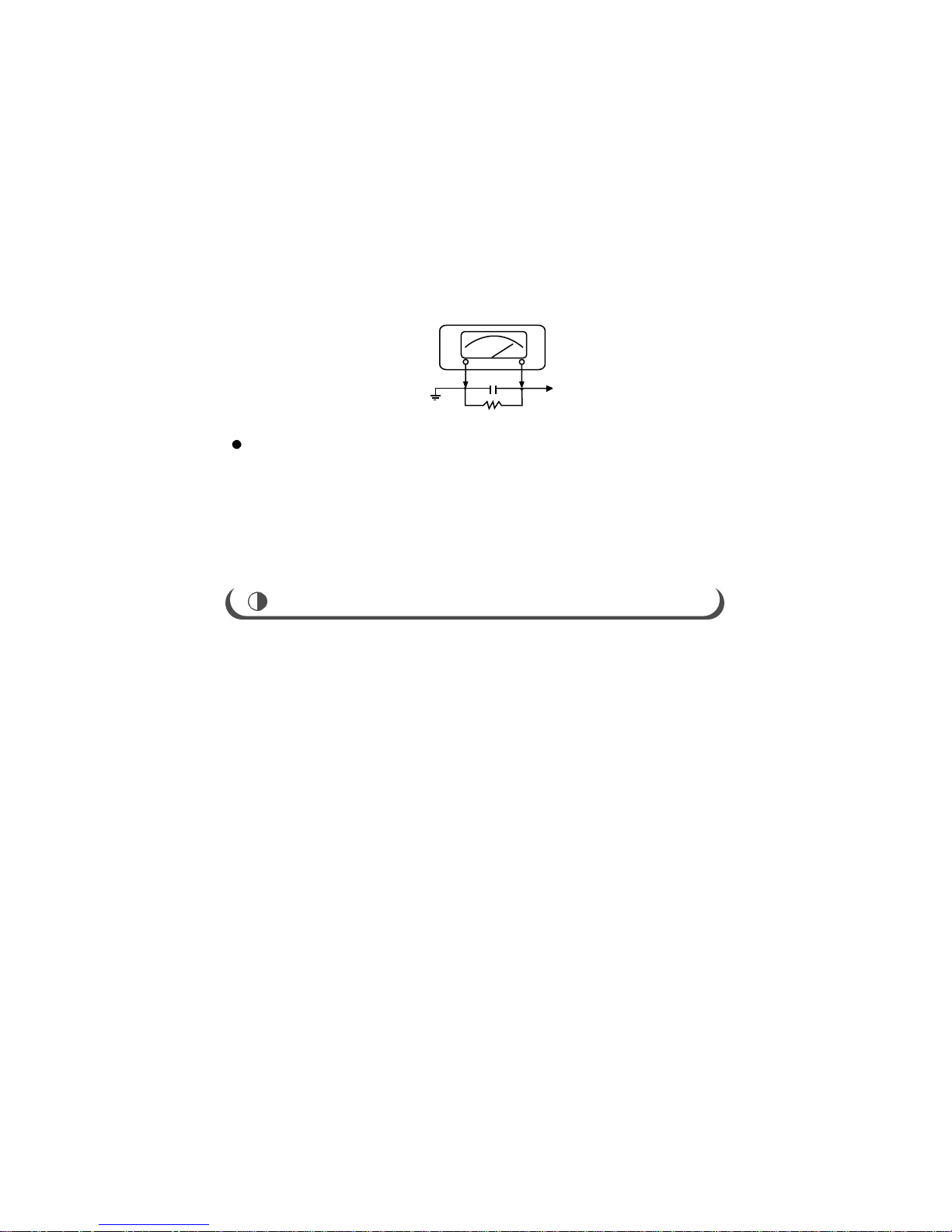
Measure the AC voltage across the combination of 1,500 ohm resistor and 0.15uF capacitor.
Reverse the AC plug at the AC outlet and repeat. AC voltage measurements for each
exposed metallic part.
Voltage measured must not exceed 0.75 volts RMS. This corresponds to 0.5 milliamp AC.
Any value exceeding this limit constitutes a potential shock hazard and must be corrected
immediately.
PRODUCT SAFETY NOTICE
Many electrical parts in this chassis have special safety-related characteristics. These
characteristics are often passed unnoticed by a visual inspection and the protection afforded by
them cannot necessarily be obtained by using replacement, rated for higher voltage, wattage,
etc. Replacement parts which have these special safety characteristics are identified in this
manual and its parts list. Before replacing any of these components, read the parts list in this
manual carefully. The use of substitute replacement parts which do not have the same safety
characteristics as specified in the parts list may create shock, fire, x-ray radiation or other
hazards.
1. In the majority of cases, a color television receiver will need only slight touch-up adjustment
upon installation.
Check the basic characteristics such as height, vertical sync, horizontal sync and focus.
Observe the picture for good black and white objectionable color shading. If color shading is
evident, demagnetize the receiver. If color shading still persists, perform purity and
convergence adjustments.
This should be all that is necessary for optimum receiver performance.
2. THIS RECEIVER TRANSISTORIZED AND SPECIAL CARE MUST BE TAKEN. READ THE
FOLLOWING NOTES BEFORE ATTEMPTING ALIGNMENT.
1) Alignment requires an exacting procedure and should be undertaken only when necessary.
2) An isolation transformer must be used to prevent a shock hazard.
3) The test equipment specified or its equivalent is required to perform the alignment properly.
Any use of equipment which does not meet these requirements may result in an improper
alignment.
4) A correct matching of the equipment is essential. A failure to use proper matching will result
in responses which cannot represent the true operation of the receiver.
5) An use of excessive signal from a sweep generator can cause overloading of receiver circuit.
It should be avoided to obtain a true response curve. Insertion of markers from the maker
generator should not cause distortion of the responses.
6) Connect the TV only to an AC power source with voltage and frequency as specified on the
backcover nameplate.
7) Do not attempt to connect or disconnect any wire while the receiver is in operation. Make sure
the power cord is disconnected before replacing any part in the receiver.
AC VOLTMETER
0.15uF
Place this probe
on each exposed
metal part
Good earth ground
such as a water
pipe, conduit etc
1500 ohm
10 watt
DIRECTION FOR GENERAL USE

AUTOMATIC DEGAUSSING
A degaussing coil is mounted around the picture tube so that external degaussing after moving
the TV should be unnecessary. But the receiver must be properly degaussed upon installation.
The degaussing coil operates for about 1 second after the power is switched ON. If the set is
moved or turned in a different direction, the power should be OFF for at least 15 minutes.
If the chassis or parts of the cabinet become magnetized, it will result in a poor color purity. If
this happens, use an external degaussing coil. Slowly move the degaussing coil around the
faceplate of the picture tube and the sides and front of the receiver. Slowly withdraw the coil to
a distance of about 6 feet before turning power OFF.
If color shading persists, perform the following Color Purity and Convergence adjustments.
HIGH VOLTAGE CHECK
CAUTION : There is no high voltage adjustment on this chassis. The +B power supply should
be +9 volts (with full color-bar input and normal picture level).
1. Connect an accurate high voltage meter to the second anode of the picture tube.
2. Turn on the receiver. Set bright and contrast controls to the minimum (zero beam current).
3. The high voltage must be measured below 29KV under any conditions.
4. Set sub-Bright DATA(SBR) minimum in FACTORY 1 MODE to ensure that the high voltage
does not exceed the limit under any conditions.
Purity Adjustment
1. Warm up the receiver for at least 30 minutes.
2. Plug in the CRT deflection yoke. Tighten the clamp screw.
3. Plug the convergence yoke into the CRT and set it as shown in Fig. B-1.
4. Input a black and white signal.
5. Fully demagnetize the receiver by using an external degaussing coil.
6. Turn the CONTRAST and BRIGHTNESS controls to maximum.
7. Loosen the clamp screw holding the yoke. Slide the yoke backward or forward to produce a
vertical green belt. (Fig. B-2)
8. Tighten the convergence yoke.
9. Slowly move the deflection yoke forward. Adjust for the best overall green screen.
10. Temporarily tighten the deflection yoke.
11. Produce blue and red rasters by adjusting the-low-light controls.
Check for good purity in each field.
12. Tighten the deflection yoke.
Center Convergence Adjustment
1. Warm up the receiver for at least 30 minutes.
2. Adjust the two tabs of the 4-pole magnets Change the angle between them.
Superimpose the red and blue vertical lines in the center area of the screen.
3. Adjust the BRIGHTNESS and CONTRAST controls for a well-defined picture.
4. Adjust the two tabs of the 4-pole magnets, and change the angle between them.
Superimpose the red and the blue vertical lines in the center area of the screen.
5. Turn both tabs at the same time, keeping the angle constant, and superimpose the red and
blue horizontal lines in the center of the screen.
6. Adjust two-tabs of 6-pole magnets to superimpose the red and blue lines onto the green.
Adjusting the angle affects the vertical lines, and rotating both magnets affects the
horizontal
lines.
7. Repeat adjustments 2-6, if necessary.
8. Since the 4-pole and 6-pole magnets interact, the dot movement is complex(fig B-3).
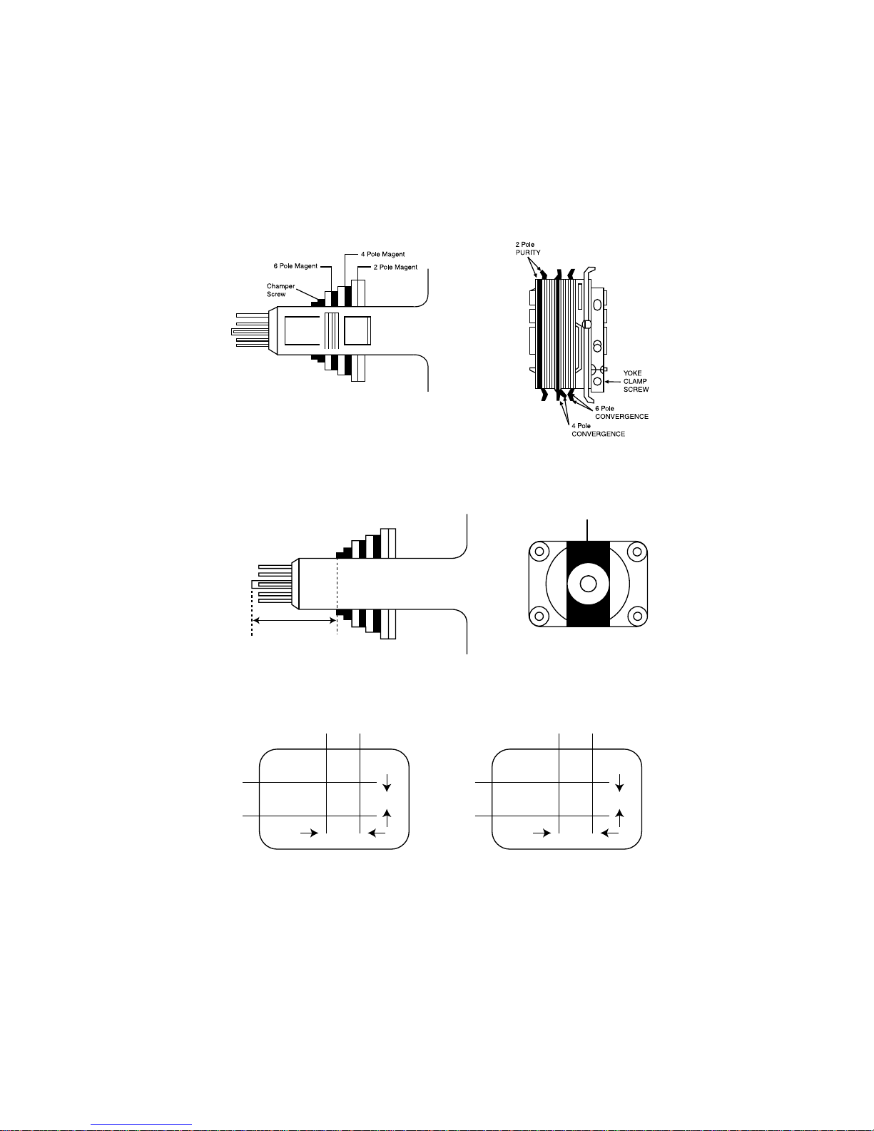
FIG. B-1 CONVERGENCE MAGNET ASSEMBLY
FIG. B-3 CENTER CONVERGENCE ADJUSTMENT
FIG. B-2 CENTER CONVERGENCE ADJUSTMENT
Vertical Green Belt
ADJUST
BLUE
BLUE
BLUERED RED
RED
BLUE/RED
GREEN
4-POLE MAGINETS MOVEMENT 6-POLE MAGINETS MOVEMENT
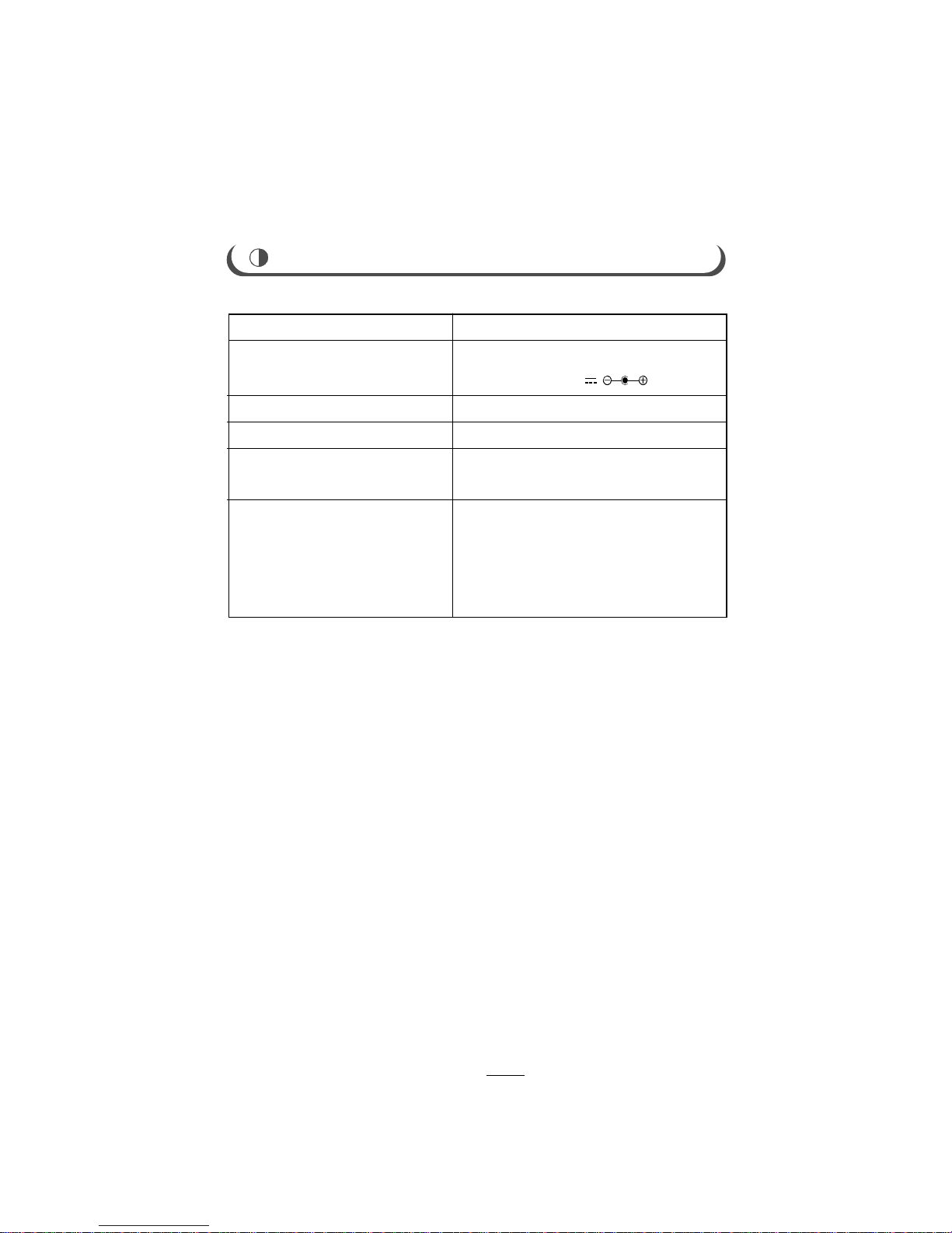
SPECIFICATIONS
RECEPTION SYSTEM
POWER SOURCE
SOUND OUTPUT POWER
ANTENNA IMPEDANCE
OPERATING FREQUENCIES
RECEIVING CHANNELS
PAL SECAM BG/DK I L & NTSC Playback
AC 90-250V~ 50/60Hz, 45W
DC 12-24V , 40W
1.0W
75 OHM UNBALANCED TYPE
VIDEO IF 38.9MHz
SOUND IF 33.4MHz
VHF
L
CH : 2 TO 4
VHF
H
CH : 5 TO 12
UHF CH : 21 TO 69
Hyper Band : S1 to S41
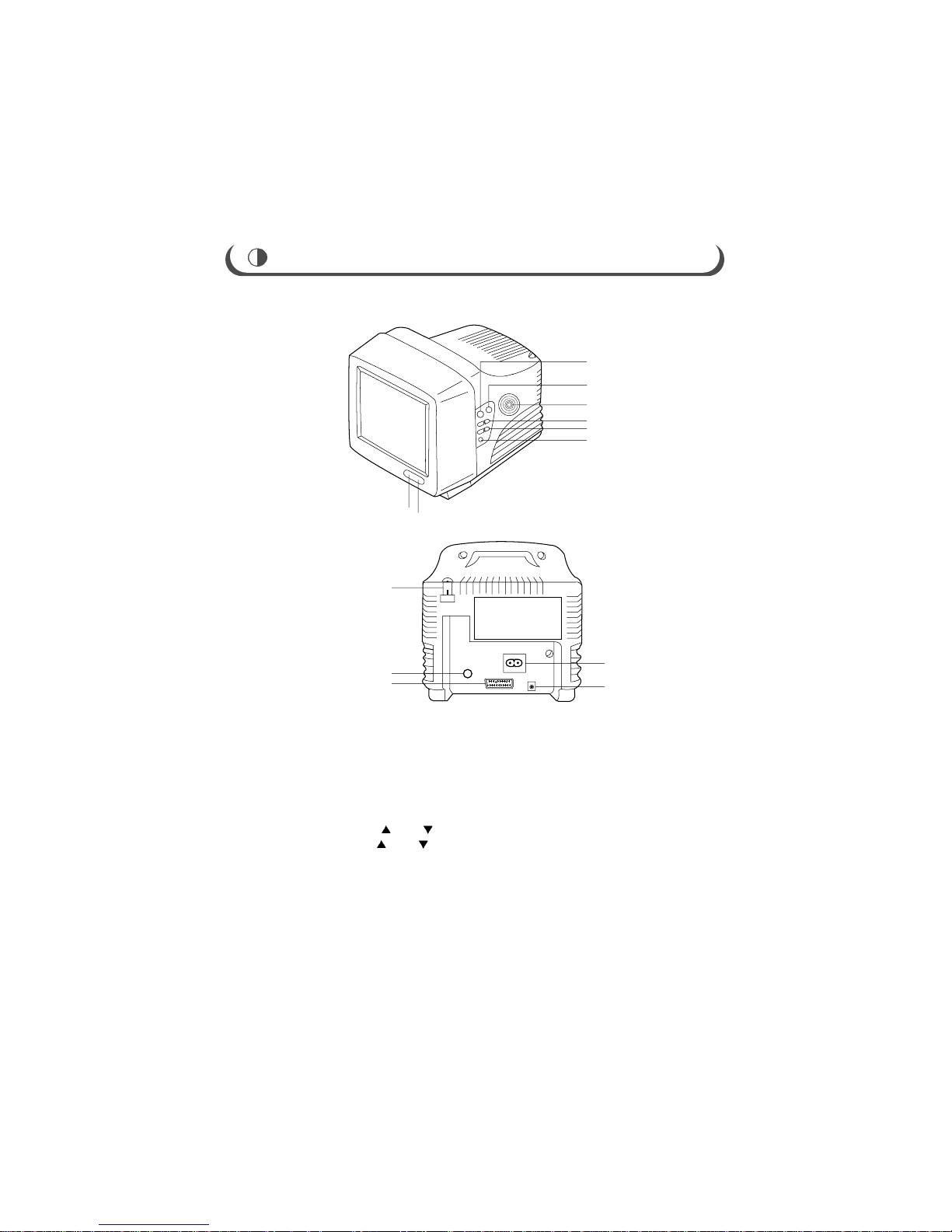
LOCATION OF CONTROLS
12
1
BACK
2
3
4
5
6
7
9
10
8
13
1. STAND-BY LAMP
2. Remote Control Sensor
3. Power Switch
4. TV/VIDEO Key
5. Speaker
6. Program Up (
)Down( )Key
7. Volume Up ( )Down( )Key
8. Earphone Jack
9. Antenna Holder
10. Antenna Jack(75 ohm)
11. Scart Jacks
12. AC Input Jack(Mains Power Socket)
13. DC Power Jack
11
FRONT
REMOTE CONTROL USE
BATTERY INSTALLATION
Replace two batteries in the battery compartment at the same time.
lnsert "AAA" batteries, observing the polarity ( or ) marked on the unit.
Batteries should last about a year under normal use. lf the operation is unstable(either channel or volume
does not change), replace the batteries. When the hand unit is not used for a long, or when the batteries are
used up, take out the batteries to prevent possible leakage. To avoid any malfunction of the remote control,
press only one button at a time.
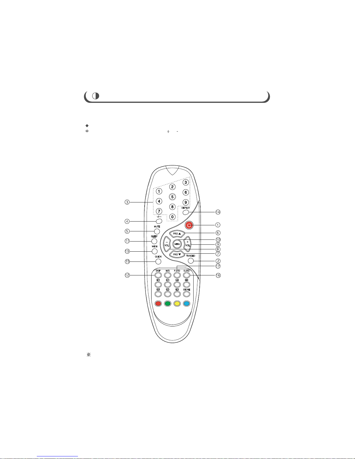
Remocon depends on the option of model

1. Power button
At Stand-by mode, the LED stand-by indicator is in RED color.
By pressing the power button, the TV will be turned ON, and the LED stand-by indicator will
be turned OFF.
2. TV/Video button
Select either TV or VIDEO mode.
3. 10 digit keys
It is used to directry select desired channel program number.
4. Two digit keys
1) -/-- key selects one-digit(0 to 9) or two-digit program number (10 to 99).
2) (-) or (--) is displayed by turns on the upper right position if you press this key repeatedly.
3) You can choose one-digit program number if (-) is shown and two-digit program number if
(--) shown.
ex1) Press 7 if you’d like to watch program number 7.
ex2) Press -/-- 1 7 if you’d like to watch program number 17.
If you want to watch program number 7 while (--) is already on, press -/-- 7 or 0 7.
5. Mute button
Switch the sound output either ON or OFF.
6,7. Program up( )/down( ) button
1) It is used to select the channel you want to watch on either upward or downward direction.
2) It makes the cursor to move while in main MENU, DVD MENU.
8,9. Volume up(+)/down(-) button
1) It adjusts the volume level of sound.
2) It is used to choose a specified mode in the main MENU by pressing VOL(+) button.
3) It controls the increase or decrease of each mode you selected.
4) It makes the cursor to move while in DVD MENU.
BASIC REMOTE CONTROL OPERATION
10. Menu button
It displays all the functions that user can control.
11. Sleep button
The television is automatically turned off after an elapse of the set sleep time.
1) The set time ranges from 10 to 180 minutes, which is repeated in sequence each time you press.
2) If you'd like to check the remaining SLEEP TIME after OSD disappears, press DISPLAY button.
12. Skip button
1) It can be used so that the unnecessary program number may not be displayed.
2) If you press this at a specific program number, OSD color of the current program number will
change from green to magenta.
3) If you want to watch the skipped program number, use 10 digit key to view it, then press SKIP
button, or operate AUTO PROGRAM in set up.
13. Wide button
This function lets you select one between wide and normal screen.
Wide ON 16 : 9 screen
Wide OFF 4 : 3 screen
14. Display button
Displays the current channel number, picture and sound state, sleep and clock.
15. Quick view button
Switches the current channel to the previously viewed channel.
16. Sound standard button
By pressing this, the sound output becomes 30 level.
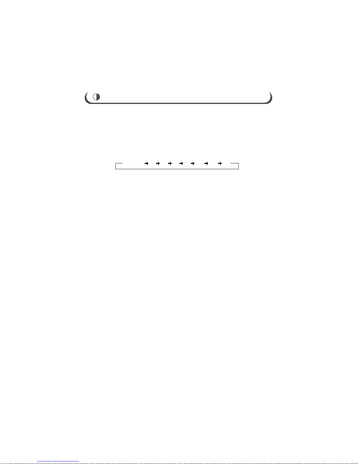
BASIC REMOTE CONTROL OPERATION
SLEEP OFF 10 30 60 90 120 150 180
GENERAL FEATURES AND ADJUSTMENTS
1. NOTE
Because this is not a hot chassis, it is not necessary to use an isolation transfromer.
However, the use of isolation transformer will help protect test instrunents.
Adjustment must be done in the correct order.
Supply
AC 90-250V~ 50/60Hz, 45W, DC 12-24V , 40W
in general.
Most of this chassis is designed to operate in the wide range of power supply.
Automatic degaussing
The degaussing circuit operates for about 1 secord after the power is switched on.
If you change the direction of the TV set in a state of Power-On, any color-blur may happen.
In that case, plug it off and plug it on after 1 more hour.
If color shading still persists, perform purity and convergence adjustments.
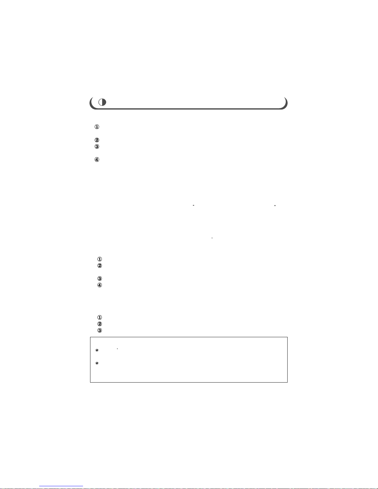
2. EEPROM(IC01) REPLACEMENT
When IC01 is replaced, all values are reset to INITAL MICRO-CONTROLLER DATA.
Because the pre-set data is reset after the replacement, above all, select factory
mode and write down all the pre-set data befote the replacement.
After the replacement, select factory mode and set the initial data referring to the
written-down data.
If you fogot to write down all the pre-set data or you can t turn on TV, re-adjust the initial
data according to the adjustment manual, follow the below procedure.
Replace the defective IC01 with a new one.
In the ON mode, Press DISPLAY + 1 + 1 + TV/VIDEO button
on the romote controller in sequence.
And then, factory mode will be displayed on the screen.
Input the signal like a color-bar pattern into antenna terminal, or input the current
broadcasting signal into antenna terminal.
3. WHEN CRT IS REPLACED
Do the following adjustments in the factory made.
SCREEN adjustment(SCREEN VOLTAGE)
W.BAL adjustment (R-Cut, G-Cut, R-DRV, G-DRV, B-DRV)
PICTURE adjustment (HRS(50), HRS(60), HEIGHT)
NOTE
You don t need to select 8.EEPROM Rest and 9.UOC Control.
Two items are critical to the system operation.
Press TV/VIDEO or MTS button when you want to finish the factory adjustments.
TV/VIDEO button:the early state that you bought TV sets.
MTS button:the previous state before you enter the factory mode.
1. Procedure for the factory adjustment mode
In the ON mode, the factory(Service) mode is activated by pressing the
DISPLAY + 1 + 1 + TV/Video button in sequence on the remote controller.
The menu of the factory mode will be displayed.
The factory mode consists of 9 componets:
1. SCREEN
2. W.BAL
3. PICTURE
4. SERVICE1 ;You do not need to Select it.
5. VOLUME TEST ;You do not need to Select it.
6. DEVICE CHECK ;You do not need to Select it.
7. OPTION
8. EEPROM RESET ;You do not neet to Select it
9. UOC CONTROL ;You do not need to Select it.
10. V-CHIP TEST ;You do not need to Select it.
Select each adjustment mode by pressing CH up( )or CH down( ) button.
And access it by pressing vol up(+)or vol down(-) button.
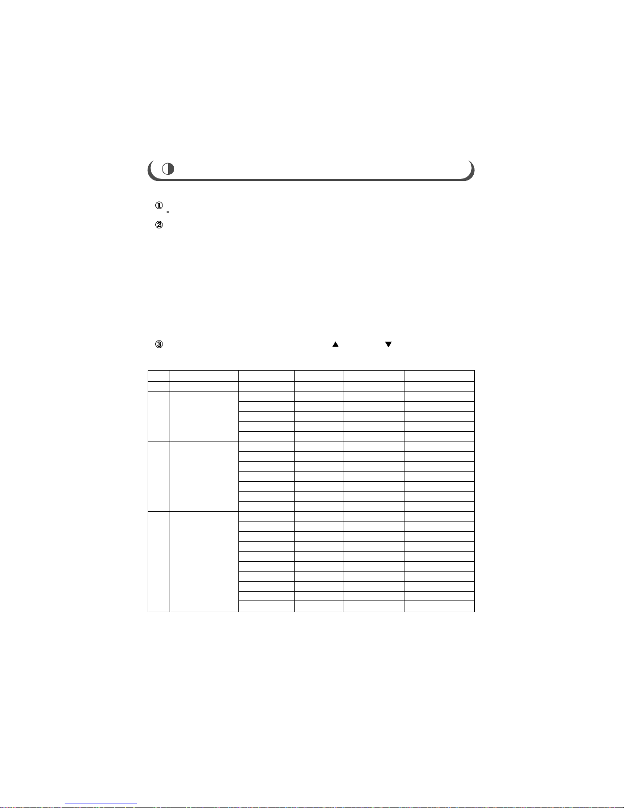
FACTORY/SERVICE ADJUSTMENTS
NO
1
2
3
4
PART
SCREEN
W.BAL
(WHITE BALANCE)
WHITE
PICTURE
SERVICE 1
OSD
R-CUT
G-CUT
R-DRV
G-DRV
B-DRV
HRS(50)
HRS(60)
VRS
HEIGHT
V-SLOPE
S-C
W-HEIGHT
TEXT
NTSC
LANGUAGE
AUTO P.OFF
SECAM L
RANGE
0~63
0~63
0~63
0~63
0~63
0~63
0~63
0~63
0~63
0~63
0~63
0~63
ARABIC/ENG
FARSI/ENG
WEST EURO
CYL/ENG
EAST EURO
ON/OFF
WITH ARABIC
W/O ARABIC
ON/OFF
ON/OFF
INITIAL DATA
32
32
32
32
32
40
48
24
17
32
24
6
OFF
W/O ARABIC
ON
ON
COMMENT
NTSC M/PAL M
OSD
CONTRAST
BRIGHT
COLOR
SHARPNESS
TINT
AGC
UOC
EEPROM
MSP34XX
TUNER
SDA9489X
TDA9859
ETC 00002
ETC 00003
RANGE
0~63
0~63
0~63
0~63
0~63
0~63
MIN / MAX
INITIAL DATA
0 35 55
0 30 50
0 28 63
0 24 48
0 32 63
33
MIN
Connected
Connected
Disconnected
Connected
Disconnected
Disconnected
Disconnected
Disconnected
COMMENT
Min Cnt Max
Don’t select it
Don’t select it
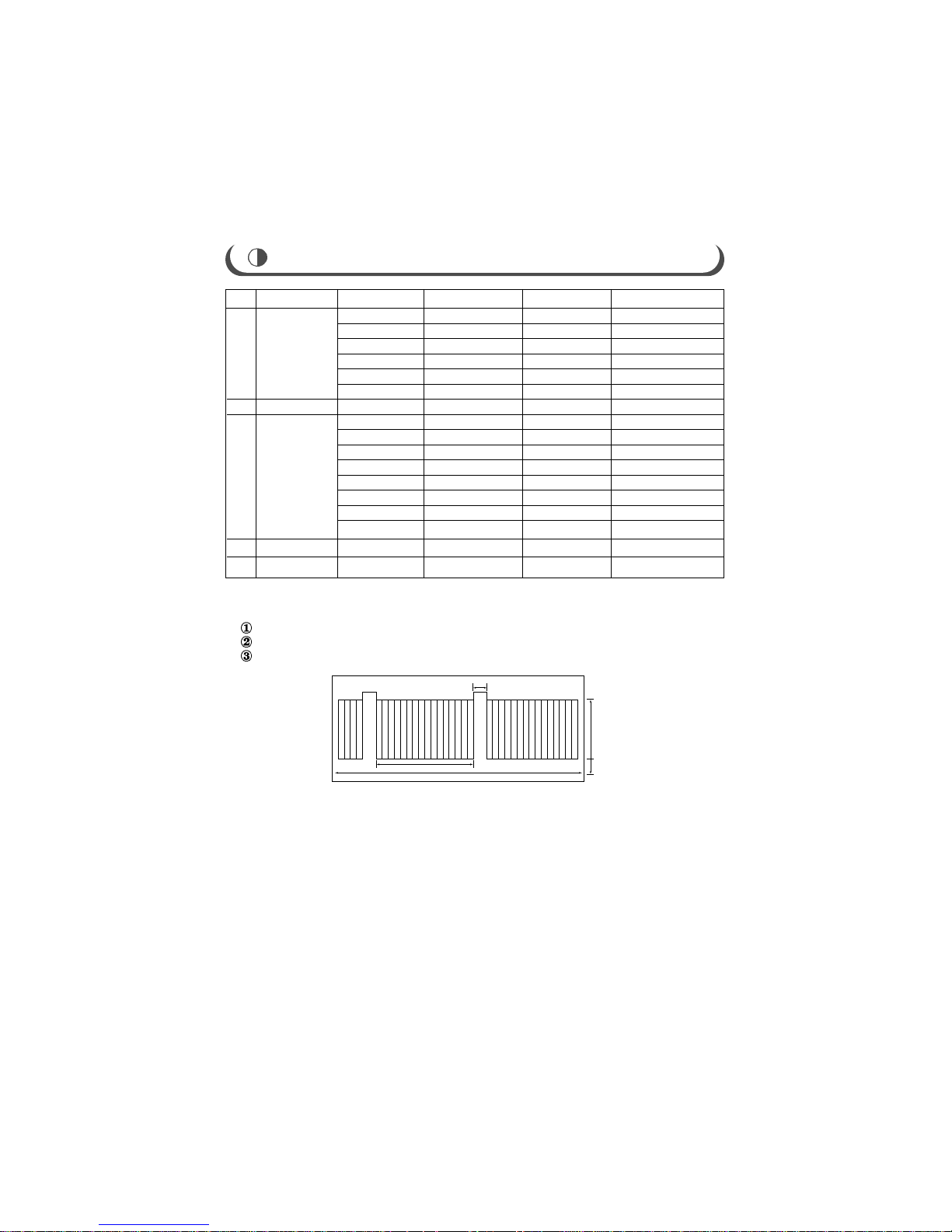
2. SCREEN Voltage Adjustment
Turn the TV set to receive a color bar pattern.(Standard picture)
Connect the probe of oscilloscope to the RK (Red Cathode) of CPT Board.
Adjust Screen Volume of FBT so that the waveform is the same as below figure.
FACTORY/SERVICE ADJUSTMENTS
1H-LINE
Horizontal
FlyBack Time
Black level
145Vp-p
White level
GND for dc
The waveform of RK(Red Cathode) of CPT Board
NO
5
6
7
8
9
PART
SERVICE 2
VOLUME TEST
Device Check
EEPOM Reset
UOC Control
3. Deflection Adjustments
HRS(50) adjustment : Tune the TV set to a LION HEAD pattern signal with 50Hz of
vertical frequency.
HRS(60) adjustment : Tune the TV set to a LION HEAD pattern
Signal with 60Hz of vertical ferquency.
HEIGHT adjustment : Tune the TV set to a LION HEAD pattern
Signal and adjust the vertical amplitude to
4 bars both the Top and the bottom.
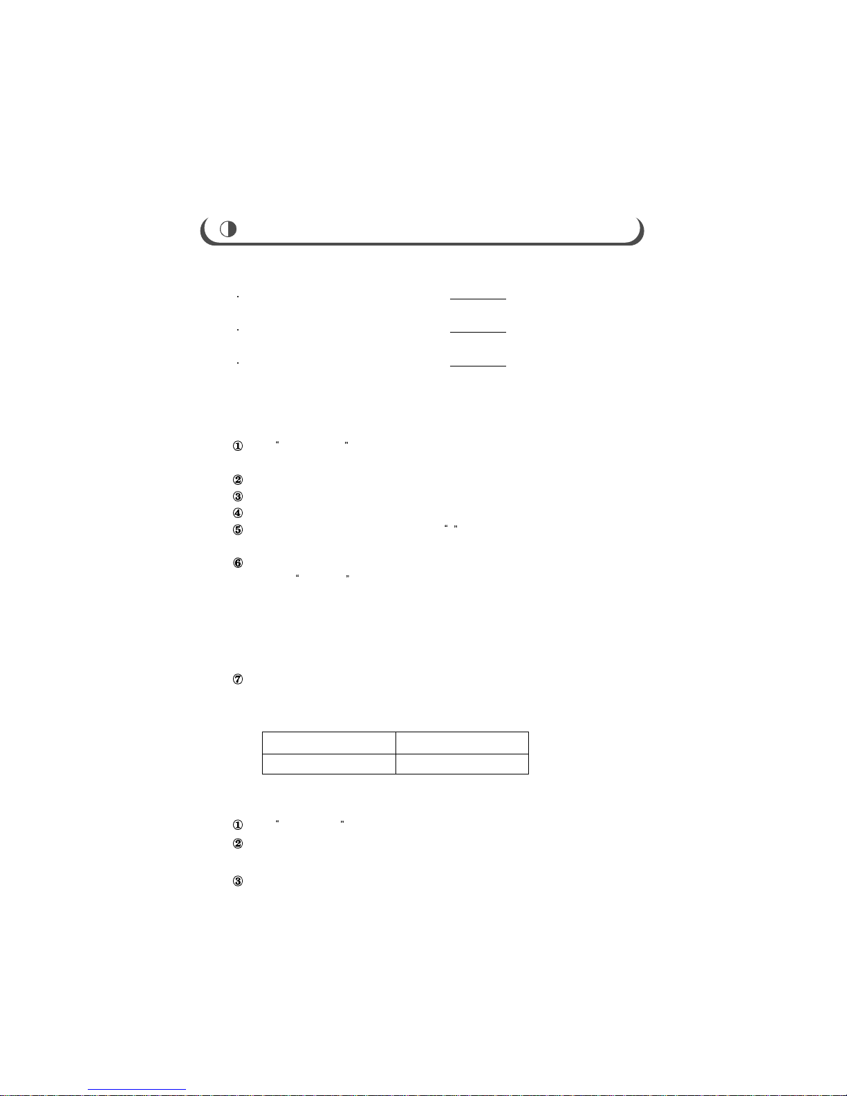
4. WHITE BALANCE Adjustments(manual)
Input PURE WHITE pattern into antenna terminal or into
Video input terminal.
Keep TV on for about 30 minutes prior to white balance adjustment.
Screen Voltage Adjustment (page 14)
Place the probe of CRT Analyzer at the center Position of picture screen.
Adjust CONTRAST & BRIGHTNESS until Y value of CRT analyzer
becomes 35FL above roughly.
Select 2.W.BAL and press Vol(+) button.
And then R-CUT 32 will be displayed.
1 button : R-CUT
5 button : G-CUT
9 button : R-DRV
0 button : G-DRV
-/-- button : B-DRV
Select R-DRV & G-DRV and adjust them to get the
color coordinates below in the high light state.
In this case, fix the reference color(B-DRV) as possible as.
5. Focus ADJUSTMENT
Input CROSS DOT pattern into antenna terminal on video input terminal.
Rotate the variable resistor of FOCUS terminal on the flyback
transformer until the horizontal and vertical line becomes slim.
Check the surrounding FOCUS in the lion head pattern.
X COORDINATE Y COORDINATE
0.261 0.268
FACTORY/SERVICE ADJUSTMENTS
 Loading...