

Page 1

This file was downloaded and provided FREE OF CHARGE
from the ManualDirectory community.
You can find many free to download Service Manuals & Schematics at
http://www.manualdirectory.co.uk
Page 2
R
- CTV-1010XKTL
- CTV-1010XKTL
CTV-1010XKTL
Service Manual
Service Manual
Page 3

Page 4
4. Alignment and Adjustments
4-1 Preadjustment
4-1-1 Factory Mode
1. Do not attempt these adjustments in the VIDEO mode.
2. The Factory Mode adjustments afe necessary when either the EEPROM(QO02) or the CPT
is replaced.
3. Do not tamper with the "Adjustment" screen of the Factory Mode menu. The screen is intended
only for factory use.
4-1-2 When EEPROM (0002) is replaced
1. When QO02 is replaced ali adjustment data revert to their initial values. It is necessary to reprogram this data.
2. After QO02 is replaced, warm up the TV for 10 seconds.
4-1-3 When CPT is replaced
1. Make the following the adjustments after setting up purity and convergence:
White Balance
Vertical center
Vertical size
Horizontal size
4-2 Factory I Servi ce Mode
4-2-1 Procedure for the "Adjustment" Mode
1. This mode uses the standard remote control. The Factory (Service) Mode is activated by
pressing the"Factory"key on the remote control.
2. The Factory Mode will be displayed. The Factory Mode has six components :
VCO ADJ, SCR ADJ, HRS, HEIGHT, W. Bal, AGC Auto.
3. Access the Adjustment Mode by pressing the VOLUME keys (Up or Down). The adjustment
Parameters adjusted afe listed in the accompanying table, and they afe selected by pressing
the PROGRAM keys (Up or Down).
4. The VOLUME keys increase or decrease the adjustment values.
;
-~
Page 5
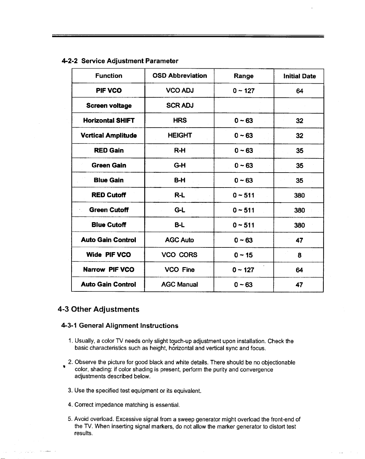
4-2-2 Servi ce Adjustment Parameter .
Function OSD Abbreviation Range Initial Date
PIF VCO VCO ADJ O -127 64
Screen voltage SCR ADJ
Horizontal SHIFT HRS O -63 32
Vcrtical Amplitude HEIGHT O -63 32
REO Gain R-H O -63 35
Green Gain G-H O -63 35
Blue Gain B-H O -63 35
REO Cutoff R-L 0-511 380
Green Cutoff G-L O -511 380
Blue Cutoff B-L 0-511 380
Auto Gain Contrai AGC Auto O -63 47
Wide PIF VCO VCO CORS O -15 8
Narrow PIF VCO VCO Fine O -127 64
Auto Gain Contrai AGC Manual 0-63 47
4-3 Other Adjustments
4-3-1 Generai Alignment Instructions
1. Usually, a colar TV needs only slight to.uch-up adjustment upon installation. Check the
basic characteristics such as height. horizontal and vertical sync and focus.
2. Observe the picture far good black and white details. There should be no objectionable
.colar, shading: if colar shading is present, perform the purity and convergence
adjustments described below.
3. Use the specified test equipment or its equivalent.
4. Correct impedance matching is essential.
5. Avoid overload. Excessive signal from a sweep generator might overload the front-end of
the TV. When inserting signal markers. do not allow the marker generator to distort test
results.
Page 6
6. Connect the TV only to an AC power source with voltage and frequency as specified on the I
back cover nameplate.
7. Do not attempt to connect or disconnect any wires while the TV is turned on. Make sure that
the power cord is disconnected before replacing any parts.
8. To protect against shock hazard, use an isolation transformer.
4-3-2 Automatic Degaussing
A degaussing coil is mounted around the picture tube, so that external degaussing after
moving the TV should be unnecessary. 8ut the receiver must be properly degaussed upon
installation .
The degaussing coil operates far about 1 second after the power is switched ON. If the set is
moved or turned in a different direction, the power should be OFF far at least 10 minutes.
If the chassis or parts of the cabinet become magnetized, poor colar purity will result. If this
happens, use an external degaussing coil. Slowly move the degaussing coil around the
faceplate of the picture tube and the sides and front of the receiver. Slowly withdraw the coil to
a distance of about 6 feet before turning power OFF.
If colar shading persists, perform the following Colar Purity and Convergence adjustments.
4-3-3 High Voltage Check
CAUTION : There is no high voltage adjustment chassis. The 8+ power supply should be
+8.5 volts (see table 1).
1. Connect a digital voltrneter to the second anode of the picture tube.
2. Turn on the TV. Set the 8rightness and Contrast controls to minimum (zero beam current).
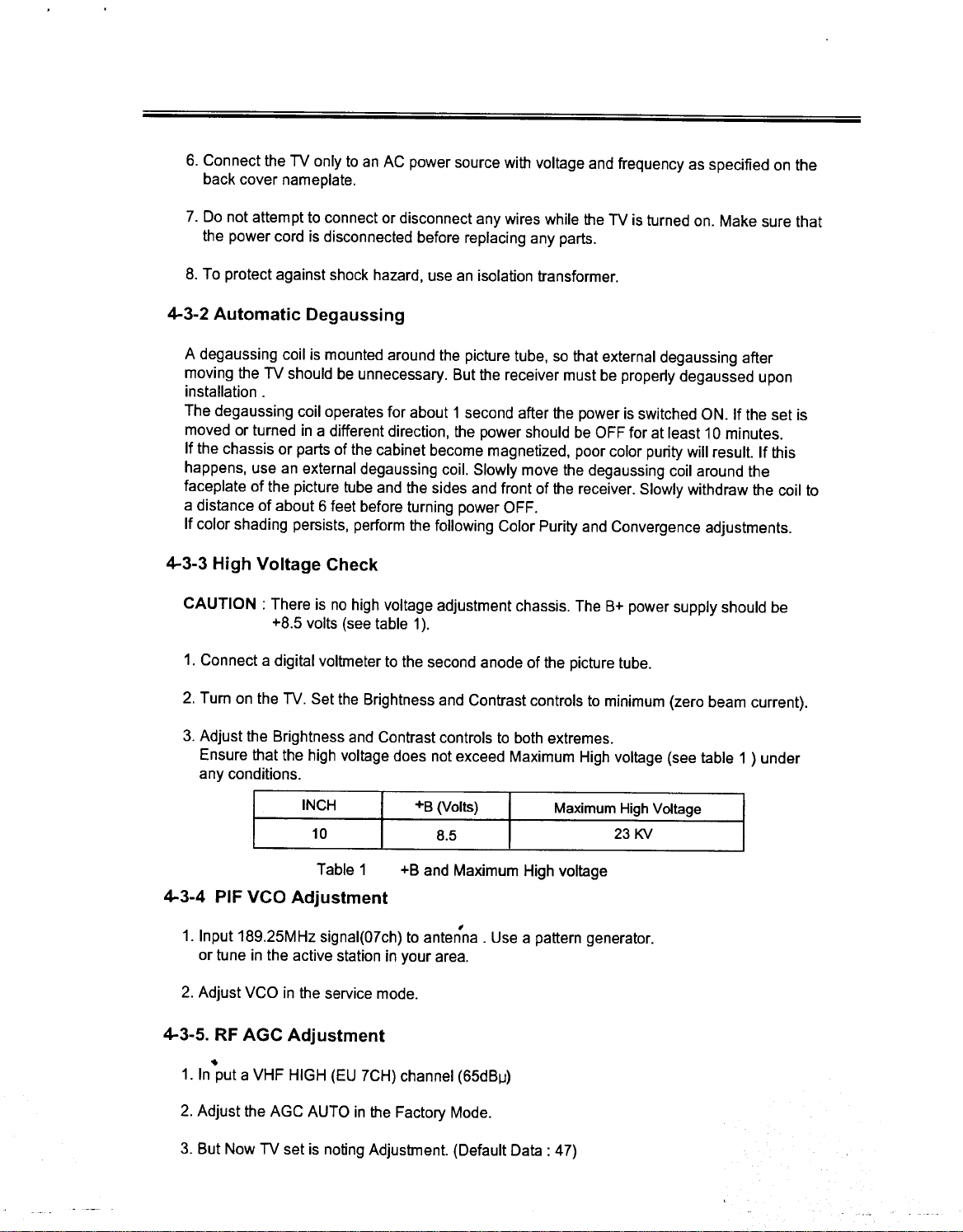
3. Adjust the 8rightness and Contrast controls to both extremes.
Ensure that the high voltage does not exceed Maximum High voltage (see table 1 ) under
any conditions.
INCH +8 (Volts) Maximum High Voltage
10 8.5 23 KV
Table 1 +8 and Maximum High voltage
4-3-4 PIF VCO Adjustment
1. Input 189.25MHz signal(O7ch) to antenna. Use a pattern generator.
or tune in the active station in your area.
2. Adjust VCO in the service mode.
,
4-3-5. RF AGC Adjustment
.
1. In put a VHF HIGH (EU 7CH) channel (65d81J)
2. Adjust the AGC AUTO in the Factory Mode.
3. 8ut Now TV set is noting Adjustrnent. (Default Data: 47)
Page 7
4-3-6 Screen Adjustment
1. Tune to the ACTIVE channel.
2. Adjust the FACTORY key is pressed on Remote Controller, Factory Mode shows up.
3. Selected OSO colar is red.
4. When the VOL + keyis pressed, the screen turns to one horizontalline.
5. Adjust SCREEN VR of FBT to make 1 dot bar.
6. After adjustment, once VOL + key is pressed again, it turns to FACTORY Mode.
4-3-7 WHITE BALANCE ADJUSTMENT (MANUAL)
1. Tune the monochrome (Lion head pattern) channel and warm up the set far 20 minutes.
2. Select the FACTORY MODE. THE FACTORY (Service) MODE is activated by pressing the
"FACTORY" button on the remote contrai.
3. On Factory mode, select number 5.
4. By using PROGRAM UP/DOWN button, select "WB ADJ".
5. Press the VOL + button to make horizontalline.
6. Adjust the VR Screen far a 1 dot line.
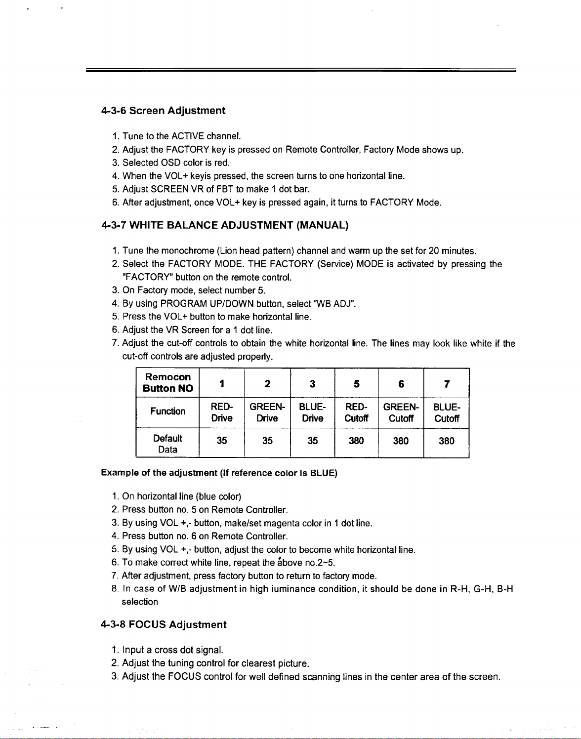
7. Adjust the cut-off controls to obtain the white horizontalline. The lines may look like white if the
cut-off controls are adjusted properly.
Remocon
Button NO 1 2 3 5 6 7
F ti RED- GREEN- BLUE- RED- GREEN- BLUE-
unc on
Default 35 35 35 380 380 380
Data
Example of the adjustment (If reference colar is BLUE)
1. On horizontalline (blue colar)
2. Press button no. 5 on Remote Controller.
3. By using VOL +,- button, make/set magenta colar in 1 dot line.
4. Press button no. 6 on Remote Controller.
5. By using VOL +,- button, adjust the colar to become white horizontalline.
6. To make correct white line, repeat the above no.2-5.
7. After adjustment, press factory button to return to factory mode.
8. In case of W/B adjustment in high iuminance condition, it should be done in R-H, G-H, B-H
selection
D . D .
D .
C ff Cnve nve nve ufo utoff Cutoff
4-3-8 FOCUS Adjustment
1. Input a cross dot signal.
2. Adjust the tuning contrai far clearest picture.
3. Adjust the FOCUS contrai far well defined scanning lines in the center area of the screen.
Page 8
I
-
4-3-9 Purity Adjustment
1. Warm up the receiver far at least 30 minutes.
2. Plug in the CRT deflection yoke. Tighten the clamp screw.
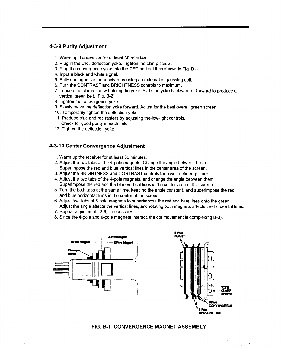
3. Plug the convergence yoke into the CRT and set it as shown in Fig. B-1.
4. Input a black and white signal.
5. Fully demagnetize the receiver by using an external degaussing coil.
6. Turn the CONTRAST and BRIGHTNESS controls to maximum.
7. Loosen the clamp screw holding the yoke. Slide the yoke backward or forward to produce a
vertical green belt. (Fig. B-2)
8. Tighten the convergence yoke.
9. Slowly move the deflection yoke forward. Adjust far the best overall green screen.
10. T emporarily tighten the deflection yoke.
11. Produce blue and red rasters by adjusting the-low-light controls.
Check far good purity in each field.
12. Tighten the deflection yoke.
4-3-10 Center Convergence Adjustment
1. Warm up the receiver far at least 30 minutes.
2. Adjust the two tabs of the 4-pole magnets: Change the angle between them.
Superimpose the red and blue verticallines in the center area of the screen.
3. Adjust the BRIGHTNESS and CONTRAST controls far a well-defined picture.
4. Adjust the two tabs of the 4-pole magnets, and change the angle between them.
Superimpose the red and the blue verticallines in the center area of the screen.
5. Turn the both tabs at the same time, keeping the angle constant, and superimpose the red
and blue horizontallines in the center of thescreen.
6. Adjust two-tabs of 6-pole magnets to superimpose the red and blue lines onta the green.
Adjust the angle affects the verticallines, and rotating both magnets affects the horizontallines.
7. Repeat adjustrnents 2-6, if necessary.
8. Since tlle 4-pole and 6-pole magnets interact, the dot movement is complex(fig B-3).
,
.~~
2 ,... :
"C~D tJ
----W~~~~D'- '--.
I .
.I
I i
i
i
i
)
, =~
".
~E)O'
FIG. B-1 CONVERGENCE MAGNET ASSEMBL Y
Page 9

DEFLECTION TOKE
A
CONVERGENCE
/ MAGNET ASS'Y RUBBER WEDGES
RUB
~WE
31mm(1-3/16")
ECTION TOKE
RUBBER WEDGES
LOCATION
FIG. B-2 COLaR PURITY ADJUSTMENT
6-POLE
MAGNET
ADJUST THE ANGLE
4M
PURITY (HORIZONTAL LlNES)
MAGNET
(VERTICAL LlNES)
ROTATE TWO TABS
ATTHE SAME TIME
ADHESIVE
BLU RED ~ GRN BGR
RED
RED GRN
RED .
~~ R
~BLU ~
t R
4-Pole Magnets Movement 6-Pole Magnets Movement Incline the Yoke up(or down) Incline the Yoke right(or lell)
Center Convergence by Convergence Magnets Circumference Convergence by DEF. Yoke
FIG. B-3 CONVERGENCE ADJUSTMENT
G
B
Page 10

4-3-11 Geometry Adjustment
1. Input a lion head or philips pattern.
2. Adjust VRS (R391) Volume to locate the picture in center of the TV screen.
3. Adjust V-HEIGHT(Height). Set the vertical size to "4-5".
4. Adjust H-PHASE(HRS). Align the center of the lion head or philips pattern with the center
of the TV screen.
5. Using Devices and Description.
5-1 Main Signal processar (STV 2246/8)
5-1-1 Feature
o IIC Bus Contrai.
o PIF circuit with Demodulation.
o SIF circuit with QSS Structure.
o Inter Carrier Capability.
o Built in Sound Bandpass.
o integrated chroma frlters and Luma Delay Line
o OSO RGB in puts
o External RGB in put
o PAL/NTSC/SECAM CHROMA Demodulators.
o Black stretch circuito
o Vertic~l.countdown.
o Two PLLs Horizontal Deflection.
;
Page 11

.I
STV223XD/3X14X -
5-1-2 Pinning and Deseription .
Pin N8
STV224X/8X Symbol Description
SDIP56
1 SIFIN1 SIF Input
2 SIFIN2 SIF Input
3 AGCSIFCAP AGC SIF Capacitor
4 REFI Voltage Reference Filtering
5 AGCPIFCAP AGC PIF Capacitor
6 PIFIN1 PIF Input
7 PIFIN2 PIF Input
8 TUNERAGCOUT AGC Tuner Output
9 IFPLL IF PLL Filter
10 GNO IF IF Ground
11 AM/FMOUT/SC AM/FM Mono Sound or Stereo Carriers Output
12 VcclF 5V IF Supply
13 INTCVBSOUT Internai CVBS Output
14 EXTAUDIOIN External Audio Input
15 PIFLC1 LC Input
16 PIFLC2 LC Input
17 Vcc2 Video/Luma Supply Volta e 8
18 CVBSIN1 Internai Video Input
19 GNO2 Video/Luma Ground
20 CVBSIN2 External Video Input
21 BS Black Stretch Capacitor
22 Y/CVBSIN3 Y(SVHS) or CVBS3 Externallnput
23 CHR Chroma (SVHS) Input
30 BOUT Blue Output
31 GOUT Green Output
32 ROUT Red Output
33 ICATH Cathode Current Measurement In ut
34 BOSO OSO Blue Input
35 GOSO OSO Green Input
36 ROSD OSO Red Input
37 FBOSO OSO Fast Blankin
38 XTAL3/BTUN ~ 3.5X MHz Crystal or Cicche Filter Tuning Capacitor
39 XT AL2 3.5X MHz Crystal
40 XT AL 1 4.43/3.5X MHz C stai
41 CLPF Chroma PLL Filter
42 X1NAMP/CHROUT XTAL 1 Contrai Pin, Vertical Amplitude DAC
Output and Chroma Reference Signal Output.
43 GND1 Chroma/Scanning Ground
~/16~
Page 12

STV223XD/3XJ4X -
Pin N° I
STV224X/8X Symbol Description
SDIP56
45 Vcc1 Chroma/Scanning Power Supply(8V)
46 BCUSAF Beam Current Umiter Control Voltage and
Safety Input(XRAY)
47 VERT Vertical Output Pulse
48 HOUT Horizontal Output Pulse
49 LFB/SSC Une Flyback Input and Super-sandcastle Output
50 SLPF Scanning PLL Filter
51 SCL 12C Bus Clock Input
52 SDA IlC Bus Data Input
53 VccD Digital SUPPIy Voltage(5V)
54 GND D Digital Ground
55 AUDIOOUT Main Audio Output
56 FMCAP FM Demodulation Capacitor
25 BEXT External Blue Input
26 GEXT External Green Input
27 REXT External Red Input
28 FBEXT External Fast Blankin In ut
24 APR Automatic RGB Peak R ulation
44 CVBSOUT2 Second Video Switch Output
~
~17~
Page 13

5-1-3 Block Diagram (STV2246) (SDIP56) I
c -<
",CC c'" t:; 1-1- I- t:;
g: ~~~[l5::1 '<555 ffi <5
-< u.a:~m~.2.a:~m > :r
u.
REXT LFB/SSC
GEXT
BEXT SLPF
FBEXT
BS XTAL2
CVBSOUT2
CVBSIN1
CVBSIN2
Y/CVBSIN3 ~
o FMOUT
c
~ o
u.~
~
CHR
X1NAMP/CHROUT
CLPF
XTAL1
XTAL3
FMCAP
INTCVBSOUT
IFPLL
PIFLC2
PIFLC1
~ ~ ~ t:; ~ ~ ~ ~ § ~ ~ !!,
u.u. () <5 >z~c z z
a: a: !!, () ,ft > Z ~ ~
a. ~ ~ ~
() -<
~ a:
-< w
~
I-
>8 C >9 ~
~1à\ MANUAL
EXTAUDIOIN
AUDIOOUT
v~
SCL
SDA
Page 14

Block Diagram (STV2248) (SDIP56) .
~ooo~ t:; 1-5 I- t:;
g: m'8'8~u 5550 ffi o
.., u.","mm_"",m > :IO
REXT LFB/SSC
GEXT
BEXT
FBEXT
BS XTALI
CVBSOUT2
SLPF
X1NAMP/CHROUT
CLPF
XTAL2
CVBSINI XTAL3iBTUN
CVBSIN2
Y/CVBSIN3
AM/FMOUT/SC
CHR
FMCAP
INTCVBSOUT
IFPLL
PIFLC2
PIFLCI
~
z a. B ~ '" a. § o u. u. G ~ " '"
Li:~ u Li: Li: u>~§o>z>z
il: a. ~ 8 Ci5 Ci5 !!. ,,> ~ " (!)
.., zz.., --00"0
u .., ~
(!) '" (!)
.., w ..,
z
EXTAUDIOIN
AUDIOOUT
v~
SCL
SDA
Page 15

.I
STV223XD/3X14X -
5-1-4 Functional Description frequency. The automatic calibration of the FM I
demodulator VCO is operating in ali sound
The STV2238D is an integrated device which standard independently tram chroma crystal VCO
performs the processing of PIF, SIF, Video, chroma, frequency, which can be either 4.4 MHz or 3.5
scanning far PAL, SECAM and NTSC standards. It MHz. For each sound carrier frequency, IC sends
includes a base band chroma delay line, Video, to the MCU an indication of the sound sub-carrier
SVHS and audio switches. level so that the MCU can select the proper
standard.
1 -DETAILED FEATURES demodulation VCO is calibrated. This information
1. 1 -Power Supplies .
VcclF: 5 V power supply dedlcated to IF processors.
VccDIG: 5 V power supply dedlcated to 12C bus and
digital parts. GND D is the ground reference -~ound demodulator output: either an.AM or FM
of these parts. slgnal can be the output far Mono chassls, or
Vcc1: 8 V power supply far video switches, scanning -Sound sub-carriers far Stereo chassis.
part and the chroma decoder. GND 1 is
the ground reference of ali these functions.
Vcc2: 8 V power supply far the luminance, RGB
processing parts and audio switch. GND2 is the -One SCART switch.
ground reference of these parts. -Bus controlled volume and mute.
.FM deviation I 25 or I 50 KHz).
.-AM demodulator.
-Sound sub-carrier level is valid when the FM
can be read through the 12C Bus.
-Bus controls far FM de-emphasls (50 or 75 JLS) and
1 4 A d. S .
t h.-U IO Wl c
-In case of STEREO chassis, AM sound can be
1. 2 -PIF selected on the main audio output.
-AGC amplifier.
-PLL synchronous demodulator. Bus controlled VCO
far integrated tuning of t~e ext~rna~ LC resonator -SA W filter switch contrai pin is available in the
far 38.9 MHz VCO, LC coli speclficatlon has to be: TQFP64 package. The SAW filter switch contrai pin
C=39pF, f=44 MHz I,2%(LC ~ot c~nnected) permits the selection of the proper SAW filter
far 33.9 MHz VCO(L), VCO 15 swltchable through characteristic (e.g.: M/N or BGDK characteristic
bus contrai. selection). In a multi standard chassis, two output
-Digital AFC through bus. voltages are selected through the 12C bus: low level
-IF AGC voltage at 0.4 V Max., and high level voltage at 4 V
Negative modulation: top sync regulation, regula- Min.
tion of overmodulated signals (overmodulation
regulation circuit enabled through bus contrai). "
Positive modulation: main regulation on white level 1.6 -Video Swltches
with black levellimitation. ,
-Tuner delayed AGC wlth bus contrai far AGC galn CVBS output which may be used to drive a teletext
and threshold. decoder.
1. 3 -SIF Capability to output recombined Y+C signal.
-QSS strutture. -SVHS switch, Y input is combined with CVBS 3
-Built in sound bandpass. input. CVBS/SVHS modes can be selected either
AGC SIF by bus contrai (software selection), or by sensing
-.DC voltage on Chroma input pin (hardware
-PLL FM demodulator far 4.5, 5.5, 6.0 or 6.5 MHz selection). If chroma input is connected to ground
carrier. Sound standard selection is controlled by then CVBS mode is selected and the bus contrai is
MCU. VCO of the FM demodulator is automatically not attive. If the chroma input DC level is higher
calibrated using chroma crystal VCO reference than the SVHS threshold, then the bus contrai is
..-Video switch with three CVBS inputs and one
1.5- SAW Filter Switch Control
-A second CVBS output in the TQFP64 package.
Ali switches are independently controlled.
Page 16

, I
STV223XD/3X14X ~
active and controls the SVHS switch. Thus, The first PLL is inhibited from li ne 309 to line 4.5 (or I
hardware selection of the SVHS mode using a 314) in 50 Hz mode and from line 258 to line
special SVHS connector including a mechanical 5.5 (or 264) in 60 Hz mode. The lime constant
switch is possible. In such an application, the bus values are chosen by means of external
contrai is set to SVHS mode, and the CVBS mode components.
is selected by connecting the chroma input pin to -Possibility to force through the bus the short lime
ground. constant during the ali frame.
-Possibility to force through the bus the long lime
constant during the ali frame.
2 -DEFLECTION PART -Possibility to force through the bus a very long lime
constant during the ali frame.
-Fully integrated sync. separator with a low pass ...,.
filter, black level alignment of the CVBS input, a VIdeo !dent~ficatl?~: In~ependent ~rom P.LL 1. .
slicing level at 50% of the synchronized puise The video Identlflcatlon status IS avallable In the
amplitude. output register of the 12C bus decoder.
-Vertical. output pulse locked on 2 FH frequency to Generation of burst gale pulses and line frequency
perfect Interlace. signals from the first PLL to drive the chroma and
-Auto calibrated VCO using the chroma crystal video circuits.The burst gale pulse is also sent to the
reference. The crystal contrai Pin X1CTL indicates super-sandcastle generator.
the crystal reference value on Pin XT AL 1.
When a 4.43 MHz crystal is connected to Pin Frame synchronized window:
XT AL 1, the output lo ad on Pin X 1 CTL must be -large window: [248,352] in AUTO mode, [248,286]
higher than 30kQ. in forced 60 Hz, [288,352] in forced 50 Hz
When a 3.58 MHz crystal is connected to Pin -narrow window: [309,314] in 50 Hz, [258,264] in 60
XT AL 1, the output load must be lower than 5k.Q. Hz.
Two phase locked loops: Field frequency selection wind,ows: .
-the first PLL locks the VCO on the video line -[248,286] 60 Hz mode selectlon wlndow.
frequency, -[288,352] 50 Hz mode selection window.
-the second PLL compensates the line transistor .
storage lime. Frame blanklng pulse adapted to standard:
, -from line 309 to line 21 in 50 Hz mode,
Three lime constants far the first PLL. -from line 258 to line 16 in 60 Hz mode.
-[X, V]: Line number referred to the internalline
counter numbering. Long blanking mode: the end of frame blanking is
line 21 both in 50 and 60 Hz. This mode is useful
The long lime constant is used far normal operation. when flyback lime of the vertical output stage is
longer than the 60 Hz blanking lime. It permits to
The short lime constant is automatically used during optimize 50/60 Hz vertical amplifier application due
the frame retrace and in search mode of the VCR to long frame blanking.
when the frame pulse is outside [258,264] and
[309,314]. .Vertical output pulse duration is 10.5 lines.
Horizontal output pulse: 28i.JS line pulse on an open
Very long lime constant is used when no video collector output.
recognition (very good stability of OSO).
Start-up circuit: the horizontal output is at high level
Time constants in normal operation (automatic (disabled) when Vcc1 increases from O to 6.0 V and
selection of lime constants): when Vcc O has not reached 4 V.
-50 Hz input signal:
short lime constant: [306,21], Soft mode circuit: it provides a softer operating
long lime constant: the rest of the field. horizontal output with a 75% duty cycle
-60 Hz input signal: [tHIGH /(tHIGH +tLOW)]. That means a smaller
short lime constant:[O,16], conducting lime (161)S instead of 28I)s).
long lime constant: the rest of the field.
Inhibition of the first PLL: VCC2 reach 75% of V CC1. It is also active at
This mode is active at start-up until two frames after
~2Ì\~
Page 17

STV223XD/3XJ4X ~
shutdown when VCC1 floats between 6 V and 5.4 V. Integrated Trap Filter .
And finally, this mode is used if far a reason, VCC2 Q = 1.5 {f-3dB = fO (1-1/2Q»
decreases below 75% of VCC1.
On shutting down, the horizontal puises are disabled -4.43 MHz, 3.58 MHz far PAL, NTSC.
when VCC1 is below 5.4 V or when VCCD is below 3.5 -4.25 MHz, far SECAM
V. (-20dB rejection between 4.1 MHz and 4.4 MHz).
The e ..b'it t d. bl th h. I Switch-off of the chroma trap filter in SVHS mode or
r IS a POggi Il Y o Isa e e orlzonta output in colar standard search mode {standard ~ot
puise through the bus (forGe a high leve! on HOUT). identified). Capability to switch off the trap filter
Sa:ety input on BCL Pino ~hen the BCL Pin is Inte rated Chroma Band ass
swltched to ground, the horlzontal output pulse is 9 p
disabled, the inhibition of horizontal output pulse is Q = 3.5, Center trequency: 4.43 MHz, 3.58 MHz.
maintained till VCC1 is lower than 3 V (switch-off of Bus contrai trequency shift permits to optimize the
VCC1 power supply). chroma response far video signal trom IF stage .
Horizontal position adjustment controlled by bus. Integrated Beli Filter far SECAM
Bu~ control!ed OC ?utput voltage to adjust the Bus contrai trequency shift permits to optimize the
vertlcal amplltude. Thls voltage permits to adjust the chroma response far video signal trom IF stage.
slope of the vertical sawtooth generated by the
external vertical booster. Integrated Luma Delay Line
Bus controlled vertlcal position. The high level of the
vertical pulse permits to adjust the vertical
.Bandwidth: 8 MHz.
Position F.'t T . .I ers umng
C t tr ' en er equency:
through the bus.
Q = 16, Center trequency: 4.286 MHz.
I
Bus controlled 4/3-16/9 selection.The low level of Ali filters are tuned thanks to a reference phase
the vertical pulse is 0.2 V when 16/9 is selected and locked loop. The PLL is based upon a trap filter, a
2 V when 4/3 is selected. phase comparator and an internalloop filter
(capacitor). The reference signal is the continuous
Oversized blanking function is controlled by the carrier wave trom the chroma VCO {4.43 MHz or
voltage on FBosd. When the FBosd voltage is 3.58 MHz).The PLL. a~justs the center trequency of
between the first and the second thresholds OSO the trap so that It IS equa I to the reference
RGB signals are selected. When FBosd is higher si~nal. The tuning. voltage of the PLL is used to
than the second threshold (blanking threshold at adJust ali th~ other Integrated filters. The Beli filter is
4V), RGB outputs afe blanked during the whole field fine tuned wlth a s~cond P.LL operating during trame
buI noI during inserted cuI-cfr lines (cut-off loop retrace. The beli fllt~r tunl~g voltage is memorized
always active). The blanking feature, through the on an external capacltor (Pln BTUN).
FBosd input pin, enables vertical oversize blanking
when a 4/3 picture is displayed on a 16/9 screen in
zoom mode. The picture outside the screen is 4 -VIDEO CIRCUIT
blanked by the oversize blanking pulse provided t>y
the extemal verticallC (STV9306, STV2145). One RGB inputs application (SOIP56):
Contrast contrai on RGB (OSO) is tracked to
Combined flyback input and super-sandcastle lum~nance ~ontrast contro~. Maximum attenuation on
output: The line blanking level is clamped at 3 V, lumlna~ce. ISo -24 da, maxlmum attenuation on RGB
burst key pulse voltage is 5 V and vertical pulse (OSO) IS Ilmlted:o -12 da. Contrast contrai on RGB
voltage is 2 V. The li ne pulse is extracted with a (OSO) can be dlsabled through the bus then RGB
slicing level at 2.5 V, it is used far RGB line blanking (OSO) gai~ is fixed a~ ma,ximum value.
and PLL2 contrai. Two RGB Input appllcatlon: RGB (OSO) input has
the priority against the external RGB. The RGB
(EXT) source is matrixed into YUV signals far colar
and contrast adjustments. Brightness adjustment
acts on internai RGB, external RGB and OSO RGB
3 -FIL TERS signals. Contrast contrai acts both on external and
internai RGB, maximum attenuation is -24 da. It
Page 18

..I
STV223XD/3X14X ~
also acts on OSO RGB with an maximum Beam current limiter OC voltage input: I
attenuation limited to -12 dB. Contrast contrai on Beam current limiter contraI voltage will act on
RGB (OSO) can be disabled through the bus. The contrast first, then the brightness will be decreased
brightness on RGB (OSO) varies along with main when contrast attenuation reaches -5 dB.
brightness.
Bus contrai of the red, green, blue channel gain far
Possibility to disable the RGB (EXT) insertion white point adjustment.
through the bus. A fast blanking detector on extemal
fast blanking input and OSO fast blanking input Bus contrai of the red and green OC levels far black
operates during frame retrace. point adjustment.
Fast blanking detection status is sent to the 12C bus
read register. The RGB Ext insertion can be forced PAL and SECAM matrix, specific NTSC matrix when
through the bus. OSO fast blanking input has two demodulation angles are (0°,104°).
detection thresholds. When the FBosd voltage is
below the first threshold (insertion threshold at 0.7V) Bus controlled contrasto Contrast contrai acts on
internai (or external) RGB signals are selected. internai RGB, external RGB and OSO RGB inputs.
When the FBosd voltage is between the first and the maximum attenuation on internai and external RGB
second thresholds, OSO RGB signals are selected. is -24 dB, maximum attenuation on OSO RGB is
When FBosd level is higher than the second limited to -12 dB.
threshold of 4V, the RGB outputs are blanked
(oversize blanking application). Bus controlled saturation (50dB).
Half contrast contrai Pin: black to white amplitude at maximum contrasto
The YUV signals will be affected by 6 dB gain Brightness contrai acts on ali RGB sources (internai,
reduction when half contrast function is turned ON, external, OSO).
and voltage on half contrast input is higher than
threshold 0.7 V Typ. Bus controlled sharpness (peaking) in PALI
Automatic cut-off current loop:
Cut-off loop range is 2 V (cut-off level at RGB Bus controlled coring function on sharpness.
outputs between 1.5 V and 3.5 V, 2.5 V Typ.). When coring on sharpness is turned ON, peaking is
The cut-off current is measured sequentially during not active on low amplitude signals (below 10 IRE).
the three lines after the internaI frame blanking
signal (Blue cathode current is measured first, then Black stretch circuit, can be disabled through the
green and red). Leakage cathode current bus. Two modes are provided one to be used when
measurement is made during the frame blanking, it video signal is transmitted with set-up (7.5IRE set-
is memorized on an internai capacitor. Capability to up in NTSC), the other to be used when video signal
insert the cut-off pulses after the external vertical is transmitted without set-up(PAL/SECAM).
oversize blanking signal. Cut-off freeze capability
through bus contrai, there is no inserted cut-off Bus controlled Blue screen feature. It permits to
pulse when the cut-off loop is trozen so that no cut- insert a blue background on the screen when no
off lines are visible in 16/9 formato Warm-up video is available. RGB OSO can be displayed when
detector: at power on, the cut-off loop is not acti f;e , blue screen is active.
high OC levels are inserted during "cut-off' lines.
Cut-off loop will be active once cathode current APR (Automatic RGB Peak Regulation) function in
reaches warm-up detection threshold. Thus picture TQFP 64 package only. Can be disabled through
will appear trom dark. RGB outputs are blanked till the bus. APR function permits to take advantage of
cut-off current is closed to the reference. the total RGB output range. APR circuits detects the
The manual cut-off mode can be selected through and controls the RGB gai n (contrast) so that signal
the 12C bus. In this mode, the Icath input pin is above APR threshold are limited. For example, at
inactive and there are no inserted cut-off pulses. maximum drive and maximum contrast, APR OFF,
The RGB black levels are controlled independently 100 IRE input signal gives 3 V(B/W) at RGB
by three 12C bus registers (8-bit resolution). The outputs. With APR ON and APR threshold at 70
black level of each RGB output can be adjusted in a IRE, 70 IRE input signal gives 3 V (B/W) at RGB
range of 2.5V typ. outputs, far input signals above 70 IRE APR will
Bus controlled brightness, total range is 60% of the
SECAM/NTSC standards.
peak level at RGB outputs (before OSO insertion),
decrease the RGB gain so that amplitude at RGB
Page 19

..I
STV223XD/3XJ4X -
output is always 3 V (B/W). The APR gai n contrai Motional capacitante: CM = 12fF :t 2fF, I
voltage is memorized on an external capacitor, gain Shunt capacitante: Cp < 7pF,
decrease is very fasI, gain increase is very ,
slow(several frames). Senes resonance: RS < 70Q
3,582MHz XTAL specification (PAL N).
5 -CHROMA CIRCUIT Mode of operation: series resonance (without load
PAL/SECAMINTSC Decoders Motional capacitante: CM = 12fF:t 2fF,
SVHS Chroma input; bus controlled SVHS mode, Shunt capacitante: Cp < 7pF,
-30 dB ACC range, Series resonance: RS < 70Q
-Integrated chroma base band delay fine, ON/OFF
bus contrai. O.and:t 90<198> demodulation angles far PAL.
-Automatic standard identification, with possibility to (O 90) or (O 104) demodulation angles far NTSC
forte the standard through the bus. b~s controll~d. '
-Thre~ crystals application capability far the South Bus controlled Hue adjustment in NTSC mode.
Amencan market:
the first crystal on P}n XTAL 1 (3.5X MHz only), the NTSC Automatic flesh contrai. Bus controlled
second crystal on Pln XTAL2 (3.5X MHz only), and, , , , .
the third crystal on Pin XTAL3/BTUN (3.5X MHz dlsable. Two auto~atlc fles~ control,charactenstlcs.
I d f PAL/NTSC l' f I ) the normal one wlth :i: 10 correctlon and a total
on y, use or app lca lon on y .action range of :t 60., the wide one with :t 20.
capacity),
PAL/NTSC Decoder correction and a total action range of :i: 90..
ACC done by peak detector on synchronous SECAM Decoder
demodulation nf the burst.
F Il , t t d k'll f t, Fully integrated demodulators using PLL.
u y In egra e I er unc lon,
VCO using two standard crystals: 4,43 MHz and
3.58 ~Hz. One crystal is int~rnally ~elected 6. CHROMA STANDARD IDENTIFICATION
dependlng on the standard selectlon. A thlrd crystal
can be used in PAL/NTSC applications only.
VCO reference signal is available on Pin X1CTL. -XTAL 1 (4.43 MHz) mode to identify either PAL or
4.433619 MHz XTAL specification. -XTAL2 (3.58 MHz) mode to identify either PAL or
Mode of operation: series resonance (without load NTSC.
capaclty), ,
M t, I ,t C 13fF :t 3fF -SECAM mode (XT AL 1 selectlon).
o lana capacI ance: M = ,
Shunt capacitante: Cp < 7pF, ' In three crystals applications, the SECAM sequence
Series resonance: RS< 70Q is replaced by XTAL3 selection to identify either PAL
3,579545 MHz XTAL specification (NTSC M). or NTSC signals,
Mode of operation: series resonance (without load ..
capacity), PALINTSC Prtortty
Motional capacitante: CM = 11fF :t 3fF
Sh '
unI capacitante: p p, sequencss.
Series resonance: RS< 70Q
3.575 MHz XTAL specification (PAL M).
Mode of operation: series resonance (without load Blanking of the R-Y and B-Y outputs during colar
capacity), search mode.
C < 7 F SECAM mode is locked after !wo identified SECAM
F Il , t t d k'
I t t d d h '
n egra e e emp asls.
S t.
Three identification sequences:
NTSC.
SECAM mode can be selected in 50 Hz mode only,
llu y In egra e I ero
Ild t.11 t. equen ta en tI' ca ton
Page 20

..I
TDA1771 ~
5-2 Vertical output(TDA 1771)
5-2-1 Feature
.RAMPGENERATOR
.INDEPENDENTAMPLITUDEADJUSTEMENT
.BUFFER STAGE
.POWER AMPLIFIER
.FL YBACK GENERATOR
.INTERNAL REFERENCE VOL TAGE
.THERMAL PROTECTION
5-2-2 Pinning and Description
5-2-3 Block Diagram
TRIGGER IN
10 FL YBACK GENERA TOR
9 Vs
8 INVERTING INPUT
7 BUFFER OUTPUT
O 6 RAMP GENERATOR
5 GROUND
4 HEIGHT ADJUSTMENT
3 TRIGGER INPUT
2 OUTPUT ST AGE Vs
1 POWER OUTPUT
II
Page 21

..I
5-4-4 Block Diagram .
~
c
~
+11) ~~ <~ o
>- z
~ j
> 2J,c lI:
"-: tUO o
li) =-= C/)
~ ~g ~C/)
~~ gUJ
C D. Ù
oD. -,8
<-:- -:-
cC/) WCC/)
z
lI:
~
~I
~D.
lI:
Q ~
22§ ~
c
O)
~ >
2:0", 5.- ~
~ -='" .
cu
E CUc o
~ .~ '"
ti. D. ~C/)
lI: ~z CU
C I- Q E J
SQ ~~~ ~
C
~§ ~~~
C/)
~
>
~
N
UJ
~ < C d
cf
U
Page 22

...I
7 -1 No power I
(Pa.ver Board)
1) Check F801
IF F801 is broken, replace it after checking this:
0801, 0802, 0803, 0804
2) Check 0801,0802,0816
NO I (Main Board) I
I Check 0801, 0801 I
NO Check L801, 0802, 0803
CHECK 0001 Pin 34
Check R516, R116
Check 0081,0082
Check 0501
Check 0404, 0402
7-2 No Raster
HeaterVoltage is OK but No Raster.
Increase screen
voltage by tum righI
screen volume
Readjust screen
,
[!Jheck voltage 0901
0902
0903
NO Check 0501
NO
Gheck T461
0281
Page 23

7-3 No Sound(Picture OK) I
Do the volume contrai in max before check this routine.
Check the speaker
Check 0601
Check 0602, 0603
VES I Check 0601j
~
Page 24

Page 25

ROADSTAR MANAGEMENT SA.
(INTERNATIONAL SERVICE DIVISION)
Via Passeggiata, 1 - BALERNA - SWITZERLAND
Tel. +4191-6975155 - Fax. +4191-6975151
e-mail: aftersal@roadstar.com
ROADSTAR ITALIA S.P.A.
SERVICE DIVISION (DOMESTIC ITALY)
Viale Matteotti, 22 - CERNOBBIO (CO) -ITALY
Tel. +39031-342340 - Fax. +39031-3346291
 Loading...