

Page 1
1
Page 2

Welcome!
Dear Customer,
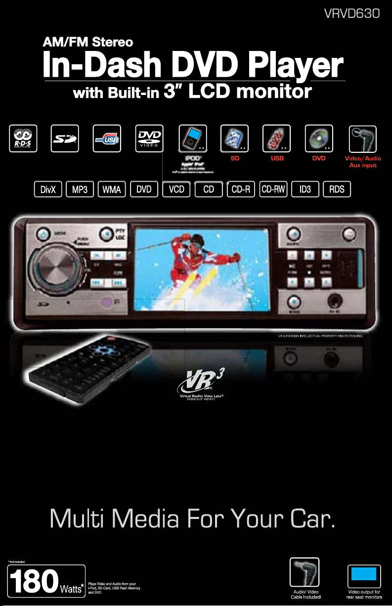
CONGRATULATIONS. The VRVD630 Multi-Media Headunit with AM/FM
Stereo Receiver, DVD, VCD, CD, and MP3 Player, Auxiliary Input Jack, SD
Card & USB Memory capability and Detachable Faceplate, when used as
described, will give you years of dependable service in your car, truck, RV, or
mini-van. We have taken numerous measures in quality control to ensure that
your product arrives in top condition and will perform to your satisfaction. In
rare event that your VRVD630 Multi-Media Headunit with AM/FM Stereo
the
Receiver, DVD, VCD, CD, and MP3 Player, Auxiliary Input Jack, SD Card &
USB Memory capability and Detachable Faceplate contains a damaged or
missing item, does not perform as specified, requires warranty service, or
you have an installation problem, DO NOT RETURN THIS PRODUCT TO THE
STORE. PLEASE CALL OUR TOLL FREE NUMBER FROM THE U.S.A. AND
ADA 1-800-445-1797 and ask to speak with a member of our technical
CAN
service team; or submit your questions by e-mail to customerservice@vr-
m and a member of our technical service team will respond by e-mail to
3.co
your questions. Our in-house technical service team will expedite delivery of
your part, advise you on installation, or help troubleshoot a problem with you.
If your product needs warranty service, our technical service team representative will help you obtain the fastest remedy possible under the warranty.
Contents
Precautions ..................................................................................................... 4
Safety Precautions .......................................................................................... 5
Disc & memory Types ..................................................................................... 6
Care of Discs ................................................................................................... 6
Before You Install ............................................................................................ 7
Parts ................................................................................................................ 7
Remove the Old Unit ....................................................................................... 8
Installation (DIN Front Mount) ......................................................................... 9
Installation (Vehicle’s Brackets) .....................................................................10
Wiring Connections ........................................................................................11
Location of Controls.......................................................................................12
Remote Control .........................................................................................13-14
sic Operation .............................................................................................14
Ba
Radio Operation ........................................................................................15-16
Menu Settings ...................................................................................... 17-19
AV
CD Operation ........................................................................................... 19-20
Disc Menu Operations ............................................................................. 20-22
a Disc/USB/SD/MMC/MP3/WMA Operation ...........................................23
Dat
System Setup ........................................................................................... 24-27
Playing MP3 Files ..................................................................................... 27-28
Frequently Asked Questions ..........................................................................28
Specications ................................................................................................ 29
Warranty ........................................................................................................ 30
3
Page 3

Important Information
Region Management Information
This mobile DVD Player is designed
and manufactured to respond to the
Region Management Information that
is recorded on a DVD disc. If the Region number described on the DVD
disc does not correspond to the Region number of this Mobile DVD Player,
this Mobile DVD Player cannot play this
disc.
®
iPOD
iPOD® is a registered trademark of Apple Computer Inc.
4
Page 4

SAFETY PRECAUTIONS
Driving a vehicle while viewing a video on this head unit
may violate motor vehicle laws, and may result in serious injury, property damage, or death!
Please read these important precautions
BEFORE attempting to install this unit.
• CAUTION: CLASS 1 LASER
DVD player is a Class 1 laser product.
However, this mobile DVD player uses a visible/invisible laser beam which could cause
hazardous radiation exposure if directed.
Be sure to operate the mobile DVD player
correctly as described in this manual.
• Use of controls or adjustments or performance of procedures other than those
specified herein may result in hazardous
radiation exposure.
• Do not open covers and do not attempt
to repair this product yourself. Refer servicing to qualified personnel.
• Disconnect the vehicle’s negative battery terminal before starting installation.
Consult the vehicle’s owner’s manual for
proper instruction.
•
The unit is designed for a 12 Volt DC nega-
tive ground operation system only. Before
installing the unit, make sure your vehicle
is a 12
Volt DC negative ground system.
•
Mark the polarity of the existing speaker wires
before disconnecting the old head unit.
•
Be sure to connect the color coded leads
according to the wiring diagram. Incorrect
connections may damage the unit or cause
the unit to malfunction or cause damage the
vehicle's electrical system.
•
Make sure all the connections are completely correct before turning on your unit.
• When extending the ignition, memory
backup or the ground cable, use 0.75mm
dia
meter (AWG18) or heavier automotive
grade cable to avoid wire deterioration or
damage to the wire coating.
•
To prevent short circuit, never put or leave
any metallic object inside the unit. If you
smell or see smoke, turn off the power
immediately and consult your dealer.
• Insert the unit until it is firmly locked
into mounting sleeve, otherwise it may
fall out.
This mobile
•
Be careful not to drop or shock the unit,
it may break or crack because it contains
glass parts.
• The unit is only designed for use with
4 speakers. Do not combine speaker
output wires for use with 2 speakers. Do
not ground negative speaker leads to the
chassis ground.
•
Do not open the top or bottom cover.
Opening the top or bottom covers
Modifying the unit will void the warranty
and
may damage the unit or cause the
unit to malfunction or cause damage to
the vehicle's electrical system.
• Pa
rking in direct sunlight will cause
higher temperatures inside the vehicle.
Do not operate in extremely high or low
temperatures. The temperature inside
the
vehicle should be between 32º F (0º
C) and 100º F (37º C) before turning on
your unit. Cool down the vehicle before
operating the unit
• The faceplate is a precision piece of
equipment that contains sensitive electronic components. Do not subject it to
excessive shock.
• When replacing the fuse(s), the replacement must be of the same amperage as
s
ho
wn on the fuse holder.
• Do not block this unit’s vents or heater
panels. Blocking them will cause excessive heat to build up inside the unit and
may result in fire.
•
After completing the installation and before
operating the unit, reconnect the battery
according to the manufacturer’s instructions. Then press the reset (RES) button
with a pointed object, such as a ball-point
pen to set the unit to its initial status.
• Do not touch the terminals of the faceplate or of the unit.
• If you have difficulty installing this unit in
your vehicle contact customerservice@
vr-3.
com or Call 1-800-445-1797
5
Page 5
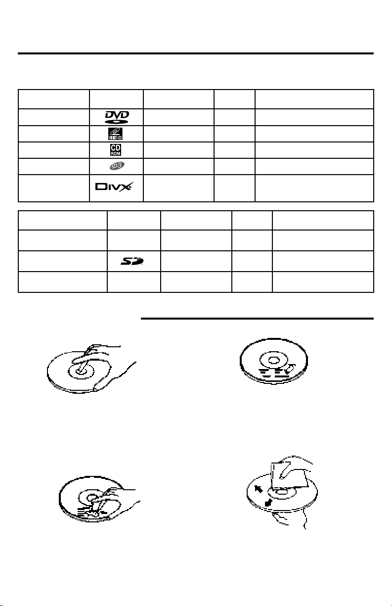
Disc & Memory Types
The following table contains information on the different functions performed, and the
different types of media used by this unit.
Disc Type Icon Content Size Playtime
DVD Audio/Video 12cm About 2 - 4.5 Hours
VCD Audio/Video 12cm
CD Audio 12cm
MP3 Audio 12cm
MPEG4
DIVX
Audio/Video
About 74 minutes
About 74 minutes
About 600 minutes
Memory Type Icon Content Size Playtime
USB Flash Memory Audio/Video
SD Card Audio/Video
MMC Audio/Video
Up to
2 Gigabytes
Up to
2 Gigabytes
Up to
2 Gigabytes
Depends size of les
Depends size of les
Depends size of les
Care of Discs
• Handle the disc by its edge to keep the disc
clean. Do not touch the disc’s surface.
• Do not use a CD with paste or ink residue
on it.
• Do not use CDs with labels or stickers
attached. The label may leave a sticky residue when it begins to peel.
• Clean the discs with an optional cleaning
cloth. Wipe each disc from the center out.
6
Page 6
Before You Install
Automotive audio equipment installations can be challenging at times, even to the most
experienced of installation technicians. If you are not condent working with electrical
wiring, removing and reinstalling interior panels, carpeting, dashboards or other components of your vehicle, please call our toll-free help line 1-800-445-1797 and our in-house
technical service team will answer your installation questions. Contact the vehicle's
manufacturer for vehicle specic instructions, or consider having the VRVD630 professionally installed.
IMPORTANT:
unit before installing.
• Before nal installation of the unit, connect the wiring temporarily,
making sure the unit and the system work properly.
• Use only the parts included with unit to ensure proper installation.
The use of unauthorized parts can cause malfunctions.
• Consult with your vehicle’s nearest dealership if installation re-
quires the drilling of holes or other modications of the vehicle.
•
Install the unit where it does not get in the driver’s way and cannot in-
jure the passenger if there is a sudden stop, like an emergency stop.
• The laser will be damaged if it overheats, so don’t install the unit
anywhere hot--for instance, near a heater outlet.
• If installation angle exceeds 30 from horizontal, the unit might not
give its optimum performance.
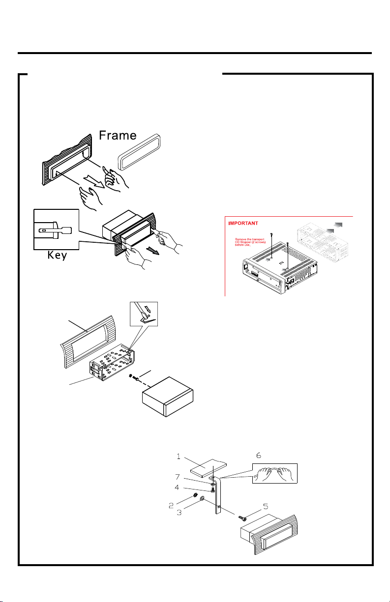
Remove the two transport screws from the top of the
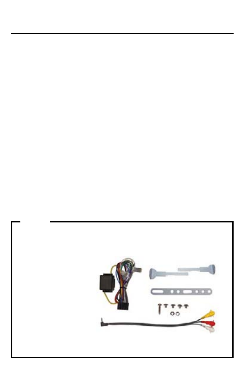
PARTS
Check All Included Parts Before You Start
Open the VRVD630 box and remove all parts, then check all parts and compare them to
the parts list. For replacement parts contact VR3 Customer Service at customerservice@
vr-3.com or call 1-800-445-1797.
2 - Keys
1 - Wiring Harness
1 - Lock Washer
4 - Screws
1 - Sheet Metal Screw
1 - Hex Nut
1 - Metal Support Strap
1 -
1/8" to RCA Audio/Video Cable
NOT SHOWN
1 - Remote Control
1 - Mounting Sleeve
1 - Faceplate Case
1 - Trim Bezel
7
Page 7
TAPE
FM
88 92 96 100 104 106 108
MHZ
AM
54 60 70 80 100 120 140160
x10KHZ
TUNE
UP
DOWN
AUDIO IN
CD/MP3
BAND
MUTE
LO/DX
AUTO STOP
Installation
GIVE US A CALL, WE'LL HELP YOU INSTALL.
1-800-445-1797
PLEASE DO NOT RETURN PRODUCT TO STORE.
Visit us on the WEB
www.vr-3.com
For Information and Technical Assistance,
Call Toll-Free in U.S.A. and Canada.
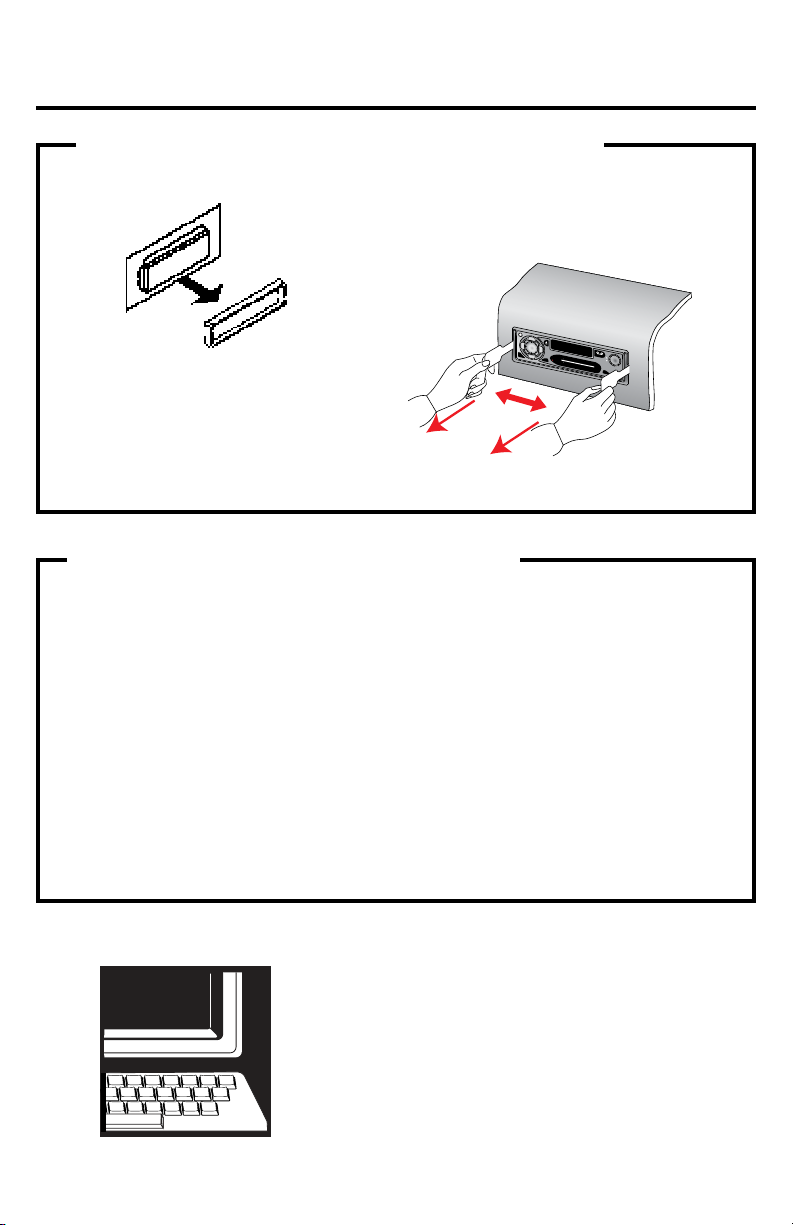
1. Remove the Old Unit from the Dashboard
A. Remove the outer trim frame.
B. Insert the buttons supplied with the old
unit into both sides of the unit as shown
in figure below until they click. Pull to remove the old unit from the dashboard.
DIN Front Mount
DO NOT DISCONNECT WIRES AT THIS TIME!
2. Mark Polarity of the Speaker Wires
Marking the polarity of the speaker
wires will make it easier to connect
the existing speakers to the VRVD630.
Consult the wiring diagram of the existing head unit before disconnecting any
wires. If a wiring diagram is not available
contact the head unit’s manufacturer.
While the old unit is playing, discon-
1.
nect the wires from one speaker.
2. Take a length of masking tape and
fold it around the wire so it forms a
flag.
3. On the masking tape mark the polarity of the speaker wires (+ & - ), as
well as left or right, and front or rear.
4. Double check that you marked the
first speaker correctly by checking
that the speaker wires are the same
at the head unit.
5. Repeat this procedure for all of the
speakers.
6. Mark the power, ground, and any
other wires also
.
8
Page 8
Installation
Remove the
half sleeve
A
E
2. Mounting
Sleeve
3. Screw
1. Dashboard
Ben d the tabs
to secur e the
Mou nting Slee ve
in the dashbo ard.
DIN FRONT-MOUNT (Method A)
IMPORTANT!
BEFORE THE FINAL INSTALLATION OF THE HEAD UNIT, CONNECT THE WIRING
TEMPORARILY, MAKING SURE THE UNIT AND THE SYSTEM WORK PROPERLY.
Insert ngers into the groove in the front
of frame to remove it.
Insert the buttons supplied with the old
unit into the grooves on both sides of the
old unit. The unit can be installed or removed from the dashboard using these
buttons. (Fig. 1)
Fig. 1
After inserting the Mounting Sleeve
into the dashboard, select tabs
on top, bottom, and sides, then
bend them to secure the mounting
sleeve in the dash board.(Fig. 2)
Fig. 2
Follow the diagram in Fig. 3
for installing the rear mounting
strap to the head unit. The rear
mounting strap will help keep
the head unit from moving
around inside the dashboard.
1. Dashboard
2. Nut (5mm)
3. Spring washer
4. Screw (5 x 25mm)
5. Screw
6. Strap
7. Plain washer
Fig. 3
9
Page 9
Installation
GIVE US A CALL, WE'LL HELP YOU INSTALL.
1-800-445-1797
PLEASE DO NOT RETURN PRODUCT TO STORE.
Visit us on the WEB
www.vr-3.com
For Information and Technical Assistance,
Call Toll-Free in U.S.A. and Canada.
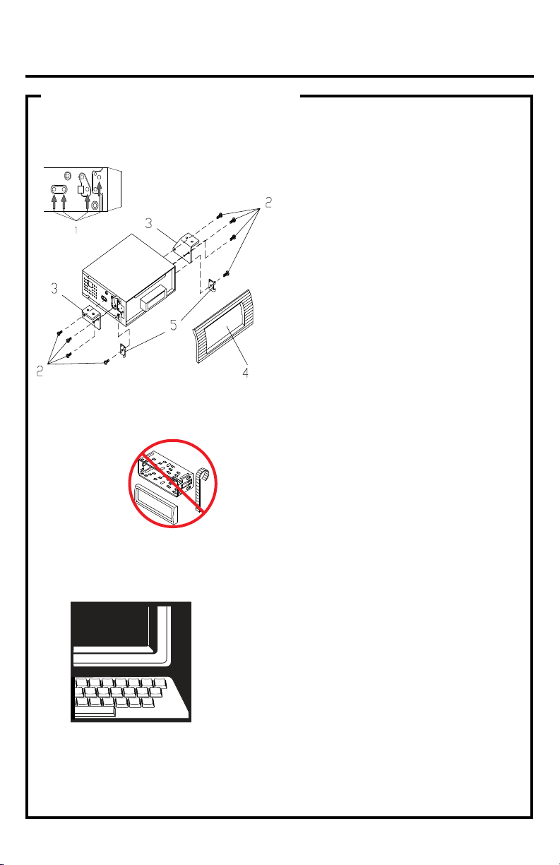
DIN REAR-MOUNT (Method B)
Installation using the screw holes on both sides of the unit.
1. Screw holes on the side of the unit.
2. Screws. Use either truss screws (5 x
8mm) or ush surface screws (4 x 8mm),
depending on the shape of the screw
holes in the bracket.
3. Vehicle’s Factory Mounting Bracket
4. Dashboard or Console
5. Hook (Remove this part)
Note: The mounting sleeve, outer trim
ring, and the mounting strap are not
used for this method of installation.
10
Page 10

Wiring Connections
White: Rear Left CH RCA output
Red: Rear Right CH RCA output
Green: Sub-Woofer output
Video Out 1
Video Out 2
RCA Out Left
RCA Out Right
Antenna
Socket
FUSE
YELLOW (+)
MEMORY
BLACK (-)
RED (+)
CONNECT YELLOW TO BATTERY OR LIVE + 12 VOLTS OF POWER
NEGATIVE GROUND -
12 VOLT NEGATIVE -
WHITE +
WHITE/BLACK -
GRAY +
GRAY/BLACK -
GREEN +
GREEN/BLACK -
VIOLET +
VIOLET/BLACK -
Front Left
Front Right
Rear Left
Rear Right
IGNITION ACC +
POWER ANTENNA OR AMPLIFIER
PARKING BRAKE
PINK/BLACK (-)
BLUE (+)
+ POSITIVE - NEGATIVE
Parking Brake
Indicator Light
Parking Brake Switch
Activated by Parking Brake
Parking Brake
Parking Brake Wire from Head Unit (PINK/BLACK)
Use a Wire Tap
or splice by hand
Negative
Negative Ground
Positive
To Chassis Ground or Metal Body Part
Battery
Operating a vehicle while watching a video on this head
unit may violate motor vehicle laws, and can cause
serious personal injury, property damage, or death!
VRVD630
CONNECTING THE PARKING BRAKE WIRE TO THE VEHICLE’S PARKING BRAKE SYSTEM.
The PINK/BLACK PARKING BRAKE wire MUST be connected to the parking brake
system of your vehicle. The unit will only play videos when the parking brake is
engaged, if the parking brake is not engaged, the screen will display the message “DISABLED WHILE DRIVING”. This is a safety feature designed to prevent the
driver from watching a video while driving.
NOTE: In Radio Mode or CD/MP3 Mode images will be displayed on the monitor
whether or not the parking brake is engaged.
11
Page 11

Location Of The Controls
1 2
1. Power / Mode
2. Volume +/- / MENU
3. TA (Trafc Announcement)/ST
4. PTY (Program Type)
5. AF
(List of Alternative Frequencies)
6. TFT LCD Display
7. #1 Pre-set / Play / Pause
8. AS / PS (Automatic Search & Program Search)
9. #2 Pre-set / Intro Scan
10. #3 Pre-set / Repeat
11. Faceplate Release Button
12. USB Slot
13. A/V IN Jack
3 4 5 6 7
8 9 10 11
17 15 14 13 12
16181920
14. #6 Pre-set / GO TO
15. #5 Pre-set / Stop
16. BAND
17. #4 Pre-set / Random
18.
Fast Forward / Tune+ / Track Up
19. Infra Red Window
20.
Fast Reverse / Tune- / Track Down
21. Eject Disc Button
22. Reset Button
23. Power Indicator LED
24. Disc Slot
25. SD Card Slot
2122232425
Audio/Video Auxiliary Input
The VRVD630 is equipped with an Audio/
Video Auxiliary Input on the front panel.
The Adapter has three RCA jacks, Yellow
for Video, and Red and White for the right
and left audio channels.
In order to use the Audio/Video Auxiliary
Input you MUST use the supplied Audio/
Video cable.
Insert supplied adaptor into the A/V Input
Jack on the front of the VRVD630.
Connect an A/V cable with male RCA plugs
to the supplied adaptor, then to a A/V device.
12
Page 12

Remote Control
Remote Control
1
2
3
4
5
6
7
8
9
10
11
12
13
14
15
Use and Care of the Remote
• Before using the remote control for the
1st time, please remove the clear strip from
the bottom of the remote control.
• This remote control is designed to be
used within 6 feet of the remote sensor on
the head unit, and within a range from 30°
left to 30° right of the Infrared sensor.
• If the sensor is in direct sunlight, it may
interfere with the ability of the remote to
control the head unit.
• This remote control is a precision device.
Point the remote control at the front
panel of the unit to operate.
1. POWER
2. DISP (Display)
3. A - B (repeat section from A to B)
4. RPT (Repeat Mode select)
16
18
20
22
24
26
28
30
5. ZOOM
6. Cursor (arrow) buttons: Fast Reverse / Fast
Forward, Previous Track / Next Track, Up
17
Down / Left / Right / Enter
7. ENTER
19
8. SETUP
9. TUNE/TRACK Down, Prev. Track
10. TUNE/TRACK Up, Next Track
21
11. TITLE (DVD Title Menu), PBC (Playback
Control Mode)
12. PLAY/PAUSE ( )
23
13. Numeric Buttons 1-6
14. # 7 BUTTON / TA
25
15. # 8 BUTTON / AF / REG
16. MODE (Input Mode select)
27
17. AUDIO (Audio Setup select)
18. SUBT (Subtitle Language select)
19. MUTE (turns Audio off )
20. ANGLE (Camera angle selection for
29
some
21. VOL +/-
22. MENU
t Forward ( )
23. Fas
24. Fast Reverse ( )
25. GO TO, AS•PS (Automatic Search /
Program Search)
26. STOP (
27. PROG (Programmed Play mode) LO/DX
(Local/Distance select)
28. RDM (Random Playback mode)
MO•ST (Stereo/Mono select)
29. #0 BUTTON / BAND
30. #9 / PTY (Program Type)
)
(Trafc Announcement)
Precautions
• Using batteries improperly can cause
them to explode.
• Keep the battery out of the reach of children. Should the battery be swallowed,
immediately consult a doctor.
• Should the battery be swallowed, immediately consult a doctor.
• Use one CR2025(3V) lithium battery.
• Remove the battery if the remote control
is not to be used for a month or longer.
• Do not short-circuit or disassemble
• Dispose of used batteries properly.
13
Page 13

Basic Operations
Changing the Battery
The remote control uses a lithium button
type battery, model CR 2025 3V. Do not
use any other kind of battery in the remote.
Follow these instructions when installing or
replace the battery.
Turn the remote
over, then slide the
battery holder out
of the remote.
Insert battery into
battery holder with
positive side of the
battery facing up.
Insert battery
holder into the remote control until
you hear a click.
Disp ose of A ll Bat ter ies Pr oper ly
Basic Operations
Initial System Start-Up
Be sure to press the RESET button when
using the unit for the rst time, after all connections are completed correctly.
1. Turn off the unit power.
2. Press the RESET button. The RESET
button on the housing must be activated
with either a ballpoint pen or similar pointed object. The RESET button is to be activated for the following reasons:
• Initial installation of the unit after all wiring
is completed.
• Some the function buttons do not operate.
• Error symbol appears on the display.
Turning Power ON and OFF
Turn on the unit by pressing button or inserting a disc in the DISC SLOT.
When system is on, press and hold the to
turn off the unit.
Warning LED
The LED will ash if the front cover is not
properly inserted into the main unit.
ESP Function
The unit features an anti-shock feature,
which buffers a certain amount of the recorded program into memory so that if the
unit skips due to rough road conditions,
the music or video will be uninterrupted.
The time of the buffered content varies depending on the disc type:
ec
CD, VCD ............................ 18 s
MP3 ................................. 160 seconds
DVD .....................................6 seconds
MPEG4 ..............................20 seconds
Mute Function
To turn off the sound instantly, press the
MUTE button. To return it to the prior sound
level, press MUTE again.
Mode Function
Press MODE repeatedly to switch between
DVD, AV and TUNER modes.
Adjusting the Volume Level
Rotate the Volume knob to adjust the
volume level.
Last Position Memory
• During disc playback, press and hold
the Power button to turn off the unit, when
you next turn on the unit, the DVD unit will
resume playing from the point that it was
interrupted.
• During disc playback, if you press MODE
to switch to a different mode, when you
next return to DVD mode, playback will resume from the point at which it was interrupted. Radio mode is the default mode
when the unit is star ted without any
discs or memory.
onds
14
Page 14

Radio Operation
VOLUME 25 AM 07:12
FM1 STEREO LOC
RADIO
107.15 M H Z 2
Selecting the Frequency Band
Press BAND button repeatedly to
select the desired radio band.
Stereo/Mono
Radio Screen
FM listening is generally done in Stereo mode. If the signal is weak or reception is not as good as you would
like, switching to Mono mode usually
improves the overall sound quality. To
switch to Mono mode, press ST (or
MO/ST on the remote control). Press it
again to return to Stereo mode.
Local/Distant
In urban settings, most stations are
strong enough to listening in LOCAL
mode.
However, if a station seems too distant
to be received well, try switching to
DISTANT mode by pressing and holding ST/LOC (or pressing LOC on the
remote control).
Press it again to return to LOCAL
mode.
Selecting Stations
ess a preset station button 1-6 to
1. Pr
select a station which has been stored
in the memory.
2. Press and hold the or buttons
until “MANU” appears on the screen,
then press the or buttons to select a station.
If the buttons have not been pressed
for several seconds, the unit will return
to automatic seek mode.
Automatic Memory Storage &
Program Scanning
• Automatic Memory Storing
This feature is used to automatically
set up presets for the radio.
Press and hold the AS/PS to start
1.
the tuner searching the frequency band
(FM1, FM2, FM3 & AM1, AM2) and storing the six strongest stations as presets.
• Program Scanning
After the presets have been recorded,
1. Press the AS/PS button and the
radio will scan the preset buttons in
order. It will play a station for a few
seconds, and then move to the next
station.
2. When you hear a station that you
wish to listen to, press the AS/PS button again to stop the scanning.
• Setting up Presets Manually
To set up the presets manually, tune to
the desired station using the
buttons.
When you nd a station you would like
to save to memory, press and hold the
desired preset button for a few seconds to store it.
and
RDS Operation
(Radio Broadcast Data System)
Setting RDS mode
Press AF/REG button to turn the RDS
mode ON/OFF.
Whenever RDS is on, symbol “AF” appears on the display.
Program name is displayed when receiving an RDS station.
“AF” starts blinking if the broadcasting
signals getting worse. “ALARM” will be
displayed when an emergency broadcasting is received, meanwhile sound
output level will be automatically adjusted to the preset output level when
the volume level is set at minimum.
15
Page 15

Radio Operation
AF (Alternative Frequencies) function
When the AF button pressed, AF switching mode is selected and the state of AF
switching mode is displayed by “AF” in the
display.
“AF” OFF: AF switching mode OFF.
“AF” ON: AF switching mode ON, and has
RBDS information.
AF Flashing on the Display:
AF switching mode is ON, but the RBDS
information is not received yet. When AF
switching mode is selected, the radio
checks the signal strength of AF all the
time.
The interval of checking time of each AFs
depends on the signal strength of the current station, from a few minute for a strong
station to a few seconds for a weak state.
Every time that a new AF is stronger than
the current station, it switches over to that
frequency for very short time, and new freque
ncy is displayed for 1-2 second.
Because the mute time of AF switching or
checking time is very short, it’s almost inaudible during the normal program.
During FM mode, when AF is on, SEEK,
AUTO-MEMORY function can only receive
and save the RBDS programs.
matically when the receiver is in a waiting reception mode and the audio signal is muted.
3. TA, TP will be displayed on LCD.
* When the trafc announcement is over,
the initial operation mode will be restored.
TA Interruption Function:
The current trafc announcement is cancelled by pressing the TA button. But the
TA search mode will not be off.
To Select Your Favorite Program Type
Press the PTY button to turn ON/OFF the
PTY list. After turning on the PTY list, the
list display as follows:
Press the / or / to select a desired
PTY item, then press the ENTER button to
search the corresponding PTY information,
and stops if the corresponding PTY information is detected. If the corresponding
information does not exist, it will display
“PTY NONE” and the PTY automatically
exits to normal mode.
REG (Regional Program) Function
Press and hold the AF/REG button to turn
Region Mode ON/OFF.
Some broadcasting stations change their
program from normal broadcasting to regional broadcasting for a certain time period.
When Region is ON, the current listening
program remains unchanged. When Region is OFF, it allows the receiver to tune to
the regional station.
TA (Trafc Announcement) Function
Press the TA button to turn the TA search
mode ON/OFF.
When TA search mode is on and a trafc
announcement is transmitted, the unit will:
tch automatically from any audio
1. Swi
mode to the trafc announcement.
2.
Switch on the traf c announcement auto-
NEWS
INFORM
SPORTS
TALK
ROCK
CLS ROCK
ADLT HIT
SOFT RCK
TOP 40
16
COUNTRY
OLDIES
SOFT
NOSTALG
JAZZ
CLASSICL
R B
SOFT R B
LANGUAGE
REL MUSC
REL TALK
PERSNLTI
PUBLIC
COLLEGE
WEATHER
TEST
ALART
Page 16

AUDIO
SYSTEM
TIME ON
TIME.M 12
AM 1 1: 00
PICTURE
SETUP
MAIN MENU
SETUP MENU
PICTURE MENU
BRIGHT 00 TINT 00
CONTRAST 00 DISP.M 4:3
COLOR 00 DEFAULT OFF
AUDIO MENU
VOLUME 00 FADER R.F
BASS 00 EQ CLAS
TREBLE 00 LOUD OFF
BALANCE L.R SUB.W ON
Ho ur
Mi nu te
CLOCK
AV Menu Settings
AUDIO MENU
VOLUME 00 FADER R.F
BASS 00 EQ CLAS
TREBLE 00 LOUD OFF
BALANCE L.R SUB.W ON
AV Menu Overview
You can adjust many of the unit’s settings from the AV MAIN menu.
The AV menu contains the menu items
and submenus shown in the gure below:
1.
Press the VOLUME/MENU knob on the
head unit, or the MENU button on the Remote Control to activate the AV menu.
2. Use the or buttons on the head
unit, or the Arrow ( ) buttons on
the Remote Control to select a menu
item (AUDIO, PICTURE, SETUP).
tate the Volume knob on the
3. Ro
head unit or use the VOL+/- buttons
on the Remote Control to increase
or decrease the AV charcteristic you
have selected.
4. Repeat steps 2 and 3 to adjust the
other items if necessary.
5. Press ZOOM or MODE to return to
previous menu.
6.
Press MENU to nish the procedure.
Audio Menu
1. Use the or buttons on the head
unit, or the Arrow buttons on the Remote
Control to select a menu item to adjust.
2. Rotate the Volume knob on the head unit
or use the VOL+/- buttons on the Remote
Control to increase or decrease the AV
charcteristic you have selected.
Volume level: 0 to 63
Bass level: -7 to +7
Treble level: -7 to +7
Balance: 15L to 15R
This setting adjusts the balance between
the left and right speakers.
Fader: 15R to 15F
This setting adjusts the balance between
the front and rear speakers.
Equalization: Flat, Classic, Jazz, Pop
Loudness: ON/OFF
Loudness introduces a special low and
high frequency emphasis at low listening
levels.
Subwoofer: ON/OFF
This unit is equipped with a subwoofer output. If you connect this output to a powered subwoofer or amp & subwoofer system, enable the output by selecting ON.
17
Page 17

PICTURE MENU
BRIGHT 00 TINT 00
CONTRAST 00 DISP.M 4:3
COLOR 00 DEFAULT OFF
SYSTEM
TIME ON
TIME.M 12
AM 11 : 00
SETUP MENU
H o ur
M i nu te
CLOCK
AV Menu Settings
Picture Menu
1.
Use the or buttons on the head unit,
or the Arrow ( ) buttons on the Remote
Control to select a menu item to adjust.
2. Rotate the Volume knob on the head
unit or use the VOL+/- buttons on the Remote Control to increase or decrease the
AV charcteristic you have selected.
Brightness: 0 to 63
Adjust this setting if the picture is too bright
or too dark.
Contrast: 0 to 63
Use this setting to adjust the contrast of
the picture.
Color: 0 to 63
Use this setting to adjust the color of the
picture.
Tint: 0 to 63
Use this setting to adjust the tint to make
colors appear most natural.
Disp.M: (Display monitor type)
Select a setting which is appropriate for
the monitor you are using.
Monitor Type
16:9: Select this when the aspect ratio of
your monitor is 16:9 (widescreen).
4:3: Select this when the aspect ratio of
your monitor is 4:3. If you view a wide
screen picture, black bars will appear to ll
the left and the right sides of the screen.
Default: ON/OFF;
Select this to restore to factory settings.
Setup Menu
1. Use the or buttons on the head
unit, or the Arrow buttons on the Remote
Control to select a menu item to adjust.
2. Rotate the Volume knob on the head
unit or use the VOL+/- buttons on the Remote Control to adjust the item you have
selected.
3. Repeat steps 1 and 2 to adjust other
items if necessary.
4. Press ZOOM or MODE to return to previous menu.
Time: ON/OFF
Turns the clock display ON/OFF.
18
Page 18

AV Menu Settings
Information
Display
Folders List
Files List
File Type
Time.M: 12 / 24
Use this setting to select 12 hour clock
mode or 24 hour clock mode.
Clock setting:
Use this menu item to set or make changes
to the time displayed on the clock.
Loading/Removing a Disc
1. Press the button to ip down the front
panel.
2. Insert a disc with the label side facing
up, the disc will load automatically.
The information for the current disc will be
shown on the screen.
* To eject the disc, press the button.
Disc Information Screens
When you insert a DVD Disc, a screen with
information similar to the one below will
appear when you press the SUB-T button:
Press the DISP button to display to the following screen:
For MP3/JPEG/MPEG4:
Use Arrow buttons ( ) to select a le
or folder, then press the ENTER button to
conrm your selection.
If you select a le it will begin to play.
If you select a folder its contents(les) will
be displayed in the le list on the right
side.
When you insert a CD, MP3, JPEG or
MPEG4 Disc, the following screen appears:
Single Track Selection
Press the button to skip to the previous
track or the button to skip to the next
track.
Press the button to fast reverse or the
button to fast forward. Return to normal
mode by releasing the button.
Pause Playback
Press the button
Press it again to resume playback.
Stopping Playback
Press the
Press the button to resume playback.
Press the button twice and then press
the button to stop playback and return
to the rst track on the disc.
19
to pause disc playback.
button once to stop playback.
Page 19

Disc Operation
Fast Forward/Fast Reverse
1. Fast Forward
Press the
of Fast Forward as follows:
Normal 2X 4X
Normal 20X 8X
In Fast Forward mode, press the button
return to normal playback.
2. Fast Reverse
Press the
of Fast Reverse as follows:
Reverse 2X 4X
Reverse 20X 8X
In Fast Reverse mode, press the
to return to normal playback.
Repeat
Use this function when you wish to repeat
a whole disc, a track or a directory on the
disc.
1. Pr
ess the RPT button to select the differ-
ent repeat modes.
2. For different kinds of discs, pressing the
RPT button has different effects.
For CD/VCD/SVCD:
REP 1 REP ALL REP OFF
For MP3:
REP 1 REP DIR REP ALL REP OFF
For DVD:
REP CHAPTER REP TITLE REP OFF
NOTES:
REP 1: Only one track (le) is repeated.
REP DIR: A single folder of tracks (les) is
repeated.
REP CHAPTER: A Chapter is repeated.
REP TITLE: A Title is repeated.
REP ALL: An entire disc is repeated.
REP OFF: Normal Mode.
Note: The Repeat feature is not supported
for VCD 2.0 discs when PBC (Playback
Control) is on.
A-B Repeat
A-B Repeat allows you to specify a sec-
button to increase the speed
button to increase the speed
button
tion of the current track to be repeated or
looped.
1. Pr
ess A-B button to set the starting point
of the section you wish to repeat.
2. Press A-B button to set the end point of
the section you wish to repeat.
The unit will repeat or loop the section of
the current track you’ve just chosen from
point “A” to point “B”. To return to normal
playback, press the A-B button again.
Playing in Random Order
Press the #4/RDM button on the head unit
or the RDM button on the remote control to
switch the random mode ON/OFF. In ran-
dom mode, tracks (les) on the disc will be
played in random order.
Intro Scan
Press the INTRO button to play the rst
several seconds of each track on the current disc. Press the button again to stop
Intro Scan and return to normal mode.
Disc Menu Operations
Menu-driven playback is possible while
playing a disc with menu-driven features
or when playing a VCD with PBC (Playback
Control).
1. Press the TITLE/PBC and a title list or
disc menu will appear on the monitor.
2. Use cursor buttons ( ) and the ENTER button on the remote control to select
the items you want on the menu.
* On some discs, you can select the items
with the number button.
Multi-subtitle language function
Some DVD discs have multiple subtitle languages, allowing you to select the subtitle
language recorded on disc.
Press the SUB-T button to switch between
the different languages recorded on the
disc.
Notes:
• Not all discs will allow changing the subtitle during playback. In these cases, select
20
Page 20

Operation
the desired subtitle language from the DVD
menu.
• There may be a delay before the selected
subtitle language appears.
• For some discs, the subtitles will be displayed even when this is set to off.
• The number of available languages varies
from disc to disc.
Multi-Audio Language
For DVD:
For DVD discs which have multiple language soundtracks, you can press the
AUDIO button to switch between the audio
languages recorded on the disc.
Notes:
• The number of available languages varies
from disc to disc.
• Some discs only contain one soundtrack
language.
• Not all discs will allow changing the subtitle during playback. In these cases, select
subtitle select mode from the DVD’s
menu.
For VCD/SVCD:
Some VCD/SVCD discs have multiple audio channels, You can press AUDIO to select the desired audio channel(s) to play.
STEREO: Normal stereo (left/ right) playback.
MONO L: Left audio channel only.
MONO R: Right audio channel only.
Notes:
•
Some discs only contain one audio channel
.
Notes:
• Some time may be required for the angle
to change.
• Depending on the disc, the viewing angle
may switch in one of two ways.
Seamless: The angle switches smoothly.
1.
2. Non-seamless: When the angle is
switched, a still picture is displayed rst,
after which the angle switches.
• The number of available viewing angles
varies from disc to disc.
• The function only works for discs having
scenes recorded at different angles.
ZOOM function
Press ZOOM button repeatedly to enlarge
or reduce the size of image according to
the disc as follows:
ZOOM 2 ZOOM 3 ZOOM 4
ZOOM 1/2 ZOOM 1/3 ZOOM 1/4
ZOOM OFF
In zoom in mode, press the buttons
to move the zoomed-in area.
Programmed Play Function
Press PROG during playback to activate the
programing editing interface as follows:
For VCD/SVCD/CD:
Multi-Angle Function
You can view the same scene at different
angles if the disc has been recorded with
multiple viewing angles.
Press ANGLE during playback. The following information will be shown:
This example indicates that you are cur-
rently viewing the rst of three available
camera angles. Press the ANGLE button to
select a different angle.
For DVD/MP3/MPEG4:
1. Use the Arrow buttons on the
21
Page 21

1 2 3
Operation
remote control to select the item that you
want to program. The item you selected
will be highlighted.
2. Input the track number that you want to
program using the number buttons (0-9) on
the remote control.
3. Pr
ess the cursor buttons to move
to the “PLAY” button and then press the
ENTER button to program the playback
sequence.
On Screen Display
Press and hold the SUB-T button during
playback to display information of the current disc on the screen:
For DVD Disc Information:
For VCD/CD/MP3/JPEG:
1. Disc type
2. Playback information
TT 1/3: Current title/ Total title
CH 1/1: Current Chapter/Total Chapter
TRK 9/18: Current Track/Total Track
3. Time indication
: Elapsed playing time of the disc
-: Remaining time of the disc
T : Elapsed playing time of the current title
T-: Remaining time of the current title
C:
Elapsed playing time of the current chapter
C-: Remaining time of the current chapter
Audio language or audio channel indication
4.
5. Subtitle language indication
6. View angle indication
Mute indication
7.
8. PBC indication (only for VCD with PBC)
9. Repeat playback indication
: One track repeat playback
: One directory repeat playback
: The whole disc repeat playback
: Exit repeat playback mode
GOTO
Press GOTO button, the screen will display
the following message.
FOR DVD:
FOR VCD/CD/MP3:
• To search for a particular Title, Chapter, or Track
1. Use the cursor buttons to highlight 1 (track number), 2 (chapter number),
or 4 (VCD track number).
2. Then enter a number with the number
buttons to input the desired Title/Chapter, Track, then press the ENTER button to
conrm your selection.
• To search for a particular point by
playing time
1. Use the cursor buttons to move
to 3 (time).
2. Use the number buttons on the remote
control to input the elapsed playing time
of the current title or of the disc, and then
press the ENTER button to conrm the selection.
22
Page 22

Artist & Song Title
(MP3 ONLY)
Track Number
Volume Level Clock
Playing TimeStatus
File Type
Information
Display
Folders List
Files List
File Type
Operation
Data Disc Play Operation
When you insert a data disc containing
audio (MP3), movie (MPEG4) or picture
(JPEG) les into the disc slot, the following
main menu will appear:
Press the TITLE button to change the
source. Press the DISP button on the remote control to switch to the following interface.
into the USB port, the DVD player will read
the USB ash memory automatically.
The unit gives priority to a disc or SD/MMC
card. If you insert a disc into the disc slot
or insert a SD/MMC card into the SD/MMC
card slot while playing from the USB device, the unit will play the disc or the SD/
MMC.
Press the
button to enter PRE-STOP
mode, then press the GOTO button to
switch to the USB playback mode.
Note:
DO NOT CONNECT AN iPOD OR ANY
OTHER TYPE OF A/V DEVICE TO THE
USB PORT.
When reading the USB ash memory,
please don’t unplug it while the unit is trying to read it. If the player is unable to read
the device, check if the device is in good
condition. You may also try removing the
device fully from the port, and reinserting
it again.
• The main unit can only support the standard USB-memory format approved by
Microsoft.
Use the cursor buttons to navigate
the screen and the ENTER button to select
item.
Press the TITLE to switch between AUDIO,
JPG and MOVIE playback modes.
Playback type icons:
AUDIO Playback mode (default)
JPEG Playback mode
MOVIE Playback mode
In JPEG mode or MOVIE mode, press the
(STOP) to return to the main menu.
USB Playback
DO NOT CONNECT AN IPOD OR ANY
OTHER TYPE OF A/V DEVICE TO THE
USB PORT.
This disc player features a front panel USB
interface. ONLY a USB ash memory with
music or video les can be inserted into this
port. When you insert a USB ash memory
Memor y Card Operation (SD/MMC)
This disc player features a SD/MMC memory card slot. When you insert a SD/MMC
card into the memory card slot, the DVD
player will read the SD/MMC card automatically.
The unit gives rst playback priority to the
card in the slot. If you insert a disc into the
disc slot while reading the SD/MMC card,
the unit will play the disc. Press the button to enter PRE-STOP mode, then press
the GOTO button to switch back to the
card reading mode.
Note: When reading the memory card,
please don’t touch or remove the card. If
the player is unable to read the card, please
check if the card is in good condition.
You may also wish to try removing the card
fully from the reader, and re-inserting it
again.
23
Page 23

SYSTEM SETUP
AUTO
PAL
NTSC
TV SYSTEM
SCREEN SAVER
TV TYPE
PASSWORD
RATING
DEFAULT
EXIT SETUP
SYSTEM SETUP
ON
OFF
TV SYSTEM
SCREEN SAVER
TV TYPE
PASSWORD
RATING
DEFAULT
EXIT SETUP
System Setup
AV IN Operation
This disc player offers you the option of
using the front panel auxiliary A/V input
connector to connect a video game, digital
camera /camcorder or other units you wish
to use in your mobile audio/video system.
To connect a video device to the auxiliary
A/V input, rst connect the cable provided.
Then press the MODE button to turn AV IN
mode ON or OFF.
Setup
In DVD mode, when the disc is playing or
in stop mode, press SETUP button to enter
the Setup menu.
en the SYSTEM SETUP ICON in the
1. Wh
upper part of the menu is highlighted, use
the
/ buttons to move between the dif-
ferent ICONS.
2. Press the
button to move the cursor
to the list of options below. Then you can
use the / buttons to move between the
different setup options.
3. Pr
ess or the ENTER button to move to
the list of setup options, and then use
/
buttons and ENTER button to adjust your
selection.
4. When nished press the SETUP button
to return to normal mode.
NOTE: When settings are changed the current settings are overwritten. Make note of
the current settings before making changes. If the vehicle’s battery is disconnected,
the settings will be cleared and will return
to the factory settings when power is next
applied.
System Setup
When you rst open the setup menu, you
will see the System Setup page:
TV SYSTEM
TV SYSTEM is used to select the TV output
mode. This player can play discs recorded
in either PAL or NTSC formats.
• Select NTSC format when the unit is connected to an NTSC TV.
• Select PAL format when the unit is connecte to a PAL TV.
• You can also choose AUTO SELECT,
which will sense the type of monitor attached to the output and select NTSC or
PAL as needed. If you know the type of
monitor, you should choose the type in this
menu rather than letting AUTO SELECT do
it for you. This is because there may be an
small undesirable delay and ickering of
the screen during the AUTO-SELECT process.
SCREEN SAVER
Like a computer monitor, video screens
can “burn in” if a still image is displayed
too long on the screen.
This unit features a “screen saver” which
produces a moving image to avoid burn-in,
only if SCREEN SAVER is enabled in the
Setup menu.
24
Page 24

System Setup
SYSTEM SETUP
TV SYSTEM
SCREEN SAVER
TV TYPE
PASSWORD
RATING
DEFAULT
EXIT SETUP
4 : 3 PS
4 : 3 LB
16 : 9
Letter-box Wide Screen
4 : 3
4 : 3
16 : 9
16 : 9
Picture Format
on Disc
Pan Scan
TV Screen Size
SYSTEM SETUP
TV SYSTEM
SCREEN SAVER
TV TYPE
PASSWORD
RATING
DEFAULT
EXIT SETUP
_ _ _ _
SETTING the TV TYPE
TV types can vary based on their aspect
ratio. The common monitors fall into one of
three categories: 4:3 (PS/Pan and Scan),
4:3 (LB /Letterbox) or 16:9 (Widescreen).
Playing a video recorded in one aspect ratio on a monitor with a different ratio can
result in some mismatches and undesirable display distortion or cutoffs.
Read the following to assist you in setting
up the TV type:
4:3 PS (PAN SCAN)
Select this when connected to a conven-
tional 4:3 size monitor. The picture will ll
the entire TV screen. However, due to the
mismatch in aspect ratio, parts of the movie at the extreme left and right sides will
not be visible when playing a 16:9 format
movie.
4:3 (LETTER BOX)
When you are playing a widescreen format
vid
eo on a normal (4:3) monitor, the best
way to view this is in (4:3) letterbox format.
You can see the full picture, but there will
be a black band at the top and bottom of
the screen.
16:9 (WIDESCREEN)
Select this format when connected to a widescreen TV.
PASSWORD
The Password system is used in conjunction with the Parental Controls settings to
prevent a young person from changing the
settings without permission. The factory
default password is 0000. If you wish to
change this, enter 0000 and when prompted, enter a different 4-digit number.
PARENTAL CONTROL LEVEL
Use this function to restrict the viewing of
movies to children of appropriate age levels.
4:3(Pan and Scan) format is the factory default setting for this player.
1. Press the / button to select “PASS-
25
Page 25

RATING RATING
1 KID SAFE 5 PG-R
2 G 6 R
3 PG 7 NC-17
4 PG-13 8 A DULT
_ _ _ _
LANGUAGE SETUP
OSD LANGUAGE
AUDIO LANG
SUBTITLE LANG
MENU LANG
DIVX[R] VOD
EXIT SETUP
System Setup
WORD” then press the ENTER button.
2. The password input mode is now activated. Use the numbers on the remote
control to input the 4-digit password, then
press the ENTER button. (The factory default password is “0000”)
3. Pr
ess the / button to select “RATING”
then press the ENTER button.
The restriction levels (parental levels) appear on the right.
4. Press the button to select the ratings
list (1 to 8).
5. Use the / buttons to select a rating,
then press the ENTER button to conrm
your selection.
6. When nished press the SETUP button
to return to normal mode.
DEFAULT
Select DEFAULT and conrm it to restore all
the System Settings to those programmed
at the factory, except the Parental Controls
and Password.
About Parental Controls
Commercially-recorded DVD discs have
parental level assignments. The range of
parental controls is from 1 to 8. In general,
this range corresponds to established movie rating systems. Movie rating systems may
vary depending on the country in which you
live. At the bottom of this page is a chart
showing the rating system and corresponding Parental Control ratings for the USA.
The DVD player can be set in a similar way.
If the DVD player’s parental level is set to 8
it will play all discs. If the player’s parental
level is set below 8, only discs with a lower
or equal parental level will play.
For example, if the DVD player is set to 5,
only discs with parental control ratings of
5 w
ill play. To play a disc with a higher
1number rating, you must change the DVD
player’s rating to a higher number.
Consider a disc that is suitable for most audiences, and is rated as level 2 for the most
part. However in the middle there are also
scenes rated at 5 and 7 (not suitable for
children). Alternative scenes with lower rat-
DVD
ing are included. The
player plays the
highest rated scene that the parental setting
allows.
A section of the disc can have several different sequences that vary in parental control
levels.
In the above example of a disc with parental
control, the DVD player will show a different
section depending on the parental control
level set in the player’s menu.
This way parents can control the content of
lms and there is no indication that any censorship has occurred.
Language Setup
When you open the language setup menu,
you will see the following screen:
This menu provides many choices for the
menu, DVD and subtitle languages. The
languages for the DVD player in its various
menus are set in different menus than those
choices you might make for the playback of
a particular disc. Please note that language
options vary from disc to disc, and some
settings may be unavailable on
some discs.
26
Page 26

Operation
_ _ _ _
AUDIO SETUP
AUDIO OUT
KEY
EXIT SETUP
_ _ _ _
DIGITAL SETUP
OP MODE
DYNAMIC RANGE
DUAL MONO
EXIT SETUP
OSD Languages:
English / German / Spanish / French / Portuguese / Italian / Russian / Polish
Audio Languages:
English / German / Spanish / French / Portuguese / Italian / Russian / Polish
Subtitle Languages:
English / German / Spanish / French / Portuguese / Italian / Russian / Polish
Menu
Languages
:
English / German / Spanish / French / Portuguese / Italian / Russian / Polish
Audio Setup
When you open the AUDIO menu, you will
see the following screen:
1. AUDIO OUT: Change among SPDIF/OFF,
SPDIF/RAW and SPDIF/PCM.
2. KEY: Change among b, -4, -2, 0, +2, +4, #.
Digital Setup
When you open the DIGITAL SETUP menu,
you will see the DIGITAL SETUP screen:
1. OP MODE: Change among LINE OUT/ RF
REMOD.
• LINE OUT: LINE OUT mode, with digital
dialog normalization.
• RF REMOD: RF REMODULATION mode,
with heavy compression and digital dialog
normalization.
2. DYNAMIC RANGE: Change among FULL,
6/8, 4/8, 2/8, OFF.
3. DU
AL MONO: Change among STEREO,
MONO L, MONO R, MIX MONO
Playing MP3 Files
What is an MP3 le?
MP3 (MPEG-1 Audio Layer 3) is a le compression standard prescribed by the ISO,
the International Standardization Organization and MPEG, which is a joint activity
institution of the IEC.
MP3 les contain compressed audio data.
encoding is capable of compressing
MP3
audio data at extremely high ratios, re-
ducing the size of music les to as much
as one-tenth their original size. This is
achieved while still maintaining near-CD
quality. The MP3 format realizes such
high compression ratios by eliminating the
sounds that are either inaudible to the human ear or masked by other sounds.
Compatible le systems
This device supports discs formatted
with ISO9660 level 1 or level 2. Under the
ISO9660 standard, there are some restrictions to remember. The maximum nested
folder depth is 8 (including the root directory). The number of characters for a
folder/le names are letters A-Z (all caps),
numbers 0-9, and ‘_’ (underscore). This
device also can play back discs in Joliet,
Romeo, etc., and other standards that conform to ISO9660. However, sometimes the
le names, folder names, etc., are not displayed correctly.
Viewing JPEG Files
When preparing a disc of jpeg images to
be view on the DVD player, please use the
following guidelines for optimum performance:
• The recommended image size is 640 x
27
Page 27

Frequently Asked Questions
480 pixels. If a le is recorded at a higher
resolution, the player must resample it,
which will cause delays in displaying the
image.
• Only “baseline” type JPEG images can
be displayed on this player. Ths is the typical format used in digital cameras and web
cameras. So be sure you are saving the
les in the proper format. If you play a progressive or lossless JPEG image, a black
screen will appear. When you next select a
baseline image, you may experience some
delays.
Playing MPEG discs
• This unit can play back MPEG 1 or 2 les
with the extension code <.mpg>.
dio stream should conform to MPEG1
• Au
Audio Layer 2.
Frequently Asked Questions
Q. I inserted a DVD disc, but it cannot be
played. The message “REGION ERROR”
is displayed.
A. DVD players and discs all have “RE-
GION CODES.” If the region code number
on the DVD disc does not correspond to
the region number of this DVD player, the
unit cannot play the disc.
Q. When I insert a DVD disc, there is a
window shown on the screen for me to
enter a 4 character password. Why?
A. The current disc has a “Parental Control” level, and the player’s parental level is
set below the level of the disc. To view this
disc, you should enter the correct password to play the disc normally.
NOTE: To set the “Parental Control” level,
please refer to “Parental Control Level”.
28
Page 28

Specications
GENERAL
Power Supply Requirements: .......................................................................... DC 12 V
Ground Type ...............................................................................Negative Chassis Ground
Bass (at 100 Hz) .......................................................................................................±10 dB
Treble(at 10 kHz) ......................................................................................................±10 dB
Maximum Output Power: .................................................................................... 180 Watts
RMS Power Output ..........................................................................................4 X 15 Watts
Fuse: ........................................................................................................ 15 Ampere (max.)
Load Impedance ..................................................................................................... 4 Ohms
Chassis Dimensions: ........................................................................... 7”W X 6.3”D X 2”H
Weight ......................................................................................................................1.55 Kg
DVD PLAYER
Signal to Noise Ratio: ............................................................................................ > 50 dB
Channel Separation: .............................................................................................. > 40 dB
Frequency Response: .................................................................................. 20Hz - 20 KHz
MONITOR SCREEN
TFT LCD Screen ....................................................................................................3 inches
Number of pixels: .................................................................................... 16,777,216 pixels
Resolution: ................................................................................................959 X 240 pixels
RADIO
olts
FM TUNER
Frequency range: .......................................................................................87.5 -107.9 MHz
IF: .......................................................................................................................... 10.7 MHz
Stereo Separation: ....................................................................................................>25dB
AM TUNER
Frequency range: .........................................................................................530 -1710 KHz
IF: ........................................................................................................................... 455 KHz
29
Page 29

Limited Warranty
VIRTUAL REALITY VIDEO LABS® products are designed and manufactured to provide a high
level of trouble-free performance. VIRTUAL REALITY VIDEO LABS warrants, to the original purchaser, that
date of original purchase. As part of our commitment to product excellence, VIRTUAL REALITY
VIDEO LABS and/or its afliates routinely improve the designs, materials or production methods
of its existing products. Because it is impractical to publicize all changes in every product, we
reserve the right to make such changes without notice.
CONDITIONS OF WARRANTY:
If during the 30 day warranty period your new product is found to be defective, VIRTUAL REALITY VIDEO LABS will repair such defect, or replace the product, without charge for parts or labor
subject to the following conditions:
1. All repairs must be performed by VIRTUAL REALITY VIDEO LABS and/or its afliates in Eatontown, New Jersey.
2. The equipment must not have been altered or been damaged through negligence, accident,
or improper operation.
3. The replacement of parts are exempted from this warranty when replacement is necessary
due to normal wear and tear.
4. All warranty claims must be accompanied by a copy of the sales receipt or bill of sale.
5.
Repair or replacement parts supplied by VIRTUAL REALITY VIDEO LABS under this warranty are
protected only for the unexpired portion of the original warranty.
6. In the case of car stereos, this warranty does not extend to the elimination of car static or motor noise; correction of antenna problems; costs incurred for the removal or reinstallation of the
product; damage to tapes, speakers, accessories or car electrical systems.
7.
VIRTUAL REALITY VIDEO LABS will not be responsible for any charge incurred for installation.
its products are free from defects in material and workmanship for 30 days from the
OWNER’S RESPONSIBILITIES:
VIRTUAL REALITY VIDEO LABS will make every effort to provide warranty service within a reasonable period of time. SHOULD YOU HAVE ANY QUESTIONS ABOUT SERVICE RECEIVED,
OR IF YOU WOULD LIKE ASSISTANCE IN OBTAINING SERVICE, PLEASE CALL TOLL FREE
1-800-445-1797, 8:30am - 4:30pm EST.
In order to provide you with the proper warranty service, we request that you adhere to the following procedure:
1. Include a copy of your sales receipt or bill of sale with your unit when it is returned for warranty service.
2.
If it is necessary to return your product for service, please return it securely packed, preferably in
the original shipping carton, and freight and insurance prepaid to the following address: VIRTUAL
REALITY VIDEO LABS, Service Department, 41 James Way, Eatontown, New Jersey 07724.
3. Please include a detailed explanation of the problem you are having.
4. If your product is found by VIRTUAL REALITY VIDEO LABS to have a defect in material or
workmanship, within the warranty period, it will be repaired or replaced at no charge and returned to you prepaid. Where permitted by Iaw VIRTUAL REALITY VIDEO LABS liability shall
be limited to that set forth in this warranty. This warranty shall be the exclusive remedy of the
purchaser.
VIRTUAL REALITY SOUND LABS® makes no other warranty of any kind, expressed or implied;
and all implied warranties, are hereby disclaimed by VIRTUAL REALITY VIDEO LABS and ex-
cluded from this warranty, VIRTUAL REALITY VIDEO LABS and/or its afliates, the manufacturer,
distributor and seller shall not be liable for any injury, loss or damage, incidental or consequential, arising out of the use or intended use of the product.
30
Page 30

©2008 Intellectual Solutions Inc., All Rights Reser ved, All designs, logos and images are the exclusive propert y of
Intelle ctual Solutions Inc. and/or its afliates. U.S. and Foreign Patents Pending. 031208 Printed in China 0000 0
 Loading...