

Page 1
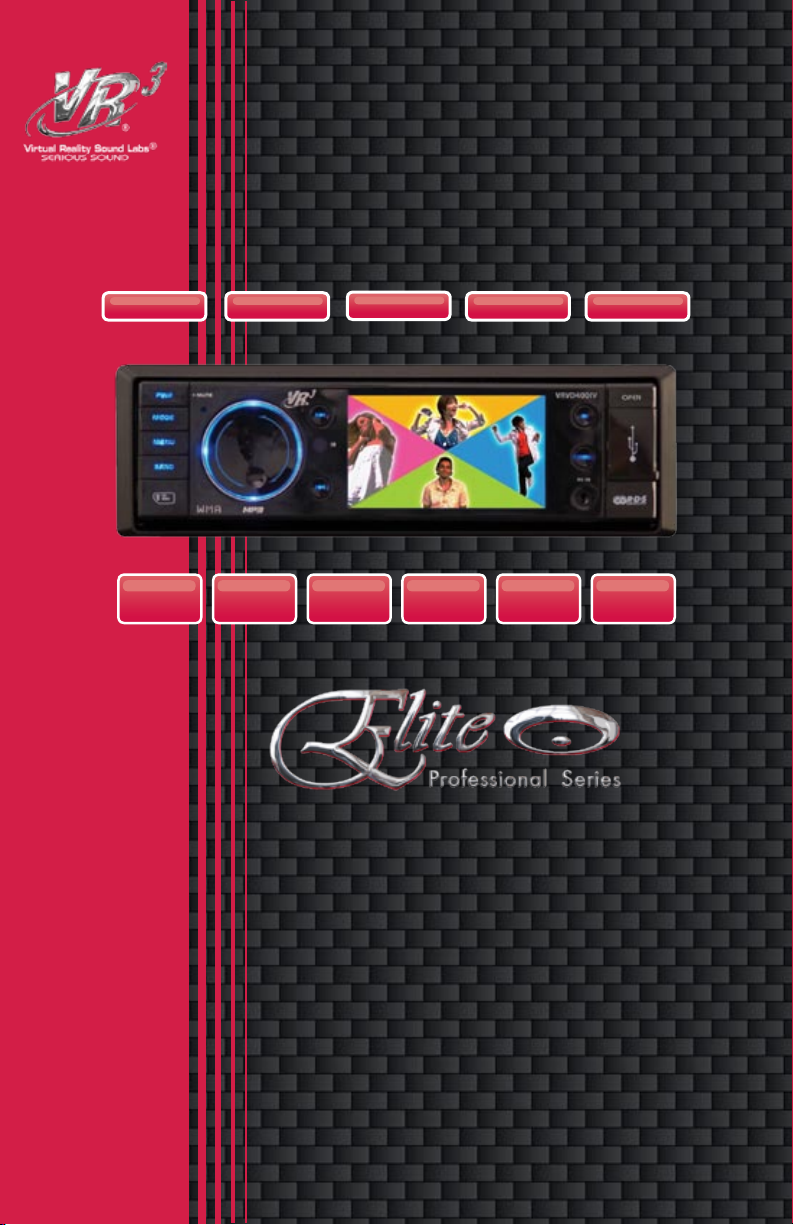
VRVD400IV
iPOD SD
USB
MP3 WMA JPEG
A/V Input
M-JPEG
RDS
ID3OGG
AM/FM Stereo
IPOD VIDEO/MP3/WMA/OGG PLAYER
180
WATTS*
Page 2

Welcome
Dear Customer,
CONGRATULATIONS. The VRVD400IV when used as described, will give you years of
dependable service in your car, truck, RV, or mini-van. We have taken exacting measures
in quality control to ensure that your product arrives in top condition and will perform to
your satisfaction.
In the rare event that your VRVD400IV is missing an item, contains a damaged part,
does not perform as specied, requires warranty service, or you have an installation
problem, DO NOT RETURN THIS PRODUCT TO THE STORE. PLEASE CALL OUR
TOLL FREE NUMBER FROM THE U.S.A. AND CANADA 1-800- 445-1797 and ask to
speak with a member of our technical service team; or submit your questions to
customerservice@vr-3.com and a member of our technical service team will respond by
email to your questions.
Our in-house technical service team will expedite delivery of your part, advise you on
installation, or help troubleshoot a problem with you. If your product needs warranty
service, our technical service team representative will help you obtain the fastest remedy
possible under the warranty.
Table Of Contents
Precautions .......................................................................................................3
File, Memory & iPod Compatibility ...................................................................4
Before You Install ......................................................................................... 5-6
Tools Needed to Install .....................................................................................6
Parts Included ..................................................................................................6
Wiring Diagram .................................................................................................7
Remove Old Head Unit ....................................................................................8
Mark Polarity of Speaker Wires .......................................................................8
Installation (DIN Front Mount) ..........................................................................9
Position of Controls ........................................................................................10
Remote Control .........................................................................................11-13
Menu Navigation .............................................................................................14
Operation ........................................................................................................15
Digital Tuner Operation .............................................................................14-15
SD/USB Operation ....................................................................................17-18
iPod Operations ........................................................................................ 19-21
Back-up Camera Input....................................................................................22
Subwoofer Output ...........................................................................................23
Specications .................................................................................................24
Warranty .........................................................................................................25
2
Page 3

PRECAUTIONS
Please read these important precautions BEFORE attempt-
ing to install this unit. Driving a vehicle while operating
this head unit may violate motor vehicle laws, and may
result in serious injury, property damage, or death!
• Disconnect the vehicle’s negative battery terminal before starting installation.
Consult the vehicle’s owner’s manual for
proper instruction.
• The unit is designed for a 12 Volt DC
negative ground operation system only.
Before installing the unit, make sure your
vehicle is a 12 Volt DC negative ground
system.
• Mark the polarity of the existing speaker
wires before disconnecting the old head
unit.
• Be sure to connect the color coded
leads according to the wiring diagram.
Incorrect connections may damage the
unit, cause the unit to malfunction, or
cause damage the vehicle's electrical
system.
• Make sure all the connections are completely correct before final in-dash of
your unit.
• When extending the ignition, memory
backup or the ground cable, use 1.02mm
diameter (AWG18) or heavier automotive
grade cable to avoid wire deterioration
or damage to the wire coating.
• To prevent short circuit, never put or
leave any metallic object inside the unit.
If you smell or see smoke, turn off the
power immediately and consult your
dealer.
• Insert the unit until it is firmly locked into
mounting sleeve, otherwise it may fall
out.
• Be careful not to drop or shock the unit,
it may break or crack because it contains glass parts.
• The unit is only designed for use with
4 speakers and a sub-woofer. Do not
combine speaker output wires for use
with 2 speakers. Do not ground negative
speaker leads to the chassis ground.
• Do not open the top or bottom cover.
Modifying the unit will void the warranty
and may damage the unit, cause the unit
to malfunction, or cause damage the
vehicle's electrical system.
• Parking in direct sunlight for several
hours will cause higher temperatures
inside the vehicle. Do not operate in
extremely high or low temperatures. The
temperature inside the vehicle should
be between 32º F (0º C) and 100º F
(37º C) before turning on your unit. Cool
down the vehicle before operating the
unit
• The faceplate is a precision piece of
equipment that contains sensitive electronic components. Do not subject it to
excessive shock.
• When replacing the fuse(s), the replacement must be of the same amperage as
shown on the fuse holder.
• Do not block this unit’s vents or heater
panels. Blocking them will cause excessive heat to build up inside the unit and
may result in fire.
• After completing the installation and
before operating the unit, reconnect the
battery according to the manufacturer’s
instructions. Turn the unit ON, then
press the reset (RES) button with a
pointed object, such as a ball-point pen
to set the unit to its initial status.
• Do not touch the terminals of the faceplate or of the unit.
• If you have difficulty installing this unit
in your vehicle, or you are missing parts
contact customerservice@vr-3.com or
Call 1-800-445-1797
3
Page 4
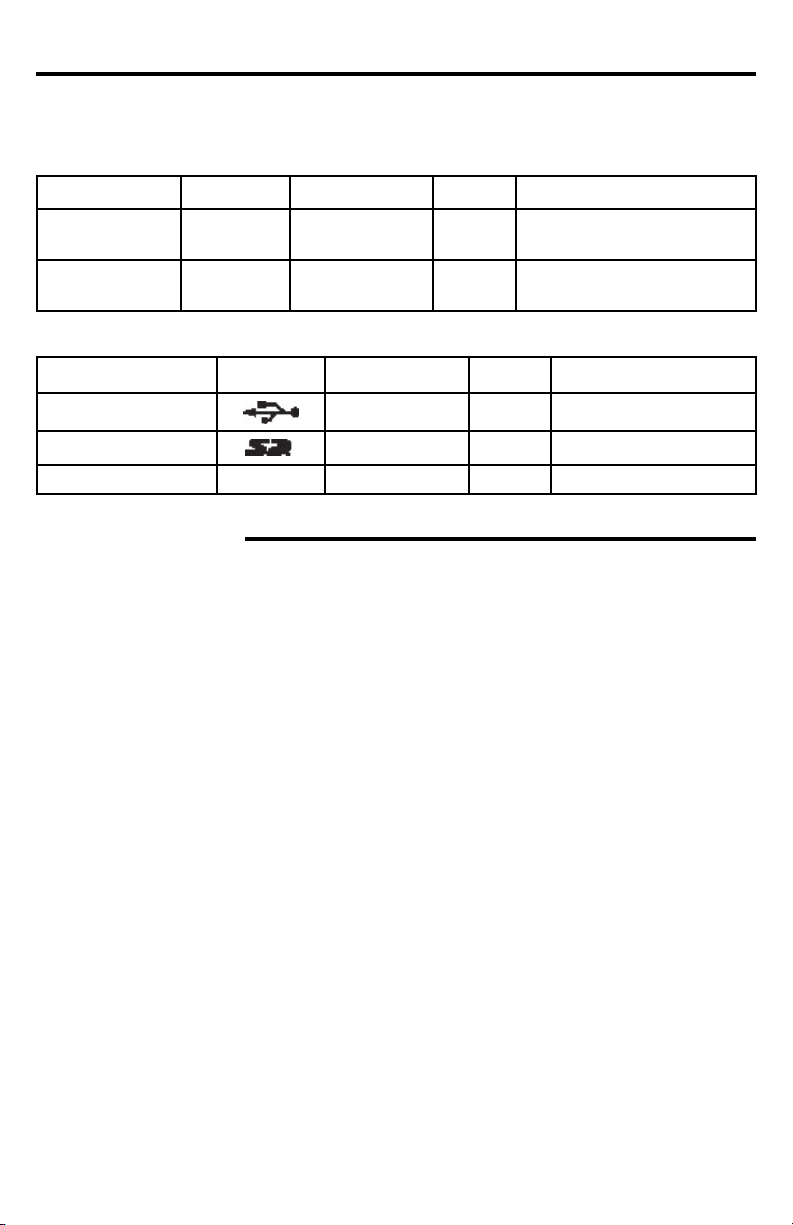
File Type, Memory & iPod Compatibility
The following table contains information on the different functions performed, and the different types of media used by this unit.
File Type Icon Content Size Playtime
MP3, WMA,
OGG
MPEG4
DIVX
Memory Type Icon Content Size Playtime
USB Flash Memory Audio/Video
Varies Audio Varies Varies with size of les
Varies Audio/Video Varies Varies with size of les
Up To 2GB
Varies with size of les
SD Card Audio/Video
MMC MMC Audio/Video
Up To 2GB
Up To 2GB
Varies with size of les
Varies with size of les
Compatible iPods
Model Software Version
iPod 4G ........................................................................................................................ 3.1.1
iPod 4G Photo/Color .................................................................................................... 1.2.1
iPod 5G ...........................................................................................................................1.3
Classic .......................................................................................................................... 1.1.2
Classic 2G .................................................................................................................... 2.0.1
Mini 1G ......................................................................................................................... 1.4.1
Mini 2G ......................................................................................................................... 1.4.1
Nano 1G ....................................................................................................................... 1.3.1
Nano 2G ....................................................................................................................... 1.1.3
Nano 3G ....................................................................................................................... 1.1.3
Nano 4G ....................................................................................................................... 1.0.3
iPod touch 1G ............................................................................................................... 2.2.1
iPod touch 2G ............................................................................................................... 2.2.1
4
Page 5

Before You Install
Automotive audio equipment installations can be challenging at times, even to the most
experienced of installation technicians. If you are not condent working with electrical
wiring, removing and reinstalling interior panels, carpeting, dashboards or other components of your vehicle, please call our toll-free help line 1-800-445-1797 and our in-house
technical service team will answer your installation questions. Contact the vehicle's
manufacturer for vehicle specic instructions, or consider having the VRVD400IV professionally installed.
• Before starting the installation, disconnect the negative battery cable from the
battery’s negative terminal.
• Before nal installation of the unit, connect the wiring temporarily, making sure
the unit and the system work properly.
• Use only the parts included with unit to ensure proper installation. The use of unauthorized parts can cause malfunctions.
• Consult with your vehicle’s nearest dealership if installation requires the drilling
of holes or other modications of the vehicle.
• Install the unit where it does not get in the driver’s way and cannot injure the pas-
senger if there is a sudden stop, like an emergency stop.
5
Page 6
Before You Install
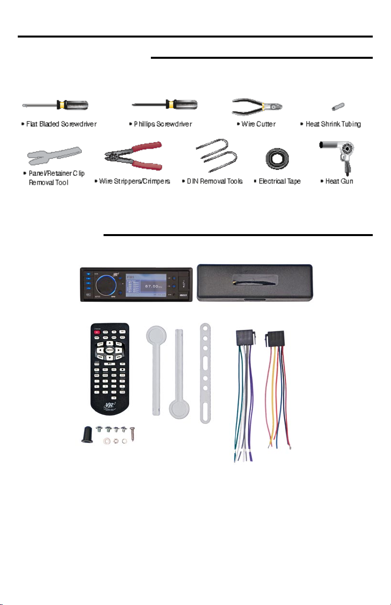
Tools Needed to Install
Below are the basic tools needed for most installations. Depending on the vehicle you may
need other tools to complete the installation. Tools Not Included.
Parts Included
Package will include the following parts & accessories for installation and operation of the unit.
1 - Faceplate
1 - Faceplate Case
1 - Remote Control
2 - Removal Keys
1 - Metal Mounting Strap
1 - Rubber
1- Sheet Metal Screw (B5x20)
4 - Screws (M5x6)
1 - Washer
1 - Lock Washer
1 - Hex Nut
1 - Power Wiring Harness
1 - Speaker Wiring Harness
1 - Head Unit (not shown)
3 - Foam Rubber Inserts for different iPod models (not shown)
6
Page 7
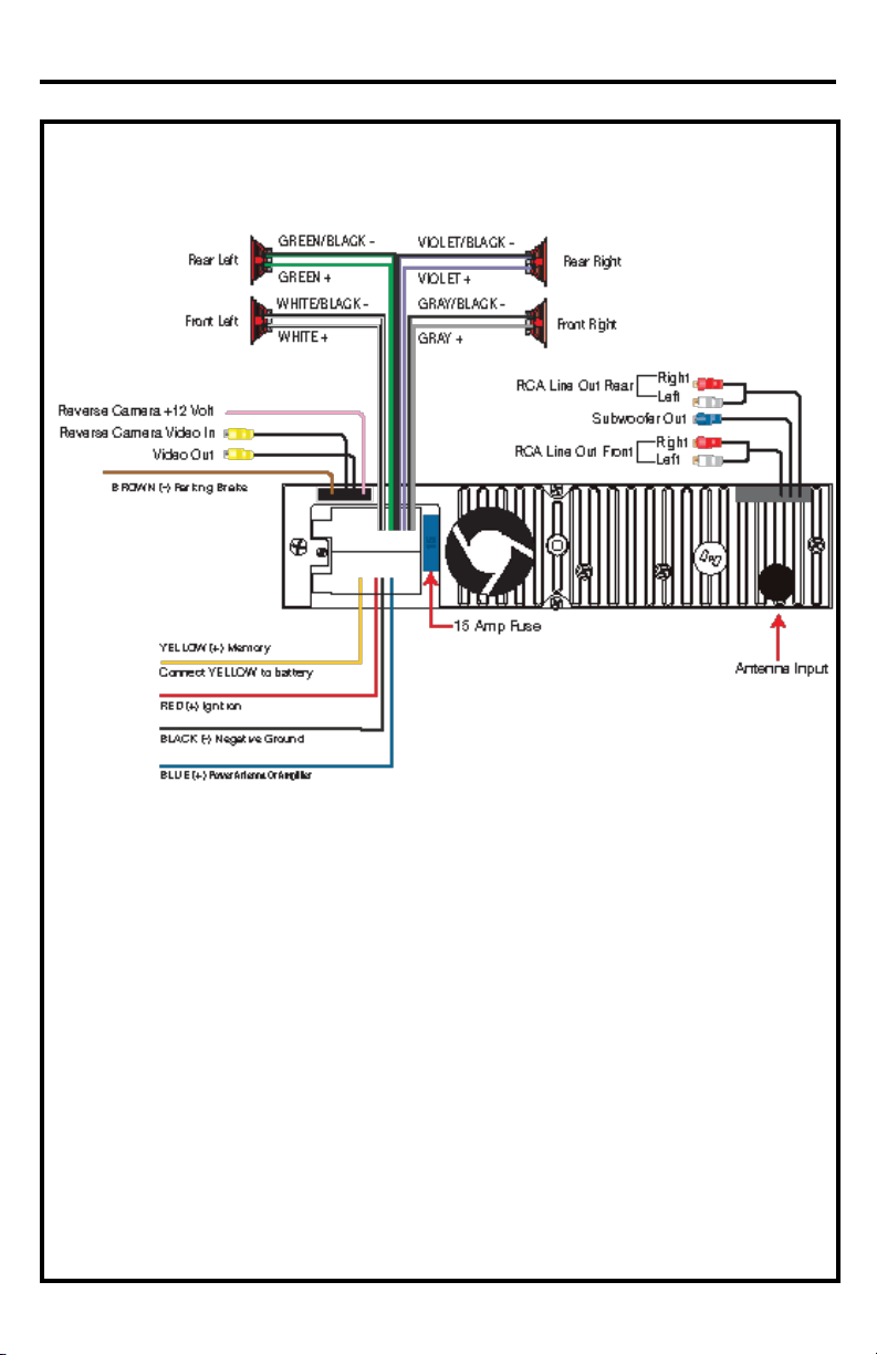
Wiring Diagram
Disconnect the vehicle’s battery
before installing this head unit.
IMPORTANT SAFETY WARNING
The Orange Parking Brake Wire MUST be connected to the negative wire of
the vehicle’s parking break. Virtual Reality Video Labs and/or its afliates
waives any and all liability when this wire is NOT connected as directed.
Driver can only watch a movie when the parking brake is ON.
• Before starting the installation, disconnect the negative battery cable
from the battery’s negative terminal.
• Before nal installation of the unit, connect the wiring temporarily, making sure the unit and the system operates properly.
7
Page 8
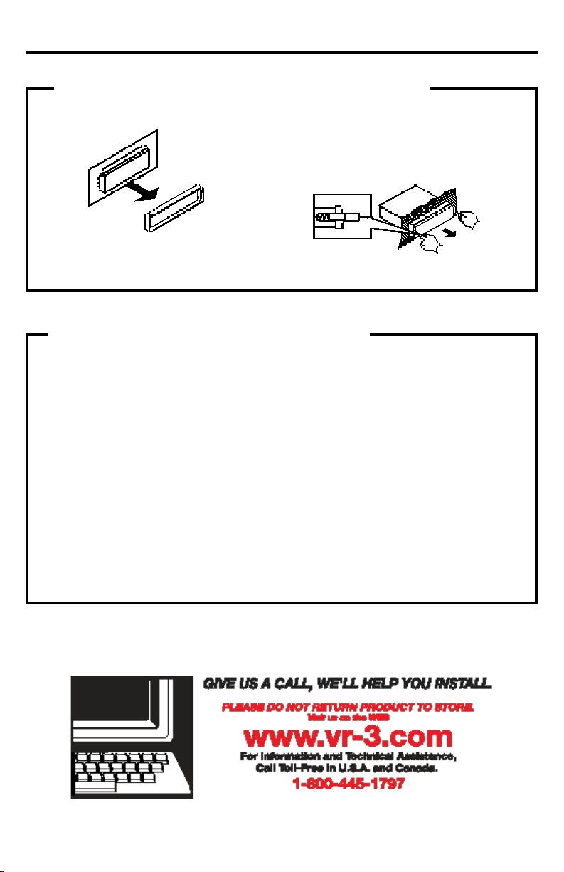
Installation
1. Remove the Old Unit from the Dashboard
A. Remove the outer trim frame.
DIN Front Mount
B. Insert the keys supplied with the old unit
into both sides of the unit as shown in figure below until they click. Pull to remove
the old unit from the dashboard.
DO NOT DISCONNECT WIRES AT THIS TIME!
2. Mark Polarity of the Speaker Wires
Marking the polarity of the speaker
wires will make it easier to connect the
existing speakers to the VRVD400IV.
Consult the wiring diagram of the existing head unit before disconnecting any
wires. If a wiring diagram is not available
contact the head unit’s manufacturer.
1.
While the old unit is playing, discon-
nect the wires from one speaker.
2. Take a length of masking tape and
fold it around the wire so it forms a
flag.
3. On the masking tape mark the polarity of the speaker wires (+ & - ), as
well as left or right, and front or rear.
4. Double check that you marked the
first speaker correctly by checking
that the speaker wires are the same
at the head unit.
5. Repeat this procedure for all of the
speakers.
6. Mark the power, ground, and any other wires also
.
8
Page 9

Installation
DIN FRONT-MOUNT (Method A)
IMPORTANT!
BEFORE THE FINAL INSTALLATION OF THE HEAD UNIT, CONNECT THE WIRING
TEMPORARILY, MAKING SURE THE UNIT AND THE SYSTEM WORK PROPERLY.
Insert ngers into the groove in
the front of frame to remove it.
Insert the keys supplied with the
old unit into the grooves on both
sides of the old unit. The unit
can be installed or removed from
the dashboard using these keys.
(Fig. 1)
Fig. 1
After inserting the Mounting Sleeve
into the dashboard, select tabs on
top, bottom, and sides, then bend
them to secure the mounting sleeve
in the dash board.(Fig. 2)
Fig. 2
Follow the diagram in Fig. 3
for installing the rear mounting strap to the head unit.
The rear mounting strap
will help keep the head unit
from moving around inside
the dashboard.
1. Dashboard
2. Nut (5mm)
3. Spring washer
4. Screw (5 x 25mm)
5. Screw
6. Strap
7. Plain washer
Fig. 3
9
Page 10

Position of Controls
1 2 3
15 16 17 18 19
5 678 9 10
4
FRONT PANEL
1. POWER/ MUTE
2. MODE
3. MENU
4. BAND
5. VOL Knob
6. NEXT
7. IR Sensor
8. PREVIOUS
9. LCD
10. AV Input Jack
11. MEM
12. OK
13. OPEN
14. USB Port
1112 13 14
INNER PANEL BEHIND FACEPLATE
15. SD/MMC Slot
16. IPOD BOX
17. IPOD EJECT
18. RESET
19. RED LED
10
Page 11

1. STANDBY/POWER
2. LOUD
3. ST/MONO
4. OSD
5. SETUP
6. Cursor
7. / PREVIOUS
FAST REVERSE
Remote Control
15. DSP
16. SUBWOOFER
17. MUTE
18. MODE
19. MENU
20. ENTER
/ NEXT /
21.
FAST FORWARD
8. LOCAL/RETURN
9. PLAY/PAUSE
10. SEL
-
11. VOL
12. BAND /RDM
13. GOTO/ AUDIO
14. NUMBER BUTTONS
(0-9)
22. INT
23. STOP
24. VOL+
25. A-B ZOOM
26. SUB-T
27. PROG/PTY
28. RPT/ P.SCAN
29. TA
Use and Care of the Remote
Aim the Infra Red LED of the remote control at the front panel of the unit to operate.
Precautions:
• Dispose of used batteries properly. Follow your local recyling laws.
• Using batteries improperly can cause them to explode.
• Keep all batteries out of the reach of children.
• Should a battery be swallowed, immediately consult a doctor.
• Use one CR2025(3V) lithium battery only.
• Remove the battery if the remote control is not to be used for a month or longer.
• Do not short-circuit or disassemble
• Do not drop the remote control, it may become jammed under the brake or accelerator pedals.
11
Page 12

Remote Control Operation
1. STANDBY/POWER
Turn the power ON/OFF.
2. LOUD
Press it to set LOUD on/off.
3. ST-MONO
In FM mode ONLY, press to select STEREO or MONO.
4. OSD (On Screen Display)
In Radio mode, press to show RBDS information on the display.
In SD/USB mode, press and hold to show
the current track / elapsed time, press and
hold again to clear track/ time information.
5. SETUP
Press once to open the system setup
menu. Press again to close system setup
menu.
Note: This Menu is for the SD card and
USB modes only.
6. Cursor Buttons / / /
Use the / / / buttons to select the
menu item.
Use the / buttons to select the title,
track.
Use the / buttons to show Next/Previous frame.
7. PREVIOUS/FAST REVERSE
Press to select the Previous Track, press and
hold to Fast Reverse x2, x4, x8, x20, play.
8. LOCAL/RETURN
In Radio mode:
Press to turn on “Local” to search for
strong frequecy bands.
In other modes:
Press this button to return to the submenu.
9. PLAY/PAUSE
Press to pause, press again to play.
10. SEL (volume knob)
Press to show audio menu BASS =>
TREBLE => BALANCE => FADER=> EQ,
use / buttons to select an item, then
press the ENTER button to enter setting
menu, use / to set audio data.
11. VOL -
Press this button to decrease the volume.
12. BAND/RDM
In Radio mode, press to select the a radio
band FM1, FM2 , FM3 , AM1, AM2.
In other modes, press the BAND/RDM button to use the Random function.
13. GOTO/ AUDIO
In USB/ SD mode, press and hold to show
GOTO menu, use the buttons 0-9 to input
a track/time to go to directly.
In USB/ SD/ IPOD mode, press to select
audio language. (This function needs audio
les that support multi-languages.) .
14. Number Buttons 0-9
In radio mode, select the desired band
(1~6). In USB / SD / IPOD mode, when
programming, select the desired items.
15. DSP
Press this button for audio setting, FLAT>
CLASSICS> POP> ROCK> DSP OFF.
16. SUBWOOFER
Press to set Subwoofer ON or OFF.
17. MUTE
Press to mute the sound level. Press the
MUTE Button again to cancel.
18. MODE
On the faceplate or remote control press
the mode button to change mode: Tuner>
USB> SD/MMC> AV IN> IPOD (if there is
a USB/ SD Card/ IPOD device connected.).
19. MENU
In iPod mode only, press to enter sub
menu directly, press this button and hold to
enter to select menu for music and video.
20. ENTER
Press it to conrm setting.
21. NEXT/FAST FORWARD
Press to select the Next Track, press and
hold to Fast Forward x2, x4, x8, x20, play.
12
Page 13

Remote Control Operation
22. INT
Press to activate the Intro function (plays
the 1st ten seconds of every track)
23. STOP
Press to stop playback.
24. VOLUME+
Press this button to Increase the volume.
25. A-B ZOOM
1. Press A-B button on the remote at the
starting point of the section you want to
repeat (point A).
2. Press A-B button again at the ending
point of the section you want to repeat
(point B). Section A-B repeating starts.
3. Press A-B button again to cancel the
A-B repeat function
Press and hold for 2 seconds to zoom the
image in or out when play video le.
26. SUB-T
Press to select sub-title language when
play video le (it need video les support
sub-title in multi languages).
27. PROG/ PTY
In Radio mode, press to activate the PTY
search.
In other mode, press to program your desired songs, display 1.--- 2.--- 3.--- ….16.--
--, input your desired song number, use the
/ / / buttons to move cursor and
input your desired song numbers.
Press the PLAY button to start play the
programmed items.
28. RPT / P.SCN
In Radio mode, press to scan all preset
stations in the memory of the current band
and play each memorized station for about
5 seconds. Press and hold this button to
search and store radio stations with the
best reception to the preset buttons automatically, then scan each preset stations
for about 5 seconds. In USB/ SD/ IPOD
mode, press to activate repeat function:
REP 1 , REP DIR (director) , REP ALL ,
REP OFF
29. TA (Trafc Announcement)
In any mode, press this button to set TA
ON or OFF.
Changing the Battery
Turn the remote over, then
slide the battery holder out
of the remote.
Insert battery into battery holder
with positive side of the bat tery
facing up.
Dispose of All Batteries Properly
13
Insert battery holder into
the remote c ontrol until
Page 14

Menu Navigation
Audio Setup
To Access Setup In iPOD or Radio Mode.
Faceplate:
Press the SETUP Button, then use the Volume Knob to navigate the choices on the menu and the
OK button to conrm your choice. This function is not availabe in iPod mode.
Remote Control:
Use the MENU button on the faceplate, or press and hold SETUP button on the remote control,
then use the arrow buttons on the remote control to navigate the menus and the ENTER button to
conrm you choice. This function is not availabe in iPod mode.
Use the MENU button on the faceplate or remote control to return to the previous menu.
MENU DESCRIPTION
AUDIO
BASS Supports +/-10 levels. Default level is 0.
TREBLE Supports +/-10 levels. Default level is 0.
BALANCE Supports 10 levels for each left and right channel. Default is left equal to right.
FADER Supports 10 levels for each front and rear channel. Default is front equal to rear.
EQ DSP OFF FLAT>CLASSICS>POP>ROCK>DSP>OFF
RBDS SETUP
TA ALARM/SEEK
TA VOL Supports 50 levels. Default level is 0.
EXPERT
DX/LOCAL Set search radio station by DX or LOCAL mode.
STEREO Set radio audio for STEREO or MONO mode, STEREO/MONO
BEEP Sets sound of button press. 2ND>ALL>OFF
LOUD Set loudness on or off. OFF/ON
SUB-WOOFER Set Sub Woofer output on or off. OFF/ON
BACKLIGHT Set OSD BACKLIGHT:MID>HIGHT>LOW
OSD COLOR Set OSD COLOR:DARK BLUE>VIOLET>LIGHT BLUE
CLOCK
CLOCK Set CLOCK display time or not. Off / on.
CLOCK ADJUST Set CLOCK ADJUST time
PICTURE
RED Adjust level of red color. Default level is 25. Supports 50 levels.
GREEN Adjust level of green color. Default level is 25 Supports 50 levels.
BLUE Adjust level of blue color. Default level is 25. Supports 50 levels.
BRIGHTNESS Adjust screen brightness. Default level is 25. Supports 50 levels.
CONTR AST Adjust screen contrast. Default level is 25. Supports 50 levels.
SHARPNESS Adjust screen sharpness. Default level is 10 Supports 15 levels.
SCREEN Adjust screen size: 16:9 > 4:3 > FULL
COLOR RESET Resume color default status.
Select YES or NO with the / buttons, and press the ENTER button to conrm “YES”.
Video Setup
14
Page 15

Operation
RESET THE UNIT
In case the unit has malfunctioned or
needs to be reset to factory default settings, press the RESET button under the
panel then the unit will be reset.
POWER BUTTON
Press any button except OPEN button to
turn on the unit.
Press and hold the POWER button to
power off the unit.
MODE BUTTON
Change the mode in the following sequence: Tuner>USB>SD/MMC>IPOD>AV
IN>Tuner
(When USB/ SD CARD/ IPOD available.)
MENU BUTTON
Press to enter MENU setting.
BAND BUTTON
In Radio Mode: Press to select FM1, FM2 ,
FM3 , AM1, AM2.
In USB/SD Card mode: Press to move cursor left/ right to select item.Same function
as the / buttons on remote control);
Press and hold to move cursor up / down
to select items. Same function as the /
buttons on the remote control.
VOLUME CONTROL
Turn the knob clockwise to increase the
volume level, turn counter-clockwise to
decrease the volume level. In menu mode,
turn VOL knob to select the previous item
or the next item.
OK BUTTON
In Radio mode, press to enter and conrm;
press and hold to set TA ON/ OFF.
MEM BUTTON
In Radio mode, press to select preset stations PRESET 1-6; press and hold to set
AF ON/ OFF. In USB/ SD CARD mode,
press to pause/ play. Press and hold to
stop. In IPOD mode, press to pause/ play.
MUTE FUNCTION
Press the POWER/MUTE button on the
faceplate or press MUTE button on the
Remote Control to mute. Press it again to
cancel mute.
AUDIO SETTING
Press the MENU button on the faceplate
or press the SEL button on the Remote
Control to select the audio setting:
BASS =>TREBLE => BALANCE =>
FADER => EQ.
Press the / buttons on remote to select
the audio setting, or rotate the VOL knob
on front panel to select the setting.
Press the OK button on the faceplate or
the ENTER button on the Remote Control
to choose the selected item.
Press the / buttons on remote or rotate
the VOL knob on the front panel to adjust
the audio setting.
Press the MENU button on the faceplate or
the SEL button on the Remote Control to
save the setting data and return to current
mode.
Notes: If you turn the unit off with the PWR
button, all the settings of each mode will be
saved.
- If you disconnect the battery or the power
wires of the unit, all the settings will be
cleared and become factory default setting.
- If you don’t adjust setting within 3 sec-
onds after selecting the desired setting
item, the unit will automatically return to the
current mode.
15
Page 16

Digital Tuner Operation
ON-SCREEN DISPLAY (OSD)
Press the OSD button to show the current
information of the Radio.
BAND SELECTION
Press MODE button to select the RADIO
mode.
Press the BAND button to select the desired band: FM1, FM2, FM3, AM1, AM2
MANUAL/ AUTOMATIC TUNING
Manual Tuning
Press and hold the / buttons on
remote control for 2 seconds to enter the
manual tuning mode. The word MANUAL
will be shown on the screen.
Press the / buttons on the Remote
to select a station.
Automatic Tuning
Press and hold the / buttons on the
front panel, the automatic search will start.
It will play the rst station with a strong
signal.
PRESET STATIONS 1-6
To save a Pre-set: during manual turning or
automatic tuning, press and hold the number
1-6 buttons on remote to store the preset
station 1-6 or press MEM button on front
panel and rotate VOL knob to select the preset station 1-6 and press OK button to store.
To choose a Pre-set: Press number button
1-6 on remote or / buttons on front
panel to play the preset station 1-6.
Note: You can store up to a total of 30 radio
stations in the memory (18FM, 12AM).
AS (AUTO STORE) / PS (PRESET SCAN)
AS (Auto Store)
In Tuner mode, Press the RPT/P.SCN button on the remote and hold for 2 seconds
to store radio station’s with the best reception to the preset buttons automatically.
PS (Preset Scan)
In Tuner mode, press this button to scan
the preset memorized stations, each preset
will scan for 5 seconds. Press again to stop
operation.
DIGITAL TUNER
Note: RBDS service availability varies with
areas. Please understand if RBDS service
is not available in your area, the radio will
not receive RBDS data.
TA (TRAVEL ANNOUCEMENT)
TP
(TRAVEL PROGRAM IDENTIFICATION)
Enable or disable TA mode:
(Default is OFF)
1) In any mode, press TA button on the
remote or press and hold OK button on
faceplate to activate the Trafc Announcement function. Press TA button again to
turn off the TA function.
2) When the TA function is activated it
will automatically search a station with TA
information. If there is no TA information, it
will automatically search for a station with
TP information, if there is no TP information either, it will return to the previous
station after searching.
3) When receiving a station with TP infor-
mation, TP icon is on.
When the unit is in another mode, such as
SD, USB or AUX IN, and TA information
is received, it will automatically change
to radio mode. After the TA is nished it
will return to the previous mode. Press TA
button on the remote or press and hold the
OK button on the faceplate once to ignore
the received TA information, press twice to
turn off the function.
PTY (Program Type)
Enable or disable PTY search.
(Default is OFF)
1. Press PTY button to display PTY list.
2. Press buttons 1 - 6 to select the program
type PTY will search for and start auto
search.
3. Repeat pressing PTY button to display
all PTY lists.
16
Page 17

SD Card & USB Operation
USB FLASH MEMORY
To play MP3/ WMA/ OGG les from a
USB ash memory, insert a USB ash
memory into the USB port on the right side
of the unit. The unit will start playing MP3/
WMA/ OGG les on the USB ash memory
automatically. Or press the MODE button
to select USB.
SD CARD
To play MP3/ WMA/ OGG les on an SD
card, insert an SD card into the SD card
slot (you should press the OPEN button on
the panel to ip down front panel and insert
the SD card into SD slot.) The unit will start
playing MP3/ WMA/ OGG les on the SD
card memory automatically. Or press the
MODE button to select SD card.
PAUSE/ PLAY
Press the PLAY/ PAUSE button to pause
the playback. Press the button again to
resume.
STOP
Press the STOP button on remote to
stop playback. Press the PLAY/ PAUSE
button to resume. If the SD card or USB
is removed, the resume function will be
cancelled.
Press the STOP button twice to stop the
playback totally. Press the PLAY/ PAUSE
button to start playback from the beginning.
SELECTING TR ACKS
If the MP3/ WMA/ OGG les are stored
in folders on the USB drive or SD Card,
the unit will start by playing the rst song
in the rst folder. After playing all the les
sequentially in the rst folder , the unit
will play all the les sequentially in the
next folder. The unit will continue playing
through all of the folders on the USB drive
or SD card in this manner.
Press the button to play the previous
track/chapter.
Press the to play the next track/chapter.
Press the Number buttons (0-9) to select
the desired track/chapter.
On faceplate, press the Band button to
move cursor from the folder list to the le
list, then to the le type icons on the bot-
tom of the screen.
Press to move cursor left/ right to select
item. Same function as the / buttons on
remote control.
Press and hold to move cursor up / down
to select items. Same function as the /
buttons on the remote control.
Fast Forward / Reverse
Press and hold o for two seconds
to start Fast Forward or Reverse 2x, press
and hold for two seconds again for 4x,
repeat this operation for 8x, 20x, normal
speed. Press the PLAY/PAUSE button to
return to normal playback.
Note: When using Fast Reverse or Forward in SD or USB mode, the unit will
resume normal operation at the end of the
current track.
REPEAT
Press the RPT button on remote for REP
1 (repeat the current playing le), REP DIR
(repeat current folder), REP ALL (repeat all
folders), REP OFF.
17
Page 18

Operation
REPEAT A-B FUNCTION
1. Press A-B button on the remote at the
starting point of the section you want to
repeat (point A).
2. Press A-B button again at the ending
point of the section you want to repeat
(point B). Section A-B repeating starts.
3. Press A-B button again to cancel the
A-B repeat function.
RANDOM
Press the RDM button on remote to play all
song tracks in random order.
Press again to cancel.
Note: Only for audio les.
Intro playback
Press the INT button on remote to play the
beginning of every track for 10 seconds in
sequence. Press again to cancel INT play.
Note: This function is only for audio les.
PROGRAMMING THE PLAYBACK
1. Press PROG button on the remote to
start programming.
2. Use / / / buttons to select the
program position and use digit 0-9 buttons
to select the desired track.
3. Press PLAY/ PAUSE button to program
play, or move the cursor to select PLAY
and press ENTER to play.
4. Move the cursor to CLEAR on program
menu, press ENTER to delete the programmed list.
5. Press PROG again to cancel program
play.
SELECTING AUDIO MODES (ONLY FOR
MP4 FILES)
Press AUDIO button on the remote repeatedly to select the audio language.
Press AUDIO button on the remote repeatedly to select the following modes:
L R STEREO (Channel left > Channel right
> Stereo).
Note: Multi-languages should be available
in the audio of MP4 les.
CHANGING THE SUBTITLE LANGUAGE
(ONLY FOR VIDEO FILES)
Press SUBTITLE button on the remote to
select the preferred language for sub-title.
Note: Multi-languages should be available
in the sub-title of Video les.
ZOOM (only for VIDEO les)
Press ZOOM button and hold for 2 seconds on remote to activate zoom function in the following sequences: ZOOM
2 => ZOOM 3 =>ZOOM 4 => ZOOM
1/2=>ZOOM 1/3=>ZOOM 1/4=>ZOOM
OFF.
ROTATE PICTURE (only for picture les)
In picture mode, press the or buttons
to rotate picture 90 degrees.
CHANGING PICTURE DISPLAY (only for
picture les)
In picture mode, press PTY button to
change the way pictures are displayed.
SYETEM MENU
In USB/ SD card mode, press SETUP button on remote to show system menu. Press
/ / / buttons to set system data,
press this button again to save input data
and exit the system menu.
18
Page 19

IPOD Operation
For a list of the iPods compatible with
this unit see page 4.
CONNECTING AN IPOD
1. Press the OPEN button on the face plate
and lower the face plate.
2. Press the REL button to release the
iPod compartment. Fig.1
Fig.1
3. Remove the iPod compartment. Fig.2
Fig. 2
4. Connect the iPod to the iPod plug in the
iPod compartment. Fig.3
6. The head unit will turn the iPod ON and
switch to the iPod mode automatically and
the iPOD Connect screen will be displayed
as the iPod and head unit connect. Fig. 4
Fig. 4
Notes:
• Remove the iPod from the box when the
unit is not in use.
• When the iPod is connected to this head
unit, the controls on the iPod are not functional.
• To start IPOD MODE while in another
mode, press the MODE button repeatedly
to switch to iPod mode.
• If a song is playing on the iPod when it is
connected to this unit, it will continue playing after the connection.
• Some characters may not be correctly
displayed.
Fig. 3
5. Return the iPod compartment to its original position behind the faceplate.
19
Page 20

IPOD Operation
SELECTING TR ACKS
On the remote or face plate, press and
hold the MENU button for two seconds to
display SELECT MENU, press this button
again to cancel SELECT MENU.
Rotate VOL key on face plate or press the
/ buttons on remote to select MUSIC
or VIDEO, press the OK or ENTER button
to conrm and go to the sub-menu of MUSIC or VIDEO.
ELAPSE BAR(time)
In Music Mode, the Elapse Bar is always
displayed on the bottom of the screen.
In Video mode, press and hold the OSD
button on remote to show elapse bar
(elapse/ remain timing bar).
FAST FORWARD/ FAST REVERSE
P
ress the button or the button
more than 2 seconds to activate fast forward ( ) or fast reverse ( ).
REPEAT
On the remote, press RPT button to repeat
one current playing le, “ ” will appear
on the display.
Press this button again to repeat all les in
IPOD, “ ” will appear on the display.
RANDOM
On the remote, press RDM button to play
all the tracks in random order. “ ” will
appear on the display.
Note: This function is only for audio les.
DIRECT MODE
Direct Mode enables you to enter the track
number of a song you want to listen to.
Rotate the VOL knob on face plate or
press / button on remote to select item
in the submenu, press the OK or ENTER
button to playback.
Press the button to move to the next
track.
Press the button to move to the previous track.
PLAY/ PAUSE
Press the Play/Pause button on remote to
pause. Press the button again to resume
normal operation.
Use the Number buttons 0-9 on the remote
control to directly input the track number of
the song you wish to listen to.
For example: If you have 82 tracks, press
the number 4 button on the remote control,
4/82 is displayed at the top of the screen
and track 4 will automatically begin to play.
20
Page 21

IPOD Operation
PAGE UP/ DOWN
On the remote, press the or buttons for
page up/down.
Note: The Page Up/Down feature does not
function if the displayed list does not have
more than 6 items.
DIRECT GO TO SUB-MENU
On the remote, press MENU button for direct go to the sub-menu of MUSIC/ VIDEO.
COMPATIBLE FILES
1. Audio les: MP3, WMA, OGG
2. Video les: DivX TM1 3.11, 4X, 5X and
6X versions
Nero Digital TM2
Screen for iPod Audio Files
Total Number of Tracks
Track Number
Song
Artist
Album
Real time MPEG2 MP@ML display
Real time MPEG1 D1 (720X480X30/
720X576X25) decoding
Playback Status
Elapsed Time
Elapsed Time Bar
Remaining Time
Current Time or Volume
(not displayed at the same time)
21
Page 22

Back-up Camera Input
BACK-UP CAMERA INPUT
(RCAM_VIN)
(Back-up camera not included)
This unit is equipped with a back-up
camera input to receive video signals from
a back-up camera. A back-up camera is
used to observe the area or “blind spot”
behind the vehicle when you are operating
your vehicle in reverse gear.
Please connect your back-up camera’s
video output to the back-up camera
input(RCAM_VIN) on the rear of the unit.
Connect the reverse wire (RCAM_+12V)
with the vehicle’s back-up light circuit.
Rear view camera picture will be enabled
when you are backing the car.
22
Page 23

Subwoofer Output
SUBWOOFER OUTPUT
To power a subwoofer you will need to
connect an amplier to the unit using the
subwoofer output.
The head unit sends only low frequency
signals to the subwoofer output.
Most single channel ampliers have both
left and right RCA input jacks which require
a “Y” adaptor to connect this head unit’s
subwoofer output to the amplier.
To Enable the Subwoofer Output
1. Press and hold the SETUP button,
choose EXPERT from the SETUP menu.
Or press the SW button on the remote
directly for SUBWOFFER ON/OFF.
2. On the EXPERT menu use the arrow
buttons to choose SUBWOOFER.
3.
Press the ENTER button on the remote
control to turn the SUBWOFFER jack ON or
OFF.
ANTI-THEFT SYSTEM
Removing the Faceplate
1. Press the PWR button to turn the unit OFF.
2. Press OPEN button to release the panel.
3. Pull the panel out.
4. Place the panel into the case and take it with you when you leave the car.
23
Page 24

Specications
General
Power supply: ....................................................................................................12 Volts DC
Current consumption: ...................................................................................max. 10 Amps
Maximum power output: .................................................................. 4 x 40 Watts channels
RMS Watts ...................................................................................................... 4 X 19 Watts
Compatible formats: ................................ MP3/WMA/OGG//DIVX/MPEG/JPEG playback
Dimensions (W x D x H) / weight: ............................................178 x 175 x 50 mm / 1.8 kg
Working temperature range: ........................................................................ -10℃ - +60℃
TFT display
Screen size: ............................................................................................................ 3.0 inch
Resolution: ...................................................................................................320x240 pixels
Aspect ratio: ........................................................................................................... 4:3/16:9
Contrast ratio: .............................................................................................................400:1
Brightness: ....................................................................................350 cd/m2 to 250 cd/m2
FM Stereo Radio
Frequency range: .................................................................................... 87.5 – 107.9 MHz
Usable sensitivity: .....................................................................................................≤15dB
Preset memory stations: .................................................................................................18
AM section
Frequency range: ..................................................................................530 kHz - 1710 kHz
Preset memory stations: .................................................................................................12
Audio specication
Maximum output: ............................................................................... 2Vrms (+/- 3 dB)≤1%
Frequency response: .................................................................................. 20 Hz - 20 KHz
S/N ratio(A-vtd): ........................................................................................................ 68 dB
DSP sound effect: ........................................................ Classic, Rock, Pop, Flat and none
Line out
Line outs: ................................................................................4 channel RCA line-out (2V)
............................................................................................... 1 channel Subwoofer pre-out
24
Page 25

Limited Warranty
VIRTUAL REALITY VIDEO LABS® products are designed and manufactured to provide a high level of troublefree performance. VIRTUAL REALITY VIDEO LABS® warrants, to the original purchaser, that its products are
free from defects in material and workmanship for 30 days from the date of original purchase, as part of our
commitment to product excellence. VIRTUAL REALITY VIDEO LABS® and/or its afliates routinely improves
the designs, materials or production methods of its existing products. Because it is impractical to publicize all
changes in every product, we reserve the right to make such changes without notice.
CONDITIONS OF WARRANTY:
If during the 30 day warranty period your new product is found to be defective, VIRTUAL REALITY VIDEO
LABS® will repair such defect, or replace the product, without charge for parts or labor subject to the following
conditions:
1. All repairs must be performed by VIRTUAL REALITY VIDEO LABS® and/or its afliates in Eatontown, New
Jersey.
2. The equipment must not have been altered or been damaged through negligence, accident, or improper
operation.
3. The replacement of parts are exempted from this warranty when replacement is necessary due to normal
wear and tear.
4. All warranty claims must be accompanied by a copy of the sales receipt or bill of sale.
5.
Repair or replacement parts supplied by VIRTUAL REALITY VIDEO LABS® under this warranty are protected only
for the unexpired portion of the original warranty.
6. In the case of car stereos, this warranty does not extend to the elimination of car static or motor noise; correction of antenna problems; costs incurred for the removal or reinstallation of the product; damage to tapes,
speakers, accessories or car electrical systems.
7. VIRTUAL REALITY VIDEO LABS® will not be responsible for any charge incurred for installation.
OWNER’S RESPONSIBILITIES:
VIRTUAL REALITY VIDEO LABS® will make every effort to provide warranty service within a reasonable period
of time.
SHOULD YOU HAVE ANY QUESTIONS ABOUT SERVICE RECEIVED, OR IF YOU WOULD LIKE ASSISTANCE
IN OBTAINING SERVICE, PLEASE CALL TOLL FREE 1-800-445-1797, 8:30am - 4:30pm EST.
In order to provide you with the proper warranty service, we request that you adhere to the following procedure:
1. Include a copy of your sales receipt or bill of sale with your unit when it is returned for warranty service.
2. If it is necessary to return your product for service, please return it securely packed, preferably in the original
shipping carton, and freight and insurance prepaid to the following address: VIRTUAL REALITY VIDEO LABS,
Service Department, 41 James Way, Eatontown, New Jersey 07724.
3. Please include a detailed explanation of the problem you are having.
4. If your product is found by VIRTUAL REALITY VIDEO LABS® to have a defect in material or workmanship,
within the warranty period, it will be repaired or replaced at no charge and returned to you prepaid. Where
permitted by Iaw VIRTUAL REALITY VIDEO LABS® liability shall be limited to that set forth in this warranty. This
warranty shall be the exclusive remedy of the purchaser.
VIRTUAL REALITY VIDEO LABS® makes no other warranty of any kind, expressed or implied; and all implied
warranties, are hereby disclaimed by VIRTUAL REALITY VIDEO LABS® and excluded from this warranty, VIRTUAL REALITY VIDEO LABS® and/or its afliates, the manufacturer, distributor and seller shall not be liable for
any injury, loss or damage, incidental or consequential, arising out of the use or intended use of the product.
25
Page 26

©200 9 Intellectual Solutions Inc., All rights reser ved. All designs, logos and images are the exclusive property of Intellectual
Solutions Inc. and/or its afliates. U.S. and Foreign Patents Pending. 072009 Printed in China 13020
 Loading...