

Page 1
VRPC1000 Power Cap
Dear Customer,
CONGRATULATIONS. The VRPC1000 Capacitor, when used as
described, will give you years of dependable service in your Car, Truck,
RV, or Mini Van. We have taken numerous measures in quality control to
ensure that your product arrives in top condition, and will perform to your
satisfaction. In the rare event that your VRPC1000 Capacitor contains a
damaged or missing item, does not perform as specified, requires
warranty service or you have a installation problem, DO NOT RETURN
THIS PRODUCT TO THE STORE. Please call our TOLL FREE number
US (800-445-1797) and ask to speak with a member of our technical
service team, or submit your questions by e-mail to
customerservice@roadmasterusa.com and a member of our technical
service team will respond by e-mail to your questions. Our in-house
technical service team will expedite delivery of your part, or advise you on
installation, or help troubleshoot a problem with you. If your product
needs warranty service, our technical service team representative will help
you obtain the fastest remedy possible under the warranty.
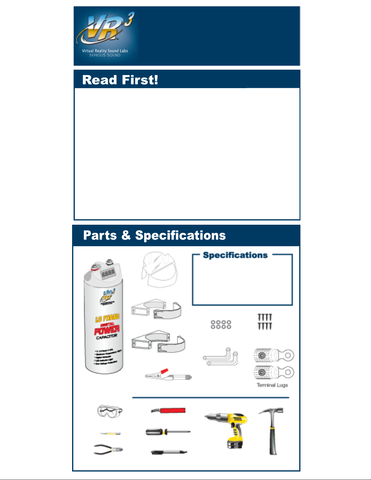
The VRPC1000 Power Cap provides a stable energy source for your amplifier.
8 Screws8 Washers
Upper Mounting Bracket
Lower Mounting Bracket
1.0 Farad Capacitor
4mm & 5mm
Hex Wrench
• 1.0 FARAD ±10%
• Maximum Voltage: 20 to 24V
• Maximum Temp: <90° C
• 4 Digit LED Voltage Display
For Optimum Performance: Position the Power Cap no more than 36 inches from amplifier.
Determine the desired location within
your vehicle as close to your audio
amplifier as possible. Attach mounting
brackets to the capacitor.
Make sure lower bracket is around the
bottom of the capacitor, and that the
capacitor is supported by the lip on
the bottom of the lower bracket. The
top mounting bracket.
Hold capacitor in place and mark the
holes as shown. See Fig. 1
With a hammer and center punch,
dimple the marks, to prevent the drill
bit from slipping.
Using an electric drill with a 1/16"
high-speed bit, drill the pilot holes
where dimpled with the center punch
for the mounting brackets.
Mount both bases of the brackets,
position the Power Cap inside the
mounting brackets, make sure the
bottom of the capacitor is supported.
Position the retaining brackets over
the Power Cap. Line up the screw
holes on all pieces. Insert and hand
tighten the provided screws with a
philips screwdriver to mount the
Power Cap firmly in place. See Fig. 2
Safety glasses should be worn at this time.
Safety glasses
Hammer
Drill w/1/16" bit
Philips Screwdriver
Wire Cutter Marker Pen
Center Punch
8-12 gauge wire
Tools Needed
Mounting
Chassis
Ground
Firewall Between
Engine & Vehicle
Compartment
12 Volt
Battery
Wiring Overview
Automotive audio equipment installations can be troublesome at times, even to the
most experienced of installation technicians. If you are not confident working with
electrical wiring, removing and reinstalling interior panels, carpeting, dashboards or
other components of your vehicle, please call us on our TOLL FREE help line
(800)445-1797 or e-mail us at customerservice@roadmaseterusa.com and our
in-house technical service team will answer your installation questions.
Cartridge Bulb with Clip
1 Clear Terminal Cover
Inline Fuse
(See Chart Below)
on Positive (+) Battery Cable
Inline Fuse Size
Amplifier Fuse Size
20 Amps
40 Amps
50 Amps
75 Amps
25-30 Amps
45-50 Amps
55-60 Amps
80-90 Amps
INLINE FUSE SIZES
This schematic shows you a basic view of how the Power Cap is wired in a single
amplifier configuration. For safety, it is highly recommended that you install an
Inline fuse. Select a fuse that is 5 to 10 Amps larger than the amplifier fuse.
Page 2

GIVE US A CALL, WE'LL HELP YOU INSTALL!
1-800-445-1797
For Information and Technical Assistance, Call Toll-Free in U.S.A. and Canada.
For Optimum Performance: Position the Power Cap no more than 36 inches from amplifier.
Determine the desired location within
your vehicle as close to your audio
amplifier as possible. Attach mounting
brackets to the capacitor.
Make sure lower bracket is around the
bottom of the capacitor, and that the
capacitor is supported by the lip on
the bottom of the lower bracket. The
top mounting bracket.
Hold capacitor in place and mark the
holes as shown. See Fig. 1
With a hammer and center punch,
dimple the marks, to prevent the drill
bit from slipping.
Using an electric drill with a 1/16"
high-speed bit, drill the pilot holes
where dimpled with the center punch
for the mounting brackets.
Mount both bases of the brackets,
position the Power Cap inside the
mounting brackets, make sure the
bottom of the capacitor is supported.
Position the retaining brackets over
the Power Cap. Line up the screw
holes on all pieces. Insert and hand
tighten the provided screws with a
philips screwdriver to mount the
Power Cap firmly in place. See Fig. 2
Safety glasses should be worn at this time.
Mark holes
with pen
Mounting
Ampli fier
Chassis
Ground
Cable
Chassis
Ground
Firewall Between
Engine & Vehicle
Compartment
Power Cap
Positive (+) Cable
to Amplifier
12 Volt
Battery
Wiring Overview
Strip a fingernail width of insulation from
the chassis ground wire and twist the
ends together. Insert the negative (-)
chassis ground wire into a lug, tighten
the set screw. Fig. 3
Take the remaining lug and insert the
end of the supplied cartridge light bulb,
and gently tighten the set screw. Fig. 4
Connect both lugs to the terminal
posts of the capacitor with the terminal
post screws. Make sure to maintain
polarity by connecting the chassis
ground lug to the negative terminal,
and the lug with the light bulb with clip
to the positive terminal. Fig. 5
Open the jaws of the clip and take the
positive wire from the battery and insert
it into the clip, let the jaws of the clip
close on the end of the wire. The bulb
will light brightly at first, and as become
dim as charging occurs. After about
twenty seconds, the blue LEDs and the
numbers on the digital voltage display
will light, and you will hear a beeping
sound. When the cartridge light goes out
the capacitor is charged. With the
positive lug still attached, remove the
light bulb. Fig. 6
Insert the positive wire from the amplifier,
and the positive wire from the battery,
into the positive lug and tighten the set
screw. Fig. 7
Connect the positive lug to the positive
terminal of the capacitor, secure the lug
tightly with the positive terminal post
screws. Fig. 8
Be advised that the digital voltage
display on the VRPC1000 power
capacitor will automatically turn OFF
after two minutes of operation at a stable
voltage. It will also turn back ON
whenever a change of more than 1.5
Volts occurs. It is normal for the digital
Automotive audio equipment installations can be troublesome at times, even to the
most experienced of installation technicians. If you are not confident working with
electrical wiring, removing and reinstalling interior panels, carpeting, dashboards or
other components of your vehicle, please call us on our TOLL FREE help line
(800)445-1797 or e-mail us at customerservice@roadmaseterusa.com and our
in-house technical service team will answer your installation questions.
Connecting the Terminal Lugs
Charging the Capacitor
VISIT OUR WEBSITE AT WWW.VR-3.COM
Fig.1
Fig.2
Inline Fuse
(See Chart Below)
on Positive (+) Battery Cable
Inline Fuse Size
Amplifier Fuse Size
20 Amps
40 Amps
50 Amps
75 Amps
25-30 Amps
45-50 Amps
55-60 Amps
80-90 Amps
INLINE FUSE SIZES
This schematic shows you a basic view of how the Power Cap is wired in a single
amplifier configuration. For safety, it is highly recommended that you install an
Inline fuse. Select a fuse that is 5 to 10 Amps larger than the amplifier fuse.
Page 3

GIVE US A CALL, WE'LL HELP YOU INSTALL!
1-800-445-1797
For Information and Technical Assistance, Call Toll-Free in U.S.A. and Canada.
VIRTUAL REALITY SOUND LABSTM products are designed and manufactured to provide a high level of trouble-free performance. VIRTUAL REALITY SOUND
LABSTM warrants, to the original purchaser, that its products are free from defects in material and workmanship for 30 days from the date of original purchase,
as part of our commitment to product excellence. VIRTUAL REALITY SOUND LABS
production methods of its existing products. Because it is impractical to publicize all changes in every product, we reserve the right to make such changes
without notice.
CONDITIONS OF WARRANTY:
If during the 30 day warranty period your new product is found to be defective, VIRTUAL REALITY SOUND LABS
product, without charge for parts or labor subject to the following conditions:
1. All repairs must be performed by VIRTUAL REALITY SOUND LABSTM and/or it’s affiliates in Eatontown, New Jersey.
2. The equipment must not have been altered or been damaged through negligence, accident, or improper operation.
3. The replacement of parts are exempted from this warranty when replacement is necessary due to normal wear and tear.
4. All warranty claims must be accompanied by a copy of the sales receipt or bill of sale.
5. Repair or replacement parts supplied by VIRTUAL REALITY SOUND LABS
TM
warranty.
6. In the case of car stereos, this warranty does not extend to the elimination of car static or motor noise; correction of antenna problems; costs incurred for
the removal or reinstallation of the product; damage to tapes, speakers, accessories or car electrical systems.
7. VIRTUAL REALITY SOUND LABSTM will not be responsible for any charge incurred for installation.
OWNER'S RESPONSIBILITIES:
VIRTUAL REALITY SOUND LABSTM will make every effort to provide warranty service within a reasonable period of time.
SHOULD YOU HAVE ANY QUESTIONS ABOUT SERVICE RECEIVED, OR IF YOU WOULD LIKE ASSISTANCE IN OBTAINING SERVICE, PLEASE CALL TOLL
FREE 1-800-445-1797, 8:30am - 4:30pm EST.
In order to provide you with the proper warranty service, we request that you adhere to the following procedure:
1. Include a copy of your sales receipt or bill of sale with your unit when it is returned for warranty service.
2. If it is necessary to return your product for service, please return it securely packed, preferably in the original shipping carton, and freight and insurance
prepaid to the following address: VIRTUAL REALITY SOUND LABSTM, Service Department, 41 James Way, Eatontown, New Jersey 07724.
3. Please include a detailed explanation of the problem you are having.
4. If your product is found by VIRTUAL REALITY SOUND LABSTM to have a defect in material or workmanship, within the warranty period, it will be repaired or
replaced at no charge and returned to you prepaid. Where permitted by Iaw VIRTUAL REALITY SOUND LABS
warranty. This warranty shall be the exclusive remedy of the purchaser.
VIRTUAL REALITY SOUND LABSTM makes no other warranty of any kind, expressed or implied; and all implied warranties, are hereby disclaimed by VIRTUAL
REALITY SOUND LABSTM and excluded from this warranty, VIRTUAL REALITY SOUND LABS
shall not be liable for any injury, loss or damage, incidental or consequential, arising out of the use or intended use of the product.
Strip a fingernail width of insulation from
the chassis ground wire and twist the
ends together. Insert the negative (-)
chassis ground wire into a lug, tighten
the set screw. Fig. 3
Take the remaining lug and insert the
end of the supplied cartridge light bulb,
and gently tighten the set screw. Fig. 4
Connect both lugs to the terminal
posts of the capacitor with the terminal
post screws. Make sure to maintain
polarity by connecting the chassis
ground lug to the negative terminal,
and the lug with the light bulb with clip
to the positive terminal. Fig. 5
Open the jaws of the clip and take the
positive wire from the battery and insert
it into the clip, let the jaws of the clip
close on the end of the wire. The bulb
will light brightly at first, and as become
dim as charging occurs. After about
twenty seconds, the blue LEDs and the
numbers on the digital voltage display
will light, and you will hear a beeping
sound. When the cartridge light goes out
the capacitor is charged. With the
positive lug still attached, remove the
light bulb. Fig. 6
Insert the positive wire from the amplifier,
and the positive wire from the battery,
into the positive lug and tighten the set
screw. Fig. 7
Connect the positive lug to the positive
terminal of the capacitor, secure the lug
tightly with the positive terminal post
screws. Fig. 8
Be advised that the digital voltage
display on the VRPC1000 power
capacitor will automatically turn OFF
after two minutes of operation at a stable
voltage. It will also turn back ON
whenever a change of more than 1.5
Volts occurs. It is normal for the digital
For Positive Lug
Wire From Positive
Battery Terminal
Wire From Positive
Amplifier Terminal
Set Screw
NEGATIVE LUG
Chassis Ground Wire
Set Screw
Connecting the Terminal Lugs
Light Bulb with Clip
Negative
REAR VIEW
POSITIVE LUG
Positive
Cartridge Bulb
Positive From Battery
Negative
Chassis
Ground
FRONT VIEW
LED Display
Negative
Chassis
Ground
Rear View
Positive
from
Amp & Battery
Charging the Capacitor
Why does the digital display on my capacitor go off after a few minutes?
The digital display and the blue LEDs will go off after approximately 2
minutes. This is normal operation. If you suspect the VRPC 1000 is defective
disconnect the capacitor from the battery positive terminal. The capacitor will
begin to discharge. When the voltage drops below 12 volts the display will
come on and the alarm chime will sound. Reconnect the VRPC 1000 to the
battery. After 2 minutes, the display and LEDs will go off again.
My headlights dim. Will the VRPC1000 Power Capacitor stop this?
Probably not entirely. Dimming headlights indicates that the audio system
you installed is overtaxing the alternator. The purpose of a Power Capacitor is
to provide the amplifier with extra power on demand so that it can faithfully
reproduce the input signal. Adding a separate battery for the audio system
might help, but in reality, a higher output alternator is required to keep
headlights from dimming.
Where should I mount this capacitor?
It should be mounted as close to your amplifier as possible, but not more
than 36" from the amplifier. The mounting brackets can be attached to
carpeted or metal surfaces.
Can I connect the VRPC1000 ground to the same chassis ground as my
amplifier?
Yes, of course. If the ground connection is adequate for the amplifier, it is a
good place to connect the VRPC1000 negative terminal.
I have two amplifiers totaling 1200 Watts. Will one VRPC1000 work?
The VRPC1000 Power Capacitor is rated to handle 1000 Watts of amplifier. If
your combined amplifier power is greater than 1000 Watts, use two
VRPC1000's wired positive (+) to positive (+) and negative (-) to negative (-),
or connect one across each of the amplifier's power terminals.
VISIT OUR WEBSITE AT WWW.VR-3.COM
Fo r a vid eo tut ori al on ch argin g t he
VRPC1000 go to our website and on
the products menu chose VRPC100.
Once on the VRPC100 page, find the
link for vid eo t utorial and c li ck on it,
Fig. 3
Fig. 4
Fig. 5
Fig. 6
Fig. 7
Fig. 8
Limited Warranty
©2005 Virtual Reality Sound LabsTM All designs, logos and images are the exclusive property of Virtual Reality Sound Labs
Page 4

VIRTUAL REALITY SOUND LABSTM products are designed and manufactured to provide a high level of trouble-free performance. VIRTUAL REALITY SOUND
LABSTM warrants, to the original purchaser, that its products are free from defects in material and workmanship for 30 days from the date of original purchase,
as part of our commitment to product excellence. VIRTUAL REALITY SOUND LABSTM and/or it’s affiliates routinely improves the designs, materials or
production methods of its existing products. Because it is impractical to publicize all changes in every product, we reserve the right to make such changes
without notice.
CONDITIONS OF WARRANTY:
If during the 30 day warranty period your new product is found to be defective, VIRTUAL REALITY SOUND LABSTM will repair such defect, or replace the
product, without charge for parts or labor subject to the following conditions:
1. All repairs must be performed by VIRTUAL REALITY SOUND LABSTM and/or it’s affiliates in Eatontown, New Jersey.
2. The equipment must not have been altered or been damaged through negligence, accident, or improper operation.
3. The replacement of parts are exempted from this warranty when replacement is necessary due to normal wear and tear.
4. All warranty claims must be accompanied by a copy of the sales receipt or bill of sale.
5. Repair or replacement parts supplied by VIRTUAL REALITY SOUND LABSTM under this warranty are protected only for the unexpired portion of the original
warranty.
6. In the case of car stereos, this warranty does not extend to the elimination of car static or motor noise; correction of antenna problems; costs incurred for
the removal or reinstallation of the product; damage to tapes, speakers, accessories or car electrical systems.
7. VIRTUAL REALITY SOUND LABSTM will not be responsible for any charge incurred for installation.
OWNER'S RESPONSIBILITIES:
VIRTUAL REALITY SOUND LABSTM will make every effort to provide warranty service within a reasonable period of time.
SHOULD YOU HAVE ANY QUESTIONS ABOUT SERVICE RECEIVED, OR IF YOU WOULD LIKE ASSISTANCE IN OBTAINING SERVICE, PLEASE CALL TOLL
FREE 1-800-445-1797, 8:30am - 4:30pm EST.
In order to provide you with the proper warranty service, we request that you adhere to the following procedure:
1. Include a copy of your sales receipt or bill of sale with your unit when it is returned for warranty service.
2. If it is necessary to return your product for service, please return it securely packed, preferably in the original shipping carton, and freight and insurance
prepaid to the following address: VIRTUAL REALITY SOUND LABSTM, Service Department, 41 James Way, Eatontown, New Jersey 07724.
3. Please include a detailed explanation of the problem you are having.
4. If your product is found by VIRTUAL REALITY SOUND LABSTM to have a defect in material or workmanship, within the warranty period, it will be repaired or
replaced at no charge and returned to you prepaid. Where permitted by Iaw VIRTUAL REALITY SOUND LABSTMliability shall be limited to that set forth in this
warranty. This warranty shall be the exclusive remedy of the purchaser.
VIRTUAL REALITY SOUND LABSTM makes no other warranty of any kind, expressed or implied; and all implied warranties, are hereby disclaimed by VIRTUAL
REALITY SOUND LABSTM and excluded from this warranty, VIRTUAL REALITY SOUND LABSTM and/or it’s affiliates, the manufacturer, distributor and seller
shall not be liable for any injury, loss or damage, incidental or consequential, arising out of the use or intended use of the product.
Why does the digital display on my capacitor go off after a few minutes?
The digital display and the blue LEDs will go off after approximately 2
minutes. This is normal operation. If you suspect the VRPC 1000 is defective
disconnect the capacitor from the battery positive terminal. The capacitor will
begin to discharge. When the voltage drops below 12 volts the display will
come on and the alarm chime will sound. Reconnect the VRPC 1000 to the
battery. After 2 minutes, the display and LEDs will go off again.
My headlights dim. Will the VRPC1000 Power Capacitor stop this?
Probably not entirely. Dimming headlights indicates that the audio system
you installed is overtaxing the alternator. The purpose of a Power Capacitor is
to provide the amplifier with extra power on demand so that it can faithfully
reproduce the input signal. Adding a separate battery for the audio system
might help, but in reality, a higher output alternator is required to keep
headlights from dimming.
Where should I mount this capacitor?
It should be mounted as close to your amplifier as possible, but not more
than 36" from the amplifier. The mounting brackets can be attached to
carpeted or metal surfaces.
Can I connect the VRPC1000 ground to the same chassis ground as my
amplifier?
Yes, of course. If the ground connection is adequate for the amplifier, it is a
good place to connect the VRPC1000 negative terminal.
I have two amplifiers totaling 1200 Watts. Will one VRPC1000 work?
The VRPC1000 Power Capacitor is rated to handle 1000 Watts of amplifier. If
your combined amplifier power is greater than 1000 Watts, use two
VRPC1000's wired positive (+) to positive (+) and negative (-) to negative (-),
or connect one across each of the amplifier's power terminals.
Limited Warranty
©2005 Virtual Reality Sound LabsTM All designs, logos and images are the exclusive property of Virtual Reality Sound LabsTM and/or it’s affiliates.
All rights reserved. Ver 1.1 033005 Printed in China 00000
 Loading...