

Page 1
Instructions / Owner’s Manual
VRCD300M
CD CD/R
MP3
WMA
CD/RW
ID3
AUX In
AM/FM Stereo
CD/CD-R/ CD-RW/MP3/WMA PLAYER
180
WATTS*
MARINE/OFF-ROAD
APPROVED
1
Page 2

Page 3

Welcome
Dear Customer,
CONGRATULATIONS. The VRCD300M when used as described, will give you years of
dependable service in your boat, car, truck, RV, or mini-van. We have taken exacting
measures in quality control to ensure that your product arrives in top condition and will
perform to your satisfaction.
In the rare event that your VRCD300M is missing an item, contains a damaged part,
does not perform as specied, requires warranty service, or you have an installation
problem, DO NOT RETURN THIS PRODUCT TO THE STORE. PLEASE CALL OUR
TOLL FREE NUMBER FROM THE U.S.A. AND CANADA 1-800-445-1797 and ask to
speak with a member of our technical service team; or submit your questions to
technicalsupport@vr-3.com and a member of our technical service team will respond by
email to your questions.
Our in-house technical service team will expedite delivery of your part, advise you on
installation, or help troubleshoot a problem with you. If your product needs warranty
service, our technical service team representative will help you obtain the fastest remedy possible under the warranty.
Table Of Contents
Contents .......................................................................................................... 2
Precautions ..................................................................................................... 3
Care of Discs ................................................................................................... 4
Before You Install ............................................................................................ 5
Tools Needed to Install .................................................................................. .5
Parts Included ................................................................................................. 5
Marine Enclosure Installation. ......................................................................... 6
Vehicle Installation ....................................................................................... 7-9
Wiring Diagram ...............................................................................................10
Position of Controls........................................................................................ 11
Remote Control ..............................................................................................12
Basic Operation .............................................................................................13
Digital Tuner Operation ..................................................................................14
File / Folder Search Function .........................................................................15
Specications .................................................................................................16
Warranty .........................................................................................................17
2
Page 4

PRECAUTIONS
Please read these important precautions BEFORE
attempting to install this unit. Driving a vehicle while
operating this head unit may violate motor vehicle laws,
and may result in serious injury, property damage, or
death!
• Disconnect the vehicle’s negative battery terminal before starting installation.
Consult the vehicle’s owner’s manual
for proper instruction.
• The unit is designed for a 12 Volt DC
negative ground operation system only.
Before installing the unit, make sure
your vehicle is a 12 Volt DC negative
ground electrical system.
•
Mark the polarity of the existing speaker
wires before disconnecting the old head
unit.
•
Be sure to connect the color coded
leads according to the wiring diagram.
Incorrect connections may damage the
unit, cause the unit to malfunction or
cause damage the vehicle's electrical
system.
• Make sure all the connections are
completely correct before final in-dash
installation of your unit.
• When extending the ignition, memory
backup or the ground cable, use
0.75mm diameter (AWG18) or heavier
automotive grade cable to avoid wire
deterioration or damage to the wire
coating.
•
To prevent short circuit, never put or
leave any metallic object inside the unit.
If you smell or see smoke, turn off the
power immediately and consult your
dealer.
•
Insert the unit until it is firmly locked into
mounting sleeve, otherwise it may fall out.
• Be careful not to drop or shock the unit,
it may break or crack because it contains glass parts.
• The unit is only designed for use with
4 speakers and a sub-woofer. Do not
combine speaker output wires for
use with 2 speakers. Do not ground
negative speaker leads to the chassis
ground.
• Do not open the top or bottom cover.
Modifying the unit will void the warranty
and may damage the unit, cause the
unit to malfunction or cause damage
the vehicle's electrical system.
• Parking in direct sunlight for several
hours will cause higher temperatures
inside the vehicle. Do not operate in
extremely high or low temperatures.
The temperature inside the vehicle
should be between 32º F (0º C) and
100º F (37º C) before turning on your
unit. Cool down the vehicle before
operating the unit.
• The faceplate is a precision piece of
equipment that contains sensitive electronic components. Do not subject it to
excessive shock.
• When replacing the fuse(s), the replace
ment must be of the same amperage as
shown on the fuse holder.
• Do not block this unit’s vents or heater
panels. Blocking them will cause excessive heat to build up inside the unit and
may result in fire.
• After completing the installation and
before operating the unit, reconnect the
battery according to the manufacturer’s
instructions. Turn the unit ON, then
press the reset (RES) button with a
pointed object, such as a ball-point pen
to set the unit to its initial status.
• Do not touch the terminals of the face
plate or of the unit.
• If you have difficulty installing this unit
in your vehicle, or if you are missing
parts, contact customerservice@vr-
3.com or call us toll-free at 1-800-4451797
-
-
3
Page 5

Care of Discs
• Do not operate the player with scratched, bent or broken discs. discs. When a disc
does not load properly, do not force it into the disc loader.
• Never insert any foreign objects such as coins, pins, credit or ATM cards into the disc
loader, this will damage the loading mechanism or cause it short circuit.
• Only use 12 cm CDs.
• Do not use CDs with labels or stickers
• Handle the disc by its edge to keep the disc
clean. Do not touch the disc’s surface.
attached. The label may leave a sticky residue when it begins to peel.
• Clean the discs with an optional cleaning
• Do not use a CD with paste or ink residue
on it.
IMPORTANT!
•
Remove the two transport screws from the top of the unit before installing.
• Before nal installation of the unit, connect the wiring temporarily, making sure the unit
and the system work properly.
• Use only the parts included with unit to ensure proper installation. The use of unauthor
ized parts can cause malfunctions.
• Consult with your vehicle’s nearest dealership if installation requires the drilling of holes
or other modications of the vehicle.
• Install the unit where it does not get in the driver’s way and cannot injure the passenger
if there is a sudden stop, like an emergency stop.
• The laser will be damaged if it overheats, so don’t install the unit anywhere hot--for
instance, near a heater outlet.
• If installation angle exceeds 30 degrees from horizontal, the unit might not give its optimum performance.
cloth. Wipe each disc from the center out.
4
-
Page 6
Before You Install
Audio equipment installations can be challenging at times, even to the most experi-
enced of installation technicians. If you are not condent working with electrical wiring,
removing and reinstalling interior panels, carpeting, instrument panels or other components of your boat or vehicle, please call our toll-free help line 1-800-445-1797 and
our in-house technical service team will answer your installation questions. Contact
the vehicle's manufacturer for vehicle specic instructions, or consider having the
VRCD300M professionally installed.
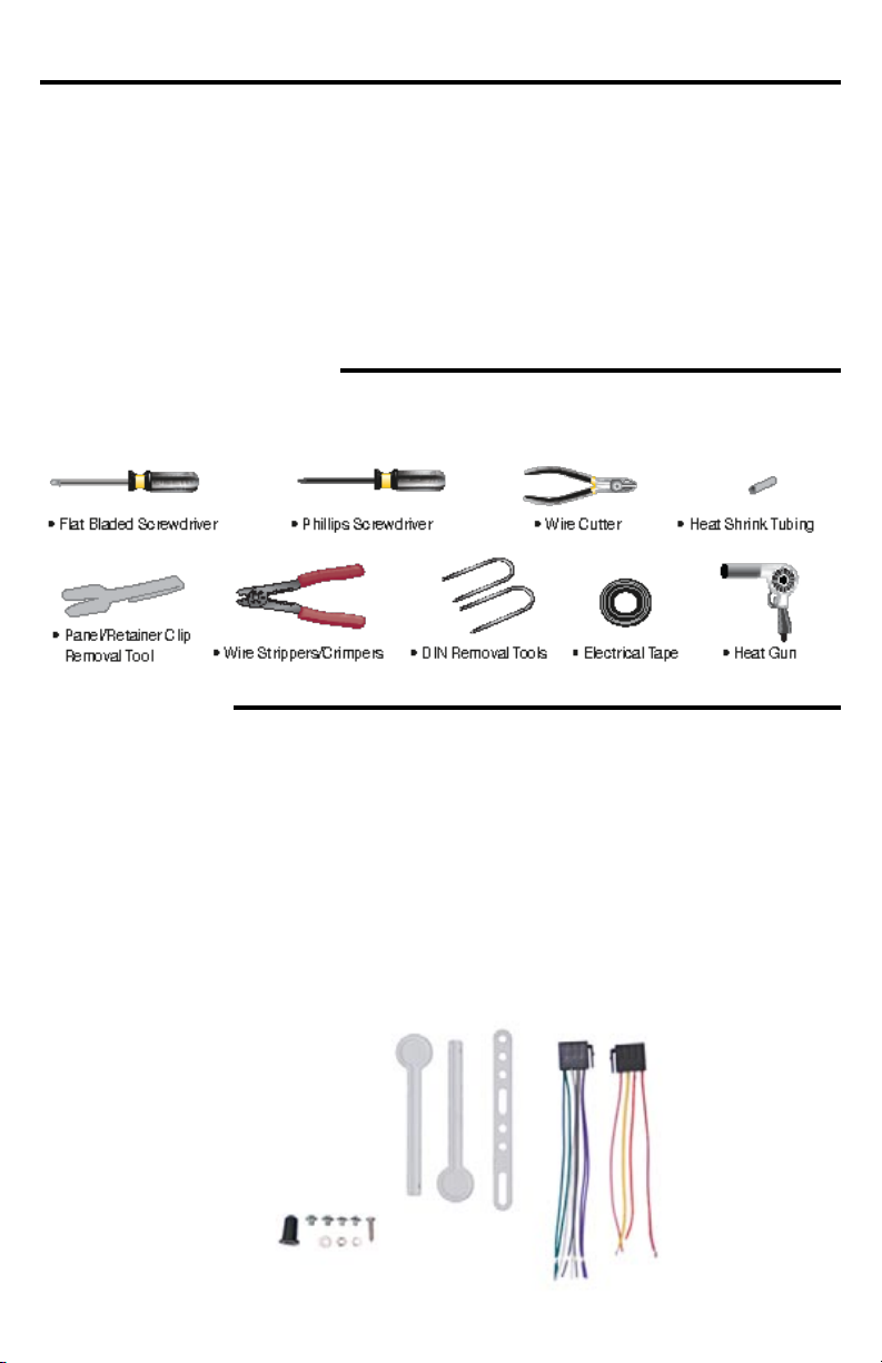
Tools Needed to Install
Below are the basic tools needed for most installations. Depending on the vehicle you
may need other tools to complete the installation. Tools Not Included.
Parts Included
Package will include the following parts & accessories for installation and operation of the unit.
1 - Marine Mounting Enclosure (not
shown)
1 - Head Unit
1 - Remote Control
2 - Removal Keys
1 - Metal Mounting Strap
1 - Rubber
1 - Sheet Metal Screw(B5x20)
4 - Screws (M5x6)
1 - Washer
1 - Lock Washer
1 - Hex Nut
1 - Power Cable Harness
1 - Speaker Cable Harness
1 - Mounting Sleeve (not shown)
5
Page 7

Marine Enclosure Installation
IMPORTANT!
BEFORE THE FINAL INSTALLATION OF THE HEAD UNIT, CONNECT THE WIRING
TEMPORARILY, MAKING SURE THE UNIT AND THE SYSTEM WORK PROPERLY.
The Marine Enclosure can be mounted two ways. On top of or below the mounting surface.
Bottom MountTop Mount
1. Choose a place to mount the marine enclosure, and place the enclosure with the
bracket attached on the chosen mounting area. Make sure the unit does not interfere
with safe operation of the boat.
2. Remove the mounting bracket from the marine enclosure.
3. Place the bracket on the mounting area and use a pencil to mark where the pilot
holes for the screws will be drilled. Before drilling the pilot holes CONNECT THE WIR-
ING TEMPORARILY TO MAKE SURE THE UNIT AND THE SYSTEM WORK PROPERLY.
4. Check the area behind the mounting surface for any electrical, fuel or other marine
system components that may be damaged when drilling pilot holes for the mounting
screws
5. Drill pilot holes with a drill bit that has a smaller diameter than the mounting screws.
6. Align the holes of mounting bracket with the pilot holes, then attach the bracket with
the screws.
7. Mount the enclosure on the bracket.
8. Permanently connect the wires according to the wiring diagram.
Unit in Marine Enclosure
6
Page 8

Vehicle Installation
Remove the Unit from the Marine Enclosure
1. Loosen the screws to remove the covers.
2. Remove the bolt.
3. Detach the main unit from the waterproof housing unit.
Remove the Old Unit from the Dashboard
A. Remove the outer trim frame(not shown).
B. Insert the keys supplied with the old unit into both sides of the old unit as
shown in figure below until they click. Push keys apart and pull to remove the
old unit from the dashboard.
DO NOT DISCONNECT WIRES AT THIS TIME!
Mark Polarity of the Speaker Wires
Marking the polarity of the speaker wires will make it easier to connect the existing
speakers to the Head Unit.
Consult wiring diagram of existing head unit before disconnecting any wires. If a
wiring diagram is not available contact the manufacturer.
A.
While the old unit is playing, discon-
nect the wires from one speaker.
B. Take a length of masking tape and
fold it around the wire so it forms a
flag.
C. On the masking tape mark the po-
larity of the speaker wires (+ & - ), as
well as left or right, and front or rear.
D. Double check that you marked the
first speaker correctly by checking
that the speaker wires are the same
at the head unit.
E. Repeat this procedure for all of the
speakers.
F. Mark the power, ground, and any
other wires also
7
.
Page 9

Vehicle Installation
DIN FRONT-MOUNT (Method A)
NOTE:
Unit should be installed horizontally or less than a 30° angle.
1. Insert Half Sleeve into dashboard.
2. Bend mount tabs outwards to secure it.
3. Insert the unit into the Half Sleeve until you hear a click sound. If necessary,
attach the mounting strap to the rear of the unit, then attach it with the sup-
plied nut as in g. 2.
4. Place Trim Ring over the unit and installation is completed
(Some vehicles may not need Trim Ring)
Un-installation (Figure 3)
1. Remove Trim Ring and
insert Release Keys into
left and right side-end
holes as shown in gure
and pull the unit out of the
dash-board.
Remove the two transport screws from
the top of the unit before installing.
8
Page 10

Vehicle Installation
DIN REAR-MOUNT (Method B)
Installation using the screw holes on both sides of the unit.
Note: The mounting sleeve, outer trim ring, and the mounting strap are not
used for this method of installation.
1. Screw holes on the side of the unit.
2. Screws. Use either truss screws (5 x 8mm) or ush surface screws (4 x 8mm),
depending on the shape of the screw holes in the bracket.
3. Vehicle’s Factory Mounting Bracket
4. Dashboard or Console
5. Hook (Remove this part)
9
Page 11

Wiring Diagram
• Before starting the installation, disconnect the negative battery cable
from the battery’s negative terminal.
• Beforenal installationofthe unit,temporarily connect thewiring to
ensure the unit operates correctly.
NOTES
10
Page 12

Position of Controls
1 2 3 4 5 6
20
2122
1. Power ON/OFF
2. Volume +
3. AS/PS
4. Mono/Stereo
5. Loud
6. Liquid Crystal Display
7. Local/Distant
8. Disp
9. Tune/Track Up
10. Faceplate Release
11. Mute
12. Tune/Track Down
13. Band
14. #6 / +10
9
7
1516171819
15. #5 / -10
16. #4 / Random
17. #3 / Intro
18. #2 / Repeat
19. #1 / Pause
20. SEL
21. Volume -
22. Mode
23. Disc Slot
24. Eject Disc
25. Reset Button
8
12
1314
10
11
23
Unit with Faceplate Lowered
24
11
25
Page 13

Remote Control
1. Power
2. Mode/SW
3. Mute
4.
Number Buttons/Presets
(1/Play/Pause, 2/Repeat, 3/Intro, 4/ Random, 5/-10 Tracks
6/+10 Tracks)
5. Previous/Fast Reverse
6. Band
7. Volume Down
8. SEL
Use and Care of the Remote
Aim the Infra Red LED of the remote control at the front panel of the unit to operate.
Precautions:
• Dispose of used batteries properly. Follow your local recyling laws.
• Using batteries improperly can cause them to explode.
• Keep batteries out of the reach of children.
• Should the battery be swallowed, immediately consult a doctor.
• Use one CR2025(3V) lithium battery only.
• Remove the battery if the remote control is not to be used for a month or longer.
• Do not short-circuit or disassemble.
• Do not drop the remote control, it may become jammed under the brake or accelerator pedals.
9. Dis
10. Loud
11. Loc
12. Stereo/Mono
13. AS/PS
14. Next/Fast Forward
15. Volume Up
Changing the Battery
Turn the remote over,
then slide the battery
holder out of the remote.
Insert battery into battery
holder with positive side
of the battery facing up.
12
Insert battery holder
into the remote control
until it clicks.
Page 14

Basic Operation
Front Panel
Press OPEN button on the front panel to
flip down the front panel.
Reset the unit
Operating the unit for the first time or after
replacing the car battery, you must reset
the unit.
Press OPEN button on the panel to open
the panel and press RESET button to
restore the unit to its original factory settings.
Power ON/OFF
Press any button (except OPEN) to turn on
the unit. Press the PWR button on front
panel or press the PWR button on the
remote control to switch the unit OFF.
Note: After the unit is off, the volume level
and radio current settings will be memorized, and when you turn the unit on it will
resume the stored status you previously
set.
Volume control
Press VOL +/- buttons to adjust the volume level.
Turning the sound off
Press MUTE button to turn the sound off.
Press it again to turn the sound on.
Sound Characteristics
Short press SEL button to select the audio
and contrast settings: VOLUME > BASS >
TREBLE > BALANCE > FADER. Press the
VOL +/- button to adjust each setting.
Note:
• If the unit is turned off, all the settings
of each mode will be saved.
• If the battery is disconnected or the
unit is reset, all the settings will return
to factory default settings.
Setting other features
Press SEL button and hold for 2 seconds,
short press and repeat them again to
select these settings: DSP OFF>BEEP
2 ND>12 HOUR. Press VOL+/- button to
adjust each setting.
DSP – Press Vol+/- to choose intended
sound effect in the sequence: OFF =>
FLAT =>CLASSIC => POP => ROCK.
12/24 HOUR: Choose 12 HOUR mode or
24 HOUR mode for clock.
Mode setting
Press MODE button TUNER > (* CD) >
AUX (rear) > TUNER
(* available only if there is media device
in disc)
Display
Press DIS button to see current tuning
information and time.
In Radio mode:
CT (Clock/Time) -> Exit Display
In CD mode, except the above menu, it will
also show ID3 information if the file has
ID3.
Adjust Clock/Time: Press DIS button once
to show time first, then press and hold this
button for about 3 seconds to enter time
adjusting mode, you can see time blink,
then press T-UP button to adjust hour
and press T-DN button to adjust minute,
and finally press DIS button once again to
confirm the adjustment.
Sub Woofer
Long press MODE button to enable or disable SUB-Woofer.
AUX IN (Back)
Intended to receive audio signals by connecting to external media player.
13
Page 15

Digital Tuner Operation
Band selection
Press MODE button to select TUNER.
Press BAND to select: FM1, FM2, FM3,
MW1 (AM1), and MW2 (AM2).
ST/MO
In FM mode, press ST/MO button on
remote control to select stereo or mono
sound reception.
Manual/Automatic tuning
Manual Tuning: To nd a station, select a
band rst, then press and hold T-DN/T-UP
buttons until MANUAL appears on the display, then press these buttons repeatedly
to search a station upward or downward.
Automatic Tuning: To nd a station, select
a band rst, then press T-DN/T-UP but-
tons, the automatic downward/upward
search will start. It will play when a station
is found.
Programming preset stations
You can store up to a total of 30 radio
stations in the memory (18 FM, 12 AM),
manually or automatically.
To store a station:
1. Select a band (if needed)
2. Select a station by pressing T-DN/T-UP
buttons.
3. Hold a Preset button (1-6), where you
want to store the station for at least 2
seconds.
To recall a station:
1. Select a band (if needed)
2. Press a Preset button (1-6) briey to
recall the stored station.
Auto memory store
Select a band, press AS/PS (Auto Scan/
Preset Scan) button on the panel and
hold for 2 seconds to enter auto store
mode. The radio will automatically store 6
stations to the 6 preset memories of the
current band. To stop auto store, press
AS/PS button again.
Note: During auto station preset, the unit
will search and store stations with the
strong signal rst, and then weaker signal
stations until the memories are full.
Preset scan
Select a band, press AS/PS button to
scan all preset stations in the memories of
the current band, each preset scan for 5
seconds. To stop preset scans, press the
button again.
Loading/Ejecting a disc
Turn the power on. Press OPEN button
and insert the disc into disc slot with the
printed side facing up. Press EJECT button to eject the disc.
Play/Pause
The unit will automatically play from the
rst sound track recorded on a disc. To
ensure good system performance, wait
until the unit nishes reading the disc /device information before proceeding. Press
PAUSE button to pause playback, press it
again to resume playback.
Playing the previous/next track
During playback press PREVIOUS button
to play the previous track. Press NEXT
button to play the next track.
Scanning forward and backward
Press and hold / buttons to select
fast backward/forward playing.
Note: When fast backward/forward playback reaches the previous or next track,
the unit will resume normal playback.
T-UP / T-DN
Press 5/, 6/ + 10 buttons to advance 10
tracks backward or forward.
Repeat playback
Press RPT button to play track repeatedly,
press again to cancel.
Note: After nishing playing all tracks or all
folders of CD/MP3/WMA, the unit restarts
playing all tracks or all folders automatically.
Intro
Press 1/INT button to activate INTRO
function which will play the beginning of
every track for 10 seconds.
14
Page 16

File & Folder Search
Random
In disc mode press 4/RDM button to
activate random playing mode, press one
more time to return to normal playing.
Searching For Files
This head unit can search for les saved
on a CD, CD/R, CD/RW Disc.
NOTE: Devices connected to the Auxiliary
Input can not be searched.
File / Folder Search Function
In CD mode, press AS/PS button to enter
search mode.
Below is toggle sequence of search mode.
File Number Search > File Name Search >
Folder Search > Exit search mode
Note: For commercial CD disc, you can
only search by le number.
Search for File by Number
1. Press AS/PS button to enter le number
search
2. “MP3 T ” is displayed and the
blinks to show the unit is ready to accept
a le number to search for.
3. Press V+ / V- buttons on remote control
to input a digit from 0 to 9 of the track you
want to listen to.
4. Press the SEL button on the remote
control to move to the next digit. After
completing input, press BAND/ENT button
to play.
Search for File by Name
1. Press AS/PS button until an asterisk
blinks on left side of LCD.
2. Press the VOL +/- buttons on the remote control to input letters (from A to Z)
or a numbers (from 0 to 9) of the le you
want to listen to.
3. Press the SEL button on the faceplate
or remote control to change to the next
character.
4. After completing input, press the
BAND/ENT button to play.
If there is no le found, the unit will return
to initial input ready mode automatically.
Search for Folder
1. To start folder search, press the AS/PS
button 3 times. The word “ROOT” will be
displayed on LCD, then the name of the
first folder will be displayed.
2. Press VOL+ / VOL - buttons on remote
control to change the folder.
3. Press the Band button to select the
displayed Folder.
15
Page 17

Specifications
ELECTRIC
Power Supply ............................................................................................... DC 11 ~ 16 Volt
Current Consumption ..................................................................................... < 10 Ampere
Load Impedance ...................................................................................................4 - 8 Ohm
Dimensions .....................................................................178mm W x 165mm D x 50mm H
Maximum Power Output ................................................................................. 4 x 40 Watts
RMS Output ...................................................................................................... 4 x 19 Watts
FM TUNER
Frequency Range ...................................................................................... 87.5 ~ 107.9 MHZ
Usable Sensitivity .................................................................................................... 8 dBuV
Stereo Separation ....................................................................................................... 28 dB
AM (MW) TUNER
Frequency Range .........................................................................................530 ~ 1710 KHz
Usable Sensitivity ................................................................................................... 30 dBuV
CD PLAYER
Distortion THD .......................................................................................................... < 0.5%
Signal-to-Noise Ratio ................................................................................................. 60 dB
Frequency Range ........................................................................................... 20Hz - 20KHz
PANEL SYSTEM
Flip down front panel, ISO mount, LCD display
PLAYBACK
Decoding ....................... MP3, WMA playback with ID3 Tag display, file and folder search
Supports ............................................................................................... CD, CD-R, CD-RW
TUNER
AM/FM Receiver with 30(FM18, AM12) station memory, automatic & manual station
memory, preset scan, automatic / manual tuning
AUDIO
Amplifier .......................................................................................................... 4x40W (Max)
Auxilary Input ................................................................................. 2CH Stereo RCA Jacks
16
Page 18

Limited Warranty
VIRTUAL REALITY VIDEO LABS® products are designed and manufactured to provide a high level of
trouble-free performance. VIRTUAL REALITY VIDEO LABS warrants, to the original purchaser, that
its products are free from defects in material and workmanship for 30 days from the date of original
purchase. As part of our commitment to product excellence, VIRTUAL REALITY VIDEO LABS and/or
its afliates routinely improve the designs, materials or production methods of its existing products.
Because it is impractical to publicize all changes in every product, we reserve the right to make such
changes without notice.
CONDITIONS OF WARRANTY:
If during the 30 day warranty period your new product is found to be defective, VIRTUAL REALITY
VIDEO LABS will repair such defect, or replace the product, without charge for parts or labor subject
to the following conditions:
1. All repairs must be performed by VIRTUAL REALITY VIDEO LABS and/or its afliates in Eatontown,
New Jersey.
2. The equipment must not have been altered or been damaged through negligence, accident, or
improper operation.
3. The replacement of parts are exempted from this warranty when replacement is necessary due to
normal wear and tear.
4. All warranty claims must be accompanied by a copy of the sales receipt or bill of sale.
5.
Repair or replacement parts supplied by VIRTUAL REALITY VIDEO LABS under this warranty are protected
only for the unexpired portion of the original warranty.
6. In the case of car stereos, this warranty does not extend to the elimination of car static or motor
noise; correction of antenna problems; costs incurred for the removal or reinstallation of the product;
damage to tapes, speakers, accessories or car electrical systems.
7. VIRTUAL REALITY VIDEO LABS will not be responsible for any charge incurred for installation.
OWNER’S RESPONSIBILITIES:
VIRTUAL REALITY VIDEO LABS will make every effort to provide warranty service within a reasonable
period of time.
SHOULD YOU HAVE ANY QUESTIONS ABOUT SERVICE RECEIVED, OR IF YOU WOULD LIKE ASSISTANCE IN OBTAINING SERVICE, PLEASE CALL TOLL FREE 1-800-445-1797, 8:30am - 4:30pm
EST.
In order to provide you with the proper warranty service, we request that you adhere to the following
procedure:
1. Include a copy of your sales receipt or bill of sale with your unit when it is returned for warranty
service.
2. If it is necessary to return your product for service, please return it securely packed, preferably in the
original shipping carton, and freight and insurance prepaid to the following address: VIRTUAL REALITY VIDEO LABS, Service Department, 41 James Way, Eatontown, New Jersey 07724.
3. Please include a detailed explanation of the problem you are having.
4. If your product is found by VIRTUAL REALITY VIDEO LABS to have a defect in material or work-
manship, within the warranty period, it will be repaired or replaced at no charge and returned to you
prepaid. Where permitted by Iaw VIRTUAL REALITY VIDEO LABS® liability shall be limited to that set
forth in this warranty. This warranty shall be the exclusive remedy of the purchaser.
VIRTUAL REALITY SOUND LABS® makes no other warranty of any kind, expressed or implied; and
all implied warranties, are hereby disclaimed by VIRTUAL REALITY VIDEO LABS® and excluded from
this warranty, VIRTUAL REALITY VIDEO LABS® and/or its afliates, the manufacturer, distributor and
seller shall not be liable for any injury, loss or damage, incidental or consequential, arising out of the
use or intended use of the product.
Page 19

Page 20

©2009 Intellectual Solutions Inc., All Rights Reserved, All de signs, logos and images are the exclusive property of
Intelle ctual Solutions Inc. and/or its afliates. U.S. and Foreign Patents Pending. 072009 Printed in China 06055
 Loading...