

Page 1
VRCD220S
CD/MP3/WMA Player,
AM/FM Stereo Receiver with RDS,
Auxiliary Input and Detachable Face
VRCD220S English PROOF Manual.indd 1VRCD220S English PROOF Manual.indd 1 10/15/08 11:34:09 AM10/15/08 11:34:09 AM
Page 2

Welcome!
Dear Customer,
CONGRATULATIONS. The VRCD220S CD/MP3/WMA Player, AM/FM Stereo
Receiver with RDS, Auxiliary Input, Detachable Face and Speaker Kit when
used as described, will give you years of dependable service in your car,
truck, RV, or mini-van. We have taken numerous measures in quality control to ensure that your product arrives in top condition and will perform
to your satisfaction. In the rare event that your VRCD220S CD/MP3/WMA
Player, AM/FM Stereo Receiver with RDS, Auxiliary Input, Detachable Face
and Speaker Kit contains a damaged or missing item, does not perform as
specified, requires warranty service, or you have an installation problem, DO
NOT RE
FREE NUMBER FROM THE U.S.A. AND CANADA 1-800-445-1797 and ask
to speak with a member of our technical service team; or submit your questions by e-mail to customerservice@vr-3.com and a member of our technical
service team will respond by e-mail to your questions. Our in-house technical
service team will expedite delivery of your part, advise you on installation, or
help troubleshoot a problem with you. If your product needs warranty service, our technical service team representative will help you obtain the fastest
remedy possible under the warranty.
TURN THIS PRODUCT TO THE STORE. PLEASE CALL OUR TOLL
Contents
Precautions ..................................................................................................... 2
Notes on Installation ....................................................................................... 3
Before You Install ............................................................................................ 4
Installation (DIN Front Mount) ......................................................................... 5
Installation (Vehicle’s Brackets) ...................................................................... 6
Wiring Connections ......................................................................................... 7
Location of Controls........................................................................................ 8
Basic Operation .............................................................................................. 9
Radio Operation .............................................................................................10
RDS Operation ..........................................................................................10-11
CD Operation .................................................................................................12
AUX IN, RCA Out ............................................................................................14
Maintena nce ...................................................................................................14
Simple Troubleshooting Guide ......................................................................15
Specifi cations .................................................................................................15
Warranty .........................................................................................................16
VRCD220S English PROOF Manual.indd 2VRCD220S English PROOF Manual.indd 2 10/15/08 11:34:12 AM10/15/08 11:34:12 AM
Page 3
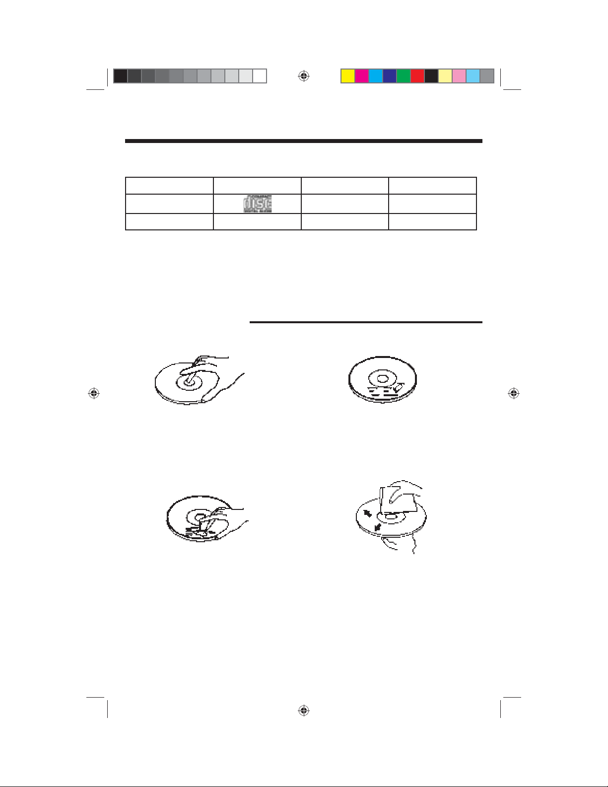
Precautions
This unit will only play the following discs.
Type of disc Label on the Disc Recorded Material Size of Disc
CD
Audio only 12 cm
MP3/WMA N/A
• Do not attempt to modify the unit.
• Modifying the unit will void the warranty.
Stop the vehicle before carrying out any oper-
•
ation that could interfere with your driving.
Care of Discs
• Handle the disc by its edge to keep the disc
clean. Do not touch the disc’s surface.
Audio only 12 cm
• Do not operate in extremely high or low temperatures. The temperature inside the vehicle
should be between 32º F (0º C) and 100º F
(37º C) before turning on your unit.
• Do not use CDs with labels or stickers
attached. The label may leave a sticky residue when it begins to peel.
• Do not use a CD with paste or ink residue
on it.
VRCD220S English PROOF Manual.indd 3VRCD220S English PROOF Manual.indd 3 10/15/08 11:34:12 AM10/15/08 11:34:12 AM
• Clean the discs with an optional cleaning
cloth. Wipe each disc from the center out.
2
Page 4
Notes on Installation
• Disconnect negative battery terminal before starting installation. Consult the vehicle’s
owner’s manual for proper instruction.
• The unit is designed for a 12 Volt DC negative ground operation system only. Before
installing the unit, make sure your vehicle is a 12 Volt DC negative ground system.
• Mark the polarity of the existing speaker wires before disconnecting the old unit.
• Be sure to connect the color coded leads according to the diagram. Incorrect connections may cause the unit to malfunction or damage the vehicle's electrical system.
• Make sure all the connections are completely correct before turning on your unit.
• When extending the ignition, memory backup or ground cable, use diameter of 0.75mm
(AWG18) or more automotive grade cable to avoid wire deterioration or damage to the
wire coating.
• To prevent short circuit, never put or leave any metallic object inside the unit. If you
smell or see smoke, turn off the power immediately and consult your dealer.
• Insert the unit until it is firmly locked into mounting sleeve, otherwise it may fall out.
•
Be careful not to drop or shock the unit, it may break or crack because it contains glass
parts.
• The unit is only designed for use with 4 speakers. Do not combine output for use with
2 speakers. Do not ground negative speaker leads to the chassis ground.
• Do not open the top or bottom cover and do not install the unit in a place where it
is exposed to direct sunlight (including faceplate), high heat, humidity, moisture, or
dust.
• The faceplate is a precision piece of equipment that contains sensitive electronic components. Do not subject it to excessive shock.
• When replacing the fuse(s), the replacement must be of the same amperage as shown
on the fuse holder.
• Do not block vents or heater panels. Blocking them will cause heat to build up inside
and may result in fire.
• After completing the installation and before operating the unit, reconnect the battery.
Then press the (RES) button with a pointed object, such as a ball-point pen to set the
unit to its initial status.
• Do not touch the terminals of the faceplate or of the unit.
• If you have difficulty installing this unit in your vehicle. Please contact your dealer.
Remove the
half sleeve
E
A
3
VRCD220S English PROOF Manual.indd 4VRCD220S English PROOF Manual.indd 4 10/15/08 11:34:12 AM10/15/08 11:34:12 AM
Page 5
Before You Install
Automotive audio equipment installations can be challenging at times, even to the most
experienced of installation technicians. If you are not confi dent working with electrical
wiring, removing and reinstalling interior panels, carpeting, dashboards or other components of your vehicle, please call our toll-free help line 1-800-445-1797 and our in-house
technical service team will answer your installation questions. Contact the vehicle's
manufacturer for vehicle specifi c instructions, or consider having the VRCD220S profes-
sionally installed.
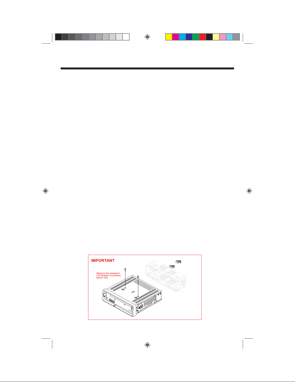
IMPORTANT:
Remove the two transport screws from the top of the unit before installing.
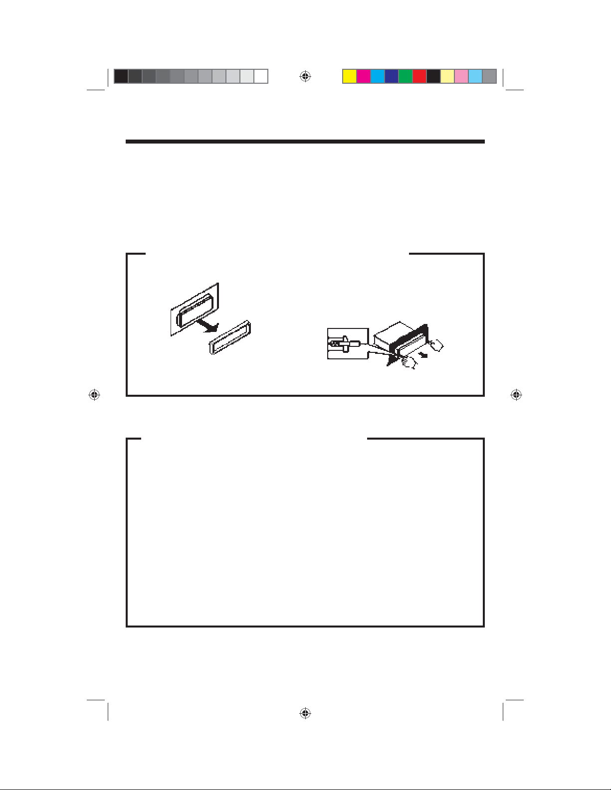
1. Remove the Old Unit from the Dashboard
A. Remove the outer trim frame.
DIN Front Mount
B. Insert the keys supplied with the old unit
into both sides of the unit as shown in
figure below until they click. Pull to remove the old unit from the dashboard.
DO NOT DISCONNECT WIRES AT THIS TIME!
2. Mark Polarity of the Speaker Wires
Marking the polarity of the speaker
wires will make it easier to connect the
existing speakers to the VRCD220S.
Consult wiring diagram of existing head
unit before disconnecting any wires. If a
wiring diagram is not available contact
the manufacturer.
1.
While the old unit is playing, discon-
nect the wires from one speaker.
2. Take a length of masking tape and
fold it around the wire so it forms a
flag.
3. On the masking tape mark the polarity of the speaker wires (+ & - ), as
well as left or right, and front or rear.
4. Double check that you marked the
first speaker correctly by checking
that the speaker wires are the same
at the head unit.
5. Repeat this procedure for all of the
speakers.
6. Mark the power, ground, and any
other wires also
.
4
VRCD220S English PROOF Manual.indd 5VRCD220S English PROOF Manual.indd 5 10/15/08 11:34:13 AM10/15/08 11:34:13 AM
Page 6
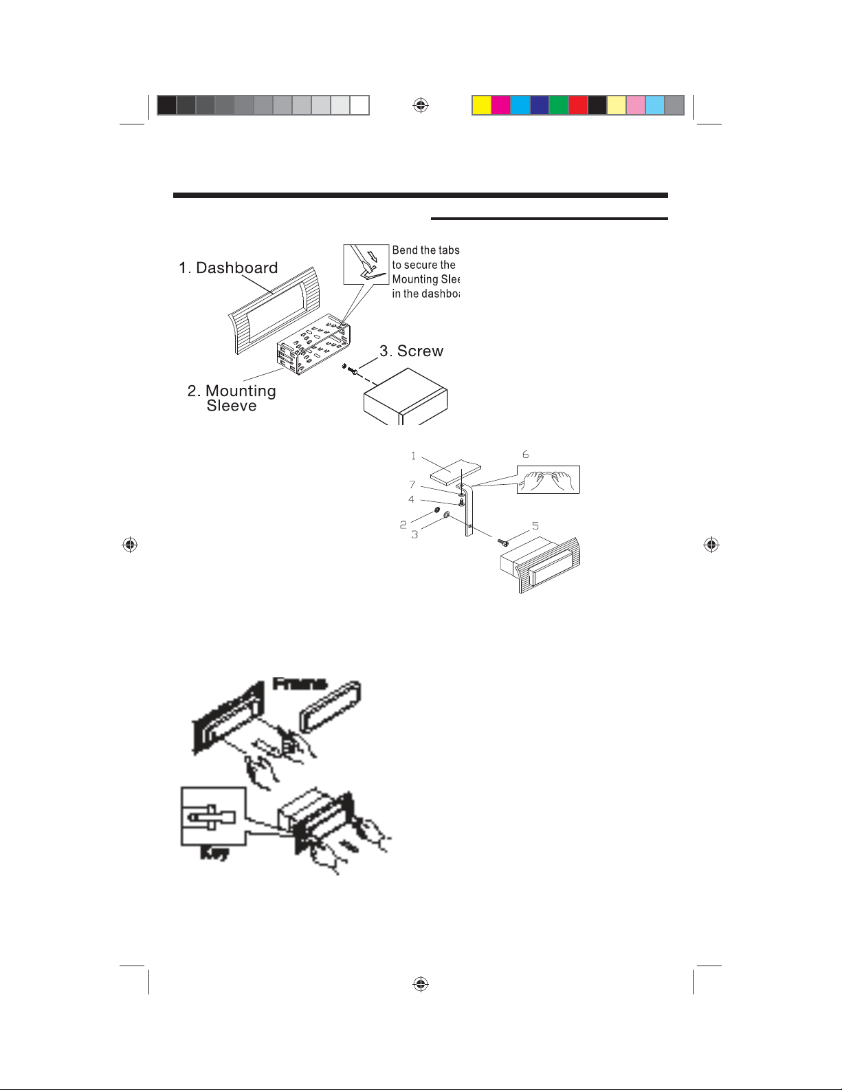
Installation
DIN FRONT-MOUNT (Method A)
Fig. 1
After inserting the Mounting Sleeve
into the dashboard, select tabs on
top, bottom, and sides, then bend
them to secure the mounting sleeve
in the dash board.(Fig. 1)
Follow the diagram in Fig. 2 for installing the rear mounting strap to
the head unit. The rear mounting
strap will help keep the head unit
from moving around inside the dashboard.
Insert fi ngers into the groove in the front of frame to remove it.
Fig. 3
1. Dashboard
2. Nut (5mm)
3. Spring washer
4. Screw (5 x
25mm)
5. Screw
6. Strap
Fig. 2
7. Plain washer
Insert the keys supplied with the unit in the
grooves on both sides. The unit can be installed
or removed from the dashboard using these
keys.(Fig. 3)
5
VRCD220S English PROOF Manual.indd 6VRCD220S English PROOF Manual.indd 6 10/15/08 11:34:14 AM10/15/08 11:34:14 AM
Page 7

Installation
DIN REAR-MOUNT (Method B)
Installation using the screw holes on both sides of the unit.
1. Screw holes on the side of the unit.
2. Screws. Use either truss screws (5 x
8mm) or fl ush surface screws (4 x 8mm),
depending on the shape of the screw
holes in the bracket.
3. Vehicle’s Factory Mounting Bracket
4. Dashboard or Console
5 Hook (Remove this part)
Note: The mounting sleeve, outer trim
ring, and the mounting strap are not used
for this method of installation.
PARTS
2 Keys
1 Hex Nut
2 Lock Washers
1 Sheet Metal Screw
1 Metal Support Strap
2 Flat Washers
1 Mounting Bolt
1 Faceplate Case
1 Faceplate(not shown)
6
VRCD220S English PROOF Manual.indd 7VRCD220S English PROOF Manual.indd 7 10/15/08 11:34:14 AM10/15/08 11:34:14 AM
Page 8

Installation
WIRING CONNECTIONS
GIVE US A CALL, WE'LL HELP YOU INSTALL.
PLEASE DO NOT RETURN PRODUCT TO STORE.
Visit us on the WEB
www.vr-3.com
For Information and Technical Assistance,
Call Toll-Free in U.S.A. and Canada.
1-800-445-1797
7
VRCD220S English PROOF Manual.indd 8VRCD220S English PROOF Manual.indd 8 10/15/08 11:34:15 AM10/15/08 11:34:15 AM
Page 9

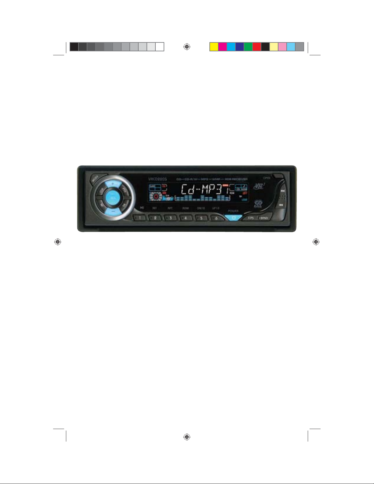
Location of the Controls
12 34 5 7
161920
1. Clock Button
2. Mode Button
3. Volume Up Button
4. SEL Button
5. PTY Button
6. LCD for Track Number, Time, Radio
Frequency, File Type, ID3, RDS, EQ
7. Open Faceplate Button
8.
Next Track/Change Frequency/Fast Forward
9.
Previous Track/Change Frequency/Fast Reverse
10.
Band Button
11. F/PS Button
12. Power Button
13. Pre-set #6/Up 10
14. Pre-set #5/Down 10
15. Pre-set #4/Random
16. Pre-set #3/Repeat
17. Pre-set #2/Intro
18. Pre-set #1/Pause/Play
19. TA Button
20. Volume Down Button
21. AF Button
22. Eject button
23. Reset button
24. Americas/Europe Switch
25. Disc Slot
26. Red LED
101112131415
86
9171821
22
23 24 25 26
To Remove the Faceplate
1. Press the Open Button to open the faceplate.
2. Tilt the faceplate down about half way and push the faceplate to the left, then pull the
it towards you to remove it.
8
VRCD220S English PROOF Manual.indd 9VRCD220S English PROOF Manual.indd 9 10/15/08 11:34:16 AM10/15/08 11:34:16 AM
Page 10

Basic Operation
1. Turning the Unit On / Of f
Press any button to turn the unit on,
WELCOME will be displayed on the LCD to
indicate it is ready for use. Press and hold
the POWER button to turn the unit off.
2. Mode Selection
Press the MODE Button to cycle between
AUX, RADIO and CD modes.
3. Volume
Use the VOL +/- Buttons to adjust the volume level. The higher the VOL number, the
higher the volume level.
4. Bass
Press the “SEL” Button until the display
shows “BAS”. Use the VOL +/- Buttons to
adjust. When DSP is ON, the Bass control
is not available.
5. Treble
Press “SEL” Button until the display shows
“TRE”. Use the VOL +/- Buttons to adjust.
When DSP is ON, the treble control is not
available.
6. Balance
Press “SEL” Button until the display shows
“BAL”, then use the VOL +/- Button to
adjust the balance between the left & right
speakers.
7. F a d e r
Press “SEL” Button five times and the
display shows “FAD”, then use the VOL +/Button to adjust the balance between the
front & rear speakers.
8. Clock
1. While listening to the radio, press the
“CLK” button until the clock is displayed
2. Press and hold the “CLK” button until
the time starts to flash
3. Press the VOL + Button to adjust the
hour
4. Press the VOL – button to adjust the
minutes
5. Press the “CLK” button again or just
leave the the unit idle for a few new settings to take effect.
9. DSP-Preset Equalizer Function
1. Press and hold the “SEL” button until
you hear a beep.
2. Press the “SEL” button to cycle through
the menu choices until you see DSP
OFF. 3. Press the +/- buttons to cycle
through the pre-set EQ settings.
DSP OFF POP M ROCK M
FLAT M CLASS M
4. Leave the unit idle for the new setting to
take effect.
10. Loudness
1. Press and hold the “SEL” Button until
you hear a beep.
2. Press the “SEL” Button until the display
shows “LOUD OFF”.
3. Use the +/- Buttons to select “LOUD
ON” (Loudness effect ON) or “LOUD
OFF” (Loudness effect OFF).
4. Leave the unit idle for the new setting to
take effect
11. Preset Beep Sound Off
1. Press and hold the “SEL” Button until
you hear a beep.
2. Press the “SEL” Button until the display
shows “BEEP ON”.
3. Use the +/- Buttons to select “BEEP
ON” (beep sound on) or “BEEP OFF”
(beep sound off).
4. Leave the unit idle for the new setting to
take effect.
12. Preset Volume Level
You can set the default volume level for the
unit when it is turned ON.
1. Press and hold the “SEL” Button until
you hear a beep.
2. Press the “SEL” Button until the display
shows “VOL LAST”.
Press the +/- Buttons to enter “VOL ADJ “
3.
will be displayed.
4. Press the “SEL” Button and “A- VOL 15”
will be displayed. The number after AVOL indicates the volume level the unit
will default to the next time you turn the
unit ON.
9
VRCD220S English PROOF Manual.indd 10VRCD220S English PROOF Manual.indd 10 10/15/08 11:34:18 AM10/15/08 11:34:18 AM
Page 11

Radio Operation
5. Press the +/- Buttons to adjust the volume level.
6. Leave the unit idle for the new setting to
take effect. The next time you turn the
unit ON, the volume will automatically
be adjusted to the sound level you set
here.
Radio Frequency Selection
The default frequency setting is in your
country mode. However if you want to
change the frequency to Europe or USA,
please follow the step below:
1. Press the Open Button to open the
faceplate.
2. Tilt the faceplate down about half way
and push the faceplate to the left.
3. Pull the faceplate towards you to remove
it.
4. Below the faceplate you will see a switch
with the letter “A” on the right side and
the letter “E” on the left side.
5. For use in the Americas slide the switch
to the left or for use in Europe slide the
switch to the right.
1. Choose a Radio Band
The unit comes with five bands for storing
your favorite radio - three FM Bands (FM1,
FM2, and FM3) and two AM Bands (AM1,
and AM2) selects. Each of the five bands
can store up to six preset stations, for a
total of 30 preset memory stations. 18 FM
Pre-sets and 12 AM Pre-sets.
2. Manual Tune / Seek Function
Manual Tune: Press the “|>>” Button to
adjust the radio to a higher frequency or
press the “<<|” Button to adjust the radio
to a lower frequency.
Seek Function : Press and hold the >>|
Button for about 2 seconds, and the radio
will search forward for the next strongest
frequency, then stop.
3. Press and hold the “|<<” Button for
about 2 seconds, and the radio will search
backward for the next strongest frequency,
then stop.
3. Save Your Preset Stations
There are six numbered preset buttons
which can store and recall stations for each
band. While listening to a radio station you
would like to save as a pre-set, press and
hold one of the buttons numbered 1-6 until
you hear a beep. The button you pressed
is now the pre-set button for that station.
4. Automatic Store/Preset Scan
A
. Automatic Scan & Store
While listening to the Radio, press and
hold the F/PS Button. The receiver will
automatically scan all of the frequencies of
the band you are tuned to.
After scanning the frequencies it will automatically store the strongest signals to the
pre-set buttons.
If there are any stations already saved to
the pre-set buttons, they will be replaced
by the Automatic Scan & Store function.
B.
Scan Saved Stations
Press the F/PS button once to perform the
scanning functions. In FM mode, press
the F/PS button and the stations in all 3
FM bands will be scanned; press this button in AM mode and scan all 2 AM Band
Stations.
RDS Operation
Enhanced Other Networks (EON)
This unit is equipped with the latest technology of EON control. EON control allows
the receiver to monitor other stations for
traffic announcements while you are listening to the Radio or a CD. If there are
any travel announcements on a nearby
local station, then the receiver will tune to
the station, turn up the volume, or interrupt the playback of the CD for the duration of the announcement. At the end of
the announcement the radio will return
to its previous state ready for the next
announcement.
AF - Alternative Frequencies
Press the AF button and the unit will choose
the strongest FM signal for the selected
10
VRCD220S English PROOF Manual.indd 11VRCD220S English PROOF Manual.indd 11 10/15/08 11:34:18 AM10/15/08 11:34:18 AM
Page 12

RDS Operation
station. This means you do not have to
re-tune the radio when driving between
different transmitter coverage areas. When
AF is on, it means RDS information is
received; when AF is flashing, it means
RDS information is not yet received.
TA - Travel Announcements
Press the TA button and the unit will be
activated for reception of traffic announcements from local radio stations.
To choose the TA mode, press the “SEL”
Button for 2 seconds, the display will
show “TA SEEK”. Press the “+/-” Buttons
to choose between “TA SEEK” and “TA
ALARM”, after chooisng, please leave the
unit idle for the new mode setting to take
effect. In “TA SEEK” mode, the unit will
seek for traffic announcement program
when “TA” is pressed; in “TA ALARM”
mode, no “TA/TP” is displayed and the
alarm is turned off.
TP - Traffic Program
The “TP” Function is used to allow the user
to find only those stations that regularly
broadcast traffic bulletins.
sound select button again so that the unit
will show “MASK DPI”.
Press the “+/-” Buttons to toggle between
“MASK DPI” and “MASK ALL” mode. Then
leave the unit idle for the new setting to
take effect.
During “MASK DPI” mode, the unit will
mask only the “AF” which has different “PI”, this is the default mode; during
“MASK ALL” mode, the unit will mask the
AF which has different PI and no RDS signal with high field strength.
RETUNE S/L - SHORT/LONG
This function is to set the initial duration
of automatic TA Search -- Press and
hold the “SEL” button until “TA SEEK” is
shown on the LCD, then Press the “+/-”
Buttons to cycle through the menu selections until “RETUNE_S” is shown, use the
VOL +/- button to choose “RETUNE_S” or
“RETUNE_L”. The default is “RETUNE_S”.
PTY - Program Type
This “PTY” function allow you to select the
type of program you wish to listen to, and
will search for a station broadcasting that
type of program. Press the “PTY” button
once to show the music type. Then press
the 1-6 buttons to choose the different
music types available.
Press the “PTY” button twice to show Talk
Show programing you can search for, then
press a number button 1-6 to choose a
different Talk Show type program. Each
number button can display 3 Talk Show
programs for you to choose.
There are up to 31 pre-defined program
types that allows users to find programing
by genre.
MASK DPI - MASK ALL
Press the “SEL” Button for 2 seconds, the
display will show “TA SEEK”. Press the
11
VRCD220S English PROOF Manual.indd 12VRCD220S English PROOF Manual.indd 12 10/15/08 11:34:18 AM10/15/08 11:34:18 AM
Page 13

CD Operation
Electronic Skip Protection - 12 or 45
seconds
Electronic Skip Protection is ideal for driving on rough roads. Press the “SEL” Button
until the display will show “TA SEEK”. Then
press the “SEL” Button to cycle through
the menu until “ESP12” is displayed indicating that 12 seconds Electronic Skip
Protection will be activated.
With “ESP 12” on the display, use the VOL
“+/-” Buttons to change the setting to “ESP
45”, indicating that 45 seconds Electronic
Skip Protection is activated. Leave the unit
idle for the new setting to take effect.
1. Insert/Eject CD
Insert a disc with MP3 into the CD slot with
label side up. The disc will be automatically
loaded into the unit, even when it is off or
in radio mode. The word “MP3 DISC” will
be displayed
as the CD is loaded. The first file in the root
folder will be played. As the file is playing
“ROOT” will be displayed first, then the if
there is any ID3 information that will be
displayed as the file is playing. Press the
EJECT Button to eject the disc from the
slot. If the disc is not removed from the
slot within 5 seconds, it will automatically
be loaded into the slot again. When the
disc is ejected and removed, the unit will
automatically switch to radio mode.
2. Selecting Tracks
On the Head Unit, press the SEEK >>|
Button to advance CD to the next track.
Track numbers will be shown on the display. Press and hold SEEK >>| to fast
forward. Press the SEEK |<< Button to go
to a previous track. Track numbers will be
shown on the display. Press and hold the
SEEK |<< Button to fast reverse. Disc will
play normally when the SEEK >>| or SEEK
|<< Button is released. On the Remote
Control, use the |<< or >>| Buttons.
3. Play/ Pause CD
Press the No.1 Button to pause the CD.
Press this button again to resume playback.
4. Scanning Tracks
Press the No.2/INT Button to play the first
10 seconds of each track. Press this button again to resume playback.
5. Repeat
Press the No.3/RPT Button to repeat the
same track continuously. “RPT ON” will
appear on the display. Press this button
again to stop repeating.
6. Random
Press the No.4/RDM Button to play all the
tracks in random order. “RDM ON” will
appear on the display. Press this button
again to stop random play.
12
VRCD220S English PROOF Manual.indd 13VRCD220S English PROOF Manual.indd 13 10/15/08 11:34:18 AM10/15/08 11:34:18 AM
Page 14

MP3 & WMA Disc Operation
MP3 & WMA Disc Operation
Electronic Skip Protection-120 Seconds
Electronic Skip Protection is ideal for
driving on rough roads. Electronic Skip
Protection for MP3 & WMA CDs is a default
feature. Please note that this feature supports CDs with Songs encoded by 96Kb/s
and 32000Hz.
For songs encoded in higher quality, the
anti-shock duration will decrease proportionally to the file size.
1. Insert/Eject CD
Insert a disc with MP3 into the CD slot with
label side up. The disc will be automatically
loaded into the unit, even when it is off or
in radio mode. The word “MP3 DISC” will
be displayed
as the CD is loaded. The first file in the root
folder will be played. As the file is playing
“ROOT” will be displayed first, then the if
there is any ID3 information that will be
displayed as the file is playing. Press the
“EJECT” Button to eject the disc from the
slot. If the disc is not removed from the
slot within 5 seconds, it will automatically
be loaded into the slot again. When the
disc is ejected and removed, the unit will
automatically switch to radio mode.
2. Selecting Tracks
On the Head Unit, press the “>>|” Button to
advance CD to the next track. Track numbers will be shown on the display. Press
and hold the “>>|” Button to fast forward.
The disc will play normally when the “>>|”
Button is released. Press the “|<<” Button
to go to a previous track. The track numbers will be shown on the display. Press
and hold the “|<<” Button to fast reverse.
Disc will play normally when the “|<<”
Button is released. On the Remote Control
the “|<<” or “>>|” Buttons operate the
same as on the Head Unit.
4. Play/ Pause CD
On the Head Unit, press the No.1 Button
to pause the CD. Press this button again
to resume playback.
5. Scanning Tracks
On the Head Unit, press the No.2/INT
Button to play the first 10 seconds of each
track. Press this button again to resume
playback.
6. Repeat
On the Head Unit, press the No.3/RPT
Button to repeat the same track continuously. “RPT ON” will appear on the display.
Press this button again to stop repeating.
7. R a ndom
On the Head Unit, press the No.4/RDM
Button to play all the tracks in random
order. “RDM ON” will appear on the display. Press this button again to stop random play.
8. UP 10
Press the No.6/UP10 Button to advance
10 track at a time.
9. DN 10
Press the No.5/DN10 Button to go back 10
track at a time.
Search Modes
There are 4 search modes to help find your
favorite MP3 tracks. The search modes
only works with MP3 CDs, and do not work
with any other type of CDs.
1. Simple Track Search
Press the SEEK |<< or >>| Button to go
to the next track or previous track. Press
the Number 5 button to go back 10 tracks
at once or press the Number 6 button to
advance 10 tracks at once.
2. Track Search
Press the F/PS Button and the display will
show “TRK SCH”. Press the SEL Button so
13
VRCD220S English PROOF Manual.indd 14VRCD220S English PROOF Manual.indd 14 10/15/08 11:34:19 AM10/15/08 11:34:19 AM
Page 15

MP3 & WMA Disc Operation
that “TRK” will blink on the display.
Then use the VOL +/- Button to choose
your desired track and press the SEL
Button again to confirm the selection. The
selected track will be searched for and
then played.
3. File Search
Press the F/PS Button twice and the
display will show “FILE SCH”. Press the
SEL Button to enter the root folder of the
disc. Use the VOL +/- Button to choose a
folder in the root folder, then press the SEL
Button to confirm. The selected folder will
be opened.
4. Character Search
Press the F/PS Button three times and
the display will show “CHAR SCH”. This
is for files by file names. Press the SEL
Button and the first character will blink
on the display. Use the VOL +/- Button to
change the character. Press the SEL button once to confirm the character entered
and advance to the next character. After
you have input the name, press and hold
the SEL Button to confirm. The song nearest alphabetically to the name input will be
found and then begin to play.
AUX IN cable. Use the volume control to
adjust volume.
2. RCA Output
The RCA Output Jack is on the back of the
unit. (Refer to Wiring Diagram) This output
is for connecting amplifier, equalizer, or
other audio component that requires a
pre-amp out connection. (Red = Right,
White = Left)
Follow the manufacturers instructions for
the audio component that you are connecting.
Maintenance
Cleaning the Unit
Do not use any liquids to clean this unit.
Do not use petroleum distillates to clean
this unit. Use a clean, dry cloth to clean
this unit.
Replacing the Fuse
Make sure the amperage matches the
specified value when replacing the fuse(s).
If the fuse is bad, check the power connection and replace the fuse with a new one. If
the same problem occurs, this might indicate a malfunction within the unit.
Warning
AUX IN & RCA Output
1. Auxiliary Input
The Auxiliary Input RCA Jacks are on the
rear of the unit. To use the AUX IN feature
you must use a RCA to 3.5mm cable.
Insert the cable’s RCA plugs into the Red &
White AUX IN jacks on the rear of the unit.
Route the end of the cable with the 3.5mm
jack to an area that is safe and convenient
to the headphone jack of any external
audio device such as walkman and discman. Press the “Mode” button to choose
AUX. Connect any portable audio device
such as a DVD player or VCD player to the
VRCD220S English PROOF Manual.indd 15VRCD220S English PROOF Manual.indd 15 10/15/08 11:34:19 AM10/15/08 11:34:19 AM
When replacing a fuse, do not use a fuse
with a higher amperage rating than the
fuse originally supplied to your unit, otherwise damage will result to your unit.
14
Page 16

Simple Troubleshooting Guide
PROBLEM CAUSE/SOLUTION
No Power Check wiring connections.
Check and make sure the fuse is not blown.
Replace with the proper rating/size fuse.
Some errors occur in the LCD or
nothing functions when buttons
are pressed.
Unable to receive stations Check and make sure the antenna is con-
Poor radio reception Check and make sure the antenna is the
CD’s cannot be loaded
Songs keep skipping The CD is dirty or damaged.
File information shows in LCD but
will not play.
Press the RESET Button.
nected properly.
correct length. Make sure the antenna
is not broken. If the antenna is broken,
replace it. The antenna is poorly grounded. Check and make sure the antenna is
grounded at mounting location.
A CD is already loaded in the player. Eject CD.
Your fi le may be corrupt.
Specifi cations
GENERAL
Operating Power ...................................................... 11 to 16 Volts DC, Negative Ground
Total Maximum Power .......................................................................................140 Watts
RMS Power ................................................................4x7 Watts at 4 Ohms ≤ 1% THD+N
Output Wiring ....................................................... Designed for using four speakers only
RCA line out .......................................................................... low-level outputs - 1000MV
Output Impedance ...................................................... Compatible 4 to 8 Ohm Speakers
Fuses ................................................................................................... 1 amp and 10 amp
Dimensions ...............................................................178mm(W) x 178mm(D) x 51mm (H)
Weight ..................................................................................................................... 2.3 Kg
CD PLAYER
Signal / Noise Ratio ................................................................................................>60dB
Frequency Response ................................................................................... 20 Hz~20KHz
Channel Separation ................................................................................................>50dB
D / A Converter .......................................................................................................... 1 Bit
FM TUNER
Tuning Range ................................... (USA) - 87.5 - 107.9MHz, (Europe) - 87.5 - 108 MHz
FM Sensitivity .......................................................................................................... 12dBu
Stereo Separation @ 1 Khz ....................................................................................... 35dB
AM TUNER
Tuning Range......................(USA) -- 530-1710 KHz, (Europe) -- 522-1620 KHz
Am Sensitivity ......................................................................................................... 30dBu
15
VRCD220S English PROOF Manual.indd 16VRCD220S English PROOF Manual.indd 16 10/15/08 11:34:19 AM10/15/08 11:34:19 AM
Page 17

Limited Warranty
VIRTUAL REALITY SOUND LABS® products are designed and manufactured to provide a high level of troublefree performance. VIRTUAL REALITY SOUND LABS warrants, to the original purchaser, that its products are
free from defects in material and workmanship for 30 days from the date of original purchase, as part of our
commitment to product excellence. VIRTUAL REALIT Y SOUND LABS and/or it’s affi liates routinely improves
the designs, materials or production methods of its existing products. Because it is impractical to publicize all
changes in ever y product, we reserve the right to make such changes without notice.
CONDITIONS OF WARRANTY:
If during the 30 day warrant y period your new product is found to be defective, VIRTUAL RE ALIT Y SOUND LABS
will repair such defect, or replace the product, without charge for parts or labor subject to the following conditions:
All repairs must be performed by VIRTUAL REALIT Y SOUND LABS and/or its affi liates in Eatontown, New Jersey.
1.
2.
The equipment must not have been altered or been damaged through negligence, accident, or improper opera-
tion.
3.
The replacement of par ts are exempted from this warranty when replacement is necessary due to normal wear and
tear.
4. All warranty claims must be accompanied by a copy of the sales receipt or bill of sale.
5. Repair or replacement parts supplied by VIRTUAL RE ALIT Y SOUND LABS under this warranty are protected
only for the unexpired por tion of the original warranty.
6. In the case of car stereos, this warranty does not extend to the elimination of car static or motor noise; correction of antenna problems; costs incurred for the removal or reinstallation of the product; damage to tapes,
speakers, accessories or car electrical systems.
7. VIRTUAL REALITY SOUND LABS will not be responsible for any charge incurred for installation.
OWNER’S RESPONSIBILITIES:
VIRTUAL REALITY SOUND LABS will make every effor t to provide warranty service within a reasonable period of time.
SHOULD YOU HAVE ANY QUESTIONS ABOUT SERVICE RECEIVED, OR IF YOU WOULD LIKE ASSISTANCE IN
OBTAINING SERVICE, PLE ASE CALL TOLL FREE 1-800-445-1797, 8:30am - 4:30pm EST.
In order to provide you with the proper warranty service, we request that you adhere to the following procedure:
1. Include a copy of your sales receipt or bill of sale with your unit when it is returned for warranty service.
2. If it is necessary to return your product for service, please return it securely packed, preferably in the original
shipping carton, and freight and insurance prepaid to the following address: VIRTUAL REALITY SOUND LABS,
Service Department, 41 James Way, Eatontown, New Jersey 07724.
3. Please include a detailed explanation of the problem you are having.
4. If your p rod uct is fou nd b y V IRT UAL RE ALIT Y SO UND LABS to have a de fec t in ma ter ial or wor kma nsh ip, w ith in
the warrant y peri od, it will be re pa ired or replaced at no c ha rge and returned to you p re paid. Wh er e permit ted by
Iaw VIRTUAL REALITY SOUND LABS liability shall be limited to that set forth in this warranty. This warranty shall
be the exclusive remedy of the purchaser.
VIRTUAL REALITY SOUND LABS® makes no other warranty of any kind, expressed or implied; and all implied
warranties, are hereby disclaimed by VIRTUAL REALITY SOUND LABS and excluded from this warranty, VIRTUAL REALITY SOUND L ABS and/or its affi liates, the manufacturer, distributor and seller shall not be liable for
any injury, loss or damage, incidental or consequential, arising out of the use or intended use of the product.
VRCD220S English PROOF Manual.indd 17VRCD220S English PROOF Manual.indd 17 10/15/08 11:34:19 AM10/15/08 11:34:19 AM
Page 18

©2008 Intellectual Solutions Inc., All rights reser ved. All designs, logos and images are the exclusive property of
Intellectual Solutions Inc. and/or its af fi liates. US and Foreign patents pending. 072208 Printed in China 00000
VRCD220S English PROOF Manual.indd 18VRCD220S English PROOF Manual.indd 18 10/15/08 11:34:19 AM10/15/08 11:34:19 AM
 Loading...