


User's Guide
Hammerfall® DSP System
Multiface II
The most compact professional multitrack recording system ever!
TotalMix™
24 Bit / 96 kHz 9
SyncAlign® |
ZLM® |
SyncCheck® |
PCI Busmaster Digital I/O System
PCI and CardBus Interface
8 + 8 + 2 Channels Analog / ADAT / Stereo Interface
Hi-Power Hi-End Headphone Output
24 Bit / 96 kHz

General
1 |
Introduction ............................................................... |
6 |
2 |
Package Contents ..................................................... |
6 |
3 |
System Requirements .............................................. |
6 |
4 |
Brief Description and Characteristics..................... |
7 |
5 |
Hardware Installation |
|
5.1 |
PCI Interface ........................................................... |
7 |
5.2 |
CardBus Card ......................................................... |
7 |
5.3 |
Notes on Power Supply .......................................... |
8 |
6 |
First Usage – Quick Start |
|
6.1 |
Connectors and Front Panel.................................. |
8 |
6.2 |
Quick Start ............................................................. |
9 |
6.3 |
Notes on Laptops and CardBus........................... |
10 |
7 |
Accessories ............................................................. |
11 |
8 |
Warranty................................................................... |
12 |
9 |
Appendix .................................................................. |
12 |
Driver Installation and Operation - Windows
10 |
Driver and Firmware |
|
|
|
10.1 |
Driver Installation ................................................. |
16 |
|
10.2 |
Driver Update ....................................................... |
16 |
|
10.3 |
Deinstalling the Drivers ........................................ |
16 |
|
10.4 |
Firmware Update.................................................. |
17 |
11 |
Configuring the Multiface II |
|
|
|
11.1 |
Settings Dialog ..................................................... |
18 |
|
11.2 |
Clock Modes – Synchronization........................... |
20 |
12 |
Operation and Usage |
|
|
|
12.1 |
Playback............................................................... |
22 |
|
12.2 |
DVD Playback (AC-3 / DTS) ................................ |
23 |
|
12.3 |
Notes on WDM ..................................................... |
24 |
|
12.4 |
Multi-client Operation ........................................... |
25 |
|
12.5 |
Digital Recording .................................................. |
26 |
|
12.6 |
Analog Recording................................................. |
27 |
13 |
Operation under ASIO 2.0 |
|
|
|
13.1 |
General ................................................................ |
27 |
|
13.2 |
Known Problems .................................................. |
27 |
14 |
Operation under GSIF............................................. |
28 |
|
15 |
Using more than one Hammerfall DSP ................. |
29 |
|
16 |
DIGICheck ................................................................ |
29 |
|
17 |
Hotline – Troubleshooting |
|
|
|
17.1 |
General ................................................................ |
30 |
|
17.2 |
Installation ............................................................ |
31 |
18 |
Diagrams |
|
|
|
18.1 Channel Routing ASIO 96 kHz ............................ |
32 |
|
|
18.2 Channel Routing WDM 96 kHz............................ |
33 |
|
2 |
User's Guide HDSP System Multiface II © RME |

Driver Installation and Operation - Mac OS X
19 |
Driver and Flash Update |
|
|
|
19.1 |
Driver Installation ................................................. |
36 |
|
19.2 |
Driver Update....................................................... |
36 |
|
19.3 |
Flash Update........................................................ |
36 |
20 |
Configuring the Multiface II |
|
|
|
20.1 |
Settings Dialog..................................................... |
37 |
|
20.2 Clock Modes – Synchronization .......................... |
39 |
|
21 |
Mac OS X FAQ |
|
|
|
21.1 Round about Driver Installation ........................... |
41 |
|
|
21.2 |
MIDI doesn't work ................................................ |
41 |
|
21.3 |
Supported Sample Rates..................................... |
42 |
|
21.4 |
Repairing Disk Permissions................................. |
42 |
|
21.5 |
PCI Compatibility ................................................. |
42 |
|
21.6 |
Various Information.............................................. |
42 |
22 |
Hotline – Troubleshooting ..................................... |
43 |
|
23 |
Diagram: Channel Routing at 96 kHz ...................... |
44 |
|
Disconnect Mode, Connections and TotalMix
24 |
Disconnect Mode .................................................... |
46 |
|
25 |
Analog Connections |
|
|
|
25.1 |
Line Inputs ........................................................... |
46 |
|
25.2 |
Line Outputs......................................................... |
47 |
|
25.3 |
Phones................................................................. |
47 |
26 |
Digital Connections |
|
|
|
26.1 |
ADAT ................................................................... |
48 |
|
26.2 |
SPDIF................................................................... |
48 |
|
26.3 |
Word Clock........................................................... |
49 |
|
26.4 |
MIDI...................................................................... |
49 |
27 |
Word Clock |
|
|
|
27.1 Technical Description and Background............... |
50 |
|
|
27.2 |
Cables and Termination....................................... |
50 |
|
27.3 |
General Operation................................................ |
51 |
28 |
TotalMix: Routing and Monitoring |
|
|
|
28.1 |
Overview .............................................................. |
52 |
|
28.2 |
The User Interface ............................................... |
54 |
|
28.3 |
Elements of a Channel ........................................ |
55 |
|
28.4 |
Tour de TotalMix .................................................. |
55 |
|
28.5 |
Submix View ........................................................ |
57 |
|
28.6 |
Mute and Solo ...................................................... |
57 |
|
28.7 |
Quick Access Panel ............................................. |
58 |
|
28.8 |
Presets ................................................................. |
58 |
|
28.9 |
Monitor Panel ....................................................... |
60 |
|
28.10 |
Preferences........................................................ |
60 |
|
28.11 |
Editing the Names.............................................. |
61 |
|
28.12 |
Hotkeys .............................................................. |
62 |
|
28.13 |
Menu Options..................................................... |
63 |
|
28.14 |
Level Meter ........................................................ |
64 |
User's Guide HDSP System Multiface II © RME |
3 |

29 |
TotalMix: The Matrix |
|
|
|
29.1 |
Overview .............................................................. |
65 |
|
29.2 |
Elements of the Matrix View ................................ |
65 |
|
29.3 |
Usage................................................................... |
65 |
|
29.4 |
Advantages of the Matrix ..................................... |
66 |
30 |
TotalMix Super-Features |
|
|
|
30.1 |
ASIO Direct Monitoring (Windows only) .............. |
66 |
|
30.2 |
Selection and Group based Operation ................ |
67 |
|
30.3 |
Copy Routings to other Channels........................ |
67 |
|
30.4 |
Delete Routings.................................................... |
67 |
|
30.5 |
Recording a Subgroup (Loopback)...................... |
68 |
|
30.6 |
Using external Effects Devices ............................ |
68 |
31 |
TotalMix MIDI Remote Control |
|
|
|
31.1 |
Overview .............................................................. |
70 |
|
31.2 |
Mapping ............................................................... |
70 |
|
31.3 |
Setup.................................................................... |
71 |
|
31.4 |
Operation ............................................................. |
71 |
|
31.5 |
Simple MIDI Control............................................. |
72 |
|
31.6 |
Loopback Detection ............................................. |
73 |
Technical Reference
32 |
Tech Info .................................................................. |
76 |
|
33 |
Technical Specifications |
|
|
|
33.1 |
Analog .................................................................. |
77 |
|
33.2 |
Digital ................................................................... |
77 |
|
33.3 |
Digital Inputs ........................................................ |
78 |
|
33.4 |
Digital Outputs...................................................... |
78 |
|
33.5 |
MIDI...................................................................... |
78 |
|
33.6 |
General ................................................................ |
79 |
34 Technical Background |
|
|
34.1 |
Lock and SyncCheck ........................................... |
79 |
34.2 |
Latency and Monitoring........................................ |
80 |
34.3 |
DS – Double Speed ............................................. |
81 |
34.4 |
AES/EBU – SPDIF ............................................... |
82 |
35 |
Diagrams |
|
|
|
35.1 |
Block Diagram Multiface II ................................... |
83 |
|
35.2 |
Connector Pinouts ............................................... |
84 |
4 |
User's Guide HDSP System Multiface II © RME |

User's Guide
Multiface II
General
User's Guide HDSP System Multiface II © RME |
5 |

1. Introduction
Thank you for choosing the RME Hammerfall DSP system. This unique audio system is capable of transferring analog and digital audio data directly to a computer from practically any device. The latest Plug and Play technology guarantees a simple installation, even for the inexperienced user. The numerous unique features and well thought-out configuration dialog puts the Hammerfall DSP at the very top of the range of computer-based audio interfaces.
The package contains drivers for Windows 2000 SP4, Windows XP/Vista/64, and Mac OS X PPC and Intel.
Our high-performance philosophy guarantees maximum system performance by executing as many functions as possible not in the driver (i.e. the CPU), but directly within the audio hardware.
2. Package Contents
Please check your Hammerfall DSP component's package to include each of the following:
PCI / PCIe Interface
•PCI card HDSP Rev 1.9
•Quick Info guide
•RME Driver CD
•Cable IEEE1394, 4.5 m (15 ft)
CardBus / ExpressCard Interface
•CardBus or ExpressCard card
•Quick Info guide
•RME Driver CD
•Cable IEEE1394, 4 m (13 ft)
•12 V car cable
•Battery cable
•Power supply 12 V / 1.25 A and power cord
Multiface II
•I/O-box Multiface II
•Quick Info guide
•RME Driver CD
•1 optical cable (TOSLINK), 2 m (6.6 ft)
3. System Requirements
•Windows 2000 SP4, Windows XP, Mac OS X (10.28 or higher)
•PCI Interface: a free PCI rev. 2.1 Busmaster slot
•PCI Express Interface: a free PCI Express slot, 1 Lane, version 1.1
•CardBus Interface: a free PCMCIA slot type II, CardBus-compatible
•Express Card interface: a free ExpressCard/34 slot
6 |
User's Guide HDSP System Multiface II © RME |

4. Brief Description and Characteristics
•Hammerfall design: 0% (zero!) CPU load, even using all 36 ASIO channels
•All settings can be changed in real-time
•Analog, ADAT and SPDIF I/Os can be used simultaneously
•8 buffer sizes/latencies available: 1.5 / 3 / 6 / 12 / 23 / 46 / 93 / 186 ms
•4 channels 96 kHz/24 bit record/playback via ADAT optical (S/MUX)
•Clock modes slave and master
•Automatic and intelligent master/slave clock control
•Unsurpassed Bitclock PLL (audio synchronization) in ADAT mode
•Word clock input and output
•Zero Latency Monitoring for latency-free submixes and perfect ASIO Direct Monitoring
•SyncAlign guarantees sample aligned and never swapping channels
•SyncCheck tests and reports the synchronization status of input signals
•1 x MIDI I/O, 16 channels high-speed MIDI
•Separate analog Line/hi-power headphone output for independent submix
•DIGICheck DSP: Level meter in hardware, peakand RMS calculation
•TotalMix: 720 channel mixer with 40 bit internal resolution
5. Hardware Installation
5.1PCI Interface
Before installing the PCI card, please make sure the computer is switched off and the power cable is disconnected from the mains supply. Inserting or removing a PCI card while the computer is in operation can cause irreparable damage to both motherboard and card!
1.Disconnect the power cord and all other cables from the computer.
2.Remove the computer's housing. Further information on how to do this can be obtained from your computer´s instruction manual.
3.Important: Before removing the card from its protective bag, discharge any static in your body by touching the metal chassis of the PC.
4.Insert the PCI card firmly into a free PCI slot, press and fasten the screw.
5.Replace the computer's housing.
6.Reconnect all cables including the power cord.
7.Connect PCI interface and Multiface using the supplied cable (IEEE1394). This is a standard FireWire cable (6-pin).
5.2 CardBus Card
Before inserting the CardBus card make sure the complete HDSP system is ready for operation!
1.Connect the CardBus card with the RPM using the supplied cable.
2.Insert the CardBus card with the Hammer logo up into a PCMCIA slot.
3.Plug the power jack of the supplied switching power supply into the connector labeled AUX, on the rear of the RPM.
4.Connect power cord to power supply, plug into AC outlet. The green LED of the power supply and the red LED of the Multiface will light up.
5.Switch on the notebook and boot the operating system.
User's Guide HDSP System Multiface II © RME |
7 |

5.3 Notes on Power Supply
•The CardBus card delivers no power to the Multiface. Therefore a hi-tech switching power supply is included.
•The PCI card operates as power supply for the attached Multiface via the FireWire cable. An external power supply is not required.
The Multiface II draws a high startup current of more than 2 A during initialisation. Current at 12 Volt operating voltage: unloaded 720 mA (8.6 Watts), loaded 1 A (12 Watts). Supply voltage range DC 8 V – 28 V, AC 8 V – 20 V.
The Multiface II has a higher power consumption as the original Multiface. Therefore the Multiface II will only work with a HDSP PCI card revision 1.9 or higher!
While the Multiface causes a load of about 9 Watts to the PCI card, the Multiface II will cause a load of about 12 Watts. The HDSP PCI cards built until recently are not designed for such a load. The voltage regulator found on the PCI card will switch off after a short time due to overheating. The HDSP PCI revision 1.9 uses a more powerful regulator.
Still the Multiface II can also be used with an older HDSP PCI card, in case the Multiface II is powered by an external power supply. With a voltage higher than 10 Volts, the power supply of the PCI card is automatically switched off. We recommend the RME switching power supply 12 V / 1.25 A, included with the CardBus card, but also available separately.
6. First Usage – Quick Start
6.1 Connectors and Front Panel
The front of the Multiface II features a MIDI input and output, a stereo headphone output with volume control, two switches to select the analog reference level, and several status LEDs.
MIDI IN and OUT represent the MIDI input and output, realized as 5-pin DIN jacks.
The LEDs MIDI IN and OUT indicate sent or received data for the MIDI ports.
The Digital State LEDs (WC, SPDIF, ADAT) indicate a valid input signal separately for each digital input. Additionally, RME's exclusive SyncCheck indicates if one of these inputs is locked, but not synchronous to the others, in which case the LED will flash. See also chapter 11.2 / 20.2, Clock Modes - Synchronization.
The red HOST LED lights up when the power supply or the computer is switched on, thus signalling the presence of operating voltage. At the same time it operates as Error LED, in case the I/O-box wasn’t initialised, or the connection to the interface has been interrupted (Error, cable not connected etc.). It flashes then. After the firmware had been loaded the LED turns off, thus signalling a proper operation.
ANALOG LEVEL has two switches with three positions each, to select the reference level of the eight analog inputs and outputs on the rear.
Phones is a low impedance line output of highest quality, which can produce a sufficient volume undistorted even when used with headphones.
The volume of the phones output is adjusted with the pot VOL.
8 |
User's Guide HDSP System Multiface II © RME |

The rear panel of the Multiface II has eight analog inputs and outputs, the Power socket (only necessary with CardBus operation), Word Clock input and output, and both digital inputs and outputs ADAT and SPDIF.
ADAT I/O (TOSLINK): Can also be used as optical SPDIF input and output, if set up accordingly in the Settings dialog. The Settings dialog is started by clicking on the hammer symbol in the Task Bar's system tray.
SPDIF I/O coaxial (RCA): Fully AES/EBU compatible by transformer-coupling and level adjustment. The Multiface accepts the commonly used digital audio formats, SPDIF as well as AES/EBU.
Word Clock I/O (BNC). The word clock input is not terminated.
The hook serves as strain relief. Originally only thought of as power cable retention (feed cable through, or knot it around the hook), it's big enough to also handle some other cables of the Multiface. The hook is mounted using a thread, therefore can be turned and even completely removed.
6.2 Quick Start
After the driver installation (see chapter 10 / 19) connect the TRS-jacks with the analog signal source. The input sensitivity can be changed with the switch ANALOG LEVEL INPUTS, assuring the highest signal to noise ratio will be achieved. Try to achieve an optimum input level by adjusting the source itself. Raise the source’s output level until the peak level meters in TotalMix reach about –3 dB.
The analog line inputs of the Multiface can be used with +4 dBu and -10 dBV signals. The electronic input stage can handle balanced (TRS jacks) and unbalanced (TS jacks) input signals correctly.
The Multiface's digital outputs provide SPDIF (AES/EBU compatible) and ADAT optical signals at the corresponding ports.
On the analog playback side (the DA side), the switch ANALOG LEVEL OUTPUTS performs a coarse adjustment of the analog output level of all rear analog outputs.
An additional stereo output is available on the front. The output level can be set using the VOL pot. This output is a very low impedance type, which can also be used to connect headphones.
User's Guide HDSP System Multiface II © RME |
9 |
6.3 Notes on Laptops and CardBus
The HDSP system uses the notebook’s PCMCIA type II port as CardBus interface. Compared to a PC-Card, which only has access to the outdated ISA-bus, CardBus is a 32 bit PCI interface. Like with a desktop system it’s not possible to remove a PCI device while in operation. First the operating system has to receive a ‚removal request’, then the device has to be stopped. Finally the card can be pulled out of the PCMCIA slot.
Windows
When inserting the CardBus card it usually will be detected automatically by the notebook hardware and then the operating system. A beep signals the detection. In rare cases detection will fail. If so, simply remove the card and insert it again.
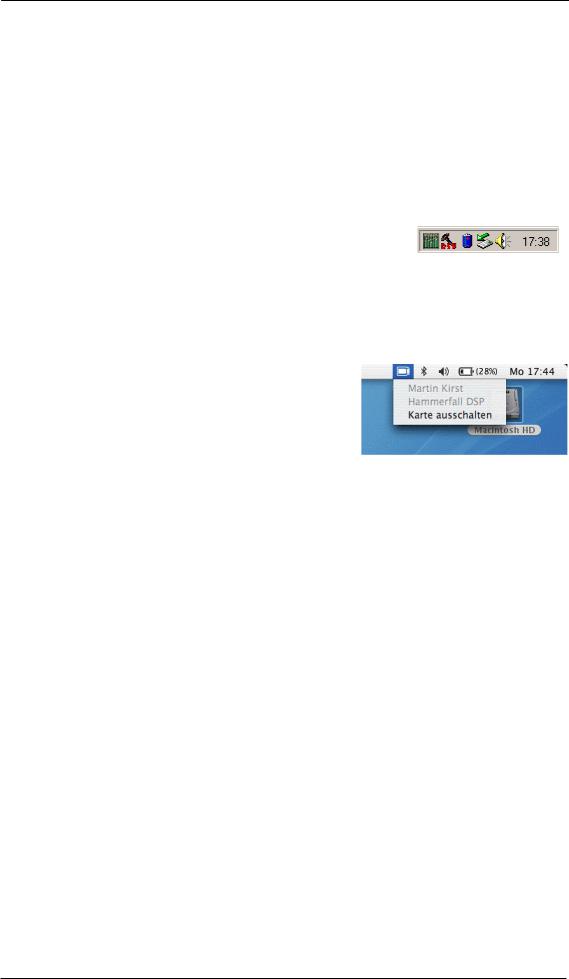
To remove the hardware click on the green arrow symbol in the systray. It is possible to stop the HDSP directly, or to first call up the info dialog by double clicking the symbol, and then stopping it.
Mac OS X
When inserting the CardBus card it usually is detected automatically by the notebook hardware and then by the Mac OS. A CardBus icon will appear on the top menu. A mouse click on the icon opens a drop-down menu, showing the card's name (Hammerfall DSP) and an option to switch it off.
To remove the CardBus card click on the menu entry 'Power off card'. The Mac OS internally de-installs the CardBus card and switches off power (the red Host LED begins to blink). The card can now be pulled out of the PCMCIA slot.
Tech Infos
The Hammerfall DSP System was tested thoroughly on several notebooks by RME. Basically the CardBus card operates with any tested device. Our website hosts several interesting Tech Infos with background information:
HDSP-System: Notebook Tests – Compatibility and Performance
HDSP System: Notebook Basics - Notebook Hardware
HDSP System: Notebook Basics - Background Knowledge and Tuning
The mobile operation of the HDSP system can cause problems. Explanations and solutions on digital noise, ground loops, headphone operation and Line Out wiring, power supplies and the mobile operation with battery can be found in the Tech Info:
HDSP System: Notebook Basics - The Audio Notebook in Practise.
10 |
User's Guide HDSP System Multiface II © RME |
7. Accessories
RME offers several optional accessories. Additionally parts of the HDSP system are available separately.
Part Number |
Description |
36000 |
19“, 1UH Universal rack holder |
This 19" rack holder has holes for Digiface and Multiface. Two units can be installed side by side in any combination. The rack holder also includes holes for nearly all 19" half-rack units from other manufacturers.
36001 |
Firewire cable IEEE1394 6M/6M, 1 m (3.3 ft) |
|
36002 |
Firewire cable IEEE1394 6M/6M, 3 m (9.9 ft) |
|
36005 |
Firewire cable IEEE1394 6M/6M, |
5 m (16.4 ft) |
36010 |
Firewire cable IEEE1394 6M/6M, |
10 m (32.8 ft) |
Firewire cable for the HDSP system, both sides 6-pin male. Cable longer than 16 ft is not allowed for FireWire, therefore hard to get in computer shops. However the HDSP system does not use FireWire protocol, therefore can operate flawlessly even with a cable length of up to 50ft (15 m).
36003 |
Optical cable, TOSLINK, 0.5 m (1.6 ft) |
36004 |
Optical cable, TOSLINK, 1 m (3.3 ft) |
36006 |
Optical cable, TOSLINK, 2 m (6.6 ft) |
36007 |
Optical cable, TOSLINK, 3 m (9.9 ft) |
36008 |
Optical cable, TOSLINK, 5 m (16.4 ft) |
36009 |
Optical cable, TOSLINK, 10 m (33 ft) |
Standard lightpipe with TOSLINK connectors, RME approved quality.
37011 |
Power supply for HDSP CardBus card |
Robust and light weigth switching power supply, 100V-240V AC, 12V 1.25 A DC.
User's Guide HDSP System Multiface II © RME |
11 |

8. Warranty
Each individual Hammerfall DSP undergoes comprehensive quality control and a complete test at IMM before shipping. The usage of high grade components allow us to offer a full two year warranty. We accept a copy of the sales receipt as valid warranty legitimation.
If you suspect that your product is faulty, please contact your local retailer. The warranty does not cover damage caused by improper installation or maltreatment - replacement or repair in such cases can only be carried out at the owner’s expense.
Audio AG does not accept claims for damages of any kind, especially consequential damage. Liability is limited to the value of the Hammerfall DSP. The general terms of business drawn up by Audio AG apply at all times.
9. Appendix
RME news, driver updates and further product information are available on our website:
http://www.rme-audio.com
Manufacturer:
IMM Elektronik GmbH, Leipziger Strasse 32, D-09648 Mittweida
Trademarks
All trademarks, registered or otherwise, are the property of their respective owners. RME, DIGI96, SyncAlign, ZLM, SyncCheck, DIGICheck and Hammerfall are registered trademarks of RME Intelligent Audio Solutions. Multiface, TMS and TotalMix are trademarks of RME Intelligent Audio Solutions. Alesis and ADAT are registered trademarks of Alesis Corp. ADAT optical is a trademark of Alesis Corp. Microsoft, Windows 2000 and Windows XP are registered trademarks or trademarks of Microsoft Corp. Steinberg, Cubase and VST are registered trademarks of Steinberg Media Technologies GmbH. ASIO is a trademark of Steinberg Media Technologies GmbH.
Copyright © Matthias Carstens, 12/2007. Version 3.0
Current driver version: W2k/XP: 3.056, Mac OS X Intel: 1.71
Although the contents of this User’s Guide have been thoroughly checked for errors, RME can not guarantee that it is correct throughout. RME does not accept responsibility for any misleading or incorrect information within this guide. Lending or copying any part of the guide or the RME Driver CD, or any commercial exploitation of these media without express written permission from RME Intelligent Audio Solutions is prohibited. RME reserves the right to change specifications at any time without notice.
12 |
User's Guide HDSP System Multiface II © RME |

CE / FCC Compliance
CE
This device has been tested and found to comply with the limits of the European Council Directive on the approximation of the laws of the member states relating to electromagnetic compatibility according to RL89/336/EWG and RL73/23/EWG.
FCC
This equipment has been tested and found to comply with the limits for a Class B digital device, pursuant to Part 15 of the FCC Rules. These limits are designed to provide reasonable protection against harmful interference in a residential installation. This equipment generates, uses, and can radiate radio frequency energy and, if not installed and used in accordance with the instructions, may cause harmful interference to radio communications. However, there is no guarantee that interference will not occur in a particular installation. If this equipment does cause harmful interference to radio or television reception, which can be determined by turning the equipment off and on, the user is encouraged to try to correct the interference by one or more of the following measures:
-Reorient or relocate the receiving antenna.
-Increase the separation between the equipment and receiver.
-Connect the equipment into an outlet on a circuit different from that to which the receiver is connected.
-Consult the dealer or an experienced radio/TV technician for help.
RoHS
This product has been soldered lead-free and fulfils the requirements of the RoHS directive.
ISO 9001
This product has been manufactured under ISO 9001 quality management. The manufacturer, IMM Elektronik GmbH, is also certified for ISO 14001 (Environment) and ISO 13485 (medical devices).
Note on Disposal
According to the guide line RL2002/96/EG (WEEE – Directive on Waste Electrical and Electronic Equipment), valid for all european countries, this product has to be recycled at the end of its lifetime.
In case a disposal of electronic waste is not possible, the recycling can also be done by IMM Elektronik GmbH, the manufacturer of the Multiface.
For this the device has to be sent free to the door to:
IMM Elektronik GmbH
Leipziger Straße 32
D-09648 Mittweida
Germany
Shipments not prepaid will be rejected and returned on the original sender's costs.
User's Guide HDSP System Multiface II © RME |
13 |

14 |
User's Guide HDSP System Multiface II © RME |
User's Guide
Multiface II
Driver Installation and Operation - Windows
User's Guide HDSP System Multiface II © RME |
15 |

10. Driver and Firmware
10.1 Driver Installation
After the interface has been installed correctly, connected to the Multiface (see 5. Hardware Installation), and the computer has been switched on, Windows will recognize the new hardware component and start its ‘Hardware Wizard’. Insert the RME Driver CD into your CD-ROM drive, and follow further instructions which appear on your computer screen. The driver files are located in the directory \WDM on the RME Driver CD.
Windows will install the Hammerfall DSP System driver, and will register the card in the system as a new audio device. After a reboot the Multiface is ready for use.
In case the warning messages 'Digital signature not found', 'Do not install driver', 'not certified driver' or similar come up: Don't listen to Microsoft, listen to us and continue with the installation.
In case the Hardware Wizard does not show up automatically after installation of the card, do not attempt to install the drivers manually! An installation of drivers for non-recognized hardware will cause a blue screen when booting Windows!
10.2 Driver Update
RME's driver updates often include a new hdsp.inf file. Also the revision number of the hardware might change (after a flash update). To prevent Windows 2000/XP from using an old hdsp32.inf, or to copy some of the old driver files, be sure NOT to let Windows search for the driver! Instead tell Windows what to do.
Under >Control Panel /System /Device Manager /Sound, Video and Game Controllers /RME Hammerfall DSP /Properties /Driver< you'll find the 'Update Driver' button. Select 'Install from a list or specific location (advanced)', click 'Next', select 'Don't search I will choose the driver to install', click 'Next', then 'Have Disk'. Now point to the driver update's directory.
This method also allows to install older drivers than the currently installed ones.
10.3 Deinstalling the Drivers
A deinstallation of the HDSP's driver files is not necessary – and not supported by Windows anyway. Thanks to full Plug & Play support, the driver files will not be loaded after the hardware has been removed. If desired these files can then be deleted manually.
Unfortunately Windows Plug & Play methods do not cover the additional autorun entries of TotalMix, the Settings dialog, and the registration of the ASIO driver. Those entries can be removed from the registry through a software deinstallation request. This request can be found (like all deinstallation entries) in Control Panel, Software. Click on the entry 'RME Hammerfall DSP (WDM)'.
16 |
User's Guide HDSP System Multiface II © RME |

10.4 Firmware Update
The Flash Update Tool updates HDSP PCI cards or CardBus cards to the latest version. It requires an already installed driver.
Start the program hdsp_fut.exe or hdsp_pcie_fut.exe. The Flash Update Tool displays the current revision of the HDSP interface, and whether it needs an update or not. If so, then please manually select if a PCI card (desktop computer) or a CardBus card (laptop) shall be flashed. Next simply press the 'Update' button. A progress bar will indicate when the flash process is finished. The bar moves slowly first (program), then faster (verify).
If more than one interface card is installed, all cards can be flashed by changing to the next tab and repeating the process.
After the update the PCI/CardBus cards need to be reset. This is done by powering down and shutting off the PC. A warm boot is not enough!
PCI card revision 1.8 or up (black PCB), CardBus with 6-pin FireWire connector
When the update fails (status: failure), the card's second BIOS will be used from the next cold boot on (Secure BIOS Technology). Therefore the card stays fully functional. The flash process should then be tried again on a different computer.
All other PCI cards, and CardBus with 15-pin flat connector
When the update fails (status: failure) the flash process should be repeated several times, until no error message occurs anymore. If the failure message is displayed nonetheless, the interface will most propably no longer work when the computer is switched off and on again. The interface then has to be re-programmed at the factory. We have invested a lot of work to prevent the system from getting in this state. If it happens despite our efforts, the best advice we can give is to not switch off the computer! As long as it is not switched off the old programming of the PCI/CardBus interface will stay active, and you can continue to work with the system using the old drivers
Note: In case the hardware revision changes, Windows 2000/XP will start the hardware assistant and wants to install new drivers. Do NOT let Windows search for new drivers, but follow the instructions given in chapter 10.2.
User's Guide HDSP System Multiface II © RME |
17 |

11. Configuring the Multiface II
11.1 Settings Dialog
Configuration of the HDSP system Multiface is done via its own settings dialog. The panel 'Settings' can be opened:
• by clicking on the hammer symbol in the Task Bar's system tray
The mixer of the Hammerfall DSP Systems (TotalMix) can be opened:
• by clicking on the mixer icon in the Task Bar's system tray
The hardware of the HDSP system offers a number of helpful, well thought-of practical functions and options which affect how the card operates - it can be configured to suit many different requirements. The following is available in the 'Settings' dialog:
•Input selection
•Level of analog I/Os
•Configuration of digital I/Os
•Synchronization behaviour
•State of input and output
Any changes made in the Settings dialog are applied immediately - confirmation (e.g. by clicking on OK or exiting the dialog) is not required. However, settings should not be changed during playback or record if it can be avoided, as this can cause unwanted noises. Also, please note that even in 'Stop' mode, several programs keep the recording and playback devices open, which means that any new settings might not be applied immediately.
The status displays at the bottom of the dialog box give the user precise information about the current status of the system, and the status of all digital signals.
SyncCheck indicates whether there is a valid signal (Lock, No Lock) for each input (Word Clock, ADAT, SPDIF), or if there is a valid and synchronous signal (Sync). The AutoSync Ref(erence) display shows the input and frequency of the current sync source.
18 |
User's Guide HDSP System Multiface II © RME |

WDM
SyncAlign guarantees synchronous channels when using MME multitrack software. This option should only be switched off in case the used software does not work correctly with SyncAlign activated.
With Interleaved activated, WDM devices can be used as 8-channel devices (see chapter 12.4).
Buffer Size
The setting Buffer Size determines the latency between incoming and outgoing ASIO and GSIF data, as well as affecting system stability (see chapter 13/14).
SyncCheck
SyncCheck indicates whether there is a valid signal (Lock, No Lock) for each input (Word Clock, ADAT, SPDIF), or if there is a valid and synchronous signal (Sync). The AutoSync Reference display shows the input and frequency of the current sync source.
Options
TMS activates the transmission of Channel Status data and Track Marker information of the SPDIF input.
Disconnect interrupts the communication between I/O-box and PCI or CardBus card. In case the Multiface has been configured using the Settings dialog and TotalMix, Disconnect allows to use it Stand-Alone (without a connected computer), after a power supply has been attached.
SPDIF In
Defines the input for the SPDIF signal. 'Coaxial' relates to the RCA
socket, 'Optical' to the optical TOSLINK input.
SPDIF Out
The SPDIF output signal is constantly available at the phono plug. After selecting 'Optical' it is also routed to the optical TOSLINK output. For further details about the settings ‘Professional’, ‘Emphasis’ and ‘Non-Audio’, please refer to chapter 26.2.
SPDIF Freq.
Displays the sample rate of the signal at the SPDIF input.
Time Code
Time Code from the input ADAT Sync. Not available for the Multiface II.
User's Guide HDSP System Multiface II © RME |
19 |

I/O Box State
This field displays the current state of the I/O-box.
Error: I/O-box not connected or missing power
Detected: The interface has found an I/O-box and tries to load the firmware
Connected: Communication between interface and I/O-box operates correctly
Disconnected: Communication between interface and I/O-box has been interrupted, I/O-box continues operation
Word Clock Out
The word clock output signal usually equals the current sample rate. Selecting Single Speed causes the output signal to always stay within the range of 32 kHz to 48 kHz. So at 96 kHz sample rate, the output word clock is 48 kHz.
Clock Mode
The unit can be configured to use its internal clock source (Master), or the clock source predefined via Pref. Sync Ref (AutoSync).
Pref. Sync Ref.
Used to pre-select the desired clock source. If the selected source isn't available, the unit will change to the next available one. The current clock source and sample rate is displayed in the
AutoSync Ref display.
The automatic clock selection checks and changes between the clock sources Word Clock, ADAT and SPDIF.
System Clock
Shows the current clock state of the HDSP system. The system is either Master (using its own clock) or Slave (see AutoSync Ref).
11.2 Clock Modes - Synchronisation
In the digital world, all devices are either the ‘Master’ (clock source) or a ‘Slave’ synchronized to the master. Whenever several devices are linked within a system, there must always be a single master clock. The Hammerfall DSP’s intelligent clock control is very user-friendly, being able to switch between clock modes automatically. Selecting AutoSync will activate this mode.
In AutoSync mode, the system constantly scans all digital inputs for a valid signal. If this signal corresponds with the current playback sample rate, the card switches from the internal quartz (AutoSync Ref displays 'Master') to a clock generated from the input signal (AutoSync Ref displays 'Slave'). This allows on-the-fly recording, even during playback, without having to synchronize the card to the input signal first. It also allows immediate playback at any sample rate without having to reconfigure the card.
AutoSync guarantees that normal record and record-while-play will always work correctly. In certain cases however, e.g. when the inputs and outputs of a DAT machine are connected directly to the Hammerfall DSP, AutoSync may cause feedback in the digital carrier, so synchronization breaks down. To remedy this, switch the HDSP’s clock mode over to 'Master'.
Remember that a digital system can only have one master! If the HDSP’s clock mode is set to 'Master', all other devices must be set to ‘Slave’.
20 |
User's Guide HDSP System Multiface II © RME |
The Hammerfall DSP's ADAT optical input and the SPDIF input operate simultaneously. Because there is no input selector however, the HDSP has to be told which of the signals is the sync reference (a digital device can only be clocked from a single source). This is why the system has been equipped with automatic clock source selection, which adopts the first available input with a valid digital signal as the clock reference input. The input currently used as sync reference is shown in the AutoSync Ref status field, together with its sample frequency.
Via Pref. Sync Ref (preferred synchronization reference) a preferred input can be defined. As long as the card sees a valid signal there, this input will be designated as the sync source, otherwise the other inputs will be scanned in turn. If none of the inputs are receiving a valid signal, the card automatically switches clock mode to ‘Master’.
To cope with some situations which may arise in studio practice, setting ‘Pref Sync Ref’ is essential. One example: An ADAT recorder is connected to the ADAT1 input (ADAT1 immediately becomes the sync source) and a CD player is connected to the SPDIF input. Try recording a few samples from the CD and you will be disappointed. Few CD players can be synchronized. The samples will inevitably be corrupted, because the signal from the CD player is read with the (wrong) clock from the ADAT i.e. out of sync. In this case, 'Pref Sync Ref' should be temporarily set to SPDIF.
If several digital devices are to be used simultaneously in a system, they not only have to operate with the same sample frequency but also be synchronous with each other. This is why digital systems always need a single device defined as ‘master’, which sends the same clock signal to all the other (‘slave’) devices. RME’s exclusive SyncCheck technology (first implemented in the Hammerfall) enables an easy to use check and display of the current clock status. The ‘SyncCheck’ field indicates whether no signal (‘No Lock’), a valid signal (‘Lock’) or a valid and synchronous signal (‘Sync’) is present at each of the digital clock source inputs. The ‘AutoSync Ref’ display shows the current sync source and the measured frequency.
In practice, SyncCheck provides the user with an easy way of checking whether all digital devices connected to the system are properly configured. With SyncCheck, finally anyone can
master this common source of error, previously one of the most complex issues in the digital studio world.
Thanks to its AutoSync technique and lightning fast PLLs, the HDSP is not only capable of handling standard frequencies, but also any sample rate between 28 and 103 kHz. Even the word clock input, which most users will use in varispeed operation, allows any frequency between 28 kHz and 105 kHz.
At 88.2 or 96 kHz: If one of the ADAT inputs has been selected in ‘Pref Sync Ref’, the sample frequency shown in the ‘SPDIF In’ field differs from the one shown in ‘AutoSync Ref’. The card automatically switches to its Sample Split mode here, because ADAT optical inputs and outputs are only specified up to 48 kHz. Data from/to a single input/output is spread over two channels, the internal frequency stays at 44.1 or 48 kHz. In such cases, the ADAT sample frequency is only half the SPDIF frequency.
User's Guide HDSP System Multiface II © RME |
21 |

12. Operation and Usage
12.1 Playback
The HDSP system can play back audio data only in supported modes (channels, PCM) and formats (sample rate, bit resolution). Otherwise an error message appears (for example at 22 kHz and 8 bit).
In the audio application being used, HDSP must be selected as output device. This can often be found in the Options, Preferences or Settings menus under Playback Device, Audio Devices, Audio etc.
We strongly recommend switching off all system sounds (via >Control Panel /Sounds<). Also HDSP should not be the Preferred Device for playback, as this could cause loss of synchronization and unwanted noises. If you feel you cannot do without system sounds, you should consider buying a cheap Blaster clone and select this as Preferred Device in >Control Panel /Multimedia /Audio<.
The screenshot shows a typical configuration dialog of a (stereo) wave editor. After selecting a device, audio data is sent to an analog or digital (ADAT / SPDIF) port, depending on which has been selected as playback device.
Increasing the number and/or size of audio buffers may prevent the audio signal from breaking up, but also increases latency i.e. output is delayed. For synchronized playback of audio and MIDI (or similar), be sure to activate the checkbox ‘Get position from audio driver’.
The HDSP system’s ADAT optical interface allows sample rates of up to 96 kHz using a standard ADAT recorder. Single-channel data at this frequency requires two ADAT channels, achieved using the Sample Multiplexing technique. This reduces the number of available ADAT channels from 8 to 4. Under Windows MME, channels are routed to ADAT devices in doublespeed mode as follows:
• Only stereo pairs (1+2) and (3+4) of the ADAT port are available
This kind of implementation allows a problem-free usage of the ADAT port in both Single and Double Speed, as the routing doesn't change. However, the hardware spreads the data differently: Channel 1 is transmitted via channels 1 and 2, channel 2 via 3 and 4 etc.
Please refer to the diagram in chapter 18.2. Routing for record and playback is identical.
22 |
User's Guide HDSP System Multiface II © RME |

12.2 DVD-Playback (AC-3/DTS) under MME
AC-3 / DTS
When using popular DVD software player like WinDVD and PowerDVD, their audio data stream can be sent to any AC-3/DTS capable receiver, using the Hammerfall DSP's SPDIF output. For this to work the SPDIF output wave device has to be selected in >Control Panel/ Sounds and Multimedia/ Audio<. Also check 'use preferred device only'.
You will notice that the DVD software's audio properties now allow to use 'SPDIF Out', 'Use SPDIF' or to 'activate SPDIF output'. When selecting these, the software will transfer the nondecoded digital multichannel data stream to the Hammerfall DSP.
This 'SPDIF' signal sounds like chopped noise at highest level. Therefore the Multiface automatically activates the non-audio bit within the digital data stream, to prevent most SPDIF receivers from accepting the signal, and to prevent any attached equipment from being damaged.
Multichannel
PowerDVD can also operate as software decoder, sending a DVD's multichannel data stream directly to the analog outputs of the Multiface. Supported are all modes, from 2 to 8 channels, at 16 bit resolution and 48 kHz sample rate. Playback via the ADAT output of the Multiface is also supported.
For this to work the option Interleaved has to be activated in the Settings dialog, an output wave device of the HDSP has to be selected in >Control Panel/ Sounds and Audio Devices/ Audio<, and 'Use only default devices' has to be checked. Additionally the loudspeaker setup, found under >Volume/ Speaker Settings/ Advanced< has to be changed from Stereo to 5.1 Surround.
PowerDVD's and WinDVD's audio properties now list several multichannel modes. If one of these is selected, the software sends the decoded analog multichannel data to the HDSP.
The device selected as Default Sound playback device defines the first playback channel. Note that this device can not be chosen freely. An interleaved playback with more than 2 channels can only be done in blocks of eight channels. Therefore the starting device has to be channel 1/2 or 9/10.
The typical channel assignment for surround playback is:
1 (first chosen playback channel) - Left
2 - Right
3 - Center
4 - LFE (Low Frequency Effects)
5 - SR (Surround Right)
6 - SL (Surround Left)
Note 1: Setting the card to be used as system playback device is against common sense, as professional cards are not specialized to play back system sounds, and shouldn't be disturbed by system events. To prevent this, be sure to re-assign this setting after usage, or to disable any system sounds (tab Sounds, scheme 'No audio').
Note 2: The DVD player will be synced backwards from the HDSP card. This means when using AutoSync and/or word clock, the playback speed and pitch follows the incoming clock signal.
User's Guide HDSP System Multiface II © RME |
23 |

12.3 Notes on WDM
The driver offers a WDM streaming device per stereo pair, like HDSP Multiface (1+2). WDM streaming is Microsoft's current driver and audio system, directly embedded into the operating system. WDM streaming is nearly unusable for professional music purposes, as all data is processed by the so called Kernel Mixer, causing a latency of at least 30 ms. Additionally, WDM can perform sample rate conversions unnoticed, cause offsets between record and playback data, block channels unintentionally and much more. Therefore, for general operation, RME recommend not to use WDM devices.
WDM streaming also replaces the former DirectSound. Synthesizers and Samplers, which achieved latencies below 10 ms using DirectSound, are forced to use WDM in Windows XP, now operating at high latency. Meanwhile most of these programs support ASIO as low latency driver interface.
Several programs do not offer any direct device selection. Instead they use the playback device selected in Windows under <Control Panel/ Sounds and Multimedia/ Audio>. Such software often requires the special functions provided by WDM, and therefore will operate better when using a WDM device. Please note that selecting the HDSP to be used as system playback device is against our recommendations, as professional interfaces should not be disturbed by system events.
The program Sonar from Cakewalk is unique in many ways. Sonar uses the so called WDM Kernel Streaming, bypassing the WDM mixer, thus achieves a similar performance to ASIO.
Because of the driver's multichannel streaming ability (option Interleaved, see chapter 12.4), Sonar not only finds the stereo device mentioned above, but also the 8-channel interleaved devices, and adds the channel number at the end:
HDSP Multiface (1+2) is the first stereo device HDSP Multiface (3+4) is the next stereo device
HDSP Multiface (1+2) 3/4 are the channels 3/4 of the first 8-channel interleaved device.
We recommend to not use these special interleaved devices. Also note that it is not possible to use one stereo channel twice (the basic and the interleaved device), even with different applications.
24 |
User's Guide HDSP System Multiface II © RME |

12.4 Multi-client Operation
RME audio interfaces support multi-client operation. This means several programs can be used at the same time. Also all formats, like ASIO, WDM and GSIF can be used simultaneously. The use of multi-client operation requires to follow two simple rules:
•Multi-client operation requires identical sample rates!
I.e. it is not possible to use one software with 44.1 kHz and the other with 48 kHz.
•Different software can not use the same channels at the same time.
If for example Cubase uses channels 1/2, this playback pair can't be used in Gigasampler/Studio (GSIF) nor under WDM (WaveLab etc.) anymore. This is no limitation at all, because TotalMix allows any output routing, and with this a playback of multiple software on the same hardware outputs. Note that the inputs can be used at the same time, as the driver sends the data to all applications simultaneously.
ASIO Multi-client
RME audio interfaces support ASIO multi-client operation. It is possible to use more than one ASIO software at the same time. Again the sample rate has to be identical, and each software has to use its own playback channels. Once again the same inputs can be used simultaneously.
RME's sophisticated tool DIGICheck is an exception to this rule. It operates like an ASIO host, using a special technique to access playback channels already occupied. Therefore DIGICheck is able to analyse and display playback data from any software, no matter which format the software uses.
Multi-Client and Multi-Channel using WDM
The WDM streaming devices of our driver can operate as usual stereo devices, or as 8-channel devices. The option Interleaved in the Settings dialog determines the current mode.
Interleaved not active: The WDM devices operate as usual stereo devices. The multi-client operation works as described above with WDM, ASIO and GSIF.
Interleaved active: The WDM devices can also be used as 8-channel devices. Unfortunately the Kernel Mixer, active with any WDM playback, then always occupies and blocks 8 channels at once, even when WaveLab or the Media Player perform just a stereo playback (2 channels). So:
If any stereo pair within an 8-channel group is used, the whole 8-channel group is blocked. As a result, no second stereo pair of this group can be used, neither with ASIO nor GSIF.
The eight 8-channel groups are: channels 1 to 8 and 9 to 16.
Starting ASIO or GSIF playback on any of the stereo pairs of an 8-channel group prior to starting a WDM playback will prevent the Kernel Mixer from opening the 8-channel device, as two of its channels are already in use. The Kernel Mixer then automatically reverts to open a stereo device for a stereo playback.
User's Guide HDSP System Multiface II © RME |
25 |
12.5 Digital Recording
Unlike analog soundcards which produce empty wave files (or noise) when no input signal is present, digital I/O cards always need a valid input signal to start recording.
To take this into account, RME included a comprehensive I/O signal status display (showing sample frequency, lock and sync status) in the Settings dialog, and status LEDs for each input.
If a 48 kHz signal is fed to the input and the application is set to 44.1 kHz, Check Input stops the system from recording. This prevents faulty takes, which often go unnoticed until later on in the production. Such tracks appear to have the wrong playback rate - the audio quality as such is not affected.
The sample frequency shown in the Settings dialog (see chapter 11, screenshot Settings) is useful as a quick display of the current configuration (the box itself and all connected external equipment). If no sample frequency is recognized, it will read ‘No Lock’.
This way, configuring any suitable audio application for digital recording is simple. After selecting the required input, Hammerfall DSP displays the current sample frequency. This parameter can then be changed in the application’s audio attributes (or similar) dialog.
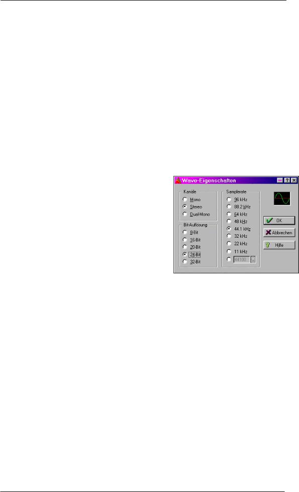
The screenshot to the right shows a typical dialog used for changing basic parameters such as sample frequency and resolution in an audio application.
Any bit resolution can be selected, providing it is supported by both the audio hardware and the software. Even if the input signal is 24 bit, the application can still be set to record at 16-bit resolution. The lower 8 bits (and therefore any signals about 96dB below maximum level) are lost entirely. On the other hand, there is nothing to gain from recording a 16-bit signal at 24-bit resolution - this would only waste precious space on the hard disk.
It often makes sense to monitor the input signal or send it directly to the output. This can be done at zero latency using TotalMix (see chapter 28).
An automated control of real-time monitoring can be achieved by Steinberg’s ASIO protocol with our ASIO 2.0 drivers and all ASIO 2.0 compatible programs. When 'ASIO Direct Monitoring' has been switched on, the input signal is routed in real-time to the output whenever a recording is started (punch-in).
Note: Under MME the feature 'Check Input' prevented recordings done at wrong sample rates. Under WDM this functionality is limited. With Check Input activated Windows will automatically (and without notice) perform a sample rate conversion. With Check Input deactivated the recording will simply be performed with the wrong sample rate, with a detuned playback later on. Therefore Check Input has been removed from the Settings dialog of the WDM driver.
26 |
User's Guide HDSP System Multiface II © RME |
 Loading...