


User's Guide
Digiface AES
USB 2.0 Digital I/O System
USB Bus Powered
6 Channel AES / SPDIF Interface
8 Channel ADAT Interface
2 + 4 Channel Analog Interface
24 Bit / 192 kHz Digital Audio
High Quality SRC
30 x 16 Matrix Router
MIDI Input / Output
Full Stand-Alone Operation
Class Compliant Operation
TotalMix FX
™
24 Bit / 192 kHz
SteadyClock
FS ™
SyncCheck
™
2
User's Guide Digiface AES © RME
Safety Instructions and Proper use
Read the manual carefully and completely before using the device. Pay attention to the
following information on how to use and operate the Digiface AES safely. Improper use
can lead to loss of warranty claims (see warranty statement on page 102).
Proper Use
The Digiface AES is a digital interface for professional audio applications for use with CE approved class B computers.
To comply with the European CE standard, the Digiface AES must be used with
CE approved Class B computers. All connecting cables must be shielded. The
computer and all cables connected to the Digiface AES must be properly
grounded. Operation with non-certified computers and cables may cause interference to other devices as well as the Digiface AES.
Do not open chassis
No user serviceable parts inside. Refer service to qualified service personnel.
To reduce the risk of fire or electric shock do not expose this device to rain or
moisture. Prevent moisture and water from entering the device. Never leave a
pot with liquid on top of the device. Do not use this product near water, i. e.
swimming pool, bathtub or wet basement. Danger of condensation inside –
don't turn on before the device has reached room temperature.
Installation
Surface may become hot during operation – ensure sufficient ventilation.
Avoid direct sun light and do not place it near other sources of heat, like radiators or stoves. When mounting in a rack, leave some space between this
device and others for ventilation.
Unauthorized servicing/repair voids warranty. Only use accessories specified by the
manufacturer.

User's Guide Digiface AES © RME
3
Safety Instructions and Proper Use ....................... 2
General
1 Introduction ............................................................... 8
2 Package Contents ..................................................... 8
3 System Requirements .............................................. 8
4 Brief Description and Characteristics .................... 8
5 First Usage - Quick Start
5.1 Connectors – Controls - Display ............................. 9
5.2 Quick Start ............................................................ 11
5.3 Menu and Navigation ............................................ 11
5.4 Overview Menu Structure ..................................... 13
5.5 Special Options ..................................................... 14
Installation and Operation - Windows
6 Hardware, Driver and Firmware Installation
6.1 Hardware and Driver Installation ............................. 16
6.2 De-installing the Drivers ....................................... 16
6.3 Firmware Update ................................................. 16
7 Configuring the Digiface – Settings Dialog
7.1 General ................................................................ 17
7.2 Option WDM Devices .......................................... 19
8 Operation and Usage
8.1 Playback .............................................................. 21
8.2 DVD Playback (AC-3 / DTS) ................................ 21
8.3 Channel Count under WDM ................................. 22
8.4 Multi-client Operation ........................................... 22
8.5 Analog Recording ................................................ 23
8.6 Digital Recording.................................................. 23
8.7 Clock Modes - Synchronization ........................... 24
9 Operation under ASIO
9.1 General ................................................................ 25
9.2 Channel Count under ASIO ................................. 25
9.3 Known Problems .................................................. 26
10 Using more than one Digiface AES ....................... 26
11 DIGICheck Windows ............................................... 27
12 Hotline – Troubleshooting ..................................... 28

4
User's Guide Digiface AES © RME
Installation and Operation - Mac OS X
13 Hardware, Driver and Firmware Installation
13.1 Hardware and Driver Installation .......................... 30
13.2 De-installing the Drivers ....................................... 30
13.3 Firmware Update .................................................. 30
14 Configuring the Digiface
14.1 Settings Dialog ..................................................... 31
14.2 Clock Modes - Synchronization ........................... 32
15 Mac OS X FAQ
15.1 MIDI doesn't work................................................. 33
15.2 Repairing Disk Permissions ................................. 33
15.3 Supported Sample Rates ..................................... 33
15.4 Channel Count under Core Audio ........................ 33
15.5 Various Information .............................................. 34
16 Using more than one Digiface ............................... 34
17 DIGICheck Mac ........................................................ 35
18 Hotline – Troubleshooting ...................................... 36
Inputs and Outputs
19 Analog Inputs .......................................................... 38
20 Analog Outputs
20.1 Line, XLR ............................................................. 38
20.2 Headphones / Line Out ........................................ 38
20.3 DC-coupled Outputs (CV/Gate) ........................... 39
21 Digital Connections
21.1 AES/EBU .............................................................. 40
21.2 SPDIF (Coaxial, Optical) ...................................... 40
21.3 ADAT .................................................................... 41
21.4 MIDI ...................................................................... 41
21.5 Sample rate Converter (SRC) .............................. 42
Stand-Alone Operation
22 Operation and Usage
22.1 General................................................................. 44
22.2 Settings at the Unit ............................................... 44
22.3 Store / Load Setups at the Unit ............................ 44
22.4 Storing Setups from the Computer ...................... 44
23 Examples
23.1 8-Channel AD/DA-Converter ............................... 45
23.2 2-Channel Mic Preamp ........................................ 45
23.3 Monitor Mixer ....................................................... 45
23.4 Digital Format Converter ...................................... 45
23.5 Analog/Digital Routing Matrix ............................... 45
23.6 Jitter Remover ...................................................... 45

User's Guide Digiface AES © RME
5
TotalMix FX
24 Routing and Monitoring
24.1 Overview .............................................................. 48
24.2 The User Interface ............................................... 50
24.3 The Channels ....................................................... 51
24.3.1 Settings ........................................................ 53
24.3.2 Equalizer ...................................................... 54
24.4 Section Control Room .......................................... 56
24.5 The Control Strip .................................................. 57
24.5.1 View Options ................................................ 58
24.5.2 Snapshots - Groups ..................................... 59
24.5.3 Channel Layout – Layout Presets ................ 60
24.5.4 Scroll Location Markers ............................... 61
24.6 Preferences .......................................................... 62
24.6.1 Store for Current or All Users ...................... 63
24.7 Settings ................................................................ 64
24.7.1 Mixer Page ................................................... 64
24.7.2 MIDI Page .................................................... 65
24.7.3 OSC Page .................................................... 66
24.7.4 Aux Devices ................................................. 67
24.8 Hotkeys and Usage.............................................. 68
24.9 Menu Options ....................................................... 69
24.10 Menu Window ...................................................... 70
25 The Matrix
25.1 Overview .............................................................. 71
25.2 Elements of the Matrix View ................................ 71
25.3 Operation ............................................................. 71
26 Tips and Tricks
26.1 ASIO Direct Monitoring (Windows) ...................... 72
26.2 Copy a Submix ..................................................... 72
26.3 Doubling the Output Signal (Mirror) ..................... 72
26.4 Delete a Submix ................................................... 72
26.5 Copy and Paste everywhere ................................ 72
26.6 Recording a Submix - Loopback .......................... 73
26.7 MS Processing ..................................................... 74
27 MIDI Remote Control
27.1 Overview .............................................................. 75
27.2 Mapping ............................................................... 75
27.3 Setup .................................................................... 76
27.4 Operation ............................................................. 76
27.5 MIDI Control ......................................................... 77
27.6 Stand-Alone MIDI Control .................................... 78
27.7 Loopback Detection ............................................. 80
27.8 OSC (Open Sound Control) ................................. 80
28 DAW Mode ............................................................... 80
29 TotalMix Remote ..................................................... 81

6
User's Guide Digiface AES © RME
Class Compliant Mode
30 General ..................................................................... 84
31 System Requirements............................................. 84
32 Operation ................................................................. 85
32.1 Useful Hints .......................................................... 85
32.2 Class Compliant under Windows/Mac OS X........ 86
33 Supported Inputs and Outputs .............................. 86
34 Front panel Operation ............................................. 87
35 Audio Routing and Processing .............................. 87
36 Setups ...................................................................... 88
Technical Reference
37 Technical Specifications
37.1 Analog .................................................................. 90
37.2 MIDI ...................................................................... 91
37.3 Digital ................................................................... 91
37.4 Digital Inputs ........................................................ 91
37.5 Digital Outputs ...................................................... 92
37.6 General................................................................. 92
38 Technical Background
38.1 Lock and SyncCheck ........................................... 93
38.2 Latency and Monitoring ........................................ 94
38.3 USB Audio ............................................................ 95
38.4 DS – Double Speed ............................................. 96
38.5 QS – Quad Speed ................................................ 96
38.6 SteadyClock FS ................................................... 97
39 Diagrams
39.1 Block Diagram Digiface AES ............................... 98
39.2 Connector Pinouts ................................................ 99
Miscellaneous
40 Accessories ........................................................... 102
41 Warranty ................................................................. 102
42 Appendix ................................................................ 102
43 Declaration of Conformity .................................... 104

User's Guide Digiface AES © RME
7
User's Guide
Digiface AES
General

8
User's Guide Digiface AES © RME
1. Introduction
Thank you for choosing the Digiface AES. This compact audio interface is capable of transferring
analog and digital audio data from any source directly to Windows and Mac computers. Numerous
unique features include flexible clocking, well thought-out Settings dialogs, Sample Rate Conversion and supreme analog circuitry. All this realizes a quick, comfortable and efficient operation of
the Digiface AES.
The package contains drivers for Windows 7 / 8 / 10 / 11 and macOS (11 or higher, Intel / M1 /
M2).
2. Package Contents
Please check your Digiface AES package contains each of the following:
Digiface AES
Cable USB 2.0, 1.8 m (6 ft)
MIDI breakout cable
External switched power supply, lockable connector, DC 12 V 24 W
Power cord
3. System Requirements
Windows 7 or up, Intel macOS (11 or up)
1 x USB 2.0 or USB 3.0 port
Computer with at least Intel Core i5 CPU
4. Brief Description and Characteristics
All settings can be changed in real-time
Buffer sizes/latencies from 48 up to 8192 samples selectable
Intuitive and efficient operation via LC-display
2 digitally controlled microphone/Line inputs in studio quality
2 balanced Line outputs, level switchable +19 dBu / +13 dBu / +4 dBu
2 channels 192 kHz Record/Playback via AES (XLR)
2 channels 192 kHz Record/Playback via SPDIF coaxial (RCA)
2 channels 192 kHz Record/Playback via SPDIF optical
SRC einem dieser Eingänge frei zuweisbar
8 channels 48 kHz Record/Playback via ADAT optical
Clock modes slave and master
Automatic and intelligent master/slave clock control
Unsurpassed Bitclock PLL (audio synchronization) in ADAT mode
SteadyClock FS: Jitter-immune, super-stable digital clock
SyncAlign guarantees sample aligned and never swapping channels
SyncCheck tests and reports the synchronization status of input signals
TotalMix for latency-free submixes and perfect ASIO Direct Monitoring
TotalMix: 480 channel mixer with 46 bit internal resolution
TotalMix FX: 3-band EQ and Low Cut
1 x MIDI I/O, 16 channels high-speed Low-Jitter MIDI
1 x low impedance headphone output
DIGICheck DSP: Level meter in hardware, peak- and RMS calculation

User's Guide Digiface AES © RME
9
5. First Usage – Quick Start
5.1 Connectors – Controls – Display
The front of the Digiface AES features two line and microphone inputs, a stereo headphone output, a rotary encoder with push functionality, four buttons, a graphical colour display and two
status LEDs.
The Neutrik combo sockets of the two Mic/Line inputs
provide XLR and 6.3 mm / 1/4" TRS connection. They
have LEDs for phantom power (48V) indication.
The analog outputs 7 and 8 feed the headphones output Phones. This low impedance output of highest
quality is able to drive headphones at higher levels undistorted, no matter if low or high impedance headphones are used.
The four keys and the encoder,
the high-resolution and clear col-
our display, and a well thoughtout menu structure enable the
user to quickly change and config-
ure the device’s settings com-
pletely without a computer. Help
notes and clear markers in the
display guide the user through all
functions.
When the Global Level Meter screen is shown, the rotary encoder sets the monitoring volume of
Main Out directly at the device. Pushing the button will change to Phones volume control, as
indicated in the right lower corner of the screen.
Digital State. On the right side the main screen shows the current sample rate and the state of
all digital input signals. AES, SPDIF and ADAT indicate a valid input signal separately for each
digital input. Additionally, RME's exclusive SyncCheck indicates if one of these inputs is locked,
but not synchronous to the others, in which case the corresponding field will flash. See also chapter 8.7 / 14.2, Clock Modes - Synchronization. The field USB will change to CC when in Class
Compliant mode.
State MIDI. Between the fields ADAT and USB two yellow lines indicate incoming and outgoing
MIDI data.
10
User's Guide Digiface AES © RME
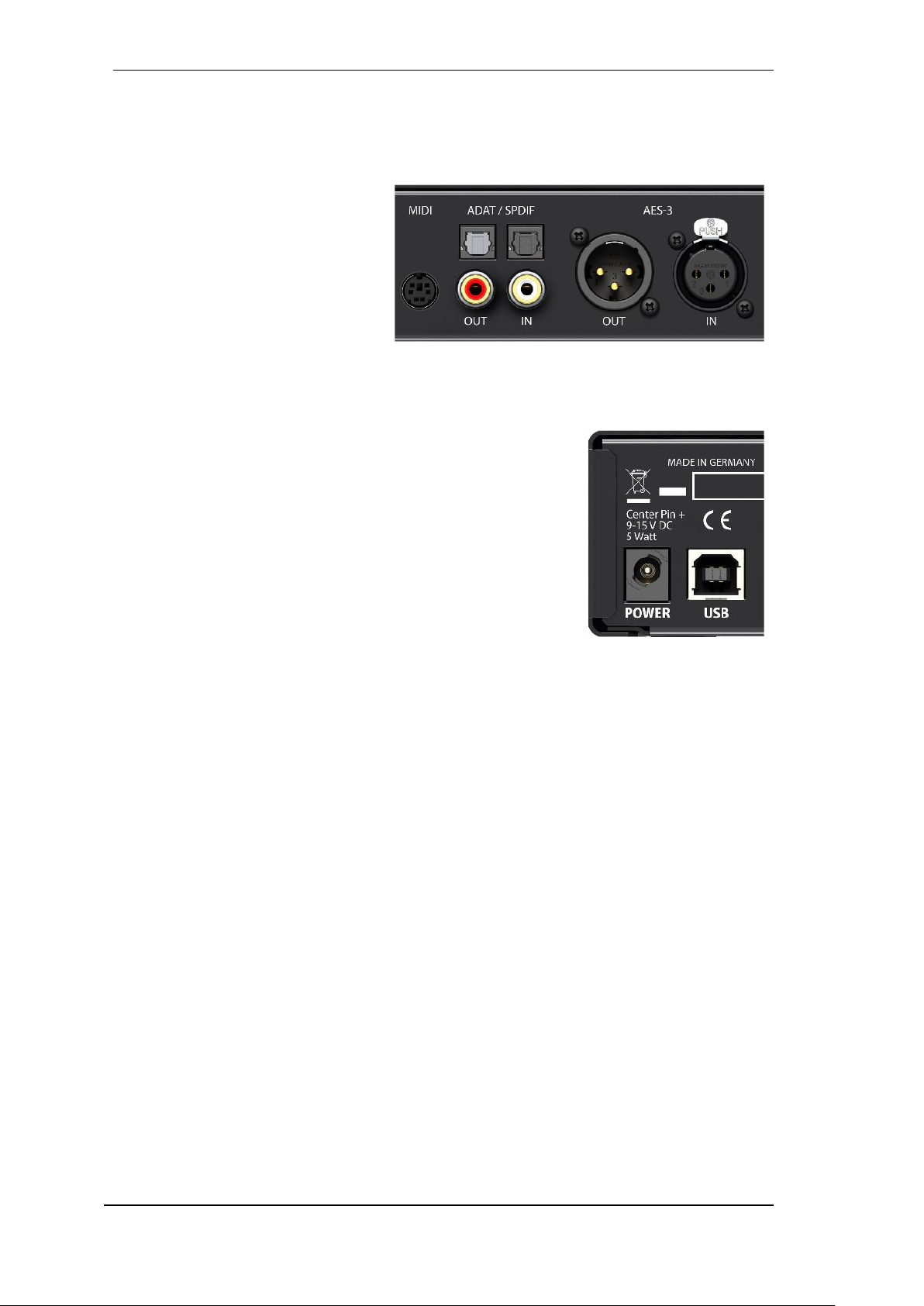
The rear panel of the Digiface AES features 2 analog outputs, AES I/O, SPDIF I/O coaxial and
optical, a connector for the included MIDI breakout cable, USB and the power socket.
Balanced Line Level Outputs. 2 balanced analog outputs via XLR male.
AES/EBU. Digital input and output via
XLR male/female.
SPDIF coaxial. Cinch-Buchse für
SPDIF I/O, kompatibel zu AES/EBU.
ADAT/SPDIF I/O. TOSLINK. Standard
ADAT optical port, 8 channels. Can also
be used as optical SPDIF input and output, if set up accordingly in the Settings
dialog.
MIDI I/O. Two 5-pin DIN connectors provide MIDI input and output.
USB 2.0. USB socket for connection to the computer. Compatible to
USB 3.0.
Kensington Lock. For securing the device via Kensington-compat-
ible solutions.
Power. Serves to unload the computer’s power supply or to ensure
power delivery in case it is not sufficient or fails on the computer side.
In principle, the device also works without a power supply (USB buspowered).
The included hi-performance switch mode power supply operates in the range of 100V to 240V
AC at highest power efficiency. It is short-circuit-proof, has an integrated line filter, is fully regulated against voltage fluctuations, suppresses mains interference, and offers hum-free operation.
It supplies 12 V DC at up to 2 A with the center pin + and outer pin GND.
The connector at the power supply and the socket at the unit come with a turn to lock feature.
When inserting the connector make sure the little wings are aligned correctly so that the
connector is fully inserted. Then turn the connector so that it is locked and can no longer be
removed. If not fully inserted the connection will be loose and cause power loss when the cable
is moved.
User's Guide Digiface AES © RME
11
5.2 Quick Start
After the driver installation (chapter 6 / 13) connect the front inputs with the analog signal source.
The input sensitivity of the rear inputs can be changed in TotalMix (Input Channel Settings), assuring the highest signal to noise ratio will be achieved. Also try to achieve an optimum input level
by adjusting the source itself. Raise the source’s output level until the peak level meters in To-
talMix reach about –3 dB.
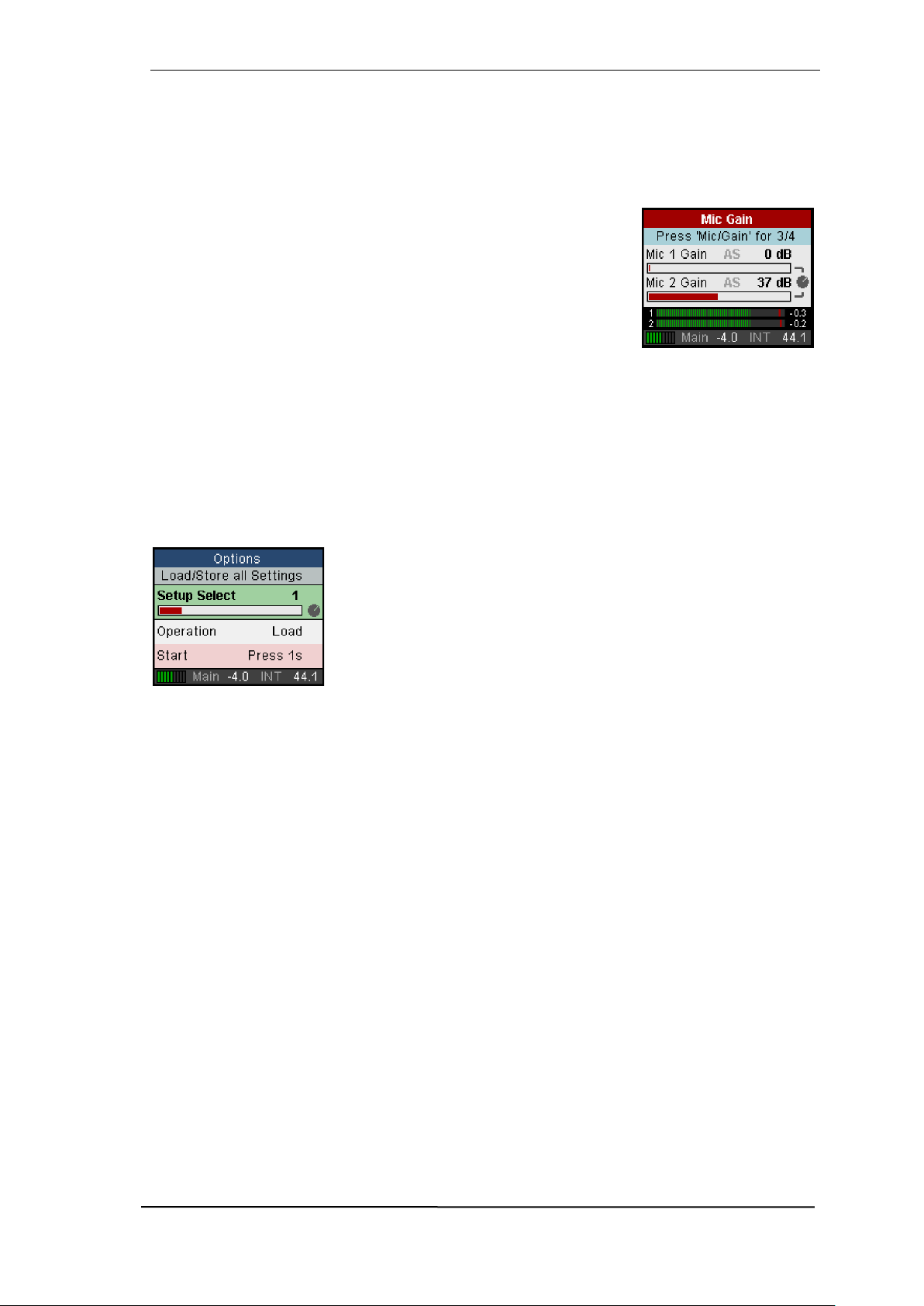
The signal level of the front inputs can also be optimized directly at the
Digiface AES. The key MIC/GAIN gives direct access to this setting,
which is then controlled by the encoder VALUE.
After connecting digital sources, check the clocking via the Settings
dialog and adjust it if necessary.
The digital outputs of the Digiface AES provide AES/EBU, SPDIF coaxial, SPDIF optical and
ADAT optical at the respective ports.
On the analog playback side (the DA side), a coarse adjustment of the analog output level at the
rear jacks is again available in TotalMix (Output Channel Settings, Level), or the Channel Settings
directly at the device. The big encoder VALUE controls the Main Out volume (default: Line Out
1/2).
The output signal of channels 7/8, Phones, can also be controlled directly from the VALUE encoder. Push VALUE to change between Main and Phones control.
The Digiface AES can store and load its current state in 6 different
memory slots, called Setups (SETUP/REV, Options, Load/Store all
Settings). With this, the Digiface AES can be used stand-alone after
setting it up accordingly, replacing lots of dedicated devices (see chapter 24).
In online mode some settings are greyed out, as these should be changed only at the computer,
in the Settings dialog or in TotalMix FX. These include the choice of sample rate and the mix
settings.
5.3 Menu and Navigation
The Digiface AES has a simple and clear menu structure, for fast and efficient operation directly
at the device. In most cases, however, all settings will be done via the Settings dialog and TotalMix
FX of the host computer. The operation on the device is typically limited to a direct adjustment of
the monitoring volume (loudspeaker and headphones) and the microphone gain. In stand-alone
mode, all settings are available directly on the device.
Navigation through the menus of the display and control of the settings is done via four quick
select buttons and a rotary encoder with push function.
Default in the display is the Global Level Meter screen, which shows the current signal levels for
all I/Os. By pressing the encoder knob VALUE for half a second, only the analog I/Os (Analog
Level Meter screen) are displayed, which makes the level display larger and thus easier to read.

12
User's Guide Digiface AES © RME
The Global and Analog Level Meter Screen on the far right also
shows:
The current sample rate
Clock mode and Lock/Sync status of inputs AES, SPDIF and
ADAT. With activated SRC the field turns blue.
MIDI I/O activity by two yellow dots
USB and Class Compliant mode active (CC)
Current output of the volume setting, dB value to it
DSP meter, shows the load of the DSP by activated FX
Turning the knob displays the volume screen of the currently selected output. Pressing the knob toggles the display between Main
Out (Analog Out 1/2, XLR) and Phones (TRS front). At the bottom
right, the current selection and dB value of the Volume setting is
shown, so it is visible even when the Volume screen is not active.
The title bar shows the currently selected output and the assigned
channels (Default Main is Line Out, Phones is fixed to Line Out
7/8).
The quick select buttons MIC/GAIN, USER, CHAN/MIX and SETUP are described in chapter
22.2.
Navigation
The Digiface AES has a simple and fast 1-button operation.
Pressing the VALUE encoder switches between adjusting the parameter and moving horizontally through the menu to moving vertically through the menu. Here is an example: the USER key shall
mute the rear line output instead of switching between the meter
screens (default).
Press the SETUP key. The Options menu appears. The cursor is
in the second line and has the button symbol. Turning the encoder
switches horizontally between the pages Clock, Hardware/Diag-
nosis, Load/Store all Settings and Control Room. After selecting
Hardware/Diagnosis press the encoder knob. The knob symbol
changes to double arrows. By turning the encoder, the cursor now
moves vertically through the menu.
Scroll down to User Key. Press the encoder so that the button
symbol appears. Select the desired function Main Mute by turning
the knob. Quickly exit the menu by pressing the SETUP button
twice. Otherwise the menu will automatically switch to the Global
Level Meter screen after 90 seconds without any user input.

User's Guide Digiface AES © RME
13
5.4 Overview Menu Structure

14
User's Guide Digiface AES © RME
5.5 Special Options
In the menu SETUP - Options - Hardware/Diagnosis there are some additional setting options
which are not described elsewhere in this manual.
Lock Keys. OFF, KEYS, ALL. Press SETUP key for 2 seconds to unlock.
Remap Keys. OFF, ON. Allows assigning 17 different functions/actions to the four quick select
buttons on the device. The configuration is done in the following four entries:
MIC/GAIN, USER, CHAN/MIX, SETUP. Available functions/actions:
Meter, Setup 1-6, DIM, Recall, Mute Enable, Main Mono, Main Mute, Main Out EQ, Main Out Low
Cut, Phones Mute, Phones EQ, Phones Low Cut.
The original function of the key on the device, calling up the menu, is still possible by pressing the
key on the device for a longer time (0.5 s).
Level Meters. All, Main. All shows all channels. Main removes
the ADAT channels from the screen. Same function as pressing the VALUE encoder for half a second.
Scroll Type. cw up, cw down. Allows changing the scroll direction when turning the encoder.

User's Guide Digiface AES © RME
15
User's Guide
Digiface AES
Installation and Operation – Windows
16
User's Guide Digiface AES © RME
6. Hardware, Driver and Firmware Installation
6.1 Hardware and Driver Installation
To simplify installation it is recommended to first install the drivers before the unit is connected to
the computer. But it will also work the other way round.
RME is constantly improving the drivers. Please download the latest drivers from the RME website. Driver version 4.30 or higher is available via http://rme.to/downloads. Unzip the downloaded file and start the driver installation with rmeinstaller.exe.
Start rmeinstaller.exe and follow the instructions of the installer. After installation connect computer and Digiface AES using a USB 2 cable. Windows detects the new hardware as Digiface
AES and installs the drivers automatically.
After a reboot, the icons of TotalMix FX and Settings dialog appear in
the notification area. If not a click on the chevron leads to the settings
that control the icon display.
Driver Updates do not require to remove the existing drivers. Simply install the new driver over
the existing one.
6.2 De-Installing the Drivers
A de-installation of the driver files is not necessary – and not supported by Windows anyway.
Thanks to full Plug & Play support, the driver files will not be loaded after the hardware has been
removed. If desired these files can then be deleted manually.
Unfortunately Windows Plug & Play methods do not cover the additional autorun entries of TotalMix, the Settings dialog, and the registration of the ASIO driver. Those entries can be removed
from the registry through a software de-installation request. This request can be found (like all deinstallation entries) in Control Panel, Software. Click on the entry 'RME MADIface'.
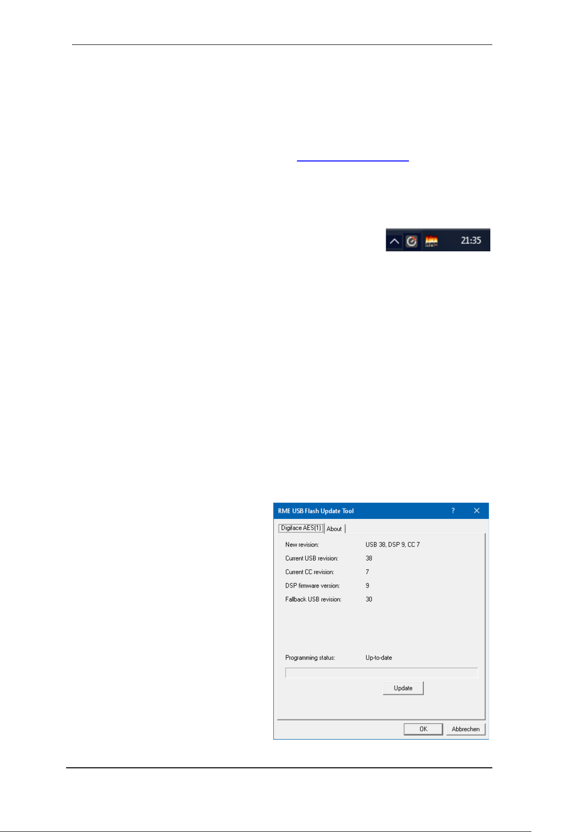
6.3 Firmware Update
The Flash Update Tool updates the firmware of the Digiface AES to the latest version. It requires
an already installed driver.
Start the program fut_usb.exe. The Flash
Update Tool displays the current revision of
the Digiface firmware, and whether it needs
an update or not. If so, then simply press the
'Update' button. A progress bar will indicate
when the flash process is finished (Verify
Ok).
After the update the unit needs to be reset.
This is done by powering down the unit for a
few seconds. A reboot of the computer is not
necessary.
When the update unexpectedly fails (status:
failure), the unit's Safety BIOS will be used
from the next boot on, the unit stays fully
functional. The flash process should then be
tried again.
User's Guide Digiface AES © RME
17
7. Configuring the Digiface – Settings Dialog
7.1 General
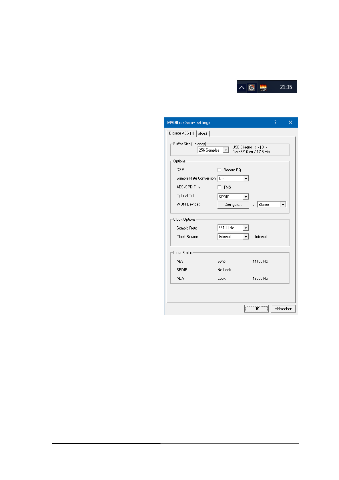
Configuration of the Digiface AES is done via its own settings dialog. The panel Settings can be
opened by clicking on the fire or hammer symbol in the Task Bar's system tray.
The mixer of the Digiface AES, TotalMix FX, can be opened by clicking
on the button symbol in the Task Bar's system tray
The hardware of the Digiface AES offers a number of helpful practical functions and options to
suit many different requirements. The 'Settings' dialog includes options for:
Latency
Operation of the DSP
Configuration of the digital I/Os
Current sample rate
Synchronization behaviour
State of input and output
Any changes made in the Settings dialog
are applied immediately - confirmation
(e.g. by clicking on OK or exiting the dialog) is not required.
However, settings should not be changed
during playback or record if it can be
avoided, as this can cause unwanted
noises. Also, please note that even in
'Stop' mode, several programs keep the
recording and playback devices open,
which means that any new settings might
not be applied immediately.
The tab About includes information
about the current driver and firmware version of the Digiface AES. About offers
four more options:
Lock Registry
Default: off. Checking this option brings
up a dialog to enter a password. Changes
in the Settings dialog are no longer written to the registry. As the settings are always loaded from the registry when starting the computer,
this method provides an easy way to define an initial state of the Digiface AES.
Enable MMCSS for ASIO activates support with higher priority for the ASIO driver. Note: At this
time, activating this option seems to be useful only with the latest Cubase/Nuendo at higher load.
With other software this option can decrease performance. The change becomes active after an
ASIO reset. Therefore it is easy to quickly check which setting works better.
Sort ASIO Devices
Changes the order only of the ASIO channels when using more than one interface.

18
User's Guide Digiface AES © RME
Buffer Size (Latency)
The setting Buffer Size determines the latency between incoming and outgoing ASIO and WDM
data, as well as affecting system stability (see chapter 9.1).
USB Diagnosis indicates USB transmission errors. The display will be reset on any start of a
playback/record. More information can be found in chapter 38.3.
Options
DSP – Record EQ
Switches EQ of all input channels into the recording path. In case Loopback has been activated
the EQ of the Output channel is within the recording path. See also chapter 26.6.
TMS activates the transmission of Channel Status data and Track Marker information on AES
and SPDIF inputs. In case these information are not required the feature should be turned off.
Sample Rate Conversion
The SRC can be connected to one of the digital inputs. Choices are AES, SPDIF (coaxial) and
SPDIF optical. The format ADAT optical is not routed through the SRC in any case. For more
details see chapter 21.5.
Optical Out
The optical TOSLINK output can operate as ADAT or SPDIF output. ADAT: includes channels
ADAT 1 to 8. SPDIF: includes channels SPDIF opt. L/R, in TotalMix ADAT 1/2. In SPDIF mode
Channel Status is fixed to Consumer.
WDM Devices
Reduce the number of WDM devices to the ones really needed to improve performance of the
operating system.
Clock Options
Sample Rate
Sets the currently used sample rate. Offers a central and comfortable way of configuring the sample rate of all WDM devices to the same value, as since Vista the audio software is no longer
allowed to set the sample rate. However, an ASIO program can still set the sample rate by itself.
During record/playback the selection is greyed out, so no change is possible.
Clock Source
The unit can be configured to use its own clock (Internal = Master), or one of the input signals
(AES, SPDIF, Optical = SPDIF optical or ADAT optical). If the selected source isn't available
(Input Status No Lock), the unit will change to the next available one (AutoSync). If none is available then the internal clock is used. The current clock source is displayed to the right.
Input Status
Indicates for inputs AES, SPDIF (coaxial) and Optical (ADAT optical or SPDIF optical) whether
there is a valid signal (Lock, No Lock), or if there is a valid and synchronous signal (Sync). The
third column shows the sample frequency detected by the hardware (coarse recognition, 32 kHz,
44.1 kHz, 48 kHz etc.).

User's Guide Digiface AES © RME
19
7.2 Option WDM Devices
The WDM Devices configuration has one
button to enter the edit dialog, a status display showing the number of currently enabled WDM devices, and a listbox to change
between Stereo or Multi-Channel devices.
The number represents both record and
playback devices, so ‘1’ means one input
and one output device.
The screenshot to the right shows the stereo WDM devices available with the
Digiface AES. Here the first 4 stereo devices have been activated. Any number can
be activated. Also only higher numbered
devices might be active. For example using
the ADAT (1+2) for system based audio
does not require to activate preceeding devices. Only ADAT (1+2) will show up in the
Windows Sound control panel.
The checkbox All to the right allows for a
quick check/uncheck of all devices.
The screenshot to the left shows the multichannel WDM devices available with the
Digiface AES after selecting ‘Multi-Channel’
in the WDM Devices listbox and hitting
WDM Configure. In this example the devices ADAT (1-8) is active.
Using a multi-channel WDM device allows
for the use of multi-channel playback with
specialized software as well as Surround
sound from DVD or Blu-Ray player software.
Please note that configuring the WDM device to a specific surround mode in the control panel Sound requires the device to have
the Speaker property. See next page.
Again the checkbox All to the right allows for
a quick check/uncheck of all devices.

20
User's Guide Digiface AES © RME
Changing to the tab Speaker presents a list
of all currently activated WDM devices. Any
of these can now get the Speaker property.
Please note that defining more than one
device as Speaker usually makes no
sense, and the speakers also don’t get
numbered or renamed in Windows, so it is
impossible to find out which one is which.
After leaving the dialog with OK the WDM
devices are reloaded so Windows sees
their new properties. You can now assign
any surround mode, from stereo to 7.1, in
the Windows Sound control panel by selecting the playback device and clicking the
Configure button.

User's Guide Digiface AES © RME
21
8. Operation and Usage
8.1 Playback
In the audio application being used, Digiface AES must be selected as output device. This can
often be found in the Options, Preferences or Settings menus under Playback Device, Audio De-
vices, Audio etc.
WDM playback devices are not available if the number of WDM devices is set to 0 in the
Settings dialog.
We recommend switching all system sounds off (via >Control Panel /Sounds<). Although the
Digiface AES comes with extensive support for system audio, setting it to be the Default Device
for playback could cause problems when working with ASIO.
Increasing the number and/or size of audio buffers may prevent the audio signal from breaking
up, but also increases latency i.e. output is delayed. For synchronized playback of audio and MIDI
(or similar), be sure to activate the checkbox ‘Get position from audio driver’.
Note: Since Windows Vista the audio application can no longer control the sample rate under
WDM. Therefore the driver of the Digiface AES includes a way to set the sample rate globally for
all WDM devices within the Settings dialog, see chapter 7.1.
8.2 DVD-Playback (AC-3/DTS)
Popular DVD software players can send their audio data stream to any AC-3/DTS capable receiver via the Digiface AES SPDIF output.
The sample rate must be set to 48 kHz in the Digiface AES Settings dialog, or the software
will only playback the down-mixed analog signal via SPDIF.
In some cases an Digiface AES output device has to be selected in >Control Panel / Sound /
Playback< and be set as Default for the software to recognize it.
The DVD software's audio properties now show the options 'SPDIF Out' or similar. When selecting
it, the software will transfer the non-decoded digital multichannel data stream to the Digiface.
Note: This 'SPDIF' signal sounds like chopped noise at highest level. Try to avoid mixing and
routing the signal to your loudspeakers, as they might get damaged.
Multichannel
DVD software player can also operate as software decoder, sending a DVD's multichannel data
stream directly to the analog outputs of the Digiface AES. For this to work select the WDM play-
back device ’Loudspeaker’ of the Digiface AES in >Control Panel/ Sound/ Playback < as Default.
The playback software’s audio properties now list several multichannel modes. If one of these is
selected, the software sends the decoded analog multichannel data to the Digiface AES. TotalMix
can then be used to play back via any desired output channels.
!
!

22
User's Guide Digiface AES © RME
8.3 Channel Count under WDM
The Digiface’ ADAT optical ports support sample rates of up to 192 kHz. For this to work singlechannel data is spread to two or four ADAT channels using the Sample Multiplexing technique.
This reduces the number of available ADAT channels from 8 to 4 or 2 per ADAT port.
Whenever the Digiface changes into Double Speed (88.2/96 kHz) or Quad Speed mode
(176.4/192 kHz) all devices no longer available vanish automatically.
WDM Stereo device
Double Speed
Quad Speed
Digiface Analog (1+2)
Digiface Analog (1+2)
Digiface Analog (1+2)
Digiface Analog (3+4)*
Digiface Analog (3+4)*
Digiface Analog (3+4)*
Digiface SPDIF
Digiface SPDIF
Digiface SPDIF
Digiface AES
Digiface AES
Digiface AES
Digiface ADAT 1 (1+2)
Digiface ADAT 1 (1+2)
Digiface ADAT 1 (1+2)
Digiface ADAT 1 (3+4)
Digiface ADAT 1 (3+4)
Digiface ADAT 1 (3+4)
Digiface ADAT 1 (5+6)
Digiface ADAT 1 (5+6)
Digiface ADAT 1 (5+6)
Digiface ADAT 1 (7+8)
Digiface ADAT 1 (7+8)
Digiface ADAT 1 (7+8)
* Playback only.
8.4 Multi-client Operation
RME audio interfaces support multi-client operation. Several programs can be used at the same
time. The formats ASIO and WDM can even be used on the same playback channels simultaneously. But as WDM uses a real-time sample rate conversion (ASIO does not), all active ASIO
software has to use the same sample rate.
However, a better overview is maintained by using the channels exclusively. This is no limitation
at all, because TotalMix allows for any output routing, and therefore a playback of multiple software on the same hardware outputs.
Inputs can be used from an unlimited number of WDM and ASIO software at the same time, as
the driver simply sends the data to all applications simultaneously.
RME's sophisticated tool DIGICheck is an exception to this rule. It operates like an ASIO host,
using a special technique to access playback channels directly. Therefore DIGICheck is able to
analyse and display playback data from any software, no matter which format it uses.

User's Guide Digiface AES © RME
23
8.5 Analog Recording
For recordings via the analog inputs the corresponding record device has to be chosen (Digiface
AES Analog (1+2)).
The input sensitivity of the inputs can be changed with adjustable gain in TotalMix (Input Channel
Settings, Gain), assuring the highest signal to noise ratio will be achieved. A further optimization
can be achieved by adjusting the source itself. Raise the source’s output level until the peak level
meters in TotalMix reach about –3 dB.
The level of the front-side analog inputs can also be optimized directly at the Digiface AES by the
key Mic/Gain and the encoder. The multi-colour level meters shown on the display additionally
provide useful information about the current level state.
Further information is found in chapter 19.
It often makes sense to monitor the input signal or send it directly to the output. This can be done
at zero latency using TotalMix FX (see chapter 24).
An automated control of real-time monitoring can be achieved by Steinberg’s ASIO protocol with
RME’s ASIO drivers and all ASIO 2.0 compatible programs. When 'ASIO Direct Monitoring' has
been switched on, the input signal is routed in real-time to the output whenever a recording is
started (punch-in).
8.6 Digital Recording
Unlike analog soundcards which produce empty wave files (or noise) when no input signal is
present, digital interfaces always need a valid input signal to start recording.
Taking this into account, RME added a comprehensive I/O signal status display to the
Digiface AES, showing sample frequency, lock
and sync status for every input, and several
status fields in the unit’s display.
The sample frequency shown in the fields
Clock Mode and Input Status of the Settings
dialog is useful as a quick display of the current configuration of the unit and the connected external equipment. If no sample frequency is recognized, it will read ‘No Lock’.
This way, configuring any suitable audio application for digital recording is simple. After selecting
the correct input, Digiface AES displays the current sample frequency. This parameter can then
be changed in the application’s audio attributes (or similar) dialog.

24
User's Guide Digiface AES © RME
8.7 Clock Modes - Synchronization
In the digital world, all devices must be either Master (clock source) or Slave (clock receiver).
Whenever several devices are linked within a system, there must always be a single master clock.
A digital system can only have one master! If the Digiface’s clock mode is set to 'Master', all
other devices must be set to ‘Slave’.
The Digiface AES utilizes a very user-friendly, intelligent clock control, called AutoSync. In AutoSync mode, the system constantly scans the digital input for a valid signal. If any valid signal is
found, the Digiface switches from the internal quartz (Clock Source – Current Internal) to a clock
extracted from the input signal (Clock Source – Current AES, SPDIF, ADAT). The difference to a
usual slave mode is that whenever the clock reference fails, the system will automatically use its
internal clock and operate in clock mode Master.
AutoSync guarantees that record and record-while-play will always work correctly. In certain
cases however, AutoSync may cause feedback in the digital carrier, so synchronization breaks
down. To remedy this, switch the Digiface clock mode to ‘Internal’.
RME’s exclusive SyncCheck technology enables an easy to use check and display of the current
clock status. SyncCheck indicates whether there is a valid signal (Lock, No Lock) for each input
(AES, SPDIF coaxial, ADAT/SPDIF optical), or if there is a valid and synchronous signal (Sync).
See chapter 38.1.
Via Clock Source a preferred input can be defined. As long as the Digiface sees a valid signal
there, this input will be designated as the sync source, otherwise the other inputs will be scanned
in turn. If none of the inputs are receiving a valid signal, the Digiface automatically switches clock
mode to ‘Internal’.
Under WDM the Digiface will (has to) set the
sample rate. Therefore the error shown to the
right can occur. An AES, SPDIF or ADAT
signal with a sample rate of 48 kHz is used as
sync source, but Windows audio had been set
to 44100 Hz before.
The red color of the text label signals the error condition, and prompts the user to set 48000 Hz
manually as sample rate.
Under ASIO the audio software sets the sample rate, so that such an error will usually not happen
– but it can too. In slave mode the external sample rate has priority. Feeding 44.1 kHz will prevent
the ASIO software to set 48 kHz – obviously, as the only way to do so would be to enter a different
clock mode (Master/Internal).
In practice, SyncCheck provides the user with an easy way of checking whether all digital devices
connected to the system are properly configured. With SyncCheck, finally anyone can master this
common source of error, previously one of the most complex issues in the digital studio world.
!

User's Guide Digiface AES © RME
25
9. Operation under ASIO
9.1 General
Start the ASIO software and select ASIO MADIface USB as the audio I/O device or the ASIO
audio driver.
The Digiface AES supports ASIO Direct Monitoring (ADM).
The Digiface AES MIDI I/O can be used with both MME MIDI and DirectMusic MIDI.
9.2 Channel Count under ASIO
At a sample rate of 88.2 or 96 kHz, the ADAT optical input and outputs operate in S/MUX mode,
so the number of available channels per port is reduced from 8 to 4. At a sample rate of 176.4
and 192 kHz, the ADAT optical input and output operates in S/MUX4 mode, so the number of
available channels is limited to 2.
Note: When changing the sample rate range between Single, Double and Quad Speed the number of channels presented from the ASIO driver will change too. This may require a reset of the
I/O list in the audio software.
Single Speed
Double Speed
Quad Speed
Digiface Analog 1 to 4
Digiface Analog 1 to 4
Digiface Analog 1 to 4
Digiface SPDIF 1 / 2
Digiface SPDIF 1 / 2
Digiface SPDIF 1 / 2
Digiface AES 1 / 2
Digiface AES 1 / 2
Digiface AES 1 / 2
Digiface ADAT 1 to 8
Digiface ADAT 1 to 4
Digiface ADAT 1 to 2

26
User's Guide Digiface AES © RME
9.3 Known Problems
If a computer does not provide sufficient CPU-power, and/or sufficient USB or PCI bus transfer
rates, and/or sufficient PCIe-bus transfer rates, then drop outs, crackling and noise will appear.
Raising the buffer size in the Settings dialog of the Digiface AES helps in most cases. It is also
recommended to deactivate all PlugIns to verify that these are not the reason for such effects.
Further information is found in chapter 40.3.
Another common source of trouble is incorrect synchronization. ASIO does not support asynchronous operation, which means that the input and output signals not only have to use the same
sample frequency, but also have to be in sync. All devices connected to the Digiface AES must
be properly configured for full duplex operation. As long as SyncCheck (in the Settings dialog)
only displays Lock instead of Sync, the devices have not been set up properly.
The same applies when using more than one Digiface AES - they all have to be in sync. Else a
periodically repeated noise will be heard.
RME devices support ASIO Direct Monitoring (ADM). Please note that not all programs support
ADM completely or error-free. The most often reported problem is the wrong behaviour of panorama in a stereo channel. Also try to avoid setting the TotalMix FX hardware outputs (third row)
to mono mode. This will most likely break ADM compatibility.
In case of a drift between audio and MIDI, or in case of a fixed deviation (MIDI notes placed close
before or behind the correct position), the settings in Cubase/Nuendo have to be changed. At the
time of print the option 'Use System Timestamp' should be activated. The Digiface AES supports
both MME MIDI and DirectMusic MIDI. It depends on the used application which one will work
better.
10. Using more than one Digiface AES
The driver supports up to three Digiface AES or a combination of up to three supported interfaces.
All units have to be in sync, i.e. have to receive valid sync information (either via word clock or by
using AutoSync and feeding synchronized signals).
If one of the Digifaces is set to clock mode Master, all others have to be set to clock mode
AutoSync, and have to be synced from the master, for example by feeding word clock. The
clock modes of all units have to be set up correctly in the Digiface Settings dialog.
If all units are fed with a synchronous clock, i.e. all units show Sync in their Settings dialog,
all channels can be used at once. This is especially easy to handle under ASIO, as the ASIO
driver presents all units as one.
Note: TotalMix is part of the hardware of each Digiface. Up to three mixers are available, but
these are separated and can't interchange data. Therefore a global mixer for all units is not possible.

User's Guide Digiface AES © RME
27
11. DIGICheck Windows
The DIGICheck software is a unique utility developed for testing, measuring and analysing digital
audio streams. Although this Windows software is fairly self-explanatory, it still includes a comprehensive online help. DIGICheck 5.96 operates as multi-client ASIO host, therefore can be used
in parallel to any software, be it WDM or ASIO, with both inputs and outputs (!). The following is
a short summary of the currently available functions:
Level Meter. High precision 24-bit resolution, 2/8/16 channels. Application examples: Peak
level measurement, RMS level measurement, over-detection, phase correlation measurement, dynamic range and signal-to-noise ratios, RMS to peak difference (loudness), long term
peak measurement, input check. Oversampling mode for levels higher than 0 dBFS. Vertical
and horizontal mode. Slow RMS and RLB weighting filter. Supports visualization according to
the K-System.
Hardware Level Meter for Input, Playback and Output. Reference Level Meter freely con-
figurable, causing near zero CPU load, because calculated from the Digiface hardware.
Spectral Analyser. World wide unique 10-, 20- or 30-band display in analog bandpass-filter
technology. 192 kHz-capable!
Vector Audio Scope. World wide unique Goniometer showing the typical afterglow of a oscil-
loscope-tube. Includes Correlation meter and level meter.
Totalyser. Spectral Analyser, Level Meter and Vector Audio Scope in a single window.
Surround Audio Scope. Professional Surround Level Meter with extended correlation analy-
sis, ITU weighting and ITU summing meter.
ITU1770/EBU R128 Meter. For standardized loudness measurements.
Bit Statistics & Noise. Shows the true resolution of audio signals as well as errors and DC
offset. Includes Signal to Noise measurement in dB and dBA, plus DC measurement.
Channel Status Display. Detailed analysis and display of SPDIF and AES/EBU Channel Sta-
tus data.
Global Record. Long-term recording of all channels at lowest system load.
Completely multi-client. Open as many measurement windows as you like, on any channels
and inputs or outputs!
DIGICheck is free but works only with RME interfaces. It is constantly improved and updated. The
latest version is always available on our website www.rme-audio.com, section Downloads /
Software.

28
User's Guide Digiface AES © RME
12. Hotline – Troubleshooting
The newest information can always be found on our website www.rme-audio.com, section FAQ,
Latest Additions.
The 8 ADAT channels don’t show up at the optical output
The optical output has been switched to ‘SPDIF’. The ADAT playback devices are still usable
by routing and mixing them in TotalMix to other outputs.
Playback works, but record doesn’t
Check that there is a valid signal at the input. If so, the current sample frequency is displayed
in the Settings dialog.
Check whether the Digiface AES has been selected as recording device in the audio applica-
tion.
Check whether the sample frequency set in the audio application (‘Recording properties’ or
similar) matches the input signal.
Check that cables/devices have not been connected in a closed loop. If so, set the system’s
clock mode to Master.
Crackle during record or playback
Increase the number and size of buffers in the ‘Settings’ dialog or in the application.
Try different cables (coaxial or optical) to rule out any defects here.
Check that cables/devices have not been connected in a closed loop. If so, set the system’s
clock mode to ‘Master’.
Check the Settings dialog for displayed Errors.
Driver installation and Settings dialog/TotalMix work, but a playback or record is not possible
While recognition and control of the device are low bandwidth applications, playback/record
needs the full transmission performance. Therefore, defective USB cables with limited transmission bandwidth can cause such an error scheme.

User's Guide Digiface AES © RME
29
User's Guide
Digiface AES
Installation and Operation – Mac OS X
30
User's Guide Digiface AES © RME
13. Hardware, Driver and Firmware Installation
13.1 Hardware and Driver Installation
After the Digiface has been connected to the computer and switched on install the drivers matching your current macOS.
RME is constantly improving the drivers. Please download the latest drivers from the RME website
at http://rme.to/download. Unzip the downloaded file and start the driver installation by doubleclicking Fireface USB.pkg.
During driver installation the programs Totalmix (TotalMix FX) and Fireface USB Settings are
copied to the Applications folder. They will automatically start into the dock if a Digiface AES is
connected. A reboot of the computer is not required.
Driver Updates do not require to remove the existing drivers. Simply install the new driver over
the existing one.
13.2 De-installing the Drivers
In case of problems the driver files can be deleted manually by dragging them to the trash bin:
/Applications/Fireface USB Settings
/Applications/Totalmix
/System/Library/Extensions/FirefaceUSB.kext
/Users/username/Library/Preferences/de.rme-audio.TotalmixFX.plist
/Users/username/Library/Preferences/de.rme-audio.Fireface_USB_Settings.plist
/Library/LaunchAgents/de.rme-audio.firefaceUSBAgent.plist
Under the latest Mac OS X the User/Library folder is not visible in the Finder. To unhide it start
Finder, click on the menu item Go. Hold down the option (alt) key, then click on Library.
With the latest DriverKit drivers, the whole driver is the RME Settings app found in Applications.
Deleting this app also removes the driver from the system.
13.3 Firmware Update
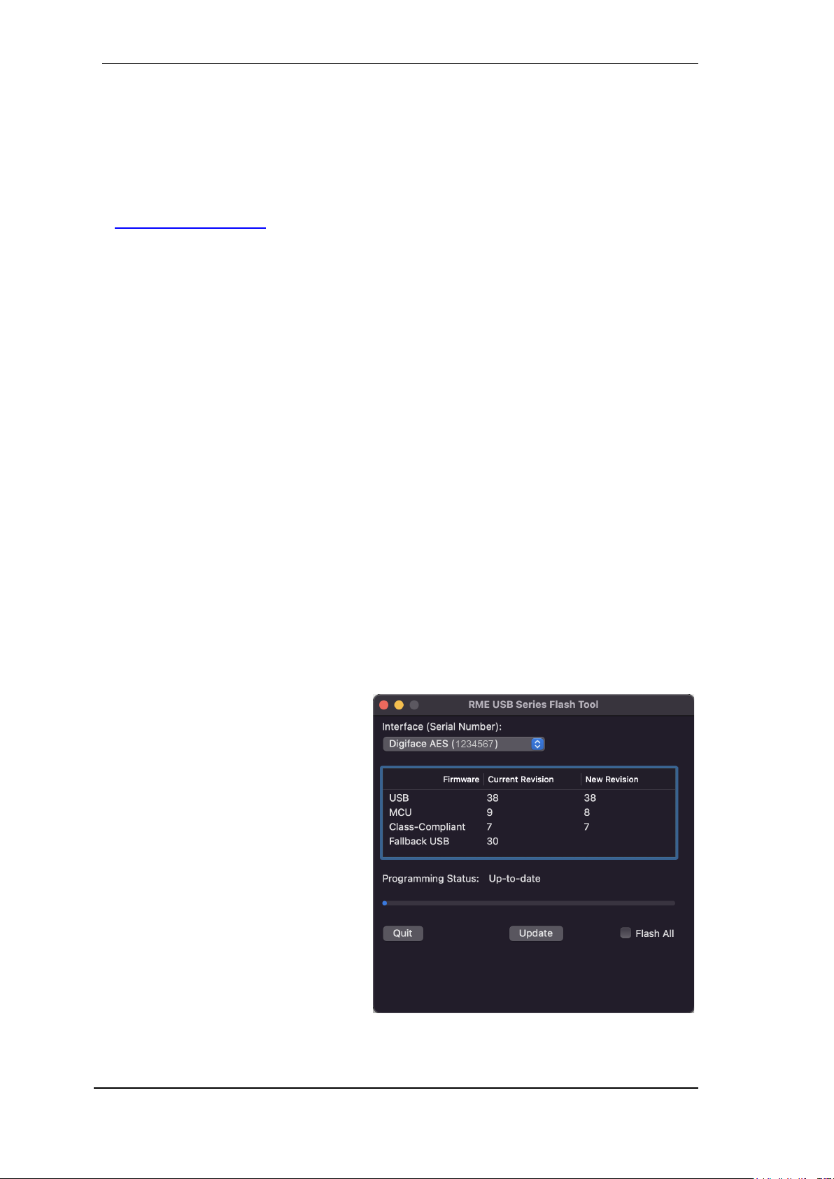
The app RME USB Series Flash Tool up-
dates the firmware of the Digiface AES to
the latest version. It requires an already installed Thunderbolt or USB driver.
After start the tool displays the current revision of the Digiface AES firmware, and
whether it needs an update or not. If so,
simply press the 'Update' button. A progress bar will indicate when the flash process is finished (Verify Ok).
After the update the Digiface AES needs to
be reset. This is done by powering down
the Digiface for a few seconds. A reboot of
the computer is not necessary.
User's Guide Digiface AES © RME
31
To speed up the process of flashing the app only updates older parts of the firmware. Using the
option Flash All a complete update can be forced.
When the update fails (status: failure), the unit's second BIOS will be used from the next cold boot
on (Secure BIOS Technology). Therefore the unit stays fully functional. The flash process should
then be tried again on a different computer.
14. Configuring the Digiface AES
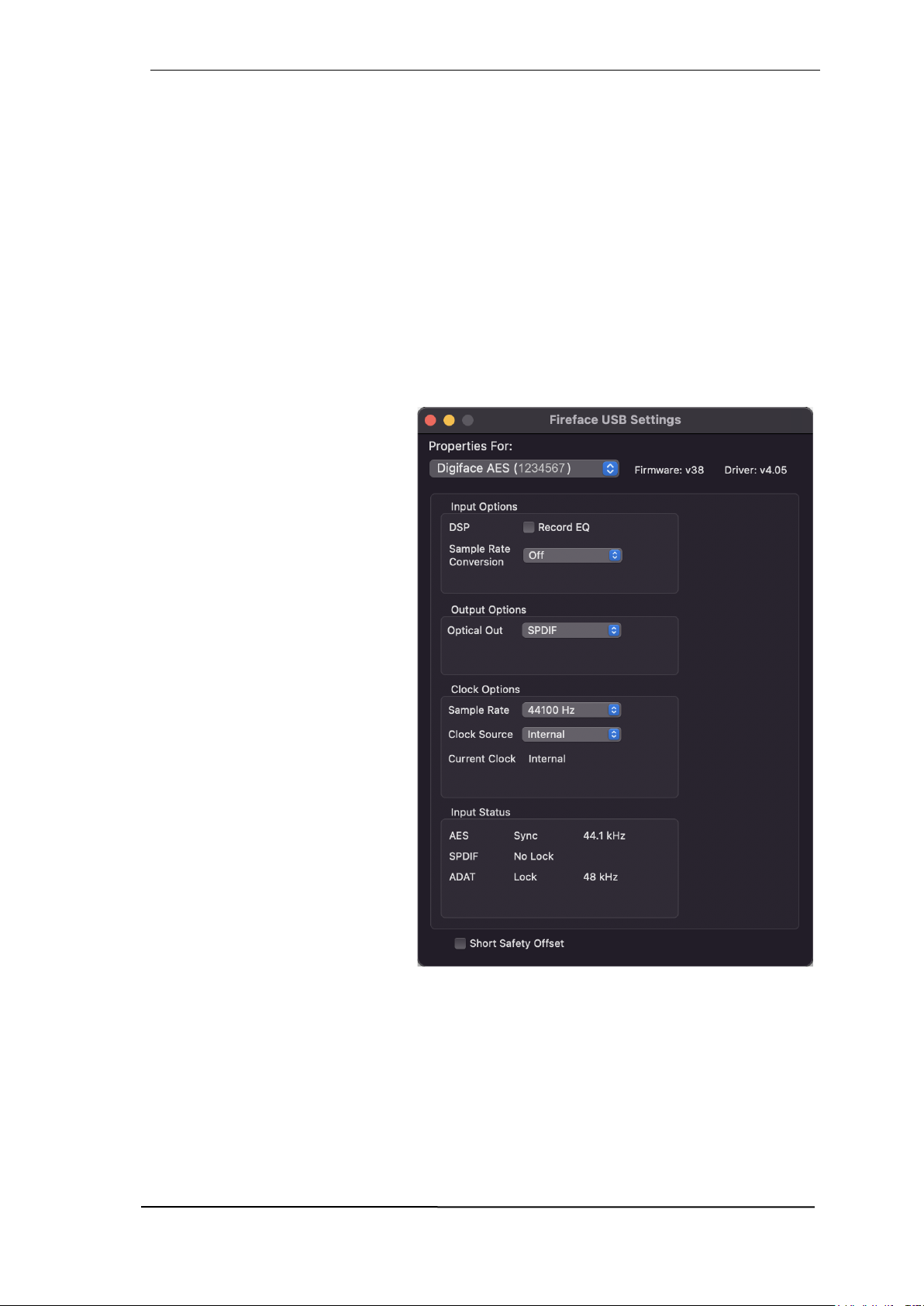
14.1 Settings Dialog
Configuring the Digiface is done via its own settings dialog in the app Fireface USB Settings.
The mixer app of the Digiface AES is called TotalMix FX.
The Digiface’s hardware offers a number of helpful, practical functions and options to suit many
different requirements. The following is available in the 'Settings' dialog:
Operation of the DSP
Configuration of digital I/Os
Current sample rate
Synchronization behaviour
State of input and output
Any changes performed in the Settings dialog are applied immediately
- confirmation (e.g. by exiting the dialog) is not required.
However, settings should not be
changed during playback or record if
it can be avoided, as this can cause
unwanted noises.
Use the drop down menu Properties
For to select the unit to be configured.
On the right of it the current firmware
and driver version of the Digiface
AES is shown.
Input Options
DSP – Record EQ
Switches EQ all input channels into
the recording path. In case Loopback
has been activated the EQ of the
Output channel is within the recording path. See also chapter 26.6.
Sample Rate Conversion
The SRC can be connected to one of the digital inputs. Choices are AES, SPDIF (coaxial) and
SPDIF optical. The format ADAT optical is not routed through the SRC in any case. For more
details see chapter 21.5.
Output Options
Optical Out
The optical TOSLINK output can operate as ADAT or SPDIF output.

32
User's Guide Digiface AES © RME
Clock Options
Sample Rate
Used to set the current sample rate. This is the same setting as in the Audio MIDI Setup, just
added here for your convenience.
Clock Source
The unit can be configured to use its own clock (Internal = Master), or one of the input signals
(AES, SPDIF, Optical = SPDIF optical or ADAT optical). If the selected source isn't available
(Input Status No Lock), the unit will change to the next available one (AutoSync). If none is available then the internal clock is used. The current clock source is displayed to the right.
Input Status
Indicates for inputs AES, SPDIF (coaxial) and Optical (ADAT optical or SPDIF optical) whether
there is a valid signal (Lock, No Lock), or if there is a valid and synchronous signal (Sync). The
third column shows the sample frequency detected by the hardware (coarse recognition, 32 kHz,
44.1 kHz, 48 kHz etc.).
Short Safety Offset
Reduces overall latency by using smaller Safety Offsets (12 samples instead of 24 samples).
Change is performed in real-time. Smaller Safety Offsets might cause clicks and dropouts.
14.2 Clock Modes - Synchronization
In the digital world, all devices must be either Master (clock source) or Slave (clock receiver).
Whenever several devices are linked in a system, there must always be a single master clock.
A digital system can only have one master! If the Digiface’s clock mode is set to 'Master', all
other devices must be set to ‘Slave’.
The Digiface AES utilizes a very user-friendly, intelligent clock control, called AutoSync. In AutoSync mode, the system constantly scans the digital input for a valid signal. If any valid signal is
found, the Digiface switches from the internal quartz (Clock Mode – Current Internal) to a clock
extracted from the input signal (Clock Mode – Current AES, SPDIF, ADAT). The difference to a
usual slave mode is that whenever the clock reference fails, the system will automatically use its
internal clock and operate in clock mode Master.
AutoSync guarantees that record and record-while-play will always work correctly. In certain
cases however, AutoSync may cause feedback in the digital carrier, so synchronization breaks
down. To solve this problem switch the Digiface clock mode to ‘Internal’.
RME’s exclusive SyncCheck technology enables an easy to use check and display of the current
clock status. SyncCheck indicates whether there is a valid signal (Lock, No Lock) for each input
(AES, SPDIF, ADAT, or if there is a valid and synchronous signal (Sync). In the field Clock Mode
the clock reference is shown. See chapter 38.1.
Via Clock Source a preferred input can be defined. As long as the Digiface sees a valid signal
there, this input will be designated as the sync source, otherwise the other inputs will be scanned
in turn. If none of the inputs are receiving a valid signal, the Digiface automatically switches clock
mode to ‘Internal’.
In some situations changing the clock mode can not be avoided. Example: An ADAT recorder is
connected to the ADAT input (ADAT immediately becomes the AutoSync source) and a CD player
is connected to the AES input. Try recording a few samples from the CD and you will be disappointed - few CD players can be synchronized. The samples will inevitably be corrupted, because
the signal from the CD player is read with the clock from the ADAT. In this case the Clock Source
should be temporarily set to AES.
!

User's Guide Digiface AES © RME
33
In practice, SyncCheck provides the user with an easy way of checking whether all digital devices
connected to the system are properly configured. With SyncCheck, finally anyone can master this
common source of error, previously one of the most complex issues in the digital studio world.
15. Mac OS X FAQ
15.1 MIDI doesn't work
In some cases the applications do not show the MIDI port. The reason for this is usually visible
within the Audio MIDI Setup. It displays no RME MIDI device, or the device is greyed out and
therefore inactive. Mostly, removing the greyed out device and searching for MIDI devices again
will solve the problem.
The Digiface’ MIDI is class compliant. Therefore it comes without a driver. OS X recognizes it as
MIDI device and will be using it with the driver included in the operating system.
15.2 Repairing Disk Permissions
Repairing permission can solve problems with the installation process - plus many others. To do
this, launch Disk Utility located in Utilities. Select your system drive in the drive/volume list to
the left. The First Aid tab to the right now allows you to check and repair disk permissions.
15.3 Supported Sample Rates
RME's Mac OS X driver supports all sampling frequencies provided by the hardware. This includes 32 kHz and 64 kHz, and even 128 kHz, 176.4 kHz and 192 kHz.
But not any software will support all the hardware's sample rates. The hardware's capabilities can
easily be verified in the Audio MIDI Setup. Select Audio devices under Properties of: and
choose the Digiface. A click on Format will list the supported sample frequencies.
15.4 Channel Count under Core Audio
At a sample rate of 88.2 or 96 kHz, the ADAT optical input and outputs operate in S/MUX mode,
so the number of available channels per port is reduced from 8 to 4. At a sample rate of 176.4
and 192 kHz, the ADAT optical input and output operates in S/MUX4 mode, so the number of
available channels is limited to 2.
It is not possible to change the number of Core Audio channels without a reboot of the computer.
Therefore whenever the Digiface changes into Double Speed (88.2/96 kHz) or Quad Speed mode
(176.4/192 kHz) all channels stay present, but become partly inactive.

34
User's Guide Digiface AES © RME
15.5 Various Information
Programs that don't support card or channel selection will use the device chosen as Input and
Output in the System Preferences – Sound panel.
Via Launchpad – Other – Audio MIDI Setup the Digiface can be configured for the system wide
usage in more detail.
Programs that don't support channel selection will always use channels 1/2, the first stereo pair.
To access other inputs, use the following workaround with TotalMix: route the desired input signal
to output channels 1/2. In the channel settings of outputs 1/2 activate Loopback. Result: the desired input signal is now available at input channel 1/2, without further delay/latency.
Use Configure Speakers to freely configure the stereo or multichannel playback to any available
channels.
16. Using more than one Digiface
OS X supports the usage of more than one audio device within an audio software. This is done
via the Core Audio function Aggregate Devices, which allows to combine several devices into
one.
The current driver supports up to three Digiface AES. All units have to be in sync, i.e. have to
receive valid sync information either via word clock or by feeding synchronized signals.
If one of the Digifaces is set to clock mode Master, all others have to be set to clock mode
Slave, and have to be synced from the master, for example by feeding word clock. The clock
modes of all units have to be set up correctly in the Digiface Settings dialog.
If all units are fed with a synchronous clock, i.e. all units show Sync in their Settings dialog,
all channels can be used at once.
Please be aware that operating more than one Digiface AES may cause resource problems on
the computer side.
Note: TotalMix is part of the Digiface hardware. Up to three mixers are available, but these are
separated and can't interchange data. Therefore a global mixer for all units is not possible.

User's Guide Digiface AES © RME
35
17. DIGICheck NG Mac
The DIGICheck software is a unique utility developed for testing, measuring and analysing digital
audio streams. Although the software is fairly self-explanatory, it still includes a comprehensive
online help. DIGICheck NG 0.90 operates in parallel to any software, showing all input data. The
following is a short summary of the currently available functions:
Level Meter. High precision 24-bit resolution, 2/8/16 channels. Application examples: Peak
level measurement, RMS level measurement, over-detection, phase correlation measurement, dynamic range and signal-to-noise ratios, RMS to peak difference (loudness), long term
peak measurement, input check. Oversampling mode for levels higher than 0 dBFS. Vertical
and horizontal mode. Slow RMS and RLB weighting filter. Supports visualization according to
the K-System.
Hardware Level Meter for Input, Playback and Output. Reference Level Meter freely con-
figurable, causing near zero CPU load, because calculated from the Digiface hardware.
Spectral Analyser. World wide unique 10-, 20- or 30-band display in analog bandpass filter
technology. 192 kHz-capable!
Vector Audio Scope. World wide unique Goniometer showing the typical afterglow of a oscil-
loscope-tube. Includes Correlation meter and level meter.
Totalyser. Spectral Analyser, Level Meter and Vector Audio Scope in a single window.
Surround Audio Scope. Professional Surround Level Meter with extended correlation analy-
sis, ITU weighting and ITU summing meter.
ITU1770/EBU R128 Meter. For standardized loudness measurements.
Bit Statistics & Noise. Shows the true resolution of audio signals as well as errors and DC
offset. Includes Signal to Noise measurement in dB and dBA, plus DC measurement.
Completely multi-client. Open as many measurement windows as you like, on any channels
and inputs or outputs!
DIGICheck is constantly updated. The latest version is always available on our website www.rme-
audio.com, section Downloads / Software.

36
User's Guide Digiface AES © RME
18. Hotline – Troubleshooting
The newest information can always be found on our website www.rme-audio.com, section FAQ,
latest Additions.
The unit and drivers have been installed correctly, but playback does not work:
Has Digiface been selected as current playback device in the audio application?
The 8 ADAT channels don’t seem to work
The optical output ADAT has been switched to SPDIF. The ADAT playback devices are still
usable by routing and mixing them in TotalMix to other outputs.
Playback works, but record doesn’t:
Check that there is a valid signal at the input. If so, the current sample frequency is displayed
in the Settings dialog.
Check whether the Digiface AES has been selected as recording device in the audio applica-
tion.
Check whether the sample frequency set in the audio application (‘Recording properties’ or
similar) matches the input signal.
Check that cables/devices have not been connected in a closed loop. If so, set the system’s
clock mode to ‘Master’.
Crackle during record or playback:
Increase the number and size of buffers in the application.
Try different cables (coaxial or optical) to rule out any defects here.
Check that cables/devices have not been connected in a closed loop. If so, set the system’s
clock mode to ‘Master’.
Check the Settings dialog for displayed Errors.
Possible causes for a Digiface not working
The USB cable is not, or not correctly inserted into the socket
Driver installation and Settings dialog/TotalMix work, but a playback or record is not possible
While recognition and control of the device are low bandwidth applications, playback/record
needs the full transmission performance. Therefore, defective USB cables with limited transmission bandwidth can cause such an error scheme.

User's Guide Digiface AES © RME
37
User's Guide
Digiface AES
Inputs and Outputs

38
User's Guide Digiface AES © RME
19. Analog Inputs
The two balanced microphone inputs of the Digiface AES offer a digitally controlled gain of 75 dB,
adjustable in steps of 1 dB. The soft switching, hi-current Phantom power (48 Volt), switchable
per channel, provides a professional handling of condensor mics. Up to a level of +18 dBu the
front XLR input can also be used as balanced and unbalanced Line input.
The TRS jacks of the two combo jacks are free of phantom power and fully compatible to unbalanced (mono jack) sources. They have a fixed level attenuation of 6 dB. The maximum input level
is therefore +24 dBu, balanced and unbalanced.
Channels 5/6 feature an automatic overload protection. AutoSet tries to keep a headroom of 6
dB. Levels higher than -6 dBFS will permanently reduce the gain. To check set the channels to a
high gain and apply an input signal. The button will quickly rotate back to a gain that is appropriate.
While with extreme overloads distortion will occur for the fraction of a second before the level is
set correctly, AutoSet works quite well in real-world applications and prevents distorted recordings
reliably.
Using stereo channels AutoSet operates ganged. AutoSet can be
activated in TM FX or directly at the unit in the channel settings.
As soon as AutoSet reduces the gain the label AS, shown in the
front display, changes its colour from black to blue.
20. Analog Outputs
20.1 Line / XLR
The short circuit protected, low impedance line outputs of channels 5/6 are available as male XLR
jacks on the back of the unit.
Two discrete hardware output levels are available, set in TotalMix Output Channel Settings, Level:
+19 dBu and +4 dBu, both @ 0 dBFS.
The electronic driver circuit of the XLR outputs does not operate servo-balanced! When connecting unbalanced equipment, make sure pin 3 of the XLR output is not connected. A connection to ground will cause higher THD (distortion)!
20.2 Headphones / Line Out
Channels 7/8 of the Digiface are available on the front as 1/4" TRS jack. These channels use the
same converters as the Line outputs, therefore offer the same technical data.
Two hardware-based reference levels are available (set in TotalMix Output Channel Settings,
Level, High or Low). High equals +13 dBu @ 0 dBFS, Low +7 dBu @ 0 dBFS (6 dB lower output
level).
These outputs are low impedance types (5 Ohms), perfectly suited for headphone use.
Setting the output level, i.e. the monitoring volume, is done – besides the pre-setting High/Low -
via TotalMix (Hardware Output, Phones) or directly at the unit via the encoder. Changing the
monitoring volume is therefore very easy and quickly done.
In case the Phones output should operate as line outputs, an adapter TRS plug to RCA phono
plugs, or TRS plug to TS plugs is required. See chapter 39.2 for details.
!

User's Guide Digiface AES © RME
39
20.3 DC-coupled Outputs (CV/Gate)
The analog outputs of the Digface AES are DC-coupled. DC coupling has the obvious advantage
of allowing the output to operate level-linearly down to 0 Hz. Even at extremely low bass (16 Hz)
phase shifts are avoided. DC-coupled inputs are rare, especially for power amplifiers, so a possible DC offset of a playback normally does not cause issues.
In order to realize the outputs stable and reliable (robust) as DC-coupled, the circuitry was designed for low DC-offsets and sufficient overvoltage protection.
To be able to generate DC is quite useful in measurement technology, also in connection with
audio. However, DC coupling is especially desirable in combination with electronic sound generators (synthesizers). These have an input that can control the pitch as well as other functions via
a DC voltage. Control Voltage, short CV, often also CV/Gate (gate determines tone on or off), CV
Filter etc. is mostly based on the voltage range 0 to +5 Volt. If an audio interface can output such
DC voltages then synthesizers can be controlled via suitable software and the analog outputs of
the audio interface.
The balanced outputs 1/2 (XLR, balanced) are less suitable for this application, since pin 3 of the
XLR output must not be connected to ground, but which is the case with many cables. In addition,
the main monitor output is no longer available. It therefore makes more sense to use the headphone output for such purposes.
Polarity - Phase
Since the outputs (of course) have a correct polarity, and TotalMix fully supports DC (via fader
and level meter), a positive voltage appears at the analog output when a digital positive DC is
played. The amount of voltage can be measured accurately and directly with any cheap multimeter.
Negative output voltages should be avoided, because they could theoretically lead to defects
in the CV input. Even if the software used generates only positive signals, a simple phase
inversion in TotalMix can invert the signal so that a negative voltage is send out.
Voltage Ranges
Line Out 1-6, unbalanced (mono jack), unloaded:
+19 dBu: +4.75 V, +13 dBu: ++2.37 V, +4 dBu: +0.85 V
Phones 7/8, unbalanced, unloaded:
High (+13 dBu): +4.75 V, Low (+4 dBu): +1.7 V
Note: The level meters in TotalMix show DC 3 dB higher due to its factory default setting. This
can be changed by disabling the Settings - Level Meters - RMS +3 dB option in TotalMix FX.
!

40
User's Guide Digiface AES © RME
21. Digital Connections
21.1 AES/EBU
The Digiface AES’s provides one AES/EBU input and output via XLR. Connection is accomplished using balanced cables with XLR plugs. Input and output are transformer-balanced and
ground-free. The incoming channel status is ignored.
AES/EBU (and SPDIF) can contain Emphasis information. Audio signals with Emphasis have a
high frequency boost, requiring high frequency attenuation on playback.
An Emphasis indication gets lost as there exists no standardized interface on computers to
handle this information!
Operation as second SPDIF I/O
Thanks to a highly sensitive input stage SPDIF
coaxial can be fed too by using a simple cable
adapter RCA/XLR. To achieve this, pins 2 and 3
of a male XLR plug are connected individually to
the two pins of a RCA plug. The cable shielding is
only connected to pin 1 of the XLR - not to the
RCA plug.
Using the cable adapter XLR/RCA described above, devices with coaxial SPDIF interface can be
connected to the AES output of the Digiface AES as well. Note that most consumer equipment
with phono (SPDIF) inputs will only accept signals having a Channel Status Consumer. In such
cases the above adapter cable will not work.
21.2 SPDIF (Coaxial, Optical)
The Digiface AES has up to three SPDIF inputs and outputs: coaxial, optical and AES can be
used simultaneously, with different audio signals. Note that at least two sources have to be synchronous, as the unit includes only one sample rate converter.
The SPDIF coaxial input accepts SPDIF and AES/EBU, Consumer as well as Professional format.
To receive signals in AES/EBU format, an adapter
cable is required. Pins 2 and 3 of a female XLR
plug are connected individually to the two pins of
a phono plug. The cable shielding is connected to
pin 1 of the XLR and the ground contact of the
phono plug.
The optical input automatically switches to SPDIF operation when such a signal is detected. The
audio information is then shown in TotalMix on the first two ADAT channels ADAT 1/2, which are
channels 7 and 8.
SPDIF coaxial Output
Apart from the audio data itself, digital signals in SPDIF or AES/EBU format have a header containing channel status information. False channel status is a common cause of malfunction. The
Digiface AES ignores the received header and creates a totally new one for the output signal.
SPDIF optical output
To send out SPDIF from the optical output, select the option Optical Out – SPDIF in the Settings
dialog. The output signal in TotalMix has to be present on the ADAT channels 1/2.
In SPDIF mode the optical output is fixed to Consumer status.
!

User's Guide Digiface AES © RME
41
21.3 ADAT
The ADAT optical input of the Digiface AES is fully compatible with all ADAT optical outputs.
RME's unsurpassed Bitclock PLL prevents clicks and drop outs even in extreme varipitch operation, and guarantees a fast and low jitter lock to the digital input signal. A usual TOSLINK cable
is sufficient for connection.
ADAT In
Interface for receiving an ADAT signal. Carries the channels 1 to 8. When receiving a Double
Speed signal, this input carries the channels 1 to 4, at Quad Speed the channels 1 and 2.
The format ADAT is recognized automatically. Some devices send an identifier at 96 kHz, so that
the clock can adapt automatically. However, such an identifier does not exist for 192 kHz, here
the correct sample rate must be set manually in the Settings dialog or the ASIO DAW.
ADAT Out
Interface for sending an ADAT signal. Transmits channels 1 to 8. When sending a Double Speed
signal, this port carries channels 1 to 4, at Quad Speed the channels 1 and 2. Can also be used
as a 2-channel SPDIF optical output.
To output SPDIF via the optical output, select Optical Out - ADAT in the Settings dialog.
21.4 MIDI
Digiface AES offers one MIDI I/O via a breakout cable with two 5-pin DIN sockets. The MIDI ports
are added to the system by the driver. Using MIDI capable software, these ports can be accessed
under the name Digiface AES MIDI Port.
The MIDI ports support multi-client operation. A MIDI input signal can be received from several
programs at the same time. Even the MIDI output can be used by multiple programs simultaneously. However, due to the limited bandwidth of MIDI, this kind of application will often show
various problems.
Note: The MIDI input indicator displays any kind of MIDI activity, including MIDI Clock, MTC and
Active Sensing. The latter is sent by most keyboards every 0.3 seconds.

42
User's Guide Digiface AES © RME
21.5 Sample Rate Converter (SRC)
The Digiface AES has three digital inputs that can be used simultaneously: AES, SPDIF coaxial
and SPDIF optical. SPDIF as a consumer format is often not synchronizable, a simultaneous use
of the inputs is not possible.
A stereo Sample Rate Converter (SRC) included in the Digiface AES solves this problem. An
SRC not only allows real-time conversion of the sample rate, but also clock decoupling. The highquality converter works practically lossless and with low latency (2.5 ms), there are no audible
artifacts or noise during the conversion.
Via the Settings dialog, or directly in the device
menu (only in CC and stand-alone mode), the
SRC is assigned to one of the three inputs. Reference is the current clock (display Current).
This can be either Internal or one of the three
digital input signals.
The SRC offers a maximum conversion rate of 1:7 or 7:1, respectively. Thus, 192 kHz can be
converted to any sample rate down to 32 kHz, and vice versa.
However, an SRC serves not only the conversion of the sample frequency, but also the clock
decoupling, i.e. adjustment of two equal sample rates to full synchronicity. By means of SRC any
non-synchronizable device (CD player, DAT etc.) can be used in combination as if it were synchronizable. The SRC decouples the input clock from the reference clock, and thus allows the
merging of different clock sources without any clicks or dropouts.
A jittery input signal might degrade the quality of the sample rate conversion. The Digiface AES
therefore has a second SteadyClock exclusively for the current SRC input signal to make the
sample rate conversion process as reliable and transparent as possible.
Like the Digiface AES, the SRC only supports Single Wire mode.
The SRC is not available to the optical input’s 8-channel ADAT format.
Typical applications for the SRC are real-time sample rate conversion, and clock decoupling of
non-synchronizable sources. But an SRC is also good for digital sources in other respects, because it guarantees continuous clocking without disturbances. An example from practice: DAT
tapes often show little formatting errors between the various recorded takes. There can also be
tiny snippets with other sample rates between the recordings. An SRC reliably converts this patchwork into a continuous, permanently valid data stream with a fixed sample rate. Even if there are
unformatted spots on the tape, or the DAT is being stopped or switched off, the Digiface AES
receives a constant signal (which in this case does not contain audio information).

User's Guide Digiface AES © RME
43
User's Guide
Digiface AES
Stand-Alone Operation

44
User's Guide Digiface AES © RME
22. Operation and Usage
22.1 General
Using the rotary encoder, the four buttons and the clear colour display the Digiface AES can be
configured and set up completely at the device. Additionally internal memory allows for the permanent storage of six different states of the unit. Therefore the Digiface AES is able to operate
fully stand-alone, without any connected computer. In stand-alone operation it can transform into
totally different devices by the simple click of a button. Furthermore TotalMix FX, and with this the
application examples shown below, can also be controlled via MIDI, see chapter 27.6, Stand-
Alone MIDI Control.
22.2 Settings at the Unit
The Digiface AES has a simple menu structure, depending on the button pressed.
MIC/GAIN. First push brings up the Mic.Gain, second push returns to the meter screen. Used to
set Gain and AutoSet for analog inputs, channels 5 and 6.
USER. Activates the command stored under Remap Keys, see chapter 5.5.
CHAN/MIX. First push brings up the Channel menu, second push the Mix to menu, third push
returns to the meter screen. In the Channel menu, the encoder is used to select the input and
output to be set, then the function to be set. These are Settings, Parametric EQ and Low Cut.
The Mix to menu gives access to the whole submix functionality, mix destination and source. A
source can be modified in mix level and panorama.
SETUP. The encoder is used to select various options. The Options menu has the subpages
Load/Store all Settings, Clock, Hardware/Diagnosis and Control Room.
22.3 Store / Load Setups at the Unit
After hitting the key SETUP/REV, the encoder gives access to the subpage Load/Store all Settings. First select the preferred memory slot, then the desired process (load or store). The
load/store process is completed by pushing the encoder for more than one second.
The Digiface AES has six memory slots for free usage. Three fixed slots offer convenient and
quick reset and configuration of the unit:
Factory. Sets the unit into factory default state.
AD/DA. Loads a configuration of an AES from/to Analog converter.
Clear Mix. Performs a Total Reset of TotalMix FX.
22.4 Storing Setups from the Computer
Setups can be loaded into the unit from the computer. As the Setups are usually generated at the
computer the final step of transmission offers a convenient workflow. In TotalMix FX use Options
/ Store current state into device to select the desired storage place (Setup) within the unit.

User's Guide Digiface AES © RME
45
23. Examples
23.1 2-Channel AD/DA-Converter
TotalMix' super-flexible routing functions make it easy to turn the Digiface AES into a 2-channel
AD/DA converter, analog from/to ADAT.
It’s easy to build up the respective setup. For a clean start perform a Total Reset from the Options
menu. Then select the ADAT Output 1/2 in the third row, and pull up the fader of the Analog input
1/2 in the first row.
Now do the same for the analog outputs: select Analog Output 1/2 and move the fader of ADAT
Input 1/2 to 0 dB, and so on. An additional monitoring of all or selected I/Os can be easily set up
for any digital output, or as analog mixdown on the the phones output.
23.2 2-Channel Mic Preamp
Use TotalMix to route the two microphone inputs directly to the analog outputs. This turns the
Digiface AES into a 2-channel microphone preamp. The AD- and DA-conversion will cause a
small delay of the signals of around 0.1 ms (at 192 kHz, see chapter 38.2). But this is nothing to
worry about, as it is the same delay that would be caused by changing the microphone's position
by about 3.3 centimeter (1.3 inches).
23.3 Monitor Mixer
TotalMix allows ANY configuration of all I/Os of the Digiface. For example, set up the device as
monitor mixer for 2 analog signals, 8 digital via ADAT, 2 via AES and 2 via SPDIF. Additionally,
TotalMix lets you set up ANY submixes, so all existing outputs can be used for different and
independent monitorings of the input signals. The perfect headphone monitor mixer!
23.4 Digital Format Converter (Multitool)
As TotalMix allows for any routing of the input signals, the Digiface AES can be used as ADAT to
AES converter, ADAT to two SPDIF (splitter), AES to ADAT converter, and universal 1 to 3 distributor and format converter. Additionally, the SRC is available, which turns the Digiface AES
into a multi-format converter for AES, SPDIF coaxial and SPDIF optical, especially since all output
formats are available simultaneously.
23.5 Analog / Digital Routing Matrix
The Matrix in TotalMix enables you to route and link all inputs and outputs completely freely. All
the above functionalities are even available simultaneously, can be mixed and combined in many
ways. Simply said: the Digiface AES is a perfect analog/digital routing matrix!
23.6 Jitter Remover
Thanks to SteadyClock FS the Digiface AES can also serve as an extreme jitter destroyer. Any
digital signal is radically dejittered after passing the device through the SteadyClock 1 Hz filter.
This also applies in combination with the use of the SRC.

46
User's Guide Digiface AES © RME

User's Guide Digiface AES © RME
47
User's Guide
Digiface AES
TotalMix FX

48
User's Guide Digiface AES © RME
24. Routing and Monitoring
24.1 Overview
The Digiface AES includes a powerful digital real-time mixer, the Digiface AES mixer, based on
RME’s unique, sample-rate independent TotalMix technology. It allows for practically unlimited
mixing and routing operations, with all inputs and playback channels simultaneously, to any hardware outputs. TotalMix FX adds 3-band parametric Equalizer and Low Cut.
Here are some typical applications for TotalMix:
Setting up delay-free submixes (headphone mixes). The Digiface AES allows for up to 8 fully
independent stereo submixes. On an analog mixing desk, this would equal 16 Aux sends.
Unlimited routing of inputs and outputs (free utilisation, patchbay functionality).
Distributing signals to several outputs simultaneously. TotalMix offers state-of-the-art splitter
and distributor functions.
Simultaneous playback of different programs via a single stereo output. The ASIO multi-client
driver supports the usage of several programs at the same time. If this happens on different
playback channels TotalMix provides the means to mix and monitor these on a single stereo
output.
Mixing of the input signal to the playback signal (complete ASIO Direct Monitoring). RME is
not only the pioneer of ADM, but also offers the most complete implementation of the ADM
functions.
Integration of external devices. Use TotalMix to insert external effects devices, be it in the
playback or in the record path. Depending on the current application, the functionality equals
insert or effects send and effects return, for example as used during real-time monitoring when
adding some reverb to the vocals.
Every single input channel, playback channel and hardware output features a Peak and RMS
level meter, calculated in hardware. These level displays are very useful to determine the presence and routing destinations of the audio signals.
For a better understanding of the TotalMix mixer you should know the following:
As shown in the block diagram (next page), the record signal usually stays un-altered. TotalMix
does not reside within the record path, and does not change the record level or the audio data
to be recorded (exceptions: DSP - Record EQ and Loopback mode).
The hardware input signal can be passed on as often as desired, even with different levels.
This is a big difference to conventional mixing desks, where the channel fader always controls
the level for all routing destinations simultaneously.
The level meters of input and playback channels are connected pre-fader, to be able to visually
monitor where a signal is currently present. The level meters of the hardware outputs are
connected post-fader, thus displaying the actual output level.

User's Guide Digiface AES © RME
49

50
User's Guide Digiface AES © RME
24.2 The User Interface
The visual design of the TotalMix mixer is a result of its capability to route hardware inputs and
software playback channels to any hardware output. The Digiface AES has 14 input channels, 16
software playback channels, and 16 hardware output channels:
TotalMix can be used in the above view (View Options 2 Rows). However, the default is a vertical
alignment in three rows as known from an Inline desk, so that the row Software Playback equals
the Tape Return of a real mixing desk:
Top row: Hardware inputs. The level shown is that of the
input signal, i.e. fader independent. Via fader and routing
menu, any input channel can be routed and mixed to any
hardware output (bottom row).
Middle row: Playback channels (playback tracks of the
audio software). Via fader and routing menu, any playback channel can be routed and mixed to any hardware
output (bottom row).
Bottom row: Hardware outputs. Here, the total level of
the output can be adjusted. This may be the level of connected loudspeakers, or the level of any submix.
Usage in mode Submix View (Default)
Click on the Hardware Output channel in the third row where the audio signal is supposed to show
up. This channel turns brighter, means it is selected as current submix. Now move the faders up
from all sources – these are the input and playback channels, in the first and second row. That’s
it. The input (monitoring) and playback (DAW software) audio signals are now available at that
very output, which can be verified immediately from the level meters reacting accordingly.
The following chapters explain step by step all functions of the user interface.

User's Guide Digiface AES © RME
51
25.3 The Channels
A single channel can be switched between mono and stereo mode. The mode is set in the channel
settings.
Channel name. The name field is the preferred place to select a channel by a mouse click. A
double click opens a dialog to assign a different name. The original name will be shown when
activating the option Names in the View Options.
Panorama. Routes the input signal freely to the left and right routing destination
(lower label, see below). The level reduction in center position is -3 dB.
Mute and Solo. Input channels and playback channels each have a mute and solo
button.
Numerical level display. Shows the current RMS or Peak level, updated twice per
second. OVR means overload. The setting Peak/RMS is changed in the View Options.
Level meter. The meter shows both peak values (zero attack, 1 sample is enough
for a full scale display) by means of a yellow line, and mathematically correct RMS
values by means of a green bar. The RMS display has a relatively slow time constant, so that it shows the average loudness quite well. Overs are shown in red at
the top of the bar. In the Preferences dialog (F2) the Peak Hold time, the over detection and the RMS reference can be set.
Fader. Determines the gain/level of the signal routed to the current routing destination (lower
label). Please note that this fader is not the fader of the channel, but only the fader of the current
routing. Compared to a standard mixing desk TotalMix does not have a channel fader, but only
Aux Sends, as many as there are hardware outputs. Therefore TotalMix can create as many
different Submixes as there are hardware outputs. This concept is understood best in the Submix
View, but more on that later.
Below the fader the Gain is shown in a numerical display field,
according to the current fader position. The fader can be:
dragged with the left mouse button pressed
moved by the mouse wheel
set to 0 dB and −∞ by a double click. The same happens with
a single click plus held down Ctrl key.
adjusted in fine mode by mouse drag and mouse wheel when
holding the Shift key down
A Shift-click on a fader adds the fader to the temporary fader
group. All faders now marked yellow are ganged, and move simultaneously in a relative way. The temporary fader group is deleted
by a click on the F symbol in the upper right of the window.
The arrow symbol at the bottom minimizes the channel width to that of the level meters. Another
click maximizes it again. A mouse click with held Ctrl key causes all channels to the right to enlarge and minimize at once.

52
User's Guide Digiface AES © RME
The lowest field shows the current routing target. A mouse click
opens the routing window to select a routing target. The list shows all
activated routings of the current channel by arrows in front of the
listed entries, the current one is shown in bold letters.
An arrow is only shown with an activated routing. A routing is seen as
activated when audio data is sent. As long as the fader is set to −∞
the current routing will be shown in bold letters, but not have an arrow
in the front.
Trim Gain. After a click on the T-button one channel’s faders are all synchronized. Instead of
changing only a single routing the fader affects all the channel’s active routings. For a better
overview the faders currently not visible are indicated by orange triangles beside the fader path.
When moving the fader the triangles also move to a new position, equalling the invisible faders’
new settings.
Note that the fader button is automatically set to the highest routing gain of all routings so that
best control is offered. The gain (fader knob position) of the currently active routing (the submix
selected in the third row) is shown as white triangle.
Background: TotalMix has no fixed channel fader. In case of the Digiface AES there
are 16 mono Aux sends, shown alternately as single fader within the channel strip.
The high number of Aux sends enables multiple and fully independent routings.
In some cases it is necessary to synchronize the gain changes of these routings. An
example is the Post fader function, where a change of the singer’s volume shall be
performed identical to the volume change of the signal sent to the reverb device, so
that the reverb level keeps its relation to the original signal. Another example is the
signal of a guitar that is routed to different submixes, means hardware outputs, which
gets much too loud during the solo part, and therefore needs to be reduced in volume
on all outputs simultaneously. After a click on the Trim button this can be done easily
and with a perfect overview.
As all channel’s routings change simultaneously when Trim is active, this mode ba-
sically causes the same behaviour as a trim pot within the input channel, affecting
the signal already before the mixer. That’s how this function got its name.
In the View Options / Show the function Trim Gains can be globally switched on and off for all
channels. The global Trim mode is recommended when using TotalMix FX as live mixing desk.
The Context Menu. With a right click on the input, playback and output channels their context
menus provide advanced functionality (these menus are also available in the Matrix, but only
directly on the channel labels). The entries are self-explanatory and automatically adjust to where
the click is performed. On all of these the first entry opens the Channel Layout dialog. The input
channels offer Clear, Copy input, paste the input mix and paste its FX. On a playback channel
Copy, Paste and Clear the playback mix are available. On an output channel Copy and Mirror
functionality for the current submix and copying of the FX settings is offered.

User's Guide Digiface AES © RME
53
24.3.1 Settings
A click on the tool symbol opens the channel’s Settings panel with differing elements, respective
to the channel’s format.
Stereo. Switches the channel to mono or stereo mode.
48V. Only for Mic 1/2. Activates phantom power at the corresponding input. Serves as power
supply for high quality condenser mics. This option should stay off with other sources to prevent
failure by spikes.
PAD. Only for Mic 1/2. Applies -11 dB damping for the XLR input signal.
Also increases the input impedance.
Gain. Only for Mic 1/2. Sets the gain for the four front inputs. The knob can
be adjusted by dragging the mouse or by the mouse wheel. This also
works when the mouse has been moved over the two gain displays. Then
the gain can be changed separately for left and right channel, even when
the channel is in stereo mode.
AutoSet. Only for Mic 1/2. Activates an automatic gain reduction preventing overloads caused by too high gain settings. See chapter 19 for details.
Width. Defines the stereo width. 1.00 equals full stereo, 0.00 mono, -1.00
swapped channels.
MS Proc. Activates M/S processing within the stereo channel. Monaural
information is sent to the left channel, stereo information to the right.
Phase L, Phase R. Inverts the phase of the left or right channel by 180°.
AN1→ 2. Available only in stereo mode of the Mic 1/2 input pair. Copies the signal of input channel
Mic/Line 1 (analog 1) to channel Mic/Line 2 (analog 2). Typical application: A microphone should
be audible on both channels of a stereo recording.
Note: the functions Width, MS Proc, Phase L, Phase R and AN1→ 2 affect all routings of the
respective channel.
The settings of the Hardware Outputs have further options:
Level. Sets the reference levels of the analog outputs. Analog 1/2: +4 dBu,
+13 dBu, +19 dBu. Phones: Low (+7 dBu), High (+13 dBu).
Talkback. Activates this channel as receiver and output of the Talkback
signal. This way Talkback can be sent to any outputs, not only the Phones
in the Control Room section. Another application could be to send a certain
signal to specific outputs by the push of a button.
No Trim. Sometimes channels need to have a fixed routing and level,
which should not be changed in any case. An example is the stereo mixdown for recording of a live show. With No Trim active, the routing to this
output channel is excluded from the Trim Gains function, therefore is not
changed unintentionally.
Loopback. Sends the output data to the driver as record data. The corre-
sponding submix can be recorded then. This channel’s hardware input
sends its data only to TotalMix, no longer to the recording software.

54
User's Guide Digiface AES © RME
Another difference to the input and playback channels is the Cue button instead of Solo. A click
on Cue sends the respective Hardware Output’s audio to the Main Out, or any of the Phones
outputs (option Assign – Cue/PFL to in the Control Room section). With this any hardware output
can be controlled and listened to through the monitoring output very conveniently.
24.3.2 Equalizer
A click on EQ opens the Equalizer panel. It is available in all input and output channels, and
affects all routings of the respective channel (pre fader). The panel includes a low cut and a 3band parametric equalizer which can be activated separately.
EQ. Activated by the EQ button.
Type. Band 1 and 3 can operate in peak (bell) or shelf (shelv-
ing) mode. The middle band is fixed to peak mode. Band 3
can also operate as Hi Cut (low pass filter), especially useful
for LFE and subwoofer purposes.
Gain. All three bands can change their amplification between
+20 dB to -20 dB.
Freq. The center frequency of the filters is adjustable between
20 Hz and 20 kHz. While in peak mode the center frequency
is adjusted, in shelf mode the cut-off point (-3 dB) will be
changed.
Q. The Quality factor of the filter is adjustable from 0.7 (wide)
to 5.0 (narrow).
Lo Cut. Activated by the button Lo Cut. The slope of the high-pass filter is adjustable between 6,
12, 18 and 24 dB per octave. The cut-off point (-3 dB) is adjustable between 20 Hz and 500 Hz.
The frequency graphics give a precise overview of the filter results. Overlapping filters influence
each other. This can be used to achieve more than 20 dB amplitude, or to generate difficult frequency response optimizations.
Note: TotalMix has an internal headroom of 24 dB. Extreme boosts with overlapping filters can
therefore cause an internal overload. In any case such an overload is displayed by the Over LED
of the channel’s level meter.

User's Guide Digiface AES © RME
55
Preset. Settings of the EQ and the Low Cut can
be stored, loaded, and copied between channels at any time. A click on Preset opens a
menu with several entries:
Recall: Presets stored before by the user
can be selected and loaded
Save to: There are 16 storage places
available (EQ Preset 1 to 16)
Import: Loads a previously stored TM EQ
file (.tmeq)
Export: Stores the current state as TM EQ
file (.tmeq)
Factory: Includes 14 examples for the cre-
ative use of Low Cut and Equalizer
Reset: Resets the Low Cut and EQ to have
zero influence (Gain 0 dB)
Rename: The EQ Presets 1 to 16 can be renamed. The changes will be shown in both lists
Recall and Save to.
Notes on the EQ Presets
Copy between channels: The EQ Preset menu of all channels is identical. If an EQ setup is
stored via Save to on one of the 16 storage places, it is then also available in any other channel
via Recall.
Copy between Snapshots: The Presets are not saved in Snapshots, therefore do not change
when a different Snapshot is loaded. Presets are saved in Workspaces and also loaded with
these.
Copy between Workspaces: is done by the export and import function of the Preset menu.
Important and useful Presets should always be saved as TM EQ file, so that they can not get lost
even on accidental overwrite.
Factory Presets: loaded like all Presets the settings of both Low Cut and EQ simultaneously.
The current state, On or Off, is neither saved nor activated on load. With this a preset can be
loaded anytime, but will not become active before the user decides to switch the EQ and/or LC
on – except they had been active already before the load process. For this reason some Factory
Presets have special names. For example Telephone (LC+EQ) will sound much better when the
LC has been activated additionally to the EQ, as the LC is set to an unusual high frequency of
500 Hz here.

56
User's Guide Digiface AES © RME
24.4 Section Control Room
In the section Control Room the menu Assign defines the Main
Out which is used for listening in the studio. For this output the
functions Dim, Recall, Mono, Talkback, External In and Mute FX
are automatically applied. At the unit the VOLUME knob follows
this assignment.
Additionally the channel will be shifted from the Hardware Outputs into the Control Room section, and renamed Main. The
same happens when assigning Main Out B or the Phones. The
original name can be displayed by the function Names in the
View Options menu at any time.
Phones 1 to 4 will have Dim (set in Settings) and a special routing applied when Talkback is activated. Putting them beside the
Main Out increases the overview within the output section
greatly.
Dim. The volume will be reduced by the amount set in the Settings dialog (F3).
Recall. Sets the gain value defined in the Settings dialog.
Speaker B. Switches playback from Main Out to Main Out B. The faders of the channels Main
and Speaker B can be ganged via Link.
Mono. Mixes left and right channel. Useful to check for mono compatibility and phase problems.
Talkback. A click on this button will dim all signals on the Phones outputs by an amount set up
in the Settings of TotalMix FX. At the same time the control room's microphone signal (source
defined in Settings) is sent to the Phones. The microphone level is adjusted with the channel's
input fader.
External Input. Switches Main monitoring from the mix bus to the stereo
input defined in the Settings dialog (F3). The relative volume of the stereo
signal is adjusted there as well.
Assign. Allows to define the Main Out, Main Out B (Speaker B), and up
to four Phones outs.
The output for the Cue signal, which is usually Main,
can also be set to one of four Phones outputs. The
setting Cue/PFL to also controls the PFL monitoring.

User's Guide Digiface AES © RME
57
24.5 The Control Strip
The Control Strip on the right side is a fixed element. It combines different functions that are either
required globally, or constantly used, and therefore should not be hidden in a menu. It can still be
hidden via the top menu Window – Hide Control Strip.
The areas described in the following chapters can be minimized by a click on the arrow in their
title bar.
Device selection. Select the unit to be controlled in case more than one is
installed on the computer.
FX - DSP Meter. Shows the DSP load caused by activated EQ and Low Cut.
The DSP of the Digiface AES has been designed so that an overload cannot
occur. The display therefore is for information purposes only.
Undo / Redo. With the unlimited Undo and Redo changes of the mix can be
undone and redone, at any time. Undo/Redo does not cover graphical changes
(window size, position, channels wide/narrow etc.), and also no changes to the
Presets. The accidental overwrite of an EQ Preset can not be made undone.
Undo/Redo also operates across Workspaces. Therefore a completely differently set up mixer view can be loaded via Workspace, and with a single click on
Undo the previous internal mixer state is returned – but the new mixer view
stays.
Global Mute - Solo - Fader.
Mute. Global Mute operates in a pre fader style, muting all currently activated routings of the
channel. As soon as any Mute button is pressed, the Mute Master button lights up in the Control
Strip area. With this button all selected mutes can be switched off and on again. One can comfortably set up a mute group or activate and deactivate several mute buttons simultaneously.
Solo. As soon as any Solo button is pressed, the Solo Master button lights up in the Control Strip
area. With this button all selected Solos are switched off and on again. Solo operates as Solo-inPlace, post fader style, as known from common mixing desks. A typical limitation for mixing desks,
Solo working only globally and only for the Main Out, does not exist in TotalMix. Solo is always
activated for the current submix only.
Fader. A Shift-click on a fader adds the fader to the temporary fader group. All faders now
marked yellow are ganged, and move simultaneously in a relative way. The temporary fader group
is deleted by a click on the F symbol.
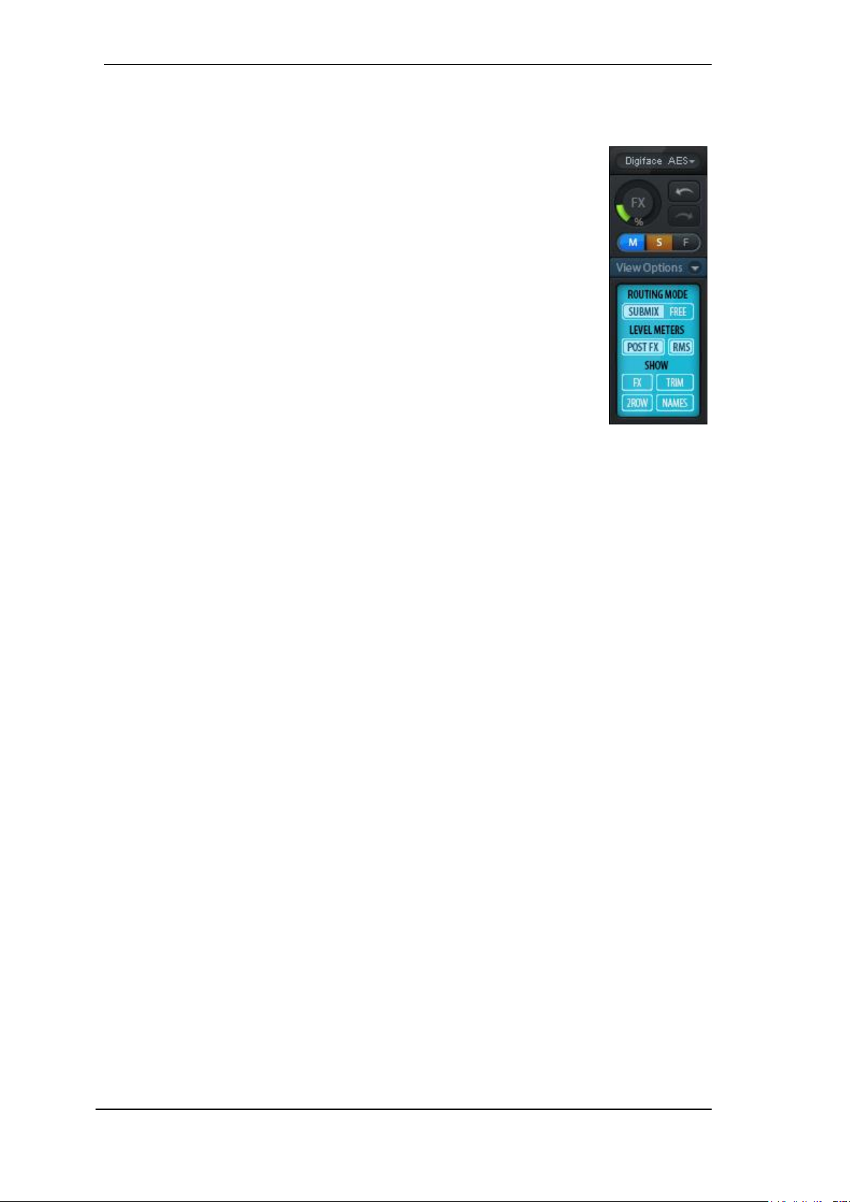
58
User's Guide Digiface AES © RME
24.5.1 View Options
The field Show combines different functions of routing, the level meters and the mixer view.
Routing Mode
Submix. The Submix view (default) is the preferred view and delivers the
quickest overview, operation and understanding of TotalMix. The click on
one of the Hardware Output channels selects the respective submix, all
other outputs are darkened. At the same time all routing fields are set to
this channel. With Submix view, it is very easy to generate a submix for any
output: select the output channel, adjust the fader and pans of first and second row – finished.
Free. The Free view is for advanced users. It is used to edit several sub-
mixes simultaneously, without the need to change between them. Here one
works with the routings fields of the input and playback channels only, which
then show different routing destinations.
Level Meters
Post FX. Switches all level meters before (pre) or after (post) EQ/Low Cut. Level changes by
these can be easily checked using this feature. Additionally the input signal can be checked
for overloads. It is recommended to use Post FX as default setting, as the extreme reduction
of a signal by LC/EQ is very seldom. Also all OVR displays of all level meters operate both
pre and post, efficiently preventing overloads going unnoticed.
RMS. The numerical level display in the channels displays peak or RMS.
Show
FX. Not available for the Digiface AES.
Trim. Activates all Trim buttons on all channels. TotalMix thus behaves like a conventional,
simple mixing desk. Each fader affects all active routings of the channel simultaneously, as if
the fader were a trim-pot in the hardware input.
2 Row. Switches the mixer view to 2 rows. Hardware Inputs and Software Playbacks are
placed side by side. This view saves a lot of space, especially in height.
Names. Display of the original names of channels when they had been renamed by the user.
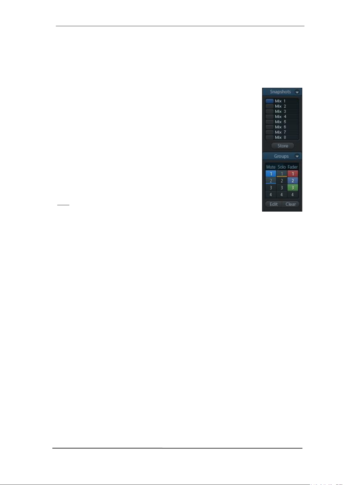
User's Guide Digiface AES © RME
59
24.5.2 Snapshots - Groups
Snapshots. Snapshots include all mixer settings, but no graphical elements like window posi-
tions, window size, number of windows, visible EQs or Settings, scroll states, Presets etc. Only
the state wide/narrow of the channels is registered. Moreover the Snapshot is only temporarily
stored. Loading a Workspace causes the loss of all stored Snapshots, when these all had not
been saved before in a Workspace, or separately via File / Save Snapshot as. Via File / Load
Snapshot the mixer states can be loaded individually.
Eight different mixes can be stored under individual names in the Snapshot
section. A click on any of the eight buttons loads the corresponding Snapshot.
A double click on the name field opens the dialog Input Name to edit the name.
As soon as the mixer state is changed the button starts flashing. A click on Store
lets all buttons flash, whereby the last loaded one, the base of the current state,
flashes inversely. The storage finishes by clicking the desired button (means
storage place). The storage process is exited by another click on the flashing
Store button.
The area Snapshots can be minimized by a click on the arrow in the title bar.
Groups. The area Groups provides 4 storage places each for fader, mute and
solo groups. The groups are valid per Workspace, being active and usable in
all 8 Snapshots. But with this they are also lost when loading a new workspace,
in case they have not been saved before in a different Workspace.
Note: The Undo function will help in case of an accidental overwrite or deletion
of the groups.
TotalMix uses flashing signals to guide you through the group setup. After a click on Edit and click
on the desired storage place all desired functions for this group have to be activated or selected.
The storage process is finished by another click on Edit.
When setting up a fader group make sure to not add faders that are at the top or low position,
unless all faders of that group have this position.
The Mute groups operate – other than the global mute – exclusively for the current routing. This
way you can not mute signals on all outputs unintentionally. Instead signals can be muted on
specific submixes by the push of a button.
A solo group operates exactly like the global solo, signals outside the current routing are not
affected.

60
User's Guide Digiface AES © RME
24.5.3 Channel Layout - Layout Presets
To maintain overview within TotalMix FX channels can be hidden. Channels can also be excluded
from being remoted. Under Options / Channel Layout a dialog lists all I/Os with their current state.
Selecting one or several channels enables the options to the right:
Hide Channel in Mixer/Matrix. The selected channels are no longer shown in TotalMix FX,
nor are they available via MIDI or OSC remote control.
Hide Channel in MIDI Remote 1-4. The selected channels are hidden for MIDI remote (CC
and Mackie Protocol).
Hide Channel in OSC Remote 1-4. The selected channels are hidden for OSC remote con-
trol.
Hidden channels in Mixer/Matrix are still fully functional. An existing routing/mixing/FX processing
stays active. But as the channel is no longer visible it cannot be edited anymore. At the same time
the hidden channels are removed from the list of remote controllable channels, to prevent them
from being edited unnoticed.
Hidden channels in MIDI Remote x are removed from the list of remote controllable channels.
Within an 8-channel block of a Mackie compatible control they are skipped. The control therefore
is no longer bound to consecutive orders. For example it will control channels 1, 2, and 6 to 11,
when channels 3 to 5 are hidden.
The same can be done for OSC. With unnecessary channels made invisible for the OSC remote
the more important channels are available as one block on the remote.
The dialog can be called directly from TotalMix by a right mouse click on any channel. The corresponding channel will then be preselected in the dialog.
Rows Inputs, Playbacks and Outputs are set up individually by the tabs at the top. In Use shows
which channels are currently used in the mixing process. In the above example the ADAT input
channel have been made invisible. When ADAT is not used this is an easy way to remove it from
the mixer completely.

User's Guide Digiface AES © RME
61
A double click onto any line opens the edit field for the Name (User) column. Editing channel
names in this dialog is quick, Enter jumps to the next line. The names of the channels in the
Control Room section can only be changed this way.
After clicking on a field in the Color column, the color of the channel name can be changed. The
locator picture below shows the effect and the available colors.
After finishing those settings the whole state can be stored as Layout Preset.
A click on Store and the desired memory slot makes the current channel layout
recallable anytime. The button All makes all channels temporarily visible again.
With a simple click on a button it will then be possible to easily switch views of
only the channels involved with the mixing of the drum section, the horn section,
the violins, or any other useful view. An optimized remote layout can be activated here as well, with or without visible changes. Double-click the default slot
name to enter any other name.
Layout Presets are stored within the Workspace, so make sure to save the current state before
loading a different Workspace!
The button Sub activates another useful special view. When in Submix view, Sub will cause all
channels to disappear that are not part of the currently selected Submix/Hardware Output. Sub
temporarily shows the mix based on all channels from Inputs and Playback row, independent from
the current Layout Preset. That makes it very easy to see and to verify which channels are
mixed/routed to the current output. Sub makes checking and verifying of mixes, but also the mix
editing itself, a lot easier, and maintains perfect overview even with lots of channels.
24.5.4 Scroll Location Markers
Another feature to improve overview and working with TotalMix FX are scroll location markers
(TotalMix view only). These are displayed automatically when the horizontal size of the TotalMix
FX window is smaller than the channel display requires. Shown on the right side of the scrollbar
of each row they have four elements:
Arrow to the left. A left
mouse click lets the
channels scroll to the
very first one, or most
left.
1. Marker number 1.
Scroll to the desired position and perform a
right mouse click on 1. A
dialog comes up with
precise information.
Once stored, a left
mouse click will scroll
the channels to the
stored position.
2. Marker number 2. See 1 for details.
Arrow to the right. A left mouse click lets the channels scroll to the last one, or most right.
Location markers are stored in the Workspace.
Application Examples
When the TotalMix FX window is intentionally made small in width, so only a few channels
are shown.
When some or all EQ or Dynamics panels are open. Then all relevant settings are always
visible, but require a lot of space horizontally.
!
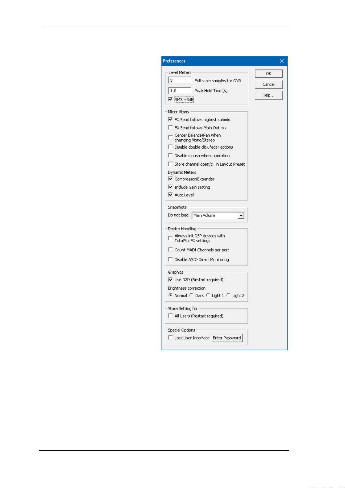
62
User's Guide Digiface AES © RME
24.6 Preferences
The dialog Preferences can be opened via the Options menu or directly via F2.
Level Meters
Full scale samples for OVR. Number of
consecutive samples to trigger an over
detection (1 to 10).
Peak Hold Time. Hold time of the peak
value. Adjustable from 0.1 up to 9.9 s.
RMS +3 dB. Shifts the RMS value by +3
dB, so that full scale level is identical for
Peak and RMS at 0 dBFS.
Mixer Views
FX Send follows highest Submix.
FX Send follows Main Out. Not availa-
ble for the Digiface AES - no FX.
Center Balance/Pan when changing
Mono/Stereo. When switching a stereo
channel into two mono channels the panpots are set fully left and right. This option
will set them to center instead.
Disable mouse wheel operation. Pre-
vents unintentional changes when using
the mouse wheel.
Disable double click fader action. Pre-
vents unintentional gain settings, for example when using sensitive touchpads.
Store channel open/close in Layout
Preset. Also loads the state of the chan-
nel panels (Settings/EQ Panel).
Dynamic Meters
Not available for the Digiface AES - no FX.
Snapshots
Do not load - Main Volume,
Main/Phones Volumes, Control Room
Settings. The selected values stored in
the Snapshot are not loaded, so the current setting is not changed.
Device Handling
Always init DSP devices with TotalMix
FX settings. Used to suppress the mis-
match message after using the unit stand-alone. Settings in the unit are lost.
Count MADI Channels per port. Not available with the Digiface AES.
Disable ASIO Direct Monitoring. Disables ASIO Direct Monitoring (ADM) for the Digiface
AES within TotalMix FX.
Graphics
Use D2D (Change requires restart). Default on. Can be deactivated to use a compatible but
CPU-taxing graphics mode, in case graphics problems show up.
Brightness Correction. Adjusts the brightness of the TotalMix FX graphics.

User's Guide Digiface AES © RME
63
Store Setting for
All Users (Restart required). See next chapter.
Special Options
Lock User Interface. Default off. Can be activated to freeze the current mix state. Faders,
buttons and knobs relating to the mix state can not be moved anymore.
Enter Password (Windows only). Secures the locked user interface with an additional pass-
word.
24.6.1 Store for Current or All Users
TotalMix FX stores all settings, workspaces and snapshots for the current user in:
XP: C:\Documents and Settings\ Username\Local Settings\ Application Data\TotalMixFX
Since Vista: C.\Users\Username\AppData\Local\TotalMixFX
Mac Current User: user/Library/Application Support/RME TotalMix FX
Mac All Users: /Library/Application Support/RME TotalMix FX
Current User ensures that when workstations are used by several people they all find their own
settings. In case the settings should be identical or given for any user, TotalMix FX can be
changed to use the All User directory. An admin could even write protect the file lastDigiface-
AES1.xml, which results in a complete reset to that file’s content whenever TotalMix FX is re-
started. The xml-file is updated on exit, so simply set up TotalMix as desired and exit it (right
mouse click on the symbol in the notification area or Exit), then change the file attribute.
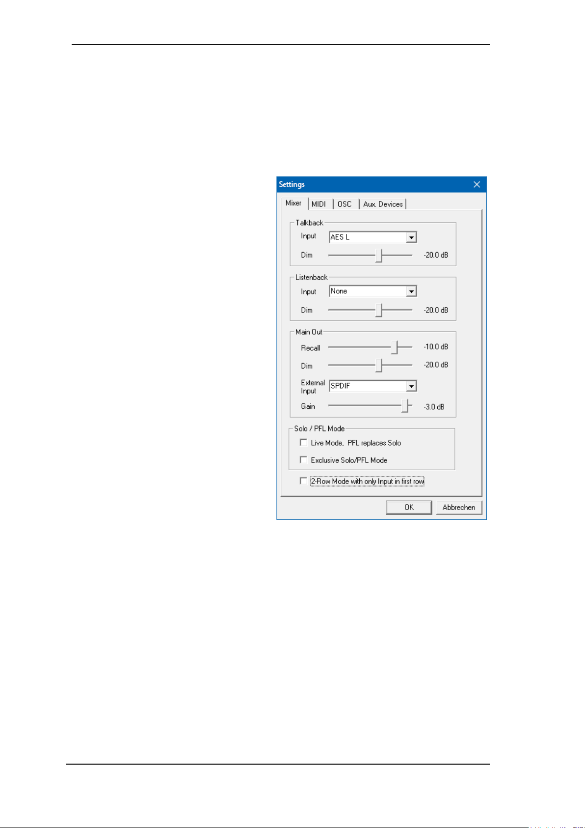
64
User's Guide Digiface AES © RME
24.7 Settings
The dialog Settings can be opened via the Options menu or directly via F3.
24.7.1 Mixer Page
On the mixer page some typical settings for the mixer operation are set, like Talkback source,
Dim amount when Talkback is active, the stored main volume or the input used for the External
Input function.
Talkback
Input. Selects the input channel of the
Talkback signal (microphone in control
room). Default: None.
Dim. Amount of attenuation of the signals
routed to the Phones in dB.
Listenback
Input. Selects the input channel of the Lis-
tenback signal (microphone in recording
room). Default: None.
Dim. Amount of attenuation of the signals
routed to the Main Out in dB.
Main Out
Recall. User defined listening volume, ac-
tivated by the Recall button at the unit or
in TotalMix.
Dim. Amount of attenuation for the Main
Out in dB.
External Input. Selects the stereo input
that replaces the mix signal on the Main
Out when activated. The volume of the
stereo signal is adjusted by the slider
Gain.
PFL Mode
Live Mode, PFL replaces Solo. PFL
means Pre Fader Listening. This feature
is very useful when operating TotalMix in a live environment, as it allows to quickly listen/monitor any of the inputs by hitting the Solo button. The monitoring happens on the output set for
the Cue signal via the Assign dialog.
Exclusive Solo/PFL Mode. Only a single Solo or PFL can be active at a time. Activating a
different one automatically deactivates the previous one.
2-Row Mode with only Input in first row. The Software Playback channels are shifted to
the lower row, beside the Hardware Outputs.

User's Guide Digiface AES © RME
65
24.7.2 MIDI Page
The MIDI page has four independent settings for up to four MIDI remote controls, using CC commands or the Mackie Control protocol.
Index
Select one of four settings pages and thus remote controls. Settings are remembered automatically. To activate or deactivate any of the four remote controls check or uncheck ‘In Use’.
MIDI Remote Control
MIDI In. Input where TotalMix receives MIDI Remote data.
MIDI Out. Output where TotalMix sends MIDI Remote data.
Disable MIDI in background. Deactivates MIDI Remote Control as soon as another appli-
cation is in the focus, or when TotalMix has been minimized.
Mackie Control Options
Enable Protocol Support. When disa-
bled TM FX will only react on the Control
Change commands of chapter 27.5.
Extender to. Sets the current remote to
be an extender to the main remote. Both
remotes will be shown as one block and
navigate simultaneously.
Map Stereo to 2 Mono Channels. One
fader controls one (mono) channel.
Should be disabled when stereo channels are used.
Submix Selection in Input/Playback
Row. Enables a selection of the submix
when in first row, without having to
change to the third row first. However,
when using both mono and stereo channels first and third row usually do not
match anymore, so the selection often
becomes unclear this way.
Enable full LCD support. Activates full
Mackie Control LCD support with eight
channel names and eight volume/pan
values.
Send User defined Names. Channel
names defined by the user will be sent
to the remote device via MIDI and – if
supported – shown in its display.
Send Level Messages. Activates the
transmission of the level meter data.
Peak Hold activates the peak hold function as set up for the TotalMix level meters in the preferences.
Note: When MIDI Out is set to NONE then TotalMix FX can still be controlled by Mackie Control
MIDI commands, but the 8-channel block is not marked as remote target.
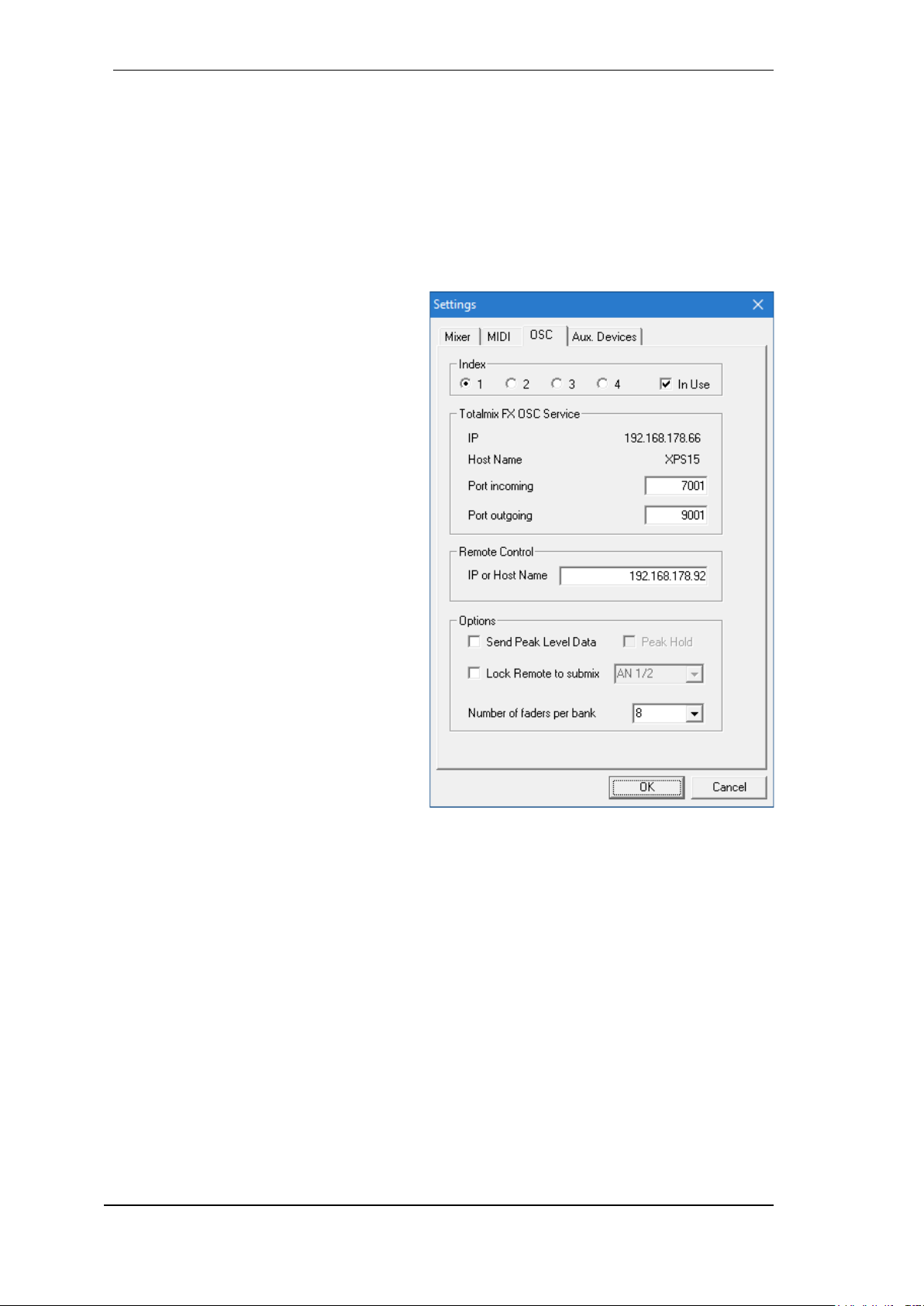
66
User's Guide Digiface AES © RME
24.7.3 OSC Page
The OSC page has four independent settings for up to four MIDI remote controls via Open Sound
Control (OSC). This is a network based remote protocol that can be used for example by Apple’s
iPad with the app TouchOSC or Lemur to wirelessly remote control TotalMix FX running on a Mac
or Windows computer.
Index
Select one of four settings pages and thus remote controls. Settings are remembered automatically. To activate or deactivate any of the four remote controls check or uncheck ‘In Use’.
TotalMix FX OSC Service
IP. Shows the network address of the
computer running TotalMix FX (local
host). This address must be entered on
the remote side.
Host Name. Local computer name.
Port incoming. Must match the remote
entry ‘Port outgoing’. Typical values are
7001 or 8000.
Port outgoing. Must match the remote
entry ‘Port incoming’. Typical values are
9001 or 9000.
Remote Control
IP or Host name. Enter the IP or host
name of the remote control. Please note
that the IP number usually works better
than the host name.
Options
Send Peak Level Data. Activates the
transmission of the peak level meter
data. Peak Hold activates the peak hold
function as set up for the TotalMix level
meters in the preferences.
Lock Remote to submix. When acti-
vated the current remote control can only
modify the submix selected from the
drop-down list. This prevents havoc in
multi-remote monitoring environments.
Number of faders per bank. Available choices are 8 (default), 12, 16, 24, 32 and 48. Note
that when working in underperforming networks, especially wireless, a higher number of faders might not work as smooth as expected.

User's Guide Digiface AES © RME
67
24.7.4 Aux Devices
The RME OctaMic XTC is a highly flexible hiquality 8-channel microphone, line and instrument preamp with integrated ADconversion to ADAT, AES/EBU and MADI,
plus 4 channels of DA-conversion for monitoring. It can be used as universal front-end
for the Digiface AES and other interfaces.
To simplify operation the most important parameters of the XTC (gain, 48V, phase,
mute, AutoSet) can be controlled directly
from the TotalMix FX input channels. This
special remote control uses MIDI of any format (DIN, USB, MIDI over MADI).
Device Settings
Digital Channels. Select where the Oc-
taMic XTC sends its 8 analog channels
to (Digiface AES: ADAT channels 1-8)
Device. At this time only the OctaMic
XTC is supported and can be chosen.
MIDI Settings
MIDI In. Set the currently used MIDI connection to the OctaMic XTC.
MIDI Out. Set the currently used MIDI connection to the OctaMic XTC.
Device ID. Default 0. This setting relates to the current choice in Digital Channels.
When using more than one OctaMic XTC these must have different Device IDs (configuration is
done at the OctaMic XTC). Aux Devices supports to set different Device IDs to the 8-channel
blocks as well. Storing the setting is done automatically when selecting a Device ID. To check the
current assignments toggle the two 8-channel blocks.
The screenshot to the right shows what happens as
soon as the above settings have been confirmed with
OK. The MADI channels show new elements for
phantom power, Inst/PAD, Gain and AutoSet. Control
operates bidirectional, so changing the gain at the unit
will be mirrored in the TotalMix channels. Changing
the gain in TotalMix FX will set the gain in the unit,
which is also shown on the unit’s display.
For the remote to work the XTC’s currently used MIDI
I/Os have to be set to Control. More details are found
in the manual of the OctaMic XTC.

68
User's Guide Digiface AES © RME
24.8 Hotkeys and Usage
TotalMix FX has many hotkeys and mouse/hotkey combinations to speed up and simplify the
usage. The below description refers to Windows. On Mac substitute Ctrl in the below list with the
command key ( ).
The Shift key enables a fine-tuning of the gain with all faders and in the Matrix. On all knobs it
will speed up the setting.
A click on a fader with held down Shift key adds the fader to the temporary fader group.
A click in the fader path with held down Ctrl key will let the fader jump to 0 dB, at the next click
to −∞. Same function: Double click of the mouse.
Clicking on one of the Panorama or Gain knobs with held down Ctrl key lets the knob jump to
center position. Same function: Double click of the mouse.
Clicking on the Panorama knob with held down Shift key lets the knob jump to fully left, with
Shift-Ctrl to fully right.
Clicking on one of the channel settings buttons (slim/normal, Settings, EQ, Dynamics) with held
down Ctrl key lets all channels to the right change their state. For example all panels can be
opened/closed simultaneously.
A double click of the mouse on a knob or its numerical field opens the according Input Value
dialog. The desired value can then be set by keyboard.
Dragging the mouse from a parameter field increases (move up) or decreases (move down) the
value in the field.
Ctrl-N opens the dialog Function Select to open a new TotalMix window.
Ctrl-W opens the dialog File Open of the operating system to load a TotalMix Workspace file.
The key W starts the dialog Workspace Quick Select for a direct selection or storage of up to 30
Workspaces.
The key M switches the active window to Mixer view. The key X switches the active window to
Matrix view. Ctrl-M opens a new Mixer window, Ctrl-X opens a new Matrix window. Another CtrlM or Ctrl-X closes the new window again.
F1 opens the online help. The Level Meter setup dialog can be opened with F2 (same as in
DIGICheck). The dialog Preferences is opened with F3.
Alt-F4 closes the current window.
Alt and number keys 1 to 8 (not on the numeric keypad!) will load the corresponding Workspace
from the Workspace Quick Select feature (hotkey W).

User's Guide Digiface AES © RME
69
24.9 Menu Options
Deactivate Screensaver: When active (checked) any activated Windows screensaver will be
disabled temporarily.
Always on Top: When active (checked) the TotalMix window will always be on top of the Win-
dows desktop. Note: This function may result in problems with windows containing help text, as
the TotalMix window will even be on top of those windows, so the help text isn't readable.
Enable MIDI /OSC Control: Activates external MIDI control of the TotalMix mixer. In Mackie
Protocol mode the channels which are currently under MIDI control are indicated by a colour
change of the name field.
Submix linked to MIDI / OSC controller (1-4). The 8-channel group follows the currently selected submix, means Hardware Output, when a different submix is chosen on the remote as well
as when doing this in TotalMix. When using multiple windows it can be useful to deactivate this
feature for specific windows. The view will not change then.
Preferences: Opens a dialog box to configure several functions of the level meters and the mixer.
See chapter 24.6.
Settings. Opens a dialog box to configure several functions like Talkback, Listenback, Main Out
and the MIDI Remote Control. See chapter 24.7.
Channel Layout. Hide channels visually and from remote. See chapter 24.5.3.
ARC & Key Commands. Opens a window to configure the programmable buttons of the Stand-
ard, Advanced and Advanced Remote USB, and of the computer’s keyboard keys F4 to F8.
Reset Mix. Offers several options to reset the mixer state:
Straight playback with all to Main Out. All Playback channels are routed 1:1 to the Hard-
ware Outputs. Simultaneously all playbacks are mixed down to the Main Out. The faders in
the third row are not changed.
Straight Playback. All Playback channels are routed 1:1 to the Hardware outputs. The faders
in the third row are not changed.
Clear all submixes. Deletes all submixes.
Clear channel effects. Switches off all EQs, Low Cuts and Stereo Width and sets their knobs
to default position.
Set output volumes. All faders of the third row set to 0 dB, Main and Speaker B to -10 dB.
Reset channel names. Removes all names assigned by the user.
Set all channels mono. Reconfigures all TotalMix FX channels to mono mode.
Set all channels stereo. Reconfigures all TotalMix FX channels to stereo mode.
Set inputs mono / outputs stereo (ADM). Preferred setup for best ASIO Direct Monitoring
compatibility. In most cases mono hardware outputs will break ADM. Mono inputs are in most
cases compatible. If not wrong panning might occur.
Total Reset. Playback routing 1:1 with mixdown to Main Out. Switches off all other functions.

70
User's Guide Digiface AES © RME
Operational Mode. Defines TotalMix FX basic operational mode. Choices are Full Mode (default,
mixer active, all routing options available), and Digital Audio Workstation Mode (straight playback
routing, no input mix). See chapter 28 for details.
Offline Device Setup. Makes all devices supported by TotalMix FX available offline. This 'demo'
mode can load and save workspaces, and thus also allows offline editing and visual inspection of
workspaces and snapshots.
Setup: Select the desired devices and add them to the list of Configured Devices by clicking Add.
Close the dialog by clicking OK.
Mixer and Matrix can now be opened even without a connected device. The device selection is
done on the top right via the device selection field in the Control Strip.
Network Remote Settings. Settings to remote control TotalMix FX by TotalMix Remote via network. See chapter 29.
Store Current state into device. The unit can store up to 6 setups (the current state) in its own
memory. This function has been developed especially for the stand-alone mode operation, where
there are no playback channels. Therefore using it under Windows, Mac or iOS will result in incomplete setups.
24.10 Menu Window
Zoom Options 100%, 135%, 200%, 270%. Depending on the size of the monitor and the current
resolution TotalMix FX might be much too small and the controls too tiny to easily operate them.
Together with the 2 Row mode these options give a lot of different window sizes that suit all
monitors and resolutions currently existing.
Hide Control Strip. Shifts the Control Strip out of the visible area to gain more space for other
elements.

User's Guide Digiface AES © RME
71
25. The Matrix
25.1 Overview
The mixer window of TotalMix looks and operates similar to mixing desks, as it is based on a
conventional stereo design. The matrix display presents a different method of assigning and routing channels, based on a single channel or monaural design. The matrix view of the Digiface AES
has the look and works like a conventional patchbay, adding functionality way beyond comparable
hardware and software solutions. While most patchbays will allow you to connect inputs to outputs
with just the original level (1:1, or 0 dB, as known from mechanical patchbays), TotalMix allows
you to use a freely definable gain value per crosspoint.
Matrix and TotalMix are different ways of displaying the same processes. Because of this both
views are always fully synchronized. Each change in one view is immediately reflected in the
other view as well.
25.2 Elements of the Matrix View
The visual design of the Matrix is determined by the architecture of the Digiface AES system:
Horizontal labels. All hardware outputs
Vertical labels. All hardware inputs. Below are all playback channels.
Green 0.0 dB field. Standard 1:1 routing
Dark grey field with number. Shows the current
gain value as dB
Blue field. This routing is muted
Red field. Phase 180° (inverted)
Dark grey field. No routing.
To maintain overview when the window size has been reduced, the labels are floating. They won't
leave the visible area when scrolling. A right mouse click on the labels brings up the context menu
with the exact same options as in the mixer view: Copy / Mirror / Paste /Clear input channels and
submixes.
25.3 Operation
Using the Matrix is a breeze. It is very easy to indentify the current crosspoint, because the outer
labels light up in orange according to the mouse position.
If input 1 is to be routed to output 1, use the mouse and click one time on crosspoint In 1 / AN
1 with held down Ctrl key. Two green 0.0 dB field pop in, another click removes them.
To change the gain (equals the use of a different fader position, see simultaneous display of
the mixer view), drag the mouse up or down, starting from the gain field. The value within the
field changes accordingly. The corresponding fader in the mixer view is moving simultaneously, in case the currently modified routing is visible.
On the right side is the Control Strip from the mixer window, adapted to the Matrix. The button
for the temporary fader group is missing as well as all View options, as they don’t make sense
here. Instead the button Mono Mode lets you decide whether all the actions performed in the
Matrix are valid for two channels or just one.

72
User's Guide Digiface AES © RME
The Matrix not always replaces the mixer view, but it significantly enhances the routing capabilities
and - more important - is a brilliant way to get a fast overview of all active routings. It shows you
in a glance what's going on. And since the Matrix operates monaural, it is very easy to set up
specific routings with specific gains.
26. Tips and Tricks
26.1 ASIO Direct Monitoring (Windows)
Programs that support ADM (ASIO Direct Monitoring - Samplitude, Sequoia, Cubase, Nuendo
etc.) send control commands to TotalMix. This is directly shown by TotalMix. When a fader is
moved in the ASIO host the corresponding fader in TotalMix will move too. TotalMix reflects all
ADM gain and pan changes in real-time.
But: the faders only move when the currently activated routing (the selected submix) corresponds
to the routing in the ASIO host. The Matrix on the other hand will show any change, as it shows
all possible routings in one view.
26.2 Copy a Submix
TotalMix allows you to copy complete submixes to other outputs. In case a complex submix is
need with only a few changes on a different output, the whole submix can be copied to that output.
Right click with the mouse on the original submix output, means Hardware Output. In the context
menu select Copy Submix. Then right click on the new submix output, choose Paste Submix in
the context menu. Now fine tune the submix.
26.3 Doubling the Output Signal (Mirror)
If a mix should be sent out via two (or more) different hardware outputs simply mirror that mix to
any number of other outputs. A right click on the original output brings up the option to Copy/Mirror
<name>. Another right click on the new output, then selecting Mirror of Output <name> will paste
the whole submix and then synchronize it automatically to any future changes. The outputs now
always send out the same signals, but their main volume (fader) and the EQ and Dynamics settings stay fully independent.
26.4 Delete a Submix
The easiest and quickest way to delete complex routings is by selection of the according output
channel in the mixer view by a right mouse click, and selection of the menu entry Clear Submix.
As TotalMix FX includes an unlimited undo the delete process can be undone without any problem.
26.5 Copy and Paste everywhere
The above three tips use functions found in the right click context menu available on all channels
of the mixer view. These menus are also available in the Matrix, but only directly on the channel
labels. They are self-explanatory and automatically adjust to where the click is performed. The
input channels offer Clear, Copy input, Paste the input mix and Paste its FX. On a playback
channel Copy, Paste and Clear the playback mix are available. On an output channel Copy and
Mirror functionality for the current submix and copying of the FX settings is offered.
These options are very advanced and mighty tools to quickly do the impossible. Still there is no
need to fear breaking something, as a simple click (or several) on the Undo button will get you
back to where you started!

User's Guide Digiface AES © RME
73
26.6 Recording a Submix - Loopback
TotalMix includes an internal loopback function, from the Hardware Outputs to the recording software. Instead of the signal at the hardware input, the signal at the hardware output is sent to the
record software. This way, submixes can be recorded without an external loopback cable. Also
the playback from a software can be recorded by another software.
The function is activated by the Loopback button in the Settings panel of the Hardware Outputs.
In loopback mode, the signal at the hardware input of the corresponding channel is no longer sent
to the recording software, but still passed through to TotalMix. Therefore TotalMix can be used to
route this input signal to any hardware output. Using the subgroup recording, the input can still
be recorded on a different channel.
As each of the 14 stereo hardware outputs can be routed to the record software, and none of
these hardware inputs get lost, TotalMix offers an overall flexibility and performance not rivalled
by any other solution.
The risk of feedbacks, a basic problem of loopback methods, is low, because the feedback can
not happen within the mixer, only when the audio software is switched into monitoring mode.
The block diagram shows how the software's input signal is played back, and fed back from the
Hardware Output to the software input.
The block diagram also shows why with activated Loopback the EQ of the Hardware Output is
now within the record path. With Loopback active the EQ of the input is not in the record path,
only in the monitoring path, even when the Option DSP – Record EQ is activated.
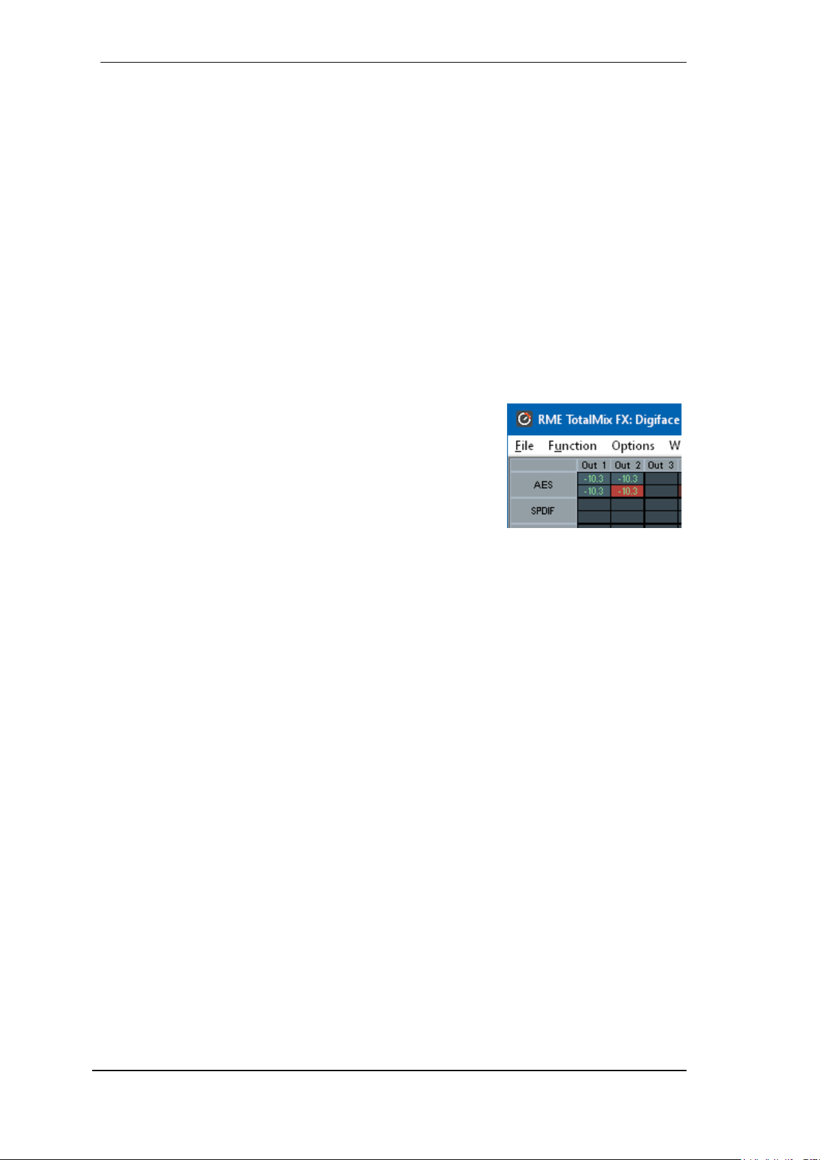
74
User's Guide Digiface AES © RME
Recording a Software's playback
In real world application, recording a software's output with another software will show the following problem: The record software tries to open the same playback channel as the playback software (already active), or the playback one has already opened the input channel which should be
used by the record software.
This problem can easily be solved. First make sure that all rules for proper multi-client operation
are met (not using the same record/playback channels in both programs). Then route the playback
signal via TotalMix to a hardware output in the range of the record software, and activate Loopback for recording.
Mixing several input signals into one record channel
In some cases it is useful to record several sources into only one track. For example when using
two microphones recording instruments and loudspeakers, TotalMix' Loopback mode saves an
external mixing desk. Simply route/mix the input signals to the same output (third row), then redefine this output into a record channel via Loopback. This way any number of input channels
from different sources can be recorded into one single track.
26.7 MS Processing
The mid/side principle is a special positioning technique for microphones, which results in a mid signal on one channel and a side
signal on the other channel. This information can be transformed
back into a stereo signal quite easily. The process sends the monaural mid channel to left and right, the side channel too, but phase
inverted (180°) to the right channel. For a better understanding:
the mid channel represents the function L+R, while the side channel represents L-R.
During record the monitoring needs to be done in 'conventional' stereo. Therefore TotalMix also
offers the functionality of a M/S-decoder. Activation is done in the Settings panel of the Hardware
Input and Software Playback channels via the MS Proc button.
The M/S-Processing automatically operates as M/S encoder or decoder, depending on the source
signal format. When processing a usual stereo signal, all monaural information will be shifted into
the left channel, all stereo information into the right channel. Thus the stereo signal is M/S encoded. This yields some interesting insights into the mono/stereo contents of modern music productions. Additionally some very interesting methods of manipulating the stereo base and generating stereo effects come up, as it is then very easy to process the side channel with Low Cut,
Expander, Compressor or Delay.
The most basic application is the manipulation of the stereo width: a change of the level of the
side channel allows to manipulate the stereo width from mono to stereo up to extended.

User's Guide Digiface AES © RME
75
27. MIDI Remote Control
27.1 Overview
TotalMix can be remote controlled via MIDI. It is compatible to the widely spread Mackie Control
protocol, so TotalMix can be controlled with all hardware controllers supporting this standard.
Examples are the Mackie Control, Tascam US-2400 or Behringer BCF 2000.
Additionally, the stereo output faders (lowest row) which are set up as Main Out in the Control
Room section can also be controlled by the standard Control Change Volume via MIDI channel
1. With this, the main volume of the Digiface is controllable from nearly any MIDI equipped hardware device.
MIDI Remote Control always operates in View Submix mode, even when the View Option Free is
currently selected in TotalMix FX.
27.2 Mapping
TotalMix supports the following Mackie Control surface elements*:
Element: Meaning in TotalMix:
Channel faders 1 – 8 volume
Master fader Main Out channel fader
V-Pots 1 – 8 pan
pressing V-Pot knobs pan = center
CHANNEL LEFT or REWIND move one channel left
CHANNEL RIGHT or FAST FORWARD move one channel right
BANK LEFT or ARROW LEFT move eight channels left
BANK RIGHT or ARROW RIGHT move eight channels right
ARROW UP or Assignable1/PAGE+ move one row up
ARROW DOWN or Assignable2/PAGE- move one row down
EQ Master Mute
PLUGINS/INSERT Master Solo
STOP Dim Main Out
PLAY Talkback
PAN Mono Main Out
FLIP Speaker B
DYN/INSTRUMENT TrimGains
MUTE Ch. 1 – 8 Mute
SOLO Ch. 1 – 8 Solo
SELECT Ch. 1 – 8 Select
REC Ch. 1 – 8 select output bus (Submix)
RECORD Recall
F1 - F8 load Snapshot 1 - 8
F9 select Main Out
F10 - F12 select Cue Phones 1 - 3
*Tested with Behringer BCF2000 Firmware v1.07 in Mackie Control emulation for Steinberg mode and with Mackie Control
under Mac OS X.

76
User's Guide Digiface AES © RME
27.3 Setup
Open the Preferences dialog (menu Options or F3). Select the MIDI Input and MIDI Output port
where your controller is connected to.
When no feedback is needed select NONE as MIDI Output.
Check Enable MIDI Control in the Options menu.
27.4 Operation
The channels being under Mackie MIDI control are indicated by a colour change of the name
field, black turns to brown.
The 8-fader block can be moved horizontally and vertically, in steps of one or eight channels.
Faders can be selected to gang them.
In Submix View mode, the current routing destination (output bus) can be selected via REC Ch.
1 – 8. This equals the selection of a different output channel in the lowest row by a mouse click
when in Submix View. In MIDI operation it is not necessary to jump to the lowest row to perform
this selection. This way even the routing can be easily changed via MIDI.
Full LC Display Support: This option in Preferences (F3) activates complete Mackie Control LCD
support with eight channel names and eight volume/pan values. When Full LC Display Support is
turned off, only a brief information about the first fader of the block (channel and row) is sent. This
brief information is also available on the LED display of the Behringer BCF2000.
Disable MIDI in Background (menu Options, Settings) disables the MIDI control as soon as another application is in the focus, or in case TotalMix has been minimized. This way the hardware
controller will control the main DAW application only, except when TotalMix is in the foreground.
Often the DAW application can be set to become inactive in background too, so that MIDI control
is switched between TotalMix and the application automatically when switching between both
applications.
TotalMix also supports the 9th fader of the Mackie Control. This fader (labelled Master) will control
the stereo output faders (lowest row) which are set up as Main Out in the Control Room section.
Extender support (Settings, tab MIDI) enables the use of the special Extender mixing desk, but
also the addition of any other Mackie compatible remote. Setting the main remote as number 2
and the extender as number 1 will cause the extender to be on the left side. Using this function
the remotes will be shown as one fader block and navigate as one.

User's Guide Digiface AES © RME
77
27.5 MIDI Control
The hardware output which is set up as Main Out can be controlled by the standard Control
Change Volume via MIDI channel 1. With this, the main volume of the Digiface is controllable
from nearly any MIDI equipped hardware device.
Even if you don't want to control all faders and pans, some buttons are highly desired to be avail-
able in 'hardware'. These are mainly the Talkback and the Dim button, and the monitoring options
(listen to Phones submixes). Fortunately a Mackie Control compatible controller is not required to
control these buttons, as they are steered by simple Note On/Off commands on MIDI channel 1.
The notes are (hex / decimal / keys):
Dim: 5D / 93 / A 6
Mono: 2A / 42 / #F 2
Talkback: 5E / 94 / #A 6
Recall: 5F / 95 / B 6
Speaker B: 32 / 50 / D3
Cue Main Out: 3E / 62 / D 4
Cue Phones 1: 3F / 63 / #D 4
Cue Phones 2: 40 / 64 / E 4
Cue Phones 3: 41 / 65 / F 4
Cue Phones 4: 42 / 66 / #F 4
Snapshot 1: 36 / 54 / #F 3
Snapshot 2: 37 / 55 / G 3
Snapshot 3: 38 / 56 / #G 3
Snapshot 4: 39 / 57 / A 3
Snapshot 5: 3A / 58 / #A 3
Snapshot 6: 3B / 59 / B 3
Snapshot 7: 3C / 60 / C 4
Snapshot 8: 3D / 61 / #C 4
Trim Gains: 2D / 45 / A 2
Master Mute: 2C / 44 / #G 2
Master Solo: 2B / 43 / G 2
Note: The hex value is standardized, the key is not. If it doesn’t work try all notes one octave
lower.
Furthermore all faders of all three rows can be controlled via simple Control Change commands.
The format for the Control Change commands is:
Bx yy zz
x = MIDI channel
yy = control number
zz = value
The first row in TotalMix is addressed by MIDI channels 1 up to 4, the middle row by channels 5
up to 8 and the bottom row by channels 9 up to 12.
16 Controller numbers are used: 102 up to 117 (= hex 66 to 75). With these 16 Controllers (=
faders) and 4 MIDI channels each per row, up to 64 faders can be controlled per row (as required
by the HDSPe MADI).

78
User's Guide Digiface AES © RME
Examples for sending MIDI strings:
- Set input 1 to 0 dB: B0 66 68
- Set input 17 to maximum attenuation: B1 66 0
- Set playback 1 to maximum: B4 66 7F
- Set Output 16 to 0 dB: B8 75 68
Note: Sending MIDI strings requires to use programmer's logic for the MIDI channel, starting with
0 for channel 1 and ending with 15 for channel 16.
Further functions:
- Trim Gains On: BC 66 xx (BC = MIDI channel 13, xx = any value)
- Trim Gains Off: BC 67 xx or select a submix
Select submix (fader) in third row:
- channel 1/2: BC 68/69 xx
- channel 3/4: BC 6A/6B xx
etc.
Input Gain control is available via CC9, value range as the gain itself (up to 65). The MIDI channel determines the controlled channel, from 1 to 16 (Digiface AES: 5/6). For this to work, Enable
MIDI Control in the Options menu has to be activated.
27.6 Stand-Alone MIDI Control
When not connected to a computer, the Digiface AES can be controlled directly via MIDI. The
stand-alone MIDI control mode is activated in the unit’s menu Options, Hardware/Diagnosis,
Standalone MIDI.
Note: When not needed the stand-alone MIDI operation should not be active, as the unit will react
on MIDI notes after power-on, and will also send MIDI notes.
Control is performed via both the Mackie Control protocol and some standard MIDI functions
(see below). In stand-alone mode not all functions known from TotalMix are available, because
some of them aren't hardware, but software routines. Functions like Talkback, Mono, Solo, rela-
tive ganging of the faders, Monitor Main and Monitor Phones are realized by complex software
code, therefore not available in stand-alone MIDI control operation.
Still many functions, and especially the most important functions to control the Digiface AES, are
implemented in hardware, thus available also in stand-alone mode:
All faders and pans of the first and third row
Mute of the input signal per channel
Ganging via 'Select'
Choice of the routing destination, i.e. the current submix
Sending of LED and display data to the MIDI controller
The second row (software playback) is skipped. The Digiface AES sends display data as brief
information, enabling an easy navigation through lines and rows. Other data like PAN and miscellaneous status LEDs are supported as well.

User's Guide Digiface AES © RME
79
In stand-alone mode the unit always operates in View Submix mode. Only this way the routing
destination can be changed, and several mixdowns/submixes can be set up quickly and easily. If
the current TotalMix setup is transferred into the Digiface via 'Flash current mixer state', the currently selected submix output is also pre-configured in the hardware for stand-alone MIDI remote
operation.
Mackie Control Protocol
The stand-alone operation supports the following Mackie Control surface elements*:
*Tested with Behringer BCF2000 Firmware v1.07 in Mackie Control emulation for Steinberg mode.
Element: Meaning in Digiface:
Channel faders 1 – 8 volume
V-Pots 1 – 8 pan
pressing V-Pot knobs pan = center
CHANNEL LEFT or REWIND move one channel left
CHANNEL RIGHT or FAST FORWARD move one channel right
BANK LEFT or ARROW LEFT move eight channels left
BANK RIGHT or ARROW RIGHT move eight channels right
ARROW UP or Assignable1/PAGE+ move one row up
ARROW DOWN or Assignable2/PAGE- move one row down
STOP Dim Main Out
EQ Master Mute
MUTE Ch. 1 – 8 Mute
SELECT Ch. 1 – 8 Select
REC Ch. 1 – 8 select output bus (current submix)
F1 – F6 load Setup 1 - 6
Additionally the following functions are available via simple MIDI notes on MIDI channel 1:
Dim: 5D / 93 / A 6
Setup 1: 36 / 54 / #F 3
Setup 2: 37 / 55 / G 3
Setup 3: 38 / 56 / #G 3
Setup 4: 39 / 57 / A 3
Setup 5: 3A / 58 / #A 3
Setup 6: 3B / 59 / B 3
Loading the Setups stored in the device enables a quick configuration change of the UFX. With
this any possible operation state can be activated by the push of a button at any time.

80
User's Guide Digiface AES © RME
27.7 Loopback Detection
The Mackie Control protocol requires feedback of the received commands, back to the hardware
controller. So usually TotalMix will be set up with both a MIDI input and MIDI output. Unfortunately
any small error in wiring and setup will cause a MIDI feedback loop here, which then completely
blocks the computer (the CPU).
To prevent the computer from freezing, TotalMix sends a special MIDI note every 0.5 seconds to
its MIDI output. As soon as it detects this special note at the input, the MIDI functionality is disabled. After fixing the loopback, check Enable MIDI Control under Options to reactivate the TotalMix MIDI.
27.8 OSC (Open Sound Control)
Besides simple MIDI notes, the Mackie Protocol and Control Change commands, TotalMix FX
can also be controlled by the Open Sound Control, OSC. For details on setup and usage see
chapter 24.7.3.
An OSC implementation chart can be downloaded from the RME website:
http://www.rme-audio.de/downloads/osc_table_totalmix_new.zip
RME offers a free iPad template for the iOS app TouchOSC (by Hexler, available in the Apple
App-Store):
http://www.rme-audio.de/downloads/tosc_tm_ipad_template.zip
The RME forum hosts further information, more templates (iPhone…) and lots of useful user feed-
back.
28. DAW Mode
Users that work exclusively with their DAW software, and don’t want to use TotalMix FX for addi-
tional routing tasks, need a way to be sure that TotalMix FX currently doesn’t change the DAW’s
routing. While Reset Mix can do so, those users would be better served with a very simple surface
that offers the interface’s hardware controls (gain, phantom control, instrument…), but guarantees
a straight 1:1 routing for all playback channels, and has no hardware monitoring of the input
channels (which is then done by the DAW software).
For such cases TotalMix FX includes an alternative operating mode. It can be booted into the so
called DAW mode. This simplified interface is for anyone performing all monitoring and routing
within the DAW. The DAW mode restarts TM FX into a light version with just two rows, no playback
row, and no mixing faders in the input row. Routing is 1:1 only. Just the hardware controls (if
existing) and hardware output levels are available.
To change the current mode go to the menu, Options, and click on Operational Mode. Choices
are Full Mode (default, mixer active, all routing options available), and Digital Audio Workstation
Mode (straight playback routing, no input mix).
Several useful, advanced features are still available in TotalMix FX in DAW mode:
Talkback, External Input
Phones definition and handling with Talkback
Speaker A / B
All FX (EQ)
Mute and Solo
Cue / PFL
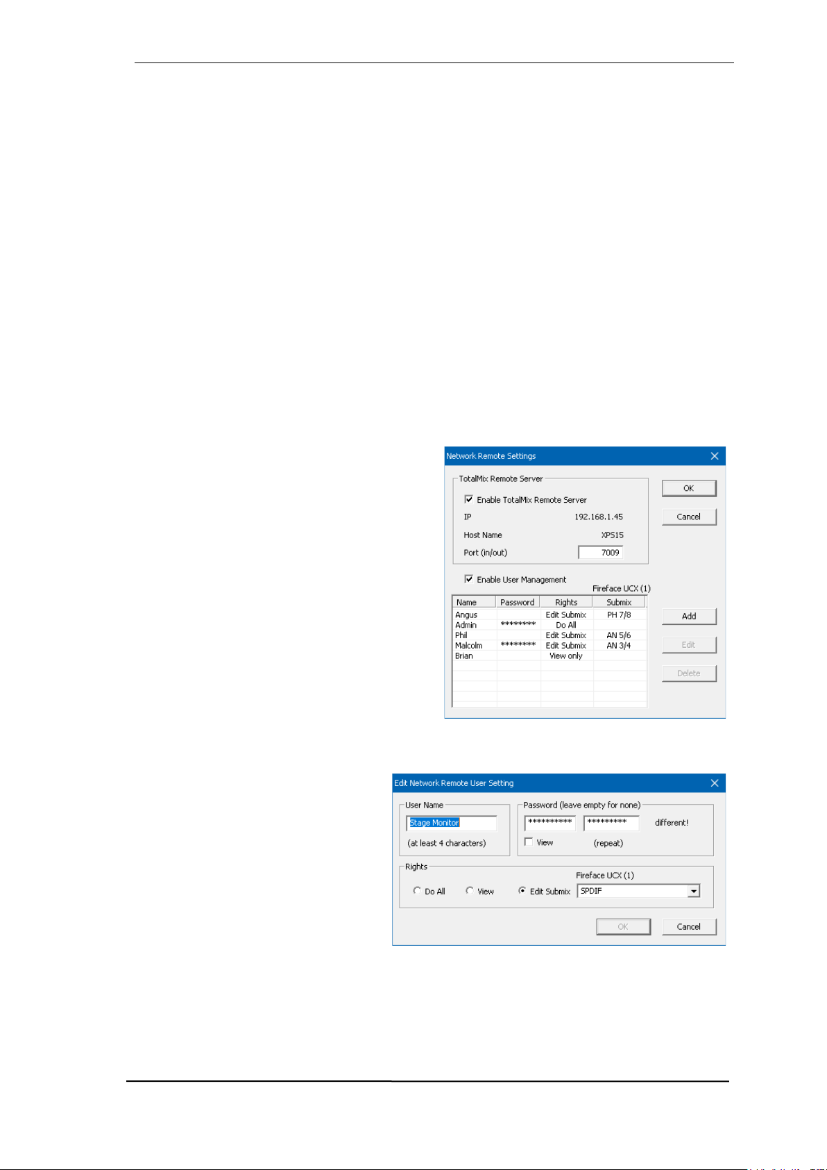
User's Guide Digiface AES © RME
81
29. TotalMix Remote
TotalMix Remote is a remote control for TotalMix FX v1.50 and up, to control the hardware mixer
and effects in RME audio interfaces. TotalMix Remote mirrors the current state of the host system
on the iPad and Windows/Mac computers - the entire mixing state, the complete routing, all FX
settings, up to the level meters, and everything in real-time. TotalMix Remote supports up to three
hosts with multiple interfaces each, allowing Apple's popular iPad and Windows/Mac computers
to adjust all the mixer and FX settings from a distance, via Ethernet and WiFi.
Supported Hardware
TotalMix Remote communicates with TotalMix FX 1.50 or up. Any RME hardware that can be
used with TotalMix FX is supported automatically.
Quick Start
On the host (the computer with the connected audio interface) go to the TotalMix FX menu Options, Network Remote Settings. Click Enable TotalMix Remote Server to start this service. Under
Windows a Firewall warning will come up. Allow TotalMix FX or it won't work. This dialog also
shows the host's IP, like 192.168.1.45.
Make sure both host and remote computer / iPad
reside in the same network. Start TotalMix Remote on the remote computer / iPad (not on the
host!). On the iPad, tap on the gear symbol in the
upper right corner, then on Host Connection Set-
tings. On Windows / Mac either the dialog comes
up automatically or can be called from the
Search Connected Hosts dialog. Type in the
host's IP address (like 192.168.1.45) into the IP
field of Host Connection 1, and make sure it is
activated. The port defaults to 7009 and usually
must not be changed. In case this port is unexpectedly occupied a warning message will be issued. Choose a different port then. Under Windows a Firewall warning will come up. Allow TotalMix Remote or it won't work.
Tap Done on top or click Ok. In the mixer view the state should change from offline to connected
within a few seconds.
The Add button provides access to the
user-management that can be configured in detail. Here users can be defined, with and without a password, and
the rights can be assigned to viewing
only, changing a specific sub-mix, or full
access. For example, using Total-Mix
FX as a monitor controller for all band
members, user-management prevents
the bassist from changing the guitarist's
monitor mix. Or the drummer making
himself too loud. Etc.

82
User's Guide Digiface AES © RME
Tip
The remotes have the option Sync Channel Layouts active as default (in Preferences). This option
transfers the Layout Presets and the current Channel Layout state from host to remote. Apart
from the channel width state this option makes a mirror-style setup most easy. But when using
the remote as individual setup, make sure to disable this option to have independent Layout Presets on the remote.
Limitations
• Mixer View & GUI. When connected the remote computer / iPad will immediately have the complete routing and FX settings of the host, including mono and stereo channels, but not the host's
GUI setup, like panel states open/closed of Settings/EQ/Dynamic, FX panel visibility, 2-Row or 3Row mode and channel width. Channel width states can be stored as usual per Snapshot and
completely as Workspace, locally on the remote computer. They need to be loaded manually after
loading a Workspace on the host in case a 100% identical view is required.
• Workspaces. The Remote shows the Quick Workspaces (hotkey W on Windows/Mac) stored
on the host, and allows to remotely load them. It is not possible to save complete Workspaces
with mixer state from the Remote, or on the Remote. The Workspaces saved locally include GUI
information only (Channel state wide/narrow, Channel Layouts, window size and position) and
further local settings, to be able to have personalized views on the remote computer, independent
from the view on the host.
• Real-time behaviour. Can suffer when the network is overloaded or the WiFi reception is insufficient. Level Meters will stutter then and faders do not move smoothly.
• Background operation on iPad - is not possible. This should not be a problem as the Remote
doesn't need to do anything in background, and when called up very quickly reconnects and synchronizes its state.
• State. Is shown in the upper right corner (offline or connected), or the Mac/Windows title bar.
Downloads
Remote Windows
http://www.rme-audio.de/downloads/tmfx_win_remote.zip
Remote Mac
http://www.rme-audio.de/downloads/tmfx_mac_remote.zip
iPad
From the Apple App Store, search for 'TotalMix Remote'. This app is free.

User's Guide Digiface AES © RME
83
User’s Guide
Digiface AES
Class Compliant Mode

84
User's Guide Digiface AES © RME
30. General
The Digiface AES operates in two different modes: driver-based USB2 and Class Compliant.
The latter describes a standard that is natively supported by operating systems like Windows,
Mac OS X and Linux. No proprietary drivers are required, the device will be directly recognized
when the CC firmware is loaded. The natively available features will be limited in comparison to
those provided by the RME driver for the Digiface AES. For example there will be no hardware
settings, no (Total) Mix and no settings for the effects. However, on the iPad (iOS) the Digiface
AES can be fully controlled by the optional app TotalMix FX for iPad.
The Class Compliant mode can be activated and deactivated directly at the unit, as long as it is
not connected to a Mac or PC: SETUP/REV, Options, Hardware/Diagnosis, CC Mode On.
Neither Windows nor Mac Class Compliant support is relevant, though, since there are dedicated
and matured drivers for both OS X and Windows, which provide ALL the device's features at
lowest latencies. The main reason for implementing Class Compliant mode was to allow connecting the Digiface AES to an Apple iPad®!
The Digiface AES provides the iPad with the professional analog I/O connections it lacks. Superb
microphone preamps with EQ, dynamics, even with the AutoSet feature, in addition to professional balanced line outputs, and hi-power headphone outputs which also excel with high impedance phones. Plus level and gain adjustments, AES and ADAT I/O, zero latency monitoring, digitally via USB, without any limitation in quality, at up to 96 kHz and 24 bit. And of course a Sysexcapable MIDI I/O.
DURec, the direct USB recording on USB memory stick or portable external hard drive, is also
available in Class Compliant mode. Especially in regard to recording on the iPad it is not only a
world-wide unique and extraordinary feature, it also proves to be something you don’t want to
miss in real-world usage.
TotalMix FX for iPad also provides full support for the optional ARC USB, an Advanced Remote
Control specifically for the Digiface AES, making operation and handling of the iPad DAW even
more easy and comfortable.
31. System requirements
Digiface AES in Class Compliant mode
Any Apple iPad with at least iOS 6
iPhone with iOS 7 or up
Apple iPad Camera Connection Kit or Lightning to USB adapter
iPad Pro: no adapter, only a USB-B to USB-C cable

User's Guide Digiface AES © RME
85
32. Operation
Activation of the Class Compliant mode
Remove USB cable from the Digiface AES. Press SETUP so that the page Options is shown in
the display. Turn the encoder until Hardware/Diagnosis appears in the display. Pushing the encoder the knob symbol changes into a double arrow symbol. Now turn the encoder to move the
cursor vertically through the menu page. Scroll down to the entry CC Mode. Press the encoder
again to change back to the knob symbol, then turn the encoder to select On. The unit now reboots. After that the field USB in the level meter screen shows CC.
Note: The mode can also be preset with an existing USB connection. The selection then appears
in brackets and only becomes active after a restart or removal of USB.
Below CC Mode you’ll find the option CC Mix, which offers different modes and routings of the
playback signals. See chapter 35.
Operation
Connect the USB cable to the Digiface AES and the Lightning to USB adapter. Start the iPhone/iPad and plug-in the adapter. If everything works as expected, the unit will enter CC host
mode, indicated by the yellow CC field. Audio playback will automatically be performed by the
Digiface AES, using AES outputs 1/2. For playback via headphones: Setup - Options - Control
Room, there set Phones Source to AES Out L. Alternatively, activate CC Mix Mode 8 Ch + Line/Ph
for simplified analog monitoring, see chapter 35.
32.1 Useful hints
If the unit is not in CC mode, the iPhone/iPad will detect an in-
compatible USB device, and display a message saying “Cannot
Use Device – The connected USB device is not supported”.
No sound: Incorrect output gain settings, see chapter 36. Note that the iPhone/iPad volume con-
trol is inactive during USB operation.
If the unit does not enter Host mode: Remove and reconnect the Connection Kit.
Since 2016 Apple offers another version of the USB to Lightning Adapter, called Lightning to USB
3 Camera Adapter. It has an additional Lightning port for power supply that charges the iPhone/iPad even when used with the Digiface AES.
The iPad Pro with its USB-C socket operates as regular USB host. Therefore no adapter is
needed, only a matching cable (USB-C to USB-B).

86
User's Guide Digiface AES © RME
32.2 Class Compliant Mode under Windows and Mac OS X
Under Windows, the Class Compliant mode can be recognized
by a missing 'RME' in the device
name in the Device Manager. In
correct mode and with installed
drivers the full name with RME at
the beginning appears, and no
serial number is shown.
Mac OS X can be used in Class
Compliant mode, although without Settings dialog and TotalMix
FX it makes not much sense to
do so. At least one can use the
Audio MIDI Setup to check the
available CC modes.
The Audio window in the Audio MIDI Setup lists four modes: 8, 10, 12 and 16 channels. The
sample rate shown is the one set in the Digiface AES.
With 8 and 10 channels chosen up to 192 kHz sample rate can be used. Under iOS the first
Alternate Setting is the 6/10 channel mode, which enables 192 kHz operation, but limits the
available playback channels to ADAT 1/2. Via TotalMix FX for iPad other Alternate Settings can
be enabled.
33. Supported Inputs and Outputs
When connected to an iPhone/iPad, the AES input L works with mono apps, inputs L and R with
stereo apps (both dual mono and stereo), and up to 8 inputs with 8-channel applications like
MultiTrack DAW and Music Studio. Garage Band supports all inputs, but only two at a time. Auria
and Cubasis can record all 14 inputs simultaneously.
Playback will use the rear-side analog outputs whjen supported by the used app. The current
routing can easily be checked and verified with the level meter display. All outputs can be processed independently (volume/EQ/LC).
Configuring the Digiface AES is ideally done via the app TotalMix FX for iPad, otherwise by load-
ing Setups. These are written into the unit while operated with PC/Mac via TotalMix FX, also
storing control clock mode master or AutoSync and the current sample rate.
Using RME’s iPad app the Mix modes are automatically disabled as all routing is now controlled
by the app.
The Digiface AES (and with it the iPhone/iPad) will be synchronized to an external digital sample
rate if there is a valid digital input signal. With a wrong sample rate heavy audio noise will occur.
Without an AES/SPDIF or ADAT input signal the Digiface AES enters master mode and uses the
sample rate set by Mac OS X or iOS (the app in use).
While the MIDI I/O will send and receive Sysex messages, not all apps are ready to do this. The
app Midi Tool Box can be used to verify that the Digiface AES is working correctly.

User's Guide Digiface AES © RME
87
34. Front panel operation
The front panel operation is identical to the one under Windows and Mac, or standalone operation.
The display therefore gives the usual easy access to all features and offers a quick editing of:
input gains, playback levels, routing and monitoring, EQ, Low Cut, sample rate, status of the
optical output (ADAT/SPDIF), and much more.
35. Audio Routing and Processing
In Class Compliant mode, the Digiface AES features operation very similar to normal operation
with TotalMix FX, with two major differences:
There is no second TotalMix row (no software playback channels), hence no individual routing
or mixing of playback channels (unless the optional app TotalMix FX for iPad is used). These
will always be connected either straight to the physical outputs (CC-Routing CC Mix 16
Channel Playback), or have an additional signal copy, see below.
The input effects EQ/LC will always be active in the recording path
The Digiface AES can be pre-configured for CC mode via TotalMix FX under Windows/Mac by
saving up to 6 configurations into its setup memory, see next chapter.
The input signal will pass through all activated functions of the TM FX input channel, namely
settings, EQ and LC, and is then sent to the iPhone/iPad. Like under Windows and Mac, the input
fader setting controls direct monitoring to the specified outputs.
As in normal TotalMix FX use, the options Stereo Width, MS Proc and Phase L/R are NOT
within the recording path, but in the monitor path. This is technically determined and can not
be changed.
The iPhone/iPad output signal passes through all activated functions of the TM FX hardware
outputs, namely settings, EQ and LC. Configuring the Phones output is done by output channels
7/8.
CC Mix Modes
The CC Mix modes can be activated at any time and do not influence the mixer state loaded via
the Setups, as Mix modes only influence the playback routing. The current routing can easily be
checked and verified with the level meter display.
The unit offers three different Mix modes to ease using the CC mode without TotalMix FX for
iPad. They copy playback signals to various channels.
TotalMix App. Locks various settings in several menus to avoid conflicts with TotalMix FX for
iPad, in case the app is not in background mode. Note: the modes 16 Ch Playback and 8 Ch
Playback + Line/Ph are automatically disabled when the TotalMix app is detected.
16 Ch. Playback. No copy mode active, all 16 channels are available separately.
8 Ch. Playback + Line/Ph. In this mode, playback via the default AES channels is automatically
performed at several outputs. For this purpose, playback channels 1 to 8 (AES, SPDIF, Line Out
1/2, Phones) are routed to hardware outputs as follows:
AES → AES, XLR Analog, Phones, ADAT 1/2
SPDIF → SPDIF, ADAT 3/4
Line Out → ADAT 5/6
Phones → ADAT 7/8
!

88
User's Guide Digiface AES © RME
36. Setups
TotalMix FX can transfer all current settings to the device (Options/Store Current State into Device). There are six memory slots (Setups) available. An example:
Inputs with no processing, gain set to +30 dB and phantom power active. Outputs without
processing, faders for 1/2 set to 0 dB, 9/10 at – 20 dB, clock mode master, saved in Setup 1.
Inputs with EQ, gain set to +30 dB, no phantom power, outputs 1/2 with EQ (factory preset
Modern Bass Treble), outputs 7/8 with EQ (factory preset Cheap Phones Compensation),
faders for 1/2 at 0 dB, 7/8 at -20dB, clock mode AutoSync, saved in Setup 2.
Via the menu SETUP, Load/Store All Settings, one can switch between setups 1 and 2 at any
time, alternating between entirely different configurations. Further examples would be activating
the SRC, or temporary monitoring of the input signal.
On the iPad the optional app TotalMix FX for iPad gives full control of all functions and parameters
in real-time and with full overview, similar to working under Windows and Mac.
Setup Select lists besides the 6 memory locations the options Factory, AD/DA and Clear Mix.
Factory: Reset all settings to factory defaults
AD/DA: Default setting for using the device in stand-alone mode as an AD/DA converter. Routing:
AES In → XLR Analog Out
XLR Analog In → AES Out, SPDIF Coaxial, ADAT 1/2
SPDIF coaxial, ADAT 1/2 → Monitoring via Phones Out
This preset can be quickly adjusted via the Mix to menu (press key Channel twice) and saved as
a custom setup via SETUP, Load/Store all Settings.
Clear Mix: Deletes all routings.

User's Guide Digiface AES © RME
89
User's Guide
Digiface AES
Technical Reference

90
User's Guide Digiface AES © RME
37. Technical Specifications
37.1 Analog
Microphone/Line In 1-2, XLR
Input: XLR, electronically balanced
Input impedance balanced @ 1 kHz: 2 kOhm, PAD 5.3 kOhm
Input impedance unbalanced @ 1 kHz: 1 kOhm, PAD 2.6 kOhm
Maximum input level, Gain 0 dB: +8 dBu, PAD +19 dBu
Maximum input level, Gain 75 dB: -67 dBu, PAD -56 dBu
Gain range: 75 dB
EIN: -129 dBu A-weighted, 60 dB gain,150 Ohm, 20 Hz – 20 kHz
Signal to Noise Ratio (SNR): 113 dB RMS unweighted, 115 dBA
Frequency response @ 44.1 kHz, -0.1 dB: 16 Hz – 20.4 kHz
Frequency response @ 96 kHz, -0.5 dB: 7 Hz – 45.8 kHz
Frequency response @ 192 kHz, -1 dB: 5 Hz – 88 kHz
Frequency response PAD @ 44.1 kHz, -0.1 dB: 5 Hz – 20.4 kHz
Frequency response PAD @ 96 kHz, -0.5 dB: 2,5 Hz – 45.8 kHz
Frequency response PAD @ 192 kHz, -1 dB: 2 Hz – 88 kHz
THD: < -110 dB, < 0.0003 %
THD+N: < -106 dB, < 0.0005 %
Crosstalk: > 110 dB
TRS In 1-2
As XLR, but:
Input: 6.3 mm stereo jack, electronically balanced
Input impedance @ 1 kHz: 12 kOhm balanced, 6 kOhm unbalanced
Maximum input level, Gain 0 dB: +24 dBu
Maximum input level, Gain 75 dB: -51 dBu
Frequency response @ 44.1 kHz, -0,1 dB: 2 Hz – 20.3 kHz
Frequency response @ 96 kHz, -0,5 dB: 1.5 Hz – 44.3 kHz
Frequency response @ 192 kHz, -1 dB: 1 Hz – 70 kHz
DA, Line Out 1-2
Output: XLR, electronically balanced
Output level switchable +19 dBu, +13 dBu, +4 dBu
Signal to Noise Ratio (SNR) @ +19 dBu: 120 dB (AES17), 123 dBA
Signal to Noise Ratio (SNR) @ +13 dBu: 114 dB (AES17), 116.5 dBA
Signal to Noise Ratio (SNR) @ +4 dBu: 114 dB (AES17), 116.5 dBA
Frequency response @ 44.1 kHz, -0.5 dB: 0 Hz – 20.7 kHz
Frequency response @ 96 kHz, -0.5 dB: 0 Hz – 45 kHz
Frequency response @ 192 kHz, -1 dB: 0 Hz – 90 kHz
THD: < -110 dB, < 0.0003 %
THD+N: -110 dB, 0.0003 %
Crosstalk: > 110 dB
Output impedance: 300 Ohm
DA - Stereo Monitor Ausgang Phones (7-8)
As DA, but:
Output: 6.3 mm stereo jack, unbalanced
Maximum output level @ 0 dBFS, High: +13 dBu
Maximum output level @ 0 dBFS, Low: +7 dBu
Signal to Noise Ratio (SNR) @ High: 120 dB (AES17), 122 dBA
Signal to Noise Ratio (SNR) @ Low: 114 dB (AES17), 116.5 dBA
Output impedance: 5 Ohm
Max output power per channel, 32 Ohm load, 0.1% THD: 160 mW
THD+N @ 32 Ohm load: -108 dB, 0.0004 %

User's Guide Digiface AES © RME
91
37.2 MIDI
1 x MIDI I/O via 5-pin DIN jacks on breakout cable
Galvanically isolated by optocoupled input
Hi-speed mode: Jitter and response time typically below 1 ms
Separate 128 byte FIFOs for input and output
37.3 Digital
Clocks: Internal, ADAT, AES, SPDIF
Jitter suppression of external clocks: > 50 dB (> 1 Hz)
Effective clock jitter influence on AD and DA conversion: near zero
Digital Bitclock PLL for trouble-free varispeed ADAT operation
Supported sample rates: 28 kHz up to 200 kHz
37.4 Digital Inputs
AES/EBU
1 x XLR, transformer-balanced, galvanically isolated, according to AES3-1992
High-sensitivity input stage (< 0.3 Vpp)
SPDIF compatible (IEC 60958)
Accepts Consumer and Professional format
Lock range: 27 kHz – 200 kHz
Jitter suppression: > 50 dB (> 1 Hz)
SPDIF coaxial
1 x RCA, according to IEC 60958
High-sensitivity input stage (< 0.3 Vpp)
Accepts Consumer and Professional format, copy protection will be ignored
Lock Range: 27 kHz – 200 kHz
Jitter suppression: > 50 dB (> 1 Hz)
ADAT Optical
1 x TOSLINK, format according to Alesis specification
Standard: 8 channels 24 bit, up to 48 kHz
Double Speed (S/MUX): 4 channels 24 bit 96 kHz
Quad Speed (S/MUX4): 2 channels 24 bit 192 kHz
Bitclock PLL ensures perfect synchronisation even in varispeed operation
Lock range: 31.5 kHz – 50 kHz
Jitter suppression: > 50 dB (> 1 Hz)
SRC
Assignable to inputs AES, SPDIF coaxial or SPDIF optical
2 channels, 32 kHz up to 192 kHz
Conversion ratio max. 1:7 and 7:1
THD+N: -139 dB
Signal to Noise Ratio (SNR): 139 dB (AES17), 142 dBA
Latency: 109 samples, 2.47 ms @ 44.1 kHz, 1.14 ms @ 96 kHz, 0.57 ms @ 192 kHz

92
User's Guide Digiface AES © RME
37.5 Digital Outputs
AES/EBU
XLR, transformer-balanced, galvanically isolated, according to AES3-1992
Output level Professional 5 Vpp
Format Professional according to AES3-1992 Amendment 4
Single Wire mode, sample rate 28 kHz up to 200 kHz
SPDIF coaxial
1 x RCA, according to IEC 60958
Output level Consumer 0.7Vpp
Format Consumer (SPDIF) according to IEC 60958
Single Wire mode, sample rate 28 kHz up to 200 kHz
ADAT
1 x TOSLINK
Standard: 8 channels 24 bit, up to 48 kHz
Double Speed (S/MUX): 4 channels 24 bit 96 kHz
Quad Speed (S/MUX4): 2 channels 24 bit 192 kHz
37.6 General
Power supply: USB bus power or external power supply
Typical power consumption: 3 Watts
Current at 12 Volt operating voltage: 250 mA (3 Watts)
Dimensions (WxHxD): 215 x 44 x 130 mm (8.5" x 1.73" x 5.1")
Weight: 880 g (1.94 lbs)
Temperature range: +5° up to +50° Celsius (41° F up to 122°F)
Relative humidity: < 75%, non condensing

User's Guide Digiface AES © RME
93
38. Technical Background
38.1 Lock and SyncCheck
Digital signals consist of a carrier and the data. If a digital signal is applied to an input, the receiver
has to synchronize to the carrier clock in order to read the data correctly. To achieve this, the
receiver uses a PLL (Phase Locked Loop). As soon as the receiver meets the exact frequency of
the incoming signal, it is locked. This Lock state remains even with small changes of the frequency, because the PLL tracks the receiver's frequency.
If an ADAT or SPDIF signal is applied to the Digiface AES, the corresponding input field starts
flashing. The unit indicates LOCK, i. e. a valid input signal (in case the signal is also in sync, the
filed is constantly lit, see below).
Unfortunately, LOCK does not necessarily mean that the received signal is correct with respect
to the clock which processes the read out of the embedded data. Example: The Digiface is set to
44.1 kHz internally (clock mode Master), and a mixing desk with ADAT output is connected to
input ADAT. The corresponding field will show LOCK immediately, but usually the mixing desk's
sample rate is generated internally (also Master), and thus slightly higher or lower than the
Digiface's internal sample rate. Result: When reading out the data, there will frequently be read
errors that cause clicks and drop outs.
Also when using multiple inputs, a simple LOCK is not sufficient. The above described problem
can be solved elegantly by setting the Digiface from Master to AutoSync (its internal clock will
then be the clock delivered by the mixing desk). But in case another, un-synchronous device is
connected, there will again be a slight difference in the sample rate, and therefore clicks and drop
outs.
In order to display those problems optically at the device, the Digiface includes SyncCheck. It
checks all clocks used for synchronicity. If they are not synchronous to each other (i. e. absolutely
identical), the SYNC field of the asynchronous input flashes. In case they are completely synchronous, all fields are constantly lit. In the above example it would have been obvious that the field
ADAT kept on flashing after connecting the mixing desk.
In practice, SyncCheck allows for a quick overview of the correct configuration of all digital devices. So one of the most difficult and error-prone topics of the digital studio world finally becomes
easy to handle.
The same information is presented in the Digiface's Settings dialog. In the status display the state
of all clocks is decoded and shown as simple text (No Lock, Lock, Sync).
94
User's Guide Digiface AES © RME
38.2 Latency and Monitoring
The term Zero Latency Monitoring has been introduced by RME in 1998 for the DIGI96 series
of audio cards. It stands for the ability to pass-through the computer's input signal at the interface
directly to the output. Since then, the idea behind has become one of the most important features
of modern hard disk recording. In the year 2000, RME published two ground-breaking Tech Infos
on the topics Low Latency Background, which are still up-to-date: Monitoring, ZLM and ASIO, and
Buffer and Latency Jitter, both found on the RME website.
How much Zero is Zero?
From a technical view there is no zero. Even the analog pass-through is subject to phase errors,
equalling a delay between input and output. However, delays below certain values can subjectively be claimed to be a zero-latency. This applies to analog routing and mixing, and in our opinion also to RME's Zero Latency Monitoring. The term describes the digital path of the audio data
from the input of the interface to its output. The digital receiver of the Digiface AES can't operate
un-buffered, and together with TotalMix and the output via the transmitter, it causes a typical delay
of 3 samples. At 44.1 kHz this equals about 68 µs (0.000068 s), at 192 kHz only 15 µs. The delay
is valid for ADAT and SPDIF in the same way.
Oversampling
While the delays of digital interfaces can be disregarded altogether, the analog inputs and outputs
do cause a significant delay. Modern converter chips operate with 64 or 128 times oversampling
plus digital filtering, in order to move the error-prone analog filters away from the audible frequency range as far as possible. This typically generates a delay of one millisecond. A playback
and re-record of the same signal via DA and AD (loopback) then causes an offset of the newly
recorded track of about 2 ms.
Low Latency!
The Digiface AES uses AD and DA converters with an innovative digital filter, causing a delay of
only a few samples. With 3 samples AD and 17 samples DA the delay caused by the conversion
is only a fraction of previous generations. The exact delays of the Digiface AES converters are:
Sample rate kHz
44.1
48
88.2
96
176.4
192
AD (3.25 x 1/fs) ms
0.07
0.07
0.037
0.034
0.018
0.017
DA (17 x 1/fs) ms
0.38
0.35
0.19
0.17
0.096
0.088
Buffer Size (Latency)
Windows: This option found in the Settings dialog defines the size of the buffers for the audio data
used in ASIO and WDM (see chapter 9).
Mac OS X: The buffer size is defined within the application. Only some do not offer any setting.
For example iTunes is fixed to 512 samples.
General: A setting of 64 samples at 44.1 kHz causes a latency of 1.5 ms, for record and playback
each. But when performing a digital loopback test no latency/offset can be detected. The reason
is that the software naturally knows the size of the buffers, therefore is able to position the newly
recorded data at a place equalling a latency-free system.
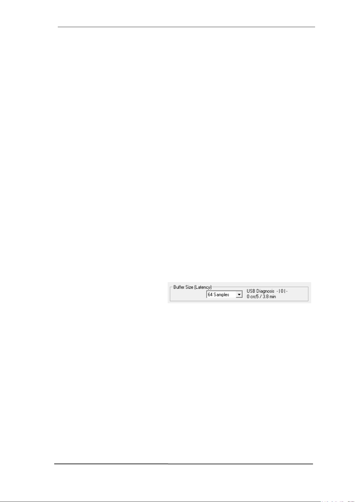
User's Guide Digiface AES © RME
95
AD/DA Offset under ASIO and OS X: ASIO (Windows) and Core Audio (Mac OS X) allow for the
signalling of an offset value to correct buffer independent delays, like AD- and DA-conversion or
the Safety Buffer described below. An analog loopback test will then show no offset, because the
application shifts the recorded data accordingly. Because in real world operation analog record
and playback is unavoidable, the drivers include an offset value matching the Digiface's converter
delays.
Therefore, in a digital loopback test a negative offset of about 3 ms occurs. This is no real problem, because this way of working is seldom, and usually the offset can be compensated manually
within the application. Additionally, keep in mind that even when using the digital I/Os usually at
some place an AD- and DA-conversion is involved (no sound without...).
Safety Buffer
An additional small safety buffer on the playback side has proven to be very efficient and useful.
It is therefore implemented in all RME interfaces. Under Windows the Digiface AES uses a fixed
additional buffer of 32 samples, under Mac 24 samples, which is added to the current buffer size.
The main advantage is the ability to use lowest latency at highest CPU loads. Furthermore, the
fixed buffer does not add to the latency jitter (see Tech Info), the subjective timing is extraordinary.
Core Audio's Safety Offset
Under OS X, every audio interface has to use a so called Safety Offset on record and playback,
otherwise Core Audio won't operate click-free. The Digiface uses a Safety Offset of 24 samples.
This offset is signalled to the system, and the software can calculate and display the total latency
of buffer size plus AD/DA offset plus 2 x Safety Offset plus Safety Buffer for the current sample
rate. The option Short Safety Offset in the Settings dialog reduces this to 12 samples each.
38.3 USB Audio
USB audio is in several ways different from PCI based audio interfaces. A good performance and
click-free operation at a low buffer size are indeed possible on current computers. However, using
older computers a simple stereo playback will begin to cause a CPU load of more than 30%.
A computer blocked for a short time – no matter if ASIO or WDM – will lose one or more data
packets. Such problems can only be solved by increasing the buffer size (latency).
The Digiface features a unique data
checking, detecting errors during transmission via USB and displaying them in
the Settings dialog.
Additionally the Digiface provides a special mechanism to continue recording and playback in
case of drop-outs, and to correct the sample position in real-time.
Best USB 2 performance is achieved by connecting the Digiface AES to its own bus, which should
be no big problem as most USB 2.0 interfaces are a double bus design. A check in the Device
Manager can be done as follows:
Connect the Digiface AES to a USB 2 port
Start the Device Manager, View set to Devices by Connection
Select ACPI x86-based PC, Microsoft ACPI-Compliant System, expand PCI Bus
This branch normally includes two entries of a USB2 Enhanced Host Controller. A USB Root Hub
can be seen, which then connects all USB devices, including the Digiface AES. By reconnecting
to a different port this view shows at which of the two controllers the Digiface AES is connected.
With multiple devices it can be checked if they are connected to the same controller.

96
User's Guide Digiface AES © RME
Furthermore this information can be used to operate an external USB drive without disturbing the
Digiface AES, by simply connecting the drive to the other controller.
Especially with notebooks it can happen that all internal devices and all the sockets/ports are
connected to the same controller, with the second controller not used at all. In that case all devices
have to use the same bus and will interfere with each other.
38.4 DS - Double Speed
Sample rates above 48 kHz were not always taken for granted, and are still not widely used
because of the CD format (44.1 kHz) dominating everything. Before 1998 there were no receiver/transmitter circuits available that could receive or transmit more than 48 kHz. Therefore a
work-around was used: instead of two channels, one AES line only carries one channel, whose
odd and even samples are being distributed to the former left and right channels. By this, you get
the double amount of data, i. e. also double sample rate. Of course in order to transmit a stereo
signal two AES/EBU ports are necessary then.
This transmission mode is called Double Wire in the professional studio world, and is also known
as S/MUX (Sample Multiplexing) in connection with the multichannel ADAT format.
Because the ADAT interface does not allow for sampling frequencies above 48 kHz (a limitation
of the interface hardware), the Digiface AES automatically uses Sample Multiplexing in DS mode.
One channel's data is distributed to two channels. As the transmission of double rate signals is
done at standard sample rate (Single Speed), the ADAT outputs still deliver a 44.1 kHz or 48 kHz
carrier.
38.5 QS – Quad Speed
Due to the small number of available devices that use sample rates up to 192 kHz, but even more
due to a missing real world application (CD...), Quad Speed has had no broad success. An implementation of the ADAT format as double S/MUX (S/MUX4) results in only two channels per
optical output. Devices using this method are few.
In earlier times the transmission of 192 kHz had not been possible via Single Wire, so once again
sample multiplexing was used: instead of two channels, one AES line transmits only one half of
a channel. A transmission of one channel requires two AES/EBU lines, stereo requires even four.
This transmission mode is being called Quad Wire in the professional studio world.
Because the ADAT interface does not allow for sampling frequencies above 48 kHz (a limitation
of the interface hardware), the Digiface AES automatically uses Sample Multiplexing in QS mode.
One channel's data is distributed to four channels. As the transmission of quad rate signals is
done at standard sample rate (Single Speed), the ADAT outputs still deliver a 44.1 kHz or 48 kHz
carrier.

User's Guide Digiface AES © RME
97
38.6 SteadyClock FS
RME’s SteadyClock technology guarantees an excellent performance in all clock modes. Its
highly efficient jitter suppression refreshes and cleans up any clock signal. Thanks to the efficient
jitter suppression, the AD- and DA-conversion always operates on highest sonic level, being completely independent from the quality of the incoming clock signal.
RME realizes modern circuit designs like hi-speed digital synthesizer, digital PLL and 800 MHz
sample rate cost- and space-saving right within the FPGA. Combined with analog and digital
filtering a professional clock technology is created that is second to none. Also SteadyClock reacts
quite fast compared to other techniques. It locks in fractions of a second to the input signal, follows
even extreme varipitch changes with phase accuracy, and locks directly within a range of 28 kHz
up to 200 kHz.
The analysis of so-called interface jitter
with the help of an oscilloscope shows
how it works. The screenshot shows a
very jittery SPDIF signal with about 50
ns jitter (top graph, yellow). SteadyClock turns this signal into a clean clock
signal with less than 2 ns jitter (lower
graph, blue). The signal processed by
SteadyClock is not only used internally,
but also used to clock the digital outputs. Therefore the refreshed and jittercleaned signal can be used as reference clock without hesitation.
The so-called sampling jitter, usually in the range of picoseconds, is also very low in the Digiface
AES. One way to show this is to send out a specially modulated 11.025 kHz sine from the analog
output, then analyze the sampled result. Jitter products are shown in the measurement as symmetrical sidebands, like narrow needles. SteadyClock does not show obvious sidebands. Also
remarkable is the identical performance when using internal or external clock – a typical SteadyClock feature. Check RME’s YouTube channel for a video showing and explaining such measurements.
The further improved Steady-
Clock FS technology attenuates
even lowest frequency jitter (>1
Hz), and provides an even
higher jitter suppression at lowest self-jitter. Of course, this can
also be proven by measurement. In this measurement, an
AES signal with 0 ns (reference), 100 ns and 400 ns (!) jitter is applied, and the modulation frequency is swept in the
range 20 Hz to 20 kHz in each
case. At 50 Hz, approximately
210 ps can be detected, corresponding to a jitter suppression
of > 65 dB. This is simply fantastic for such low frequencies.

98
User's Guide Digiface AES © RME
39. Diagrams
39.1 Block Diagram Digiface AES

User's Guide Digiface AES © RME
99
39.2 Connector Pinouts
TRS jacks of analog input / output
The stereo 1/4" TRS jacks of the rear analog inputs and outputs are wired according to international standards:
Tip = + (hot)
Ring = – (cold)
Sleeve = GND
The servo balanced input and output circuitry allows to use monaural TS jacks (unbalanced) with
no loss in level. This is the same as when using a TRS-jack with ring connected to ground.
XLR jacks of analog inputs and outputs
The XLR jacks are wired according to international standards:
1 = GND (shield)
2 = + (hot)
3 = - (cold)
The electronic driver circuit of the XLR outputs does not operate servo-balanced! When connecting unbalanced equipment, make sure pin 3 of the XLR output is not connected. A connection to ground will cause higher THD (distortion)!
TRS Phones jack
The analog monitor outputs on the front are
accessible through stereo 1/4" TRS jacks.
This allows a direct connection of headphones. In case the output should operate
as Line output, an adapter TRS plug to RCA
phono plugs, or TRS plug to TS plugs is required.
The pin assignment follows international
standards. The left channel is connected to
the tip, the right channel to the ring of the
TRS jack/plug.
!

100
User's Guide Digiface AES © RME
 Loading...