

Page 1
User's Guide
Analog Expansion Board
for DIGI96/8 Series
and Hammerfall Serie
4/8 Channels, 24 Bit
Page 2

Contents
1 Introduction..................................................................3
2 Package Contents .......................................................3
3 Hardware Requirements..............................................3
4 Technical Specifications..............................................3
5 Hardware Installation...................................................4
6 Alternative Installation..................................................5
7 Operation and Usage...................................................6
8 Channel Routing AEB4-O............................................6
9 Pin assignment of the TRS jacks ................................7
10 Warranty......................................................................7
11 Appendix......................................................................7
User's Guide AEB4/8-O
2
Page 3

1. Introduction
Thank you for choosing the RME AEB technology. The Analog Expansion Boards add 4 or 8
analog outputs in professional quality to RME's digital audio cards. Level adjustment +4 dBu/-10
dBV, 107 dBA SNR and highest suppression of PC-noise guarantee perfect sound quality.
2. Package Contents
Please ensure that all the following parts are included in the AEB's packaging box:
• Analog Expansion Board
• 1 Clock cable 3-core
• 1 Data cable 2-core
• 1 Cable adapter 5 ¼" to 2 x 3,5"
• 1 Set of nuts
• Manual, drill template
3. Hardware Requirements
AEBs can only be used with RME cards.
DIGI96 Series
AEBs use the internal ADAT interface of the DIGI cards. Therefore they do not work with the
DIGI96 (which did not support ADAT).
One AEBx-I and one AEBx-O can be connected and operated simultaneously, in all possible
combinations.
Hammerfall Series
An operation with the Hammerfall or Hammerfall Light requires board revision 1.5 or higher,
because the internal connectors ADAT1Out and ADAT2Out were not implemented in earlier
versions.
One AEBx-I and two AEBx-O can be connected and operated simultaneously, in all possible
combinations.
4. Technical Specifications
• Output AEB4-O: 4 x 1/4" TRS jack, servo balanced
• Output AEB8-I: 4 x 1/4" TRS jack, unbalanced
• Dynamic ratio: 103 dB (RMS unweighted), 106 dBA
• THD+N: -95 dB (0.0017 %)
• Frequency response -0.1 dB: 10 Hz - 21 kHz
• Output level for 0 dBFS @ +4 dBu: +12 dBu
• Output level for 0 dBFS @ -10 dBV: +2 dBV
• Crosstalk: > 110 dB
• Supported sample rates: 44.1 kHz, 48 kHz
• Output impedance: 75 Ohm
• Power supply uses 3.5" floppy connector, 12 V/5 V DC, 190 mA
• Standard bracket, board dimensions AEB4: 85 x 95 mm, AEB8: 120 x 95 mm
User's Guide AEB4/8-O
3
Page 4
5. Hardware Installation
Important: Switch off the computer and remove the power cable from the power supply before
fitting the AEB.
1. Disconnect the power cable and all other cables from the computer.
2. Remove the PC housing; further information on how to do this can be obtained from your
computer´s instruction manual.
3. Neutralize the static build up by touching the PC metal-chassis before unpacking the AEB
from the protective bag.
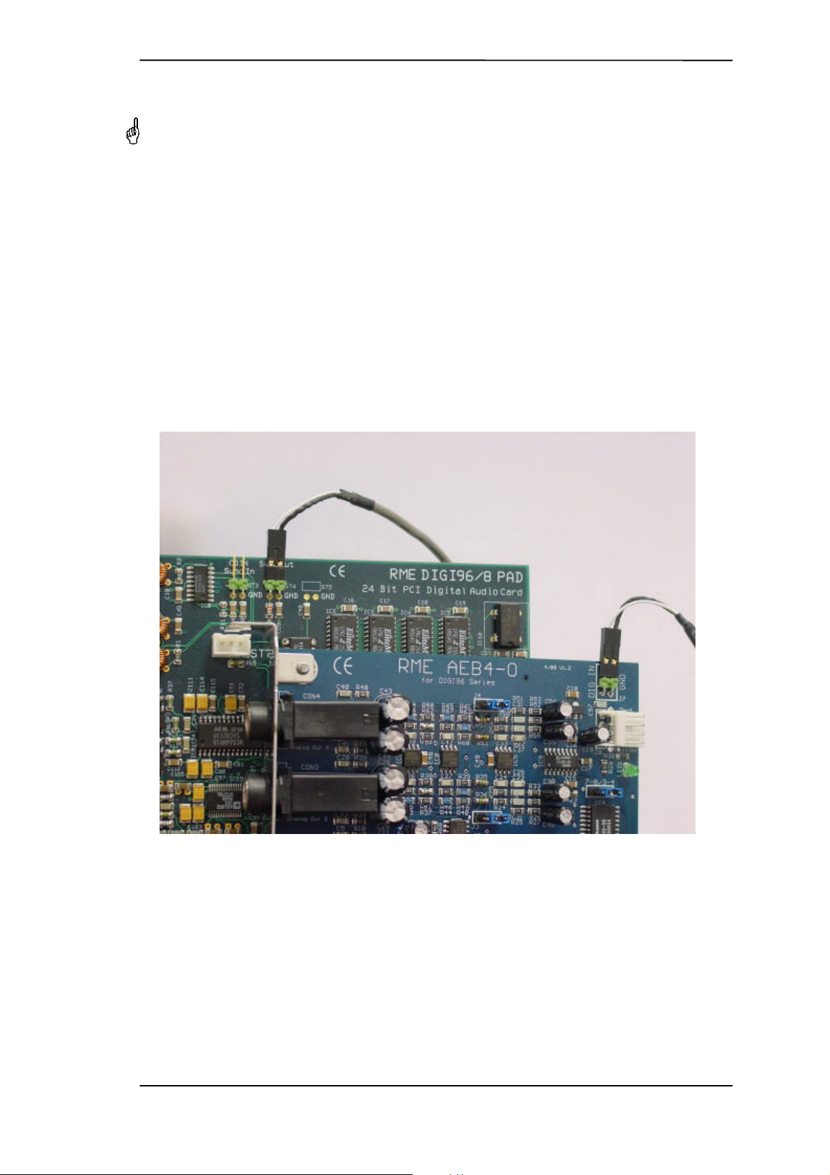
4. Connect the AEB's DIG IN and the DIGI's Sync-Out (Hammerfall: ADAT1/2 Out) using the
supplied 2-wire cable. Watch out for correct polarity: The shield wire is black, and must be
connected to the pin marked GND on the DIGI (the right one).
5. Connect power supply: The AEB uses a floppy power connector (3,5"). In case no such connector is available use the supplied adapter cable to connect the AEB to any free 5 ¼" power
connector.
6. Insert the AEB into a free slot, press and fasten the screw. The AEB needs no slot on the
motherboard, but includes a stabilizing edge, which fits in both PCI and ISA slots.
7. Re-insert the DIGI in a PCI slot and fasten the screw.
8. Re-place the PC housing and tighten the screws.
9. Re-connect the power cable and all other cables/connections.
Connecting an AEBx-O to a DIGI96/8 PAD
User's Guide AEB4/8-O
4
Page 5
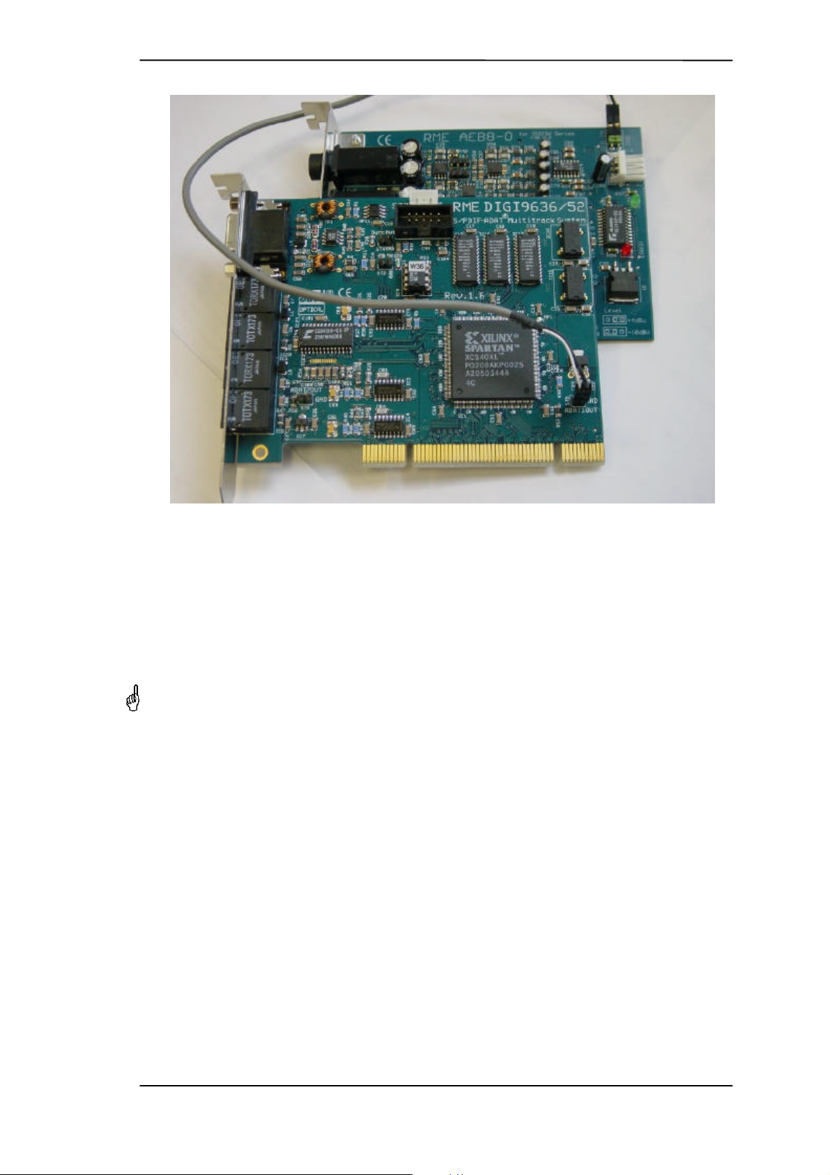
Connecting an AEBx-O to a Hammerfall
6. Alternative Installation
Installation is done comfortably as described using the attached bracket. Alternatively it is possible to mount the AEB at a different place inside the computer using the supplied nuts. This requires to drill 4 holes into the housing.
RME does not accept claims for damages of any kind when installing the AEB in this
way! Modifications to the housing should be done by qualified technicians only, and
only after having removed all components from the housing (danger of short circuit by
metal splinter etc).
1. Remove the bracket from the AEB (2 screws).
2. Carefully check that the desired location offers a flat plane, is free from any voltage carrying
devices or cables, and that the AEB does not get in contact with other devices even when the
housing is closed.
3. Please note that the lenght of the supplied cables does not allow any distance to the DIGI
card.
4. Drill 4 holes, diameter 0.5" (13 mm), distance of 0.75" (19.05 mm) each, at the desired place
(see drill template).
5. Fit the AEB into the holes and fix it with the supplied nuts.
User's Guide AEB4/8-O
5
Page 6
7. Operation and Usage
The AEB works like any other device having an ADAT input, but is located inside your computer.
Please note that the AEB requires the DIGI96/8 to send the output format 'ADAT'. Therefore
using the DIGI96/8 series 'Force ADAT' should be activated in the DIGI's Settings dialog.
Two LEDs on the AEBx-O serve as useful error indication. The green LED is lit when the power
supply is present. The red LED is lit when the digital input signal is no ADAT format or not reliable. This will happen when the card is still sending SPDIF, or no signal at all is present at the
connector DIG IN.
8. Channel Routing AEB4-O
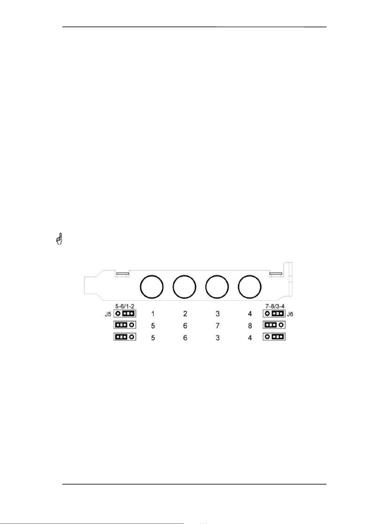
The AEB4-O is designed for maximum flexibility. Jumpers J5 and J6 allow to route digital channels 1/2 or 5/6 to analog output 1 and 2, and digital channels 3/4 or 7/8 to analog output 3 and 4.
The jumper setting is printed on the board.
In combination with DIGI96/8 PRO, PST or PAD six analog outputs are available, due to the
cards own stereo analog output.
The default setting of the jumper J5/J6 is 1/2 and 3/4. In this case the track button of the DIGI's
analog output should be set to 5/6 or 7/8, to gain 6 different and independent analog outputs.
In case the DIGI's analog output shall playback channel 1/2 and the AEB channels 3/4 and 5/6,
the jumpers have to be set accordingly.
Please note that in this case the channel order according to the jacks seems to be swapped
(jack 1 plays channel 5, jack 2 channel 6, jack 3 channel 3 and jack 4 channel 4).
User's Guide AEB4/8-O
6
Page 7
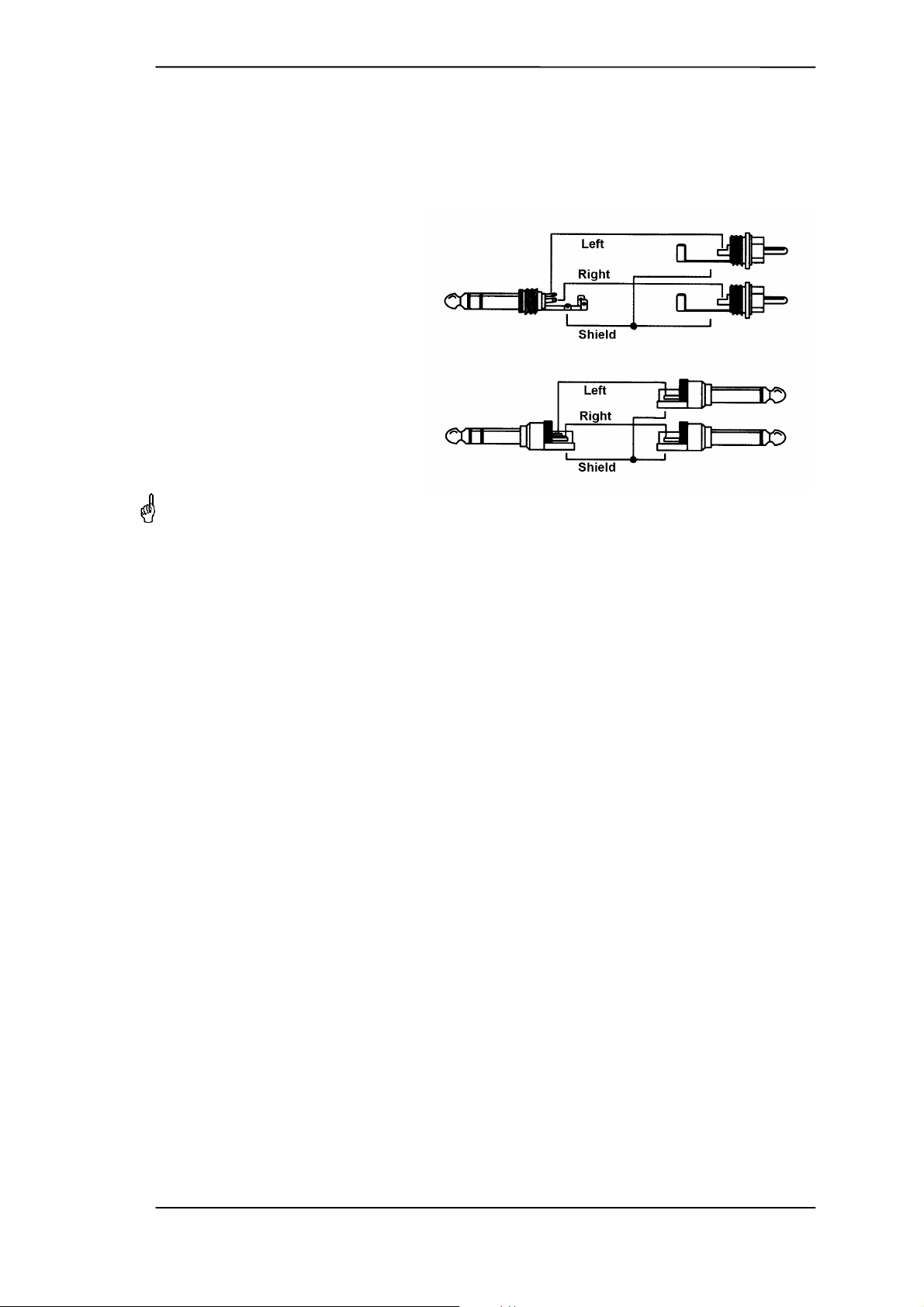
9. Pin assignment of the TRS jacks
The analog outputs are accessible through stereo ¼" TRS jacks.
The AEB4-O is fitted with electronically balanced, single channel outputs (+ = tip). The servo
balanced output stage allows to use monaural TS jacks (unbalanced) with no loss in level.
The AEB8-O is fitted with unbalanced
stereo outputs. Use an adapter TRS
plug to coaxial (phono) plugs, or TRS
plug to TS plugs (see drawing to the
right) for connection to external
equipment. We recommend to use so
called 'insert' cables.
The pin assignment follows international standards. The left channel is
connected to the tip, the right channel
to the ring of the TRS jack/plug.
Tip: Up to 4 headphones can be connected directly to the AEB8-O!
10. Warranty
Each individual AEB undergoes comprehensive quality control and a complete test in a PC environment at RME before shipping. The usage of high grade components allows us to offer a full
two year warranty. We accept a copy of the sales receipt as valid warranty legitimation.
RME’s replacement service within this period is handled by the retailer. If you suspect that your
card is faulty, please contact your local retailer. The warranty does not cover damage caused by
improper installation or maltreatment - replacement or repair in such cases can only be carried
out at the owner’s expense.
RME does not accept claims for damages of any kind, especially consequential damage. Liability is limited to the value of the AEB. The general terms of business drawn up by Synthax OHG
apply at all times.
11. Appendix
RME news, driver updates and further product information are available on our website:
http://www.rme-audio.com
If you prefer to read the information off-line, you can load a complete copy of the RME website
from the RME Driver CD (in the \rmeaudio.web directory) into your browser.
User's Guide AEB4/8-O
7
Page 8

Trademarks
All trademarks and registered trademarks belong to their respective owners. RME, DIGI96, SyncAlign and ZLM are registered trademarks of RME Intelligent Audio Solutions. Alesis and ADAT
are registered trademarks of Alesis Corp. ADAT optical is a trademark of Alesis Corp. Microsoft,
Windows, Windows 98/NT/2000 are trademarks of Microsoft Corp.
Copyright Matthias Carstens, 4/2001. Version 1.2
Current driver version: W98: 4.96, NT 3.85, W2k: 1.36
Although the contents of this User’s Guide have been thoroughly checked for errors, RME can not guarantee that it is
correct throughout. RME does not accept responsibility for any misleading or incorrect information within this guide.
Lending or copying any part of the guide or the RME drivers CD, or any commercial exploitation of these media without
express written permission from RME Intelligent Audio Solutions is prohibited. RME reserves the right to change specifications at any time without notice.
CE
This device has been tested and found to comply with the limits of the European Council Directive on the approximation of the laws of the member states relating to electromagnetic compatibility (EMVG) according to EN 55022 class B and EN50082-1.
FCC Compliance Statement
Certified to comply with the limits for a Class B computing device according to subpart J or part
15 of FCC rules. See instructions if interference to radio reception is suspected.
FCC Warning
This equipment has been tested and found to comply with the limits for a Class B digital device,
pursuant to part 15 of the FCC rules. These limits are designed to provide reasonable protection
against harmful interference in a residential installation.
This device complies with part 15 of FCC rules. Operation is subject to the following two conditions:
1. This device may not cause harmful interference
2. This device must accept any interference received, including interference that may cause
undesired operation.
However, there is no guarantee that interference will not occur in a particular installation. If this
equipment does cause harmful interference to radio or television reception, which can be determined by turning the equipment off and on, the user is encouraged to try to correct the interference by one or more of the following measures:
• Reorient or relocate the receiving antenna
• Increase the seperation between the equipment and receiver
• Connect the equipment into an outlet on a circuit different from that to which the receiver is
connected
• Consult the dealer or an experienced radio/TV technician for help.
In order for an installation of this product to maintain compliance with the limits for a Class B
device, shielded cables must be used for the connection of any devices external to this product.
User's Guide AEB4/8-O
8
 Loading...