


User’s Guide
ADI-2/4 Pro SE
Conversion done right - again
2 Channels Analog / Digital Converter
4 Channels Digital / Analog Converter
AES / ADAT / SPDIF Interface
32 Bit / 768 kHz Digital Audio
USB 2.0 Class Compliant
2 Extreme Power Headphone Outputs
Digital Signal Processing
Advanced Feature Set
Extended Remote Control
32 Bit / 768 kHz
Hi-Res Audio
SteadyClock FS
SyncCheck

2
User’s Guide ADI-2/4 Pro SE - v 1.3
General
1 Introduction ............................................................... 5
2 Package Contents ..................................................... 5
3 System Requirements............................................... 5
4 Brief Description and Characteristics ..................... 6
5 First Usage - Quick Start
5.1 Connectors and Controls ........................................ 7
5.2 Quick Start............................................................... 8
5.3 Operation at the unit ................................................ 8
5.4 Overview Menu Structure ........................................ 9
5.5 Software Operation – ADI-2 Remote .................... 10
5.6 Playback ................................................................ 11
5.7 Analog Recording .................................................. 11
5.8 Digital Recording ................................................... 11
6 Power Supply ........................................................... 12
7 Firmware Update ..................................................... 12
8 Features Explained
8.1 Extreme Power Headphones Outputs .................. 13
8.2 Dual Phones Outputs ............................................ 14
8.3 5-band Parametric EQ .......................................... 14
8.4 Bass / Treble ......................................................... 15
8.5 Loudness ............................................................... 15
8.6 SRC (Sample Rate Conversion) ........................... 16
8.7 Crossfeed .............................................................. 16
8.8 RIAA Mode ............................................................ 17
8.9 DSP Limitations ..................................................... 18
Basic and Stand-Alone Operation Details
9 RME Multi-Remote Control (MRC)
9.1 Keys and Functions .............................................. 20
9.2 Other Remote Controls ........................................ 21
10 Front Panel Controls
10.1 Keys ..................................................................... 21
10.2 Encoders .............................................................. 21
11 VOL ........................................................................... 22
12 I/O
12.1 Analog Input
12.1.1 Settings ........................................................ 23
12.1.2 Parametric EQ .............................................. 24
12.2 Line Output 1/2
12.2.1 Settings ........................................................ 24
12.2.2 Bass/Treble .................................................. 26
12.2.3 Loudness ...................................................... 26
12.3 Phones Output 1/2 and 3/4 .................................. 27
13 EQ ............................................................................. 27
14 SETUP
14.1 Options
14.1.1 SPDIF / Remap Keys ................................... 29
14.1.2 Expert Settings ............................................. 30
14.1.2 Clock ............................................................ 31
14.1.3 Device Mode / DSD ...................................... 31
14.1.4 Phones ......................................................... 31
14.1.5 Display .......................................................... 32
14.2 Load/Store all Settings ......................................... 33

User’s Guide ADI-2/4 Pro SE – v 1.3
3
15 Top Screens
15.1 Global Level Meter ............................................... 34
15.2 Analyzer ............................................................... 34
15.3 State Overview ..................................................... 35
15.4 Dark Volume ........................................................ 36
16 Warning Messages ................................................. 37
17 Modes
17.1 Auto ...................................................................... 39
17.2 Preamp ................................................................ 40
17.3 AD/DA Converter ................................................. 41
17.4 USB ...................................................................... 42
17.4.1 Stereo Mode ................................................ 42
17.4.2 Multichannel Mode ....................................... 43
17.4.3 Loopback Analog Out to USB Record ......... 44
17.5 Digital Through ..................................................... 45
17.6 DAC ..................................................................... 46
18 Balanced Phones Mode .......................................... 47
19 DSD Operation
19.1 General ................................................................ 48
19.2 DSD Playback ...................................................... 48
19.3 DSD Record ......................................................... 49
19.4 DSD Level Meter.................................................. 50
19.5 Beyond… ............................................................. 50
Inputs and Outputs
20 Analog Inputs .......................................................... 52
21 Analog Outputs
21.1 General ................................................................ 52
21.2 Line Out TRS 1/2 (3/4) ......................................... 53
21.3 Line Out XLR 1/2 ................................................. 53
21.4 PH Out 1/2 ........................................................... 53
21.5 PH Out 3/4 ........................................................... 54
22 Digital Connections
22.1 AES ...................................................................... 54
22.2 SPDIF .................................................................. 55
22.3 ADAT ................................................................... 56
Installation and Operation - Windows
23 Driver Installation .................................................... 58
24 Configuring the ADI-2/4 Pro SE
24.1 Settings Dialog ..................................................... 59
24.2 Clock Modes - Synchronization ........................... 60
25 Operation and Usage
25.1 Playback .............................................................. 60
25.2 DVD Playback (AC-3 / DTS) ................................ 61
25.3 Multi-client Operation ........................................... 61
25.4 Multi-interface Operation ..................................... 61
25.5 ASIO .................................................................... 62
26 DIGICheck Windows ............................................... 62
Installation and Operation – Mac OS X
27 General ..................................................................... 64
27.1 Configuring the ADI-2/4 Pro SE ........................... 64
27.2 Clock Modes - Synchronization ........................... 65
27.3 Multi-interface Operation ..................................... 65

4
User’s Guide ADI-2/4 Pro SE - v 1.3
28 DIGICheck Mac ........................................................ 65
Installation and Operation – iOS
29 General ..................................................................... 68
30 System Requirements............................................. 68
31 Setup ........................................................................ 68
32 Supported Inputs and Outputs .............................. 68
Technical Reference
33 Technical Specifications
33.1 Analog Inputs ....................................................... 70
33.2 Analog Outputs .................................................... 70
33.3 Digital Inputs ........................................................ 71
33.4 Digital Outputs ...................................................... 72
33.5 Digital ................................................................... 72
33.6 General................................................................. 72
33.7 Connector Pinouts ................................................ 73
34 Technical Background
34.1 Lock and SyncCheck ........................................... 74
34.2 Latency and Monitoring ........................................ 75
34.3 USB Audio (Windows) .......................................... 76
34.4 M/S-Processing .................................................... 77
34.5 Emphasis ............................................................. 78
34.6 True Balanced Phones Mode .............................. 79
34.7 Crosstalk at the TRS Phones Output ................... 81
34.8 SteadyClock FS ................................................... 83
34.9 ADI-2/4 Pro SE as Measurement Frontend ......... 84
34.10 Noise Level in Hi-Speed Modes ........................... 86
34.11 AD Impulse Responses........................................ 87
34.12 DA Impulse Responses........................................ 88
34.13 Frequency Response Preamp Mode (AD/DA) ..... 90
34.14 AD Frequency Response and Filter Curves ........ 91
34.15 DA Filter Curves @ 44.1 kHz ............................... 91
34.16 Loudness .............................................................. 92
34.17 Bass / Treble ........................................................ 92
34.18 Distortion Measurements Analog I/O ................... 93
34.19 Crosstalk Phones Balanced / Unbalanced........... 94
34.20 Extreme Power Charts ......................................... 95
34.21 Phones Distortion Comparison ............................ 96
34.22 Measurements Distortion vs Power ..................... 96
34.23 Impedance based Level Meters PH 1-4............... 98
34.24 Digital Volume Control ......................................... 99
34.25 Bit Test ............................................................... 101
34.26 Digital DC Protection .......................................... 102
34.27 Operation in the Hi-Fi Environment .................... 104
34.28 Using a Turntable ............................................... 108
34.29 Block Diagram .................................................... 110
Miscellaneous
35 Accessories ........................................................... 112
36 Warranty ................................................................. 112
37 Appendix ................................................................ 113
38 Declaration of Conformity .................................... 114

User’s Guide ADI-2/4 Pro SE – v 1.3
5
1. Introduction
RME’s ADI-2 Pro was first released in 2016 and has been a true milestone in many ways. Looking
at the multitude of AD/DA converters, USB DACs and dedicated headphone amps available, RME
developers felt they all lacked obvious features that are unavoidable to enjoy operation as well as
when listening to music. And while many of those devices claim to use the latest state-of–the–art
whatsoever converter chip, serious magazines and RME staff were repeatedly disappointed to
find that in the end the stellar technical data published in ads and datasheets were nowhere to be
found.
With the ever growing popularity of headphones and latest AD/DA chips pushing technical data
further, the ADI-2 Pro convinced with the industry’s biggest footprint per feature ratio, with specs
that were as real as RME‘s reputation, a feature set that was unheard of, useful features that for
unknown reasons no one else implemented, and two extremely powerful headphone outputs -
the new reference in accuracy and dynamic range.
Based on the feedback of our customers and the developers’ desire for an ADI-2 with more features, the ADI-2/4 Pro Special Edition was created, which in many details is even more flexible
and powerful than the Pro due to significantly increased hardware effort. But is still an ADI-2 Pro
- a multitude of devices compressed in one housing, with simple and mostly automated operation:
A high-end AD/DA converter in professional studio quality
A double headphone amplifier in true high-end quality
A USB DAC like no other - the most versatile and capable one around
A high-end AD/DA frontend and headphone amp for iPad and iPhone
An AD/DA frontend for measurement systems at up to 768 kHz sample rate
A multi-format converter (AES, SPDIF, ADAT) with monitoring
An SPDIF/ADAT playback system
A DSD record and playback solution
A vinyl player digitizing solution on highest level
All there is left to say now is: Enjoy!
2. Package Contents
ADI-2/4 Pro SE
Remote control with battery (MRC)
Manual
External switched power supply with IEC socket, lockable connector, DC 12 V 40 W
Power cord
Digital breakout cable AES/SPDIF (BO968)
USB 2 cable, 1.8 m (6 ft)
Quick start guide
3. System Requirements
General:
Power supply 12V DC, 2 A or up
For computer based operation:
Windows 7 or up, Intel Mac OS X (10.6 or up)
1 USB 2.0 port or USB 3 port
Computer with at least Intel Core i5 CPU
For iOS based operation:
iPhone or iPad with iOS 7 or up
Dock or Lightning to USB adapter

6
User’s Guide ADI-2/4 Pro SE - v 1.3
4. Brief Description and Characteristics
The ADI-2/4 Pro SE is a 2-channel analog input to digital and 4-channel digital to analog output
converter in a half-rack (9.5") enclosure of 1 U height. Latest 32 bit / 768 kHz converters offer up
to 123 dBA signal to noise ratio. This value is not only printed in the brochure – it is what the unit
achieves in real-world operation.
Reference class tech specs throughout are combined with an unprecedented feature set. A powerful DSP adds all kinds of useful audio processing, including 5-band parametric EQ, fast
Bass/Treble adjustment, Crossfeed, and a new concept in Loudness sound control.
Operation is quick and easy through 3 encoders with push button function and 4 more buttons to
access dedicated menus. The unit remembers all current settings, even the menu position. Additionally the unit’s whole setup as well as equalizer settings can be stored under individual names.
A high resolution IPS panel for the graphical operation surface eases operation even more, and
displays further functions provided by the DSP, namely Peak level meters, a 30-band analyzer in
DIGICheck biquad filter technology, and a State Overview screen listing the current states of
SPDIF, AES, USB and clock.
The digital inputs SPDIF coaxial (or optical) and AES operate simultaneously. An additional Sample Rate Converter decouples the SPDIF or AES clock for even simpler setups, and also supports
up- and down-sampling of the input signals. SPDIF optical also supports 2 channels of ADAT
operation, at up to 192 kHz.
When used as USB interface, the Class Compliant UAC 2 mode can be set to Stereo or Multichannel. Multi-channel mode turns the ADI-2/4 Pro SE into a 6 channel (Analog 1/2, AES, SPDIF)
record and 8 channel (Analog 1/2/3/4, AES, SPDIF) playback audio interface, that even works as
iPad front-end up at up to 192 kHz sample rate. In stereo mode sample rates up to 768 kHz are
supported, for high resolution recordings or PCM, DXD and DSD record/playback.
The servo balanced analog inputs and dedicated balanced and unbalanced outputs are fitted with
both XLR and 1/4" TRS jacks. The unit uses a fully balanced and DC-coupled circuit design, for
highest phase accuracy at lowest roll-off. The only capacitors in the whole signal path, non-polar
MUSE audio capacitors from Nichicon, reside directly at the input of the unit (external DC protection).
The two Extreme Power headphone outputs provide reference sound and headroom. RME’s True
Balanced mode, one more of an endless feature list, realizes balanced phones operation independent from the XLR outputs.
To maintain the full dynamic range within the best operating level, discrete 5-stage reference level
settings were realized for maximum dynamic range (+1, +7, +13, +19, +24 dBu). Also available
are 0 to +6 dB digital trim for fine input sensitivity adjustment in steps of 0.5 dB.
The ADI-2/4 Pro SE supports sample rates between 44.1 kHz and 768 kHz. Furthermore, RME's
SteadyClock FS guarantees exceptional performance in all clock modes. Thanks to a highly efficient jitter suppression, the AD- and DA-conversion always operates on highest sonic level, being
completely independent from the quality of the incoming clock signal.
The ADI-2/4 Pro SE shines in both studio and home usage. Its click- and noise-free on/off operation and a comfortable, illuminated standby button add to the soft, modern desktop design.
Mobile and galvanically separated usage is possible through a 12V connector for easy battery
connection.

User’s Guide ADI-2/4 Pro SE – v 1.3
7
5. First Usage – Quick Start
5.1 Connectors and Controls
The front of the ADI-2/4 Pro SE has 3 hi-precision rotary encoders with push function, 4 buttons,
a standby power button, a high resolution IPS display, and two TRS headphone outputs plus one
Pentaconn.
The output channels 1/2 and 3/4 feed two phones outputs via two independent Extreme Power
driver circuits, optimized for both high and low impedance headphones. Their unbalanced output
signal is of highest quality. With 122 dBA SNR there is no audible hum and noise at those outputs.
Balanced phones mode is automatically activated by using the Pentaconn jack on the front.
In case a phones output is to be used as line output, an adapter TRS plug to RCA phono plugs,
or TRS plug to two TS plugs is required.
The rear of the ADI-2/4 Pro SE has 2 servo-balanced analog inputs on combo XLR/TRS sockets,
2 TRS sockets as impedance-balanced outputs, 2 XLR sockets as electronically balanced outputs, TOSLINK optical I/O, a USB socket, a Trigger output and a lockable power socket. An included breakout cable is connected to the DB-9 socket and provides AES I/O via XLR and SPDIF
coaxial I/O via RCA.
The ADI-2/4 Pro SE has two analog line inputs that can operate with levels up to +24 dBu. The
electronic input stage uses a servo balanced design which handles unbalanced and balanced
signals correctly, automatically adjusting the level reference.
When using unbalanced cables with the XLR inputs, pin 3 of the XLR jack should be connected to ground. Otherwise noise may occur, caused by the unconnected negative input of
the balanced input.
The analog inputs 1/2 include 6 dB digital gain control via DSP, and a choice of +1 dBu, +7 dBu,
+13 dBu, +19 dBu or +24 dBu as reference level, performed in the analog domain.
The short circuit protected, low impedance XLR line outputs do not operate servo balanced!
When connecting unbalanced equipment via XLR, make sure pin 3 of the XLR output is not
connected. A connection to ground might cause a decreased THD (higher distortion) and
increased power consumption!
Optical I/O (TOSLINK): The unit automatically detects SPDIF or ADAT input signals. The optical
output can operate as ADAT or SPDIF output, depending on the current setting in the Setup menu
(Options, SPDIF / Remap Keys). Note that only channels 1/2 from the ADAT stream can be accessed. SMUX and SMUX4 (up to 192 kHz) are still supported.
USB 2.0: Standard USB socket for connection to the computer. The ADI-2/4 Pro SE operates as
Class Compliant device, in either 2-channel or 8-channel mode (configured in Setup). It can be
directly used with Mac OS X and iOS (iPad, iPhone). For Windows the RME MADIface series
driver adds WDM and ASIO.
Socket for power connection. This socket supports locking type jacks as found on the included
RME DC power supply. After inserting the connector carefully turn it by 90° so that it locks. If the
unit turns off easily when moved then the connector is NOT fully inserted into the socket!
Trigger Out provides a 12 V switching signal via 3.5 mm mono jack plug, which can be used e.g.
to switch power amps with Trigger In on and off together with the ADI-2/4 Pro. Trigger Out passes
on the actual voltage of the power supply, therefore more or less than 12 V may occur. A maximum of 150 mA is available for external switching operations.
!
!

8
User’s Guide ADI-2/4 Pro SE - v 1.3
5.2 Quick Start
Connect the unit to the included power supply and push the Standby button to start. The ADI-2/4
Pro SE ships with Basic Mode Auto activated (SETUP – Options – Device Mode / DSD – Basic
Mode). The input selection for SPDIF (coaxial or optical), and the source selection for Phones
Out 3/4 are also set to Auto, the SRC is activated for the SPDIF input. With Auto active the unit
will turn into different modes depending on connected cables:
Preamp: Analog in to Analog out (internal digital out to in). This mode is active when no digital
input signal and no USB is detected.
AD/DA: Converter Mode, analog in to all digital outs, digital in to all analog outs. This mode
becomes active as soon as a digital signal is attached. This signal will also become the signal
source. In case more than one digital signal is found the user has to manually select the source
to be monitored. The SRC is active as default and assigned to SPDIF. Clock mode is slave to
AES in, but will adapt to the detected source (Auto).
USB: or interface mode (also USB DAC). If USB is detected all inputs are routed to USB, all
outputs are fed from USB. USB has priority over the converter mode. In Setup the unit can be
configured as 2- or 8-channel device. In most cases 2-channel will be the better choice.
USB can be manually overridden by selecting a different mode. This will change the I/O routing,
but not disable USB itself. All inputs are still available via USB, outputs 3/4 can playback USB. In
all modes except Basic Mode DAC output PH 3/4 is freely configurable, any possible source can
be monitored independently from outputs 1/2.
The unit remembers all settings, and loads these automatically when it is switched on again. To
switch off, press the Standby button for at least 0.5 seconds.
5.3 Operation at the Unit
Useful information for a smooth start:
Turning the big VOLUME knob brings up the Volume screen
of the currently selected output. Pushing the big Volume knob
changes the volume setting between Outputs 1/2 and 3/4.
The status bar at the bottom of the display shows the current
dB value of both volume settings. A white rectangle around it
(marker) indicates which volume the big encoder is currently
set to control.
The header shows the currently selected output as well as
hardware reference level (Ref Lev, see chapter 12.2.1).
The EQ is set up either directly within the I/O menu structure (key I/O, turn encoder 2 to access
Settings, Parametric EQ, Bass/Treble and Loudness), or via the graphical EQ screen which is
shown after pressing the EQ key. In this screen the cursor has three positions: top*, the EQ parameter line below the response curve, and filter selection type for band 1 and 5 (Peak, Shelf,
Low/High Cut). The cursor is moved up or down by pushing encoder 1 or 2. When in the EQ
parameter line, all values are no longer grayed out. In this state the big encoder steers Gain,
encoder 1 Frequency, and encoder 2 Quality factor. This way the EQ is extremely fast set up and
edited.
The graph has 5 different colors matching the 5 bands that can be adjusted. If the line is just grey
the EQ is disabled (bypass). The EQ can be enabled in the second menu which comes up by
pushing the EQ key a second time.
*(shown by a 1 beside the current channel. Turning encoder 1 will change to the EQ settings of the other channels)

User’s Guide ADI-2/4 Pro SE – v 1.3
9
The unit has several informative screens on the top level. These are Global Level Meters, Ana-
lyzer Analog Input, Analyzer Line Output 1/2, Analyzer Phones Out 3/4, State Overview and
Dark Volume. Change between them by pushing encoder 1 or 2 whenever any of them is dis-
played. To quickly call them up simply press any of the 4 buttons several times.
In all these screens turning encoder 1 and 2 brings up the quick access to Bass and Treble, with
± 12 dB maximum boost/cut.
5.4 Overview Menu Structure
1 means upper small encoder (B),
2 lower small encoder (T).
Rotate moves horizontally, press vertically
(1 up, 2 down) through the menu structure.

10
User’s Guide ADI-2/4 Pro SE - v 1.3
5.5 Software Operation – ADI-2 Remote
The ADI-2 Remote software, available for Windows, macOS and iOS, allows convenient and clear
configuration and operation, as well as editing PEQs, saving and loading individual and complete
PEQ Presets, Setups and more. The detailed user manual also explains the system requirements
of the software and contains all download links:
https://www.rme-audio.de/downloads/adi2remote_e.pdf

User’s Guide ADI-2/4 Pro SE – v 1.3
11
5.6 Playback
In the audio application being used, the ADI-2/4 Pro SE must be selected as output device. It can
often be found in the Options, Preferences or Settings menus, as Playback Device, Audio De-
vices, Audio etc. After selecting a device, audio data is sent to an analog or digital port, depending
on which has been selected as playback device.
Increasing the number and/or size of audio buffers may prevent the audio signal from breaking
up, but also increases latency i.e. output is delayed.
5.7 Analog Recording
For recordings via the analog inputs the corresponding record device has to be chosen.
Channels 1/2 of the ADI-2/4 Pro SE have digitally controlled gain and five hardware-based refer-
ence levels. The digitally controlled gain offers a gain setting in steps of 0.5 dB within a range of
0 dB to +6 dB, for fine-tuning the input sensitivity. The five hardware-based Reference Levels
allow a coarse adaption to the current source signal. The ADI-2/4 Pro SE has global as well as
channel level meters. Setting the correct Ref Level to avoid clipping/overload is easy to do.
The combo XLR/TRS sockets are designed for line and phono (Moving Magnet, MM) signals.
Sources that require higher input impedances, like guitars, need an additional impedance buffer
in front of the ADI-2/4 Pro SE.
5.8 Digital Recording
The easiest way to perform digital recordings with the ADI-2/4 Pro SE is to set the SRC to the
currently used input (SPDIF or AES), then set the Clock to INT(ernal) and the desired sample rate
– then start recording.
The SRC serves as clock decoupler. When not using the SRC, the ADI-2/4 Pro SE must be in
total Sync to the external digital device, as either master or slave. Taking this into account, RME
added a comprehensive I/O signal status display to the ADI-2/4 Pro SE, showing sample frequency, lock and sync status in the State Overview screen and the bottom status bar.
The sample frequency shown in the State Overview screen is useful as a quick display of the
current configuration of the unit and the connected external equipment. If no sample frequency is
recognized, it will show - - (No Lock).
This way, configuring any suitable audio application for digital recording is simple. After connecting it the ADI-2/4 Pro SE displays the internal and external sample rate. This parameter can then
be changed in the application’s audio attributes (or similar) dialog.

12
User’s Guide ADI-2/4 Pro SE - v 1.3
6. Power Supply
In order to make operating the ADI-2/4 Pro SE as flexible as possible, the unit has a universal DC
input socket, accepting voltages from 9.5 Volts up to 15 Volts. An internal switching regulator of
the latest technology with high efficiency (> 90%) prevents internal hum noise by operating above
audible frequencies. Internally the switching regulator is followed by standard linear regulators,
followed by super low-noise linear regulators. Therefore the ADI-2/4 Pro SE achieves its technical
specs even with less optimal power supplies. Or in other words: the choice of power supply is not
critical.
Still the unit includes a high-quality switching power supply, 12 V / 3,3 A, which not only accepts
any mains voltage between 100 V and 240 V (usable world-wide), but is also fully regulated
against voltage fluctuations and suppresses line noise. Additionally it only weights 150 g in spite
of its high power of 40 Watts.
The DC input of the ADI-2/4 Pro SE also allows for the use of a rechargeable lead-battery or LiPo
instead of a power supply, for completely independent mobile operation and ground isolation. A
matching connection cable (power jack 5.5 x 2.1 mm to terminals 6.3 mm) should be available
from various sources. Special power banks in the range of 10,000 mAh and up can be found
equipped with a 12 V output. These offer a perfect solution for mobility as well as ground isolated
operation, for small money.
7. Firmware Update
The ADI-2/4 Pro SE might receive improved features or bug fixes by a firmware update. This
update will be available from the RME website, section Downloads, USB. Download the tool that
matches your operating system (Mac or Windows), then unpack the zipped archive.
The Flash Update Tool updates the firmware of the ADI-2/4 Pro SE to the latest version. Under
Windows it requires an already installed MADIface series driver, which is found on the same
download page.
Start the Flash Update Tool. It displays
the current revision of the ADI-2/4 Pro
SE firmware, and whether it needs an
update or not. If so, then simply press
the 'Update' button. A progress bar will
indicate when the flash process is finished (Verify Ok).
After the update the ADI-2/4 Pro SE
needs to be powered down. Push the
standby button to switch it off.
When the update unexpectedly fails
(status: failure), the unit's Safety BIOS
will be used from the next boot on, the
unit stays fully functional. The flash process should then be tried again.
The flash process does not affect user
data like sample rate choices, EQ settings or Setups.
Returning to Factory State
See chapter 14.2.

User’s Guide ADI-2/4 Pro SE – v 1.3
13
8. Features Explained
8.1 Extreme Power Headphone Outputs
During the development of the ADI-2 Pro an extensive research on today’s headphone amp tech-
nology as well as headphones has been carried out. Many (many!) headphones later a maximum
output level of +22 dBu (10 Volt) was set as development goal, as it will drive even insensitive
headphones sufficiently, while a maximum output current of around 320 mA per channel will result
in lots of power for lower impedance phones (2.1 Watts @ 32 Ohm).
Limiting the current makes a lot of sense. It is needed to control the internal power supply, to not
fully overdrive (and destroy) weaker headphones, and prevents malfunction at short-circuit state.
The Extreme Power output stage acts like a small power amplifier, so it got a similar feature set:
a relay that mutes and interrupts the connection to the phones, a DC sensing circuit to prevent
DC at the output (DC destroys your precious phones already when the rated watts are not even
closely reached!), and an over-current protection circuit that will notice when a short-circuit causes
too high current, preventing the output stage to get destroyed. In light of the malicious treatment
of this output stage during development it needs to be mentioned that it can not be destroyed by
a short-circuit at the output nor by overheating. Still some extra safety won’t hurt, and the overcurrent protection circuit got in.
A goal during development was to build a headphone amp that not only reaches very low THD
un-loaded (the typical way of measuring it), but very low THD values with a 32 or 16 ohm realworld load. This was achieved in the new Extreme Power headphone driver output stage. It uses
4-fold spread power technology, improved thermal conductivity and a special super-low distortion
driver design. The result is THD below -110 dB at 32 Ohm load even near full output level (clipping), the same SNR as the DAC provides (122 dBA), an output impedance of only 0.1 Ohms,
totally stable operation, and a frequency response from 0 Hz up to 80 kHz, with just 0.5 dB decrease at the top end. The result: No audible hum, noise or distortion, fully transparent and crystal
clear sound at any volume setting, for any personal taste in any application.
And there is more. The headphone sockets of the ADI-2/4 Pro SE have sensor contacts. The unit
always knows when a headphone jack is inserted or removed. The DSP uses this information for
several superior, partly never-seen before features. For example when inserting the headphone
jack into Ph 3/4, the ADI-2/4 Pro SE activates the mute relay after half a second, then the DSP
ramps up the volume slowly from lower level to the last used state. Comfortable? Luxurious? Yes,
but the main reason for it was to give the user a chance to react. Extreme Power headphone
outputs set to full output level, music already playing at full level, inserting the phones, and the
moment the relay switches on the doctor is called, diagnosing sudden deafness - this should and
can not happen with the ADI-2/4 Pro SE. When the volume is ramped up one has the time to
either quickly set the phones off, unplug the phones again, or to grab the Volume knob to quickly
turn it down.
To guarantee that the Volume knob will be set to control the correct outputs in that moment, the
DSP also sets the Volume knob automatically to the output where phones had been plugged in.
And even returns the setting when the phones are unplugged again.
This is just an example of how intelligent and elaborate the control logic of the ADI-2/4 Pro SE
has been implemented. There are lots of such functions and features that might even stay unnoticed, making the unit behave fail-proof as well as easy to operate.
But aren’t up to +21.5dBu, or Hi-Power as it is called in the menu, much too loud for modern
phones? That depends. There are still phones that need higher levels. Music can be low in volume
but consume a lot of power, especially with lots of sub-bass. And lots of headroom is always nice
to have. Typically with Hi-Power off, which equals +7 dBu maximum output level, modern music
and modern headphones, Hi-Power is mostly not needed. But you will notice that even with HiPower active, which requires to use a volume setting 15 dB lower as usual, the sound stays the
same, and there is no audible noise or hum at the phones output (provided the source is clean,
of course). So even at a Volume setting of -40 dB the ADI-2/4 Pro SE delivers perfect sound
quality, being a no-brainer in daily use as how to set it.

14
User’s Guide ADI-2/4 Pro SE - v 1.3
8.2 Dual Phones Outputs
Many features and design decisions on the ADI-2/4 Pro SE come from personal usage and experience. For example when comparing headphones: it turns out to be very difficult when having
just one headphone output. Changing the phones on the head is already a disrupting process
which hinders easy comparison, but without proper level adjustment first, and the need to unplug
one and to plug the other, comparisons are only possible for coarse differences. At RME we are
used to compare headphones connected to a Fireface UFX or 802. These exceptional audio interfaces have two independent phones outputs. The included TotalMix FX, a DSP based mixing
engine, allows to route the same audio signal to both outputs, with individual volume settings, and
no need to unplug / plug anything. So if one phone is too low in volume it is simple to raise it, or
lower the other one, to get them on the same volume, making a comparison much easier.
The ADI-2/4 Pro SE has two stereo DA-converters to similarly provide two independent and individual phones outputs. Adding a third DAC for the line outputs would raise cost, space and effort
tremendously, while listening on two phones at the same time or comparing phones this way is a
seldom task. Therefore one phones output, labelled PH 1/2 on the front, shares the Line (rear)
output signal. Although this phones output reaches the same technical specs as PH 3/4, and also
has the exact same Extreme Power output stage, it is considered the ‘spare’ Phones output for
comparing phones, dual phones usage, and balanced phones operation – or just use it as another
unbalanced line output. The main Phones output, which is independent from the rear outputs, is
PH 3/4. For most users it will be the only output ever needed and used. And because it is the
most often used one it was intentionally moved away from the Volume knob to ease operation,
resulting in an unusual arrangement with PH 3/4 left and PH 1/2 right.
As explained a major reason to have not only two, but two independent phones outputs is that it
offers a much better way to compare headphones. But there is more to it, see next chapter.
8.3 5-band Parametric EQ (PEQ), 7-band with Bass/Treble
Comparing headphones with the Fireface UFX and 802 comes with another, big advantage: TotalMix FX controls a 3-band parametric equalizer (PEQ), again independent for both outputs. So
if one phone has too much or too little bass, it’s easy to reduce or increase lower frequencies so
the phones become more similar. This makes it much easier to hear the basic, but finer differences in the phones sound signature.
Having worked extensively with this luxurious double output solution, there is no question why the
ADI-2/4 Pro SE got two fully independent, identical Extreme Power headphone outputs, and individual equalizers for both outputs. This is indeed the premium way to compare headphones seriously as well as efficiently.
While no equalization as well as listening only straight linear has been a mantra for many years,
research has proven that no ears are identical, and that especially in near-field listening (with
phones) the biological differences alone make individual equalization mandatory. No two pairs of
ears hear the same thing, that’s a fact. Additionally personal taste makes people like different
sound signatures, which can easily be copied or made more similar (equalized…) on different
headphones using a good EQ. The advantages of using an EQ outweigh any alleged disadvantages - which so often turn out to be wrong at closer inspection.
Having used PEQ to linearize as well as to better meet personal taste with a variety of headphones, RME found 5 bands of parametric EQ to be the best balance between occupied DSP
resources and efficient sound treatment. While it is true that on some phones rebuilding an exact
response curve needs more than 5 bands, one quickly realizes that very narrow peaks and
notches make no audible difference when compensating them. Their acoustical energy is too low
to get audible. Ignoring those narrow peaks/notches and only taking care of deviations that require
a quality factor of 3 or below, the 5 band parametric EQ turns into a very efficient tool even for
problematic phones.

User’s Guide ADI-2/4 Pro SE – v 1.3
15
This is one of many major features not found on any similar device: a high-quality 5-band parametric EQ, usable at up to 768 kHz sample rate, easy to set up and adjust, with a graphical display
showing the resulting curve, and multiple storage places including individual naming. So whatever
EQ setting you need, it is loaded and modified quickly. And there is not only one, but three such
EQs, separately for the analog inputs, and both stereo analog outputs. Bass and Treble, see
below, optionally become a part of the PEQ (BB, BT), effectively turning it into a 7-band PEQ
On a related topic: These days many people suffer from hearing loss in varying degrees. No
matter if it is biological, from abuse or an accident - hearing impaired is a plague of modern times.
And – no surprise when thinking about it – it never affects both ears identically. The number of
people having one sided hearing problems is huge, but they have learned to live with an industry
that totally ignores them. Although the solution is as simple as logical – have the EQ be adjustable
independently for left and right. Basically digital EQs are calculated this way, the common controls
are just for making it easier to operate. The ADI-2/4 Pro SE includes an option called Dual EQ –
a heaven send feature for many, for sure.
Of course a 5-band parametric EQ is also suitable for speaker and room correction, another application where separate EQ left/right setups are necessary. Using the ADI-2/4 Pro SE as DAC
for the main monitors will benefit from this and all the other typical RME features available on all
analog I/Os: Phase and Mono in various options, Width and M/S Processing.
8.4 Bass / Treble
The simpler form of EQ has been the Bass and Treble controls as they are found on any ‘standard’
HiFi stereo amplifier. They easily and quickly allow to modify the sound to your personal liking
(more or less Bass, more or less Treble, obviously). An even more useful application is to quickly
change the amount of Bass / Treble in smaller quantities so that music compilations don’t have
one song making the cones fall out while another one makes you think that really happened.
Producers and mastering engineers not only have their own taste, they also sometimes fail in
providing a mix that is on an average sound level compared to others. In that moment a quick
turn on the two ADI-2/4 Pro SE’s small encoders will make the music sound perfect.
The Bass and Treble controls were originally limited to ± 6 dB. Everything exceeding such values
should be handled by the EQ, and/or calls for better speakers/phones (due to the inclusion of B/T
with the PEQ their range is now ± 12 dB). The corner frequency and quality factor of Bass and
Treble is user-adjustable in the display’s menu, making this feature even more useful. Adapt it to
meet your speakers/phones or your personal taste – it will greatly improve your pleasure in listening to music again.
8.5 Loudness
Another legacy of HiFi amplifiers: there has not been a single one missing a feature called Loudness. It tries to address the changes in frequency-dependent hearing sensitivity over different
volume levels. If one listens to music loud, then drops the level by at least 20 dB, sound loses
punch and glitter. HiFi amps tried to fight this effect by adding more bass and treble the lower the
volume was set. Unfortunately that never worked as intended, and just became an additional
bass/treble booster. Reason: the manufacturer of the HiFi amp could not know what volume any
position of the volume knob equals at the customer’s home. Room size, room dampening and
efficiency of the used speakers are all unknown.
But the effect of loss in perceived sound exists (read about the Fletcher-Munson curves), and can
be easily reproduced with any serious gear by comparing normal volume and DIM state (usually
-20 dB). The ADI-2/4 Pro SE offers Loudness for both analog stereo outputs, and probably is the
first time that Loudness works as intended. The user can decide how much maximum gain in
Bass and Treble should occur at lower volume settings. The user also sets the Low Vol Reference, where maximum gain is achieved. After extensive tests a 20 dB range has been defined as
range for maximum gain to no gain while increasing volume. That seemed to be the perfect definition of the range that needs to be addressed by Loudness.

16
User’s Guide ADI-2/4 Pro SE - v 1.3
Here is an example on how it works: the user’s typical lowest level listening volume is at -35 dB
at the unit. This value is now set by the user as Low Vol Ref in the Loudness menu. Then Bass
and Treble Gain can be set between 0 and +10 dB. Default is +7 dB for both. Increasing the
volume by turning the Volume knob causes the gain in Bass and Treble to be lowered smoothly
over a range of 20 dB. So when Volume is set to -15 dB, the music is not only quite loud, but
Loudness’ Bass and Treble are then at 0 dB gain. See chapter 34.15 for graphs.
No matter how sensitive the connected phones or speakers are, no matter how much increase in
Bass and Treble are desired – with the ADI-2/4 Pro SE one can finally adjust it to meet the personal hearing and taste. Loudness finally works as it should have worked from the start - another
unique feature in the ADI-2/4 Pro SE.
8.6 SRC (Sample Rate Conversion)
The ADI-2/4 Pro SE includes an asynchronous stereo sample rate converter (SRC). A SRC allows
a conversion of the sample rate in real-time. The converter used in the ADI-2/4 Pro SE operates
practically without loss of signal quality, so no audible artefacts or noise is added. It also handles
intersample peaks (ISP) up to +3 dBFS without added distortion. In fact, the SRC works so well
that we could recommend to just leave it on at all times, thus eliminating all clock problems right
from the start. Which is the case for the SPDIF input in Auto mode.
The SRC offers a maximum conversion rate of 1:7 or 7:1, respectively. Thus, 192 kHz can be
converted to any sample rate down to 44.1 kHz, and 32 kHz can be converted to any frequency
up to 192 kHz. Higher sample rates than 192 kHz are not supported.
An SRC not only converts sample rates, it also serves as a clock decoupler. With SRC active,
even non-synchronizable devices (CD-players, DAT machines, etc.) can be used in a setup of
digital devices, just as if they were externally synchronized. The SRC decouples input and output
clock and sets the output clock to the common reference, thus allowing the combination of different clock-sources. For example having the ADI-2/4 Pro SE synchronized to an AES signal, a CD
player connected to SPDIF input can only be used when the SRC is set to SPDIF. It then decouples the clock of the non-synchronizable CD player, preventing clock problems and drop outs. As
the incoming clock phase is no longer fixed when the SRC is activated, the SPDIF Sync state in
the State Overview screen will always show lock.
When using the internal clock, every SRC also works as a jitter killer. However, the ADI-2/4 Pro
SE is equipped with SteadyClock FS, thus operating as perfect jitter killer with any clock source.
However again, a jittery input signal might degrade the quality of the sample rate conversion. The
ADI-2/4 Pro SE therefore has a second SteadyClock exclusively for the current SRC input signal
to make the sample rate conversion process as reliable and transparent as possible.
A SRC can also be used to upsample audio. A 44.1 kHz source can be converted to 192 kHz in
real-time and thus played back with the DAC set to 192 kHz. The usefulness of this process is
questionable. There is zero content added, so the exact same audio is played back. The only
change is that the DAC's oversampling filters are moved far out of the audible range. But even at
44.1 kHz the ADI-2/4 Pro SE’s filters are inaudibly high, and the process of sample rate conver-
sion also uses those lower filters during its first conversion process.
8.7 Crossfeed
While headphones open the sound stage and make everything easier to hear and to locate by
spreading the narrow sound field of stereo speakers to the left/right extreme, some people would
like to have a listening situation that is more comparable to a standard speaker setup. The ADI2/4 Pro SE includes Crossfeed to address this wish. Crossfeed reduces the artificial surround
ambience that some productions have to make them sound better on speakers, but which sounds
unnatural on a headphone. It uses the Bauer Binaural method, with five selectable strengths of
narrowing the upper frequencies. This advanced method, which also includes a small delay and
correction of the frequency response, works quite well, and is another useful addition as well as
a unique feature on a device like the ADI-2/4 Pro SE.

User’s Guide ADI-2/4 Pro SE – v 1.3
17
Details on internal settings
The Crossfeed effect is mainly defined by the filter frequency and the amount of crossfeed, here
given as damping factor:
1: 650 Hz, -13.5 dB (just a touch)
2: 650 Hz, -9.5 dB (Jan Meier emulation)
3: 700 Hz, -6 dB (Chu Moy emulation)
4: 700 Hz, -4.5 dB (30° 3 meter emulation)
5: 700 Hz, -3 dB (example how even stronger would sound)
8.8 Nostalgia – the RIAA Mode
Shortly after the release of the original ADI-2 Pro we received requests for digitizing vinyl records.
If you want to archive your old treasures on a hard disk then you should do it with one of the best
AD converters - full agreement! However, a record player cannot be connected directly to the ADI
for technical reasons. The most used MM pickups (Moving Magnet) are designed for an input
impedance of 47 kOhm and 100 pF capacitance. In addition, they deliver a much too low level,
and the signal of the record is provided with a so-called RIAA pre-equalization, thus has hardly
any bass, but a lot of treble. This needs to be compensated. The ADI-2 Pro can't do this, but
external RIAA preamplifiers can, which can be connected in front of the ADI-2 Pro to digitize
records.
Thanks to MM compatibility, the ADI-2/4 Pro SE does not require an external preamplifier anymore. It has suitable input impedance, RIAA equalization, and the necessary preamplification.
This can be activated in the menu I/O, Analog Input, Settings, RIAA Mode, and you can choose
between different gains. The horizontal level meters in the analyzer show if the selected gain is
sufficient or if the input tends to overload.
The RIAA mode of the ADI-2/4 Pro SE is unusual in that gain and RIAA equalization is done in
the digital domain. We wouldn't have included this at all if this concept didn't actually have some
interesting advantages in both theory and practice. Namely:
very low channel deviation across the gain stages
very accurate RIAA compensation
perfect frequency response
super low distortion
user selectable headroom for high overload immunity
In addition, there are the well-known advantages of the DSP in the ADI: The frequency response
of a cartridge in the high frequency range, which is typically influenced by capacitance changes,
can be corrected much more flexibly and effectively with Band 5 of the Analog Input PEQ. The
PEQ also optionally cuts all low-frequency rumble below 20 Hz. And with the RIAA Mono Bass
Mode, acoustic feedback as well as rumble and groove noise is suppressed most efficiently. For
this purpose, only the bass frequencies below 150 Hz are summed to mono. These frequencies
are mono on vinyl anyway (a limitation of the cutting system). Due to the stereo encoding technique, however, the acoustic feedback signal is phase-shifted on the left and right channels. Mono
summing cancels out this signal component.
Further notes and information is found in chapter 34.28.

18
User’s Guide ADI-2/4 Pro SE - v 1.3
8.8 DSP Limitations
There is never enough DSP power – no matter how much you add (frustrated developer).
That is true even for the ADI-2/4 Pro SE. Although being equipped with a quite capable 2.17 Giga
FLOPS DSP chip, plus using the FPGA to perform further calculations (RME’s virtual DSP for
mixing/routing, level meters, filtering, Crossfeed), 768 kHz sample rate takes its toll. The calculation power available at 48 kHz is divided by 16 (!) then. Even at 384 kHz it is just 1/8 of that at 48
kHz. The DSP in the ADI- 2 Pro performs:
Bass/Treble and Loudness for 6 channels
5-band parametric EQ for 6 channels
Standard phase functions for 6 channels
Crossfeed for 4 channels
30-Band bi-quad bandpass filter spectral analyzer
Peak Level meters for all channels
Display rendering
Volume control on 4 channels
Several controller-like functions, like volume ramp-up, mute, signal routing control etc.
Configuration of the ASP (Audio Signal Proce3ssor) inside the ADC
DSD to PCM conversion (for level meters)
At 48 kHz that is no big deal, at 192 kHz it already needs efficient coding and a better DSP chip.
But at 768 kHz you need a DSP with 4 times the power of the ‘better’ one. Therefore there is no
way around disabling some functions at higher sample rates. Fortunately those limitations have
only small impact in real-world usage:
At sample rates 352.8 kHz and up the Bass, Treble and Loudness function is deactivated.
At sample rates 705.6 kHz and 768 kHz the number of available EQ channels is reduced to
2 (1 x stereo). EQ can still be used with Analog Input, Line Out 1/2 or Phones Out 3/4, but
only one of these.
The high sample rates available in the ADI-2/4 Pro SE also exceed the capabilities of the digital
I/Os. Both AES and SPDIF are limited to 192 kHz. Therefore all higher sample rates are only
usable analog and in USB mode, but also in iOS mode when using an iPad/iPhone with an app
that supports such high sample rates (Neutron, Onkyo HF-Player etc.).
DSD can not be processed digitally. Therefore DSP functions like Bass, Treble, Loudness, EQ
etc. are disabled in DSD mode. The volume control is no longer done by the DSP, but the DAC
chip. You won’t notice that, volume operation at the ADI-2/4 Pro SE is seamless and behaves
identical in any mode. In DSD mode the DSP performs an additional DSD to PCM conversion, to
be able to show the audio signal on the level meters and for the Analyzer – another unique feature
of the ADI-2 series.

User’s Guide ADI-2/4 Pro SE – v 1.3
19
User’s Guide
ADI-2/4 Pro SE
Basic and Stand-Alone Operation Details

20
User’s Guide ADI-2/4 Pro SE - v 1.3
9. RME Multi-Remote Control (MRC)
The included infrared remote control, manufactured exclusively for RME, offers an almost complete remote control in a clear way. It is pre-set to control the ADI-2 DAC. Pressing a button
therefore causes the SEL(ect) LED to light up green. To control the ADI-2/4 Pro SE code table 3
needs to be activated so that the SEL LED lights up in red color. If the LED shows green, orange
or blue color, another code table is active that is not compatible with the ADI-2/4 Pro SE. To
change the code table:
Keep SEL pressed until the LED lights up constantly.
Press button 3. The LED turns red and then off. The remote control now works with the ADI-
2/4 Pro SE.
Note: SETUP – Options – SPDIF/Remap Keys - Remap Keys must be set to ON or Remote.
9.1 Keys and Functions
SEL. Choice between 4 different code tables. The ADI-2/4 Pro SE
uses table 3, recognizable by the LED color red.
Power On/Off. Press and hold the button for 1 second to switch off.
B/T. Bass/Treble active or off (linear).
EQ. PEQ active or off (linear).
LD. Loudness active or off.
B+ / - . Increase or decrease Bass, same as encoder 1.
+ (VOL) - . Increase or decrease volume.
VOL. Corresponds to pressing the VOLUME button on the unit. Short
press switches between 1/2 and 3/4, long press results in output
change when configured via SETUP - Options – Phones – Toggle
Ph/Line.
T+ / - . Increase or decrease Treble, same as encoder 2.
L / R. Change balance between left and right.
1, 2, 3, 4, 5, 6, 7. Remap Function Keys. In the SETUP – Options – SPDIF/Remap Keys menu,
61 different commands/actions are available for these seven programmable keys (see chapter
14.1.1). Functions such as Polarity, Crossfeed and DAC filters can be controlled live from the
preferred listening position. The default settings are: 1 Source Analog, 2 Source AES, 3 AutoDark,
4 DIM, 5 Source SPDIF coaxial, 6 Source Optical, 7 Source USB. All Source keys require the
Basic Mode DAC to be active.
Mute. Mute the audio output.
Since the ADI-2/4 Pro SE has two independent stereo outputs, most keys only influence the cur-
rently selected or active output (see marker in the status bar).
The remote requires a standard lithium battery CR2025 (included). For first time usage please
tear out the transparent plastic isolation completely.
Note: Dispose only discharged batteries. Do not short circuit battery contacts during disposal,
isolate them first. Do not dispose with household waste, see page 114.

User’s Guide ADI-2/4 Pro SE – v 1.3
21
9.2 Other Remote Controls
The ADI-2/4 Pro SE can also be remotely controlled using third-party remote controls and custom
IR transmitters. The well-known manufacturer Logitech has added the ADI-2/4 Pro SE to its remote control database. Others can use the codes documented here:
http://www.rme-audio.de/downloads/adi24pro_ir_commands.zip
Available are the original keys of the MRC and 52 Remap commands with direct access (without
remapping).
10. Front Panel Controls
General operation and usage of the ADI-2/4 Pro SE are explained in chapter 5.2, Quick Start, and
chapter 5.3, Operation at the unit.
The ADI-2/4 Pro SE ships with Basic Mode Auto activated. In this mode the unit will automatically
reconfigure itself depending on the connected source, offering quick, easy and intuitive operation:
No digital input, no USB => Preamp mode
Digital input signal => AD/DA converter mode
USB connected => USB mode (USB interface operation)
These modes are explained in detail in chapter 17. The current mode is also shown for 2 seconds
(Info Message) whenever it changes, and one time after power-on.
State Overview is especially useful to check the state of digital input signals as well as the current
settings with USB. It also displays several warning messages which might explain why currently
no sound is audible. See chapter 15.3 for details.
The following chapters explain all the controls and menu items in detail.
10.1 Keys
The four back-lit keys offer quick access of important parameters within the menu structure. After
pressing one of the four keys the corresponding menu is shown in the display. The unit remembers the last selection per key, so re-visiting a formerly changed parameter is easy. To leave the
menu push the same key a second time, or any other key two times. The display will revert to the
level meter screen that was active before entering the menu.
10.2 Encoders
The encoders can be turned endlessly, but also pressed, adding a push button function. The
current functionality of all encoders is shown in the display. The big Volume knob usually controls
volume for outputs 1/2 or 3/4. The current assignment is indicated in the display’s status bar by a
marker around the volume value.
Turning the small encoders 1 and 2 either changes the current parameter, or moves the selection/cursor horizontally to the next page. Pressing the encoders 1 and 2 moves the selection/cursor vertically, up with 1 and down with 2, as indicated by the arrows in the display.

22
User’s Guide ADI-2/4 Pro SE - v 1.3
Example: Press the key SETUP. The menu Setups is now
shown. 1 within the circle on the right side indicates that by
turning encoder 1 more pages are available. Turn encoder 1
left to enter Options. Now turn encoder 2 to scroll horizontally
through all the subpages offered under Options: SPDIF /
Remap Keys, Device Mode / DSD, Clock, Phones, Display.
By pressing encoder 2 the cursor moves down, by pressing
encoder 1 back up. On a selected field or entry, 2 to the right
indicates that the current parameter can be changed by turning encoder 2. Change Clock Source and Sample Rate to see
how easy it is to select and change important settings.
11. VOL
The VOL key brings up an extended volume screen with balance control. Pushing the big Volume knob changes the volume setting between outputs 1/2 and 3/4, which can then be
adjusted by both Volume knob and encoder 1. Turning encoder 2 sets the Balance parameter. A push on encoder 2 (T)
sets Balance to center (<C>).
The volume and balance setting is also found in the menu I/O
- Settings, at the end of the list.
A push on encoder 1 (B) mutes the current output. The text in the blue field shows Line Out 1/2 -
muted. A second push exits the mute state.
The status bar at the bottom of the display shows the current dB value of both volume settings. A
white rectangle around it (marker) indicates which volume the big encoder is currently set to control.
Pushing the VOL key a second time enters the Dual Volume
screen, showing both volume settings at the same time. Encoder 1 controls Volume 1/2, encoder 2 Volume 3/4, and the
big Volume knob both. This allows to set the outputs at individual levels, but also to control those simultaneously. The
linked control operates on a relative base, with individual volumes staying intact when increased or decreased, even to
maximum and minimum.
In the Dual Volume screen, both outputs can be muted by pushing encoder 1 (B) and encoder 2
(T) respectively.
Pushing the VOL key a third time reverts to the level meter screen that has been active before.
Leaving the Dual Volume screen via timeout or a different key than VOL, the Dual Volume mode
stays active, shown by the marker covering both volume indicators. To then leave the Dual Volume mode briefly press the big VOLUME button.
Notes: Line Out 1/2 defaults to Auto Ref Level enabled. The current volume setting is then shown
as dBr (dB relative).

User’s Guide ADI-2/4 Pro SE – v 1.3
23
12. I/O
The I/O menu has all the settings for the analog stereo I/Os Analog Input, Line Output 1/2, Phones
Output 1/2 and Phones Out 3/4. The submenu Parametric EQ mirrors the settings done in the
graphical EQ screen. The submenus Bass/Treble and Loudness as well as some phase functions
are only found on the two analog stereo outputs.
12.1 Analog Input
12.1.1 Settings
Subpage Settings has the following entries:
Ref Level
Sets the reference level for the analog inputs 1/2. Choices
are +1 dBu, +7 dBu, +13 dBu, +19 dBu, +24 dBu, referenced
to digital full scale level (0 dBFS).
Auto Ref Level
ON or OFF. Default: OFF. In case of overload Auto Ref Level
will switch the Ref Level to the next higher setting. This process is repeated until +24 dBu is reached. In case Trim Gain
was active it will be set to 0 dB first. Not available in RIAA
mode.
Trim Gain Left, Trim Gain Right
Digital amplification of the input signal between 0 and +6 dB, in steps of 0.5 dB. Main use is to
fine-tune the input sensitivity so that it matches the reference output level of external gear.
Phase Invert
Available settings are Off, Both, Left and Right. Inverts the phase (180°) on the corresponding
channel.
M/S-Proc
Activates M/S processing. Monaural content is sent to the left, stereo to the right channel.
AD Filter
Short Delay Sharp, Short Delay Slow, Sharp, Slow. The analog to digital conversion can be done
using four different filters. Default is Sharp, offering the widest, most linear frequency response
at lowest phase distortion. Slow causes a small drop in the higher frequency range, but offers a
less aggressive (less steep) filter. SD Sharp and SD Slow are similar, but have lower latency and
are minimum phase filters. See chapters 34.11 / 34.14 for more details. Note: At sample rates of
705.6 kHz and higher DA Filter selection is no longer available. The ADC then uses a phase linear
Slow filter.
Dual EQ
OFF or ON. Default: OFF. When set to ON, the 5-band parametric equalizer can be set individually for left and right channel.
AD Conversion
PCM or DSD. Default: PCM. DSD will not become active at sample rates below 176.4 kHz. The
DSD rate changes with the chosen sample rate (SETUP - Options - Clock).
RIAA Mode
OFF, +14 dB, +20 dB, +26 dB, +32 dB, +38 dB. Default: Off. Activates an RIAA preamplifier and
equalizer with selectable gain for turntables with moving magnet cartridge (MM).
RIAA Mono Bass
OFF, Mono. Default: Off. Mono sums the bass below 150 Hz.

24
User’s Guide ADI-2/4 Pro SE - v 1.3
DC Filter
RME (default), None. RME is a < 0.1 Hz filter in the FPGA with minimal phase error. In RIAA
mode this filter is always active. For DSD recording DC filters are not available.
12.1.2 Parametric EQ
Subpage Parametric EQ has the following entries:
EQ Enable
ON, OFF. Default: OFF.
Band 1 Type
Available settings are Peak, Shelf, High Cut and High Pass
(Low Cut). All filters are adjustable from 20 Hz to 20 kHz, at
a Q of 0.5 to 9.9. Cut/Pass have a fixed 12 dB/oct filter steepness.
Band 2-4 Type
Not available, fixed to Peak.
Band 5 Type
Available settings are Peak, Shelf or High Cut. High Cut is adjustable from 200 Hz to 20 kHz, at
a Q of 0.5 to 5.0 and a fixed 12 dB/oct.
Band 1-5 Gain
Available settings are -12 to +12 dB in steps of 0.5 dB.
Band 1-5 Frequency
Adjustable from 20 Hz (200 Hz bands 4/5) to 20.0 kHz, in steps between 1 Hz and 100 Hz.
Band 1-5 Q
Quality factor is adjustable from 0.5 to 9.9 in bands 1 to 3, and 0.5 to 5.0 in bands 4 and 5, in
steps of 0.1 dB. This equals a bandwidth setting of 2.54 (0.5), 0.29 (5.0) and 0.146 (9.9).
Subpage Parametric EQ R is only shown with Dual EQ set to On. It has the exact same
entries as listed above.
12.2 Line Output 1/2
12.2.1 Settings
Subpage Settings has the same settings as listed for Analog Input, plus:
AD/DA Source
The source of the Line Output 1/2 signal is automatically selected based on the current mode:
Preamp mode: Analog inputs 1/2
USB: Playback channels 1/2
Dig Thru mode: current digital input signal
AD/DA converter: current digital input signal
DAC: current digital input signal and clock
The entry AD/DA Source is therefore usually grayed out. Only in AD/DA and DAC mode the input
signal can be chosen between Auto, SPDIF, AES and Analog. This allows to choose between all
currently attached digital input signals for conversion to output 1/2.

User’s Guide ADI-2/4 Pro SE – v 1.3
25
Ref Level
Sets the reference level for the analog outputs 1/2. Choices are +1 dBu, +7 dBu, +13 dBu, +19
dBu, +24 dBu, referenced to digital full scale level (0 dBFS). The RefLevel of the phones outputs
are independently switchable to IEM (+1 dBu), Low Power (+7 dBu) and High Power (+19 dBu).
Auto Ref Level
ON, Off. Default: ON. See chapter 21.3 for details.
Mono
OFF, ON, to Left. Default: OFF. The option to Left sends the sum of left and right channel to the
left output only. If active Mono is shown in the volume field of the display’s status bar.
Width
Defines the stereo width. 1.00 equals full stereo, 0.00 mono, -1.00 swapped channels.
M/S-Proc
Aktiviert M/S-Processing. Monoanteile erscheinen auf dem linken Kanal, Stereoanteile rechts.
Crossfeed
OFF, 1, 2, 3, 4, 5. The Bauer stereo to Binaural crossfeed effect emulates speaker playback by
reducing the stereo width in the treble range. Adjustable in five steps.
DA Filter
Short Delay Sharp, Short Delay Slow, Sharp, Slow, SD LD (Short Delay Low Dispersion), Brickwall, NOS. The Digital to Analog Converter chip offers several oversampling filters. Default is
Sharp, offering the widest, most linear frequency response at lowest phase distortion. Slow
causes a small drop in the higher frequency range, but has a less aggressive (less steep) filter.
SD Sharp and SD Slow are similar, but have a lower latency and are minimum phase filters. NOS
is the filter with the lowest steepness and therefore affecting treble more than the others, but
offers the best impulse response. See the Technical Reference section for graphs illustrating the
results in frequency response and impulse response.
De-Emphasis
Auto, OFF, ON. Default: Auto. For manually de-/activating the DAC's de-emphasis filter. See
chapter 34.5.
Volume
Mirrors the direct volume control via Volume knob or encoder 1. The output level can be set
between -96 dB and +6 dB, mostly in steps of 0.5 dB. The encoders use a special accelerator
algorithm. Turning the knob fast increases the step size. At moderate turning speed the changes
in dB follow the intended volume change. Only at slower turning the finest steps will be used.
Lock Volume
Deactivates volume control via the big VOLUME knob. Volume within the menu still works, and is
used to set the desired output level. Active Lock is indicated in the VOL and Volume screen and
the status bar.
Balance
Mirrors the balance control in the VOL screen. Adjustable from L 100 (left) through <C> (center)
to R100 (right).A quick turn jumps from L or R to <C> and vice versa.
Mute
Mutes the output. Can also be controlled via the VOL screen and Remap Function Keys.
Dim
Reduces the volume of the current output by 20 dB. Also available via the Remap Function Keys.
Adjusting Volume to a higher value deactivates Dim immediately, lowering Volume will set the
Dim value as new Volume value.

26
User’s Guide ADI-2/4 Pro SE - v 1.3
Loopback
OFF, Pre FX to 1/2 – 5/6, Post FX to 1/2 – 5/6, Post 1/2 – 5/6 -6 dB. Routes the current output
signal to the corresponding USB record channels. For more details see chapter 17.4.3.
Digital DC Protection
ON, OFF, Filter. Default: Filter. ON detects DC in the source signal and mutes the corresponding
analog output if DC is found too high. DC detection stays active with OFF but only issues a different warning message. Filter adds a High Pass to remove DC and infrasound. See chapter
34.26.
12.2.2 Bass/Treble
Subpage Bass/Treble has the following entries:
B/T Enable
OFF, ON. Default: ON
Bass Gain
Current Bass amplification for the current channels as set by encoder 1 (B). Adjustable between
-12 dB and +12 dB in steps of 0.5 dB.
Bass Freq
Corner frequency of the shelf bass filter. Adjustable from 20
Hz to 150 Hz in steps of 1 Hz. Default: 85 Hz.
Bass Q
The quality factor of the filter is adjustable from 0.5 to 1.5.
Default 0.9.
Treble Gain
Current Treble amplification for the current channels as set by encoder 2 (T). Adjustable between
-12 dB and +12 dB in steps of 0.5 dB.
Treble Freq
Corner frequency of the shelf treble filter. Adjustable from 3 kHz to 10 kHz in steps of 100 Hz.
Default: 6.5 kHz.
Treble Q
The quality factor of the filter is adjustable from 0.5 to 1.5. Default 0.7.
12.2.3 Loudness
Subpage Loudness has the following entries:
Enable
ON, OFF. Default: OFF.
Bass Gain
Maximum Bass amplification. Adjustable between +1 dB and
+10 dB in steps of 0.5 dB. Default: +7 dB
Treble Gain
Maximum Treble amplification. Adjustable between +1 dB
and +10 dB in steps of 0.5 dB. Default: +7 dB
Low Vol Ref
Reference level for highest Bass/Treble amplification, referenced to the Volume set in dB. Available range is -90 dB to -20 dB. Default: -30 dB. A volume setting below this point will have maximum Bass/Treble gain, all volume settings above this point will have lower Bass/Treble gain. 20
dB above the Low Vol Ref setting the Bass/Treble gain will be zero.

User’s Guide ADI-2/4 Pro SE – v 1.3
27
12.3 Phones Output 1/2 and 3/4
Subpage Settings has the same settings as listed for Line Output 1/2, plus:
Source
Default: Auto. The source of the output Phones Out 3/4 can
be chosen manually anytime. Available options are: Auto,
AES, SPDIF, Analog, USB 1/2, USB 3/4. Auto here not only
means current or available signal, but also channels 1/2.
Rear TRS Source (only Phones Out 3/4)
Line 1/2, Phones 3/4. Default: Line 1/2. The rear TRS outputs
can be switched from Line Out 1/2 to Phones 3/4 as source.
See block diagram chapter 34.29. The settings of Phones Out
3/4 are then also active for TRS, including the Ref Level. The
Line Ref Level +13 dBu is therefore not available.
13. EQ
The key EQ brings up a graphical EQ screen (Bode plot) to
set the EQ quickly and with full overview. It is available on
all analog I/Os. The I/O - Settings submenu Parametric EQ
mirrors the settings done in this screen.
On the top level, turn encoder 1 to change between Analog
Input, Line Out 1/2 and Phones Out 3/4. Turning encoder 2
will scroll through all 5 bands, as can be seen in the parameter line. This function allows to see/check/verify all parameters of all bands quickly, without the danger of changing
any of them.
Push encoder 2 to move the cursor to the parameter line,
with all values shown in white color. It is now possible to adjust all parameters by turning the three encoders. The Volume knob changes Gain, encoder 1 Frequency, encoder 2 Q
(Quality factor). All changes are shown in real-time as frequency response curve, making it very easy to find the desired settings.
To change to the next band push the encoder Volume.
The five bands have different colors to clearly show what is currently selected: band 1 red, band
2 yellow, band 3 green, band 4 light blue, band 5 dark blue.
Band 1 and 5 also allow to set the filter to Peak or Shelf mode, plus Hi Pass/Hi Cut. This function
is accessed by pushing encoder 2 so that the cursor moves down to the small filter symbol in the
lower right. It is no longer grayed out. Turning encoder 2 now toggles through the available settings, with the symbol changing according to the selected function.
Another push on encoder 2 changes to the graphical EQ Preset selection screen. Turning encoder 2 will scroll through all
available EQ presets with the frequency graphics showing
the respective curve, and the parameter line showing the
preset name. In this screen Volume, volume selection and
channel selection (encoder 1) are also available.

28
User’s Guide ADI-2/4 Pro SE - v 1.3
Notes
The frequency graphics give a precise overview of the filter results. Overlapping filters influence
each other. This can be used to achieve more than 12 dB gain, or to generate difficult frequency
response optimizations.
The ADI-2/4 Pro SE has an internal headroom of 24 dB. Extreme boosts with overlapping filters
could cause an internal overload. Such an overload will be visible as it is displayed by the level
meter below the EQ, as well as the channel’s level meter. Reducing the output volume will prevent
any clipping as long as the headroom of 24 dB is not exceeded. In real-world operation that is
always the case, the ADI-2/4 Pro SE will not distort internally.
The EQ can cause distortion for the digital outputs when used on the Analog Input. Again the
level meters will clearly show this error condition. Reduce the input’s sensitivity by selecting a
higher Reference Level in such a case.
If the frequency graph is shown as grey line the EQ is disabled. There are two ways to change this state:
Push key EQ again to change to the page EQ Enable /
Presets, see below.
Push key I/O, select current channels, Subpage Paramet-
ric EQ, EQ Enable ON or OFF
Pushing the EQ key a second time brings up the EQ Enable / Presets screen. In this screen the
EQ can be switched on and off, and EQ presets can be stored and loaded comfortably.
Use encoder 1 to change between the subpages Analog Input, Line Out 1/2 and Phones Out 3/4.
These subpages have the following entries:
EQ Enable
Default: OFF. Options are ON, OFF, L, R (L and R are only
available with Dual EQ activated).
Load B/T with Preset
The current B/T setting is always stored with the EQ Preset,
but only loaded (automatically set and activated) when this option has been set to ON. The Bode plot then shows the effect
of the B/T setting as well, and Bass and Treble controls are
added as bands BB and BT for direct control within the graphical EQ screen, turning the 5-band PEQ into a 7-band one.
Preset Select
Load or store up to 22 different EQ settings. The first choice, Manual, holds the current, unsaved
EQ settings. The second choice, Temp, holds the settings of a loaded and then modified Preset.
This scheme lets the user easily change and compare three different EQ settings: the manual
one, the stored preset and the modified preset, without losing changes while listening to a different
set of EQ settings.
The last entry (21, Clear) corresponds to the factory default with all bands at 0 dB. It is not available to store a preset, but is used for resetting one by overwriting. A preset reset in this way,
resulting in an 'empty' preset, is marked with (lin).
The presets are independent from and not stored with Setups (see chapter 14.2). EQ Presets are
therefore always available, no matter which Setup has been loaded. The Setup does include the
current EQ setting, which on load is written into the memory slot Manual.

User’s Guide ADI-2/4 Pro SE – v 1.3
29
Name
Allows to edit the name of the current preset and to edit the
name during the store process. Turn encoder 2 to select a letter, number or symbol, then press encoder 2 briefly to enter
the next sign. After the last sign the cursor jumps to the field
Store to. The name can consist of up to 14 signs. Turning encoder 1 gives access to all existing preset names, so copying
and modifying a preset can be done more quickly.
Changing the name is always stored immediately during editing, without further confirmation.
Leaving this field the name is automatically adjusted to the right. Adding signs to the front and
rear is possible afterwards. A quick turn to the left brings up space, which is also used to quickly
delete letters. Available signs are:
Space, Aa to Zz, + - / ( ) * ; : . , ! # $ & < > = ' I @, 0 - 9
Save to (push 1s)
Use encoder 2 to select the slot where the current preset
should be stored to. To store press and hold encoder 2 for one
second. Turning the encoder further clockwise will change the
line and function to Swap with (push 1s).
Swap with (push 1s)
Turn encoder 2 to select the preset that is exchanged with the
preset formerly selected (Preset Select). Swap does not work
with Temp or Manual as source.
14. SETUP
The key Setup gives access to two top level screens: Options and Load/Store all Settings. Options
has the subpages SPDIF / Remap Keys, Device Mode / DSD, Clock, Phones and Display.
14.1 Options
14.1.1 SPDIF / Remap Keys
Subpage SPDIF / Remap Keys has the following entries:
SPDIF In
Available settings are: Auto, Coax, Optical. Default: Auto.
SRC (Sample Rate Converter)
Available settings are: Off, AES In, SPDIF In. Default: SPDIF In. Note: In case a DoP signal (DSD)
is detected, SRC is automatically switched off.
SRC Gain dig.
Available settings: 0 dB, -3 dB. Default: 0 dB. The SRC uses digital headroom to handle intersample peaks up to +3 dBFS without distortion. With the -3 dB setting, an SRC signal with up to
+3 dBFS can be recorded via USB without distortion, or passed on at the AES/SPDIF output in
Dig Thru mode. A normal SRC input signal with 0 dBFS then has a level of -3 dBFS for these two
paths.

30
User’s Guide ADI-2/4 Pro SE - v 1.3
Optical Out
Available settings are: SPDIF, ADAT. While the input adapts to the received signal automatically,
the output needs to be switched manually. In Dig Thru mode with an ADAT signal received, the
output is switched to ADAT automatically with all 8 input channels passed through.
Remap Keys
OFF, ON, Remote. Default: Remote. Allows to assign 61 different functions/actions to the four
function keys on the device and seven programmable keys on the remote, configurable via the
following seven entries:
VOL Key, I/O Key, EQ Key, SETUP Key, IR Key 5-7.
Available functions/actions:
Setup 1 to 9, Mono 1/2, Mono 3/4, Mono 1/2 to L, Mono 3/4 to L, Mute 1/2, Mute 3/4, Mute all,
Loudness 1/2, Loudness 3/4, EQ In 1/2, EQ Out 1/2, EQ Out 3/4, B/T Out 1/2, B/T Out 3/4,
EQ+B/T+Ld 1/2, EQ+B/T+Ld 3/4, Toggle Ph/Line, EQ+B/T+Ld 1-4, Polarity, Crossfeed 1-5, DA
SD Sharp, DA SD Slow, DA Sharp, DA Slow, DA SD LD, DA Brickwall, DA NOS, Toggle View,
DIM, Mono all, Mono all to L, Loudness all, EQ Out all, BT all, AutoDark, EQ Preset 1-9.
Additionally Source AES, Source SPDIF c, Source Optical, Source Analog, Source USB 1/2 are
available. In Basic Mode DAC - and only there - these realize a switching of the input to be monitored on the device and via the remote control (see chapter 34.27).
The original function of the key, entering the menu, is still available by pushing the key for half a
second.
Diagnostic Data, Test Results
Please ignore. For internal use only.
SW Version
Shows the current version number and date of the DSP firmware.
14.1.2 Expert Settings
This menu provides access to the THD compensation parameters of AD and DA conversion, and
an adjustment of the internal clock. It is mainly intended for engineers and technicians. All settings
are automatically stored in the device and automatically loaded when the menu is activated.
Enable Settings
OFF, ON. Default: OFF. When activated, the other setting options are displayed. OFF activates
the factory settings.
THD Comp K2L (K2R, K3L, K3R)
Allows to adjust the correction factor of the AD converter to reduce second and third harmonic,
i.e. a reduction of the harmonic distortion. The THD Compensation is adjustable in wide ranges,
where 0 corresponds to the RME factory setting.
THD Comp K2 12 (K3 12, K2 3/4, K3 3/4)
Other than the AD the ADI-2/4 Pro’s DA converter offers no separate compensation settings for
left and right channel. Note: Very high values (10.0k) cause around -60 dB distortion (0.1%). It
is therefore also possible to use K2 and K3 separately and intentionally as an effect. This can
be quite instructive - when one notices that no difference between 0.1% and 0.0001% distortion
is audible.

User’s Guide ADI-2/4 Pro SE – v 1.3
31
14.1.3 Device Mode / DSD
Basic Mode
Choices are Auto, AD/DA, USB, Preamp, Dig Thru and DAC. See chapter 17.
CC-Mode
Choices are Stereo and Multi-channel. The ADI-2/4 Pro SE
supports two Class Compliant modes: 2 channel I/O, which
allows to use sample rates up to 768 kHz even with iOS devices, and 6/8 channel mode to give access to all I/Os simultaneously. In multi-channel mode the sample rate is limited
to 192 kHz. To be able to change the mode USB must be
disconnected.
Dig. Out Source
Default, Main Out. Copies the signal of signal path 1/2 (including EQ and volume) to the digital
outputs AES and SPDIF/ADAT. Useful when connecting active monitors with digital inputs.
Auto Standby
OFF, 30min, 1h, 2h, 4h. The unit checks all outputs for signals higher than -70 dBFS. With no
signal and user action detected within the set time the unit will enter standby mode.
DSD Detection
Default: ON. Option to deactivate the automatic DSD detection on SPDIF, AES and USB.
14.1.4 Clock
Clock Source
Choices are Auto, INT (Internal, Master), AES, SPDIF.
Sample Rate
Choices are 44.1, 48, 88.2, 96, 176.4, 192, 352.8, 384, 705.6
and 768 kHz.
14.1.5 Phones
Dual Phones
OFF, ON. Default: OFF. With Dual Phones ON the phones output PH 1/2 will be active. Default
state is Off, as PH 3/4 is the main phones output and should be used exclusively unless two
phones are to be connected.
If Dual Phones is on and two phones are plugged in, a push on VOLUME toggles between 1/2,
3/4 and linked volume control (with the marker over both). When VOLUME is turned the Dual
Volume screen is shown then.
Bal TRS Phones Mode
OFF, ON, Auto. Default: OFF. In Balanced Phones mode output PH 3/4 carries the left channel,
output PH 1/2 the right channel. See chapter 18 for details. When Auto is selected, the balanced
phones mode is automatically activated as soon as both Phones outputs detect a connector being
plugged in. These settings are not valid for the Pentaconn jack, which when used automatically
activates Balanced mode.

32
User’s Guide ADI-2/4 Pro SE - v 1.3
Toggle Ph/Line
OFF, 1/2, 3/4, 1/2+3/4, All Plugged, Line/Digital. Default: OFF. Activates the ability to toggle mute
between Phones Out, rear Line Out and digital outputs. Pushing the VOLUME knob for half a
second will then switch between loudspeakers connected to the rear and phones plugged into the
front. This function can also be controlled by one of the four function keys via Remap Function
Keys. All Plugged only incorporates the phones output where a plug is detected. Line/Digital
switches between analog Line Out and digital outputs, with Mute v. Ph active also between
Phones and digital outputs.
Mute v. Ph 1/2
ON, OFF. Default: ON, but grayed out. As soon as a plug is detected in PH 1/2 the rear outputs
1/2 are muted. Note: This function requires Dual Phones to be ON to become accessible. With
Mute v. Ph 1/2 ON the channels Phones 1/2 and Line Out 1/2 have separated settings. Although
both outputs alternately play back the same signal, all settings (Settings, EQ, BT) can be different,
and are separately stored in the background.
Mute v. Ph 3/4
ON, OFF. Default: ON. If set to ON a plug detected in PH 3/4 mutes the rear outputs 1/2.
14.1.6 Display
Display Mode
Available settings are: Default, Dark. The dark scheme inverts the white background and black numbers/text to black
background and light-grey numbers/text.
Meter Color
Green, Cyan, Amber, Monochrome, Orange, Red. Default:
Cyan. Color of the level meters for PCM and DSD mode.
Hor. Meter
The horizontal stereo level meter below the Analyzer can show the peak level before all DSP
processing (Pre, equals the current input level from USB playback and SPDIF In), after all processing including volume control (Post), or both at the same time (Dual, default). The outer thin
line is the Pre level. In Dual mode the peak values to the right refer to Post level. Post FX dBu
shows numerical values referenced to dBu.
AutoDark Mode
OFF, ON. Automatically turns off all LEDs and the display (exception: Standby button) after 10
seconds of user inactivity. A key press and turning an encoder will temporarily activate LEDs and
display again. Info and warning messages are shown for 3 seconds.
Show Vol. Screen
ON, OFF. Default: ON. When turning the VOLUME knob the Volume screen is shown.
LCD Brightness
Adjustable from 20% to 100%. Default is 80%.
LCD Tint Control
Adjustable from -8 (yellow) to 8 (blue). Enables compensation of the display's colour deviation as
well as suiting the user's taste.
Lock UI
OFF, Remote, Keys, Keys+Remote. Locks the keys on the device (Keys), the remote control
(Remote) or both (Keys+Remote). Only VOLUME remains operable. To unlock, press and hold
encoder 1.
Encoder Filter
Default 1, 1 to 5. Jumping or backward running encoders can in most cases be used normally
again with the setting 3.

User’s Guide ADI-2/4 Pro SE – v 1.3
33
14.2 Load/Store all Settings
This option allows to save the whole state of the unit as Setup in 9 memory slots. The EQ Presets
are not included, they are stored separately and are available for any setup. The current state of
the EQ is also stored, and written to the EQ memory slot Manual during load of a Setup.
The page Setups, Load/Store all Settings, has the following entries:
Setup Select
Choices are Load 1-9, Factory (Reset All) and Store 1-9.
Load Volume
with Setup, disabled. Setups stored in the unit can be loaded
with or without loading the volume setting stored in the Setup.
Selecting disabled the current volume will not be changed.
Name
Allows to edit the name of the Setup during the store process.
To edit an existing name load the respective Setup and store
it on the same memory slot with edited name. See EQ - Name
for details about the Edit operation.
Start
Press 1s. Pressing and holding encoder 2 for at least one second triggers the action selected (Load or Store).
Returning to Factory State
Hold encoder 1 and the VOL button pushed while turning on the unit. The screen will show Reset
Done. All current settings are reset to factory default, user-stored Setups and EQ presets are not
affected. The same action is performed by loading Factory via Setup Select.
Note: The reset will be incomplete when the unit is connected to USB while performing the reset.
When holding encoder 1, 2 and the VOL button pushed while turning on the unit, user-stored
Setups and EQ Presets are also reset.

34
User’s Guide ADI-2/4 Pro SE - v 1.3
15. Top Screens
The ADI-2/4 Pro SE has four different meter screens: a global level meter that shows all signal
levels of all I/Os simultaneously, an Analyzer showing the audio signal content on the analog
inputs and both analog outputs 1/2 and 3/4, a state overview showing the digital states of AES,
SPDIF and USB, and a dark Volume screen with comprehensive information.
Pushing the small encoder 1 or 2 while any meter screen is active cycles through all meter
screens. To quickly call them up simply press any of the 4 buttons one or two times.
15.1 Global Level Meter
Shows the signal present at all inputs and outputs (except USB). The upper labels refer to inputs
Analog 1/2, AES and SPDIF, then outputs Analog 1/2, Analog 3/4, AES and SPDIF.
At sample rates above 192 kHz AES and SPDIF are grayed
out as they are no longer functional.
All level meters (vertical and horizontal) of the ADI-2/4 Pro
are peak level meters with peak hold function. The horizontal
Post FX meters are band limited to 45 kHz at higher sample
rates. OVR (Over) are displayed in red color at the upper
end. For digital I/Os, Over appears when the signal is at the
maximum possible level. As usual in digital audio, Over is
already displayed even if there is no real overload.
OVR appears for all analog outputs at +2.5 dBFS, since the ADI-2/4 Pro SE has this digital headroom. In the horizontal meters of the EQ and Analyzer, the current peak hold value is displayed
numerically on the right. Levels below -119 dB appear as UFL (Underflow).
15.2 Analyzer
The Analyzer is based on RME’s famous Spectral Analyzer
in DIGICheck. It uses 29 biquad bandpass filters for high
separation between the bands, providing outstanding musical visualization. Using carefully selected attack and release
times the display is responsive, but still easy to read. On top
it uses RME’s own Max LR technique to prevent 6 dB higher
level display for monaural signals, and zero display with out–
of-phase signals.
Thanks to the high-resolution IPS panel even smallest details are clear to see. Music content
analysis is possible even when viewed from a greater distance.
The Analyzer operates at any sample rate, and even with DSD. There are no parameters to
change, and the shown frequency range is always the human audible range, 20 up to 20 kHz.
To be able to also show DC content the lowest band is not a band-pass filter, but a low pass,
catching the whole range from 0 Hz up to 30 Hz. With some unusual signals it therefore can
happen that the level shown will be a bit higher than expected.
As opposed to most other solutions no FFT (Fast Fourier Transform) is used. RME's Spectral
Analyzer performs a true band-pass filter calculation, as in professional hardware devices. The
frequency distance between the filters is scaled matching human hearing. The highly optimized
code allows to run a 30 band analyzer with 60 dB range, sharp filters and 0.5 dB steps accuracy
per band, on the ADI-2/4 Pro SE DSP, even at 768 kHz sample rate.

User’s Guide ADI-2/4 Pro SE – v 1.3
35
The most important application using a Spectral Analyzer is the visualization of frequencies and
levels found in music or speech. The Analyzer shows levels and frequencies even at the edge of
the human ear's abilities – or that of the used speakers and headphone. The visual display helps
to train ones ears, makes coarse errors visible, and shows what sometimes might stay unnoticed.
For example many speakers won't let you hear frequencies below 30 Hz. Simply look on the
Analyzer to see what's going on in the underground.
15.3 State Overview
The State Overview screen is a typical RME feature. Since 20 years we prefer to give our cus-
tomers more information at hand than just ‘something there’. The Settings dialogs of our audio
interfaces include detailed Input Status analysis to simplify setup and ease trouble-shooting. Additionally RME provides a free tool with any audio interface, DIGICheck, which analyzes levels,
Channel Status and bit stream content, the true hardware sample rate and much more.
When the ADI-2/4 Pro SE is connected but no sound can be
heard then RME’s analysis tools come to the rescue. The
State Overview screen is there to track down the problem in
an easy to understand and efficient way. Although it might
look simple (fully intentional!), it includes detailed analysis
that outperforms any other similar device.
Shown are the current states of the digital inputs SPDIF optical and coaxial, AES, USB connection and the audio transmitted, and the SRC. The current Clock source is mentioned
in full length, although this information is found abbreviated
in the status bar at the bottom.
The status bar always shows the current volume setting of outputs 1/2 and 3/4, the currently
selected output for the Volume knob by a marker around the outputs, the current clock source,
and the current sample rate. In case of Sync problems the sample rate will either fluctuate or be
shown in red – or both. This information is available in nearly all screens, and helps to get a quick
overview of the current state. The State Overview screen now extends this information in great
detail.
The currently selected SPDIF input, manually or automatically, is shown as SP op or SP co (optical or coaxial). The SYNC column shows No Lock, which equals no signal present, as - -. And
lock and sync, according to the current clock state of the respective input. Note that with SRC
active the respective input will always show lock, not sync, because the phase relation between
internal and external clock has no meaning anymore.
In case of USB conn (connected) is shown as soon as a valid USB connection is established.
The column SR shows the hardware measured sample rate for the SPDIF and AES input. It will
even display values that can not be set at the ADI-2/4 Pro SE itself, for example 32, 64 and 128
kHz. In case of USB the sample rate is not measured but set by the external computer or iOS
device, and can be verified here, up to the highest value of 768 kHz.
The State column shows the Channel Status, Consumer (cons) or Professional (pro), for incoming SPDIF and AES signals. In case a DoP (DSD over PCM) header is detected DSD is shown.
With USB the state column shows the current channel mode, 2/2 or 6/8, or DSD if a DoP header
is detected.
The Bit column shows the amount of bits found in the SPDIF and AES audio signal. Note that a
24 bit signal that is shown as 16 bit is indeed 16 bit, but a signal shown as 24 bit might contain
only 16 bit real audio plus 8 bits of noise…

36
User’s Guide ADI-2/4 Pro SE - v 1.3
But SPDIF and AES can also transport AC-3 and DTS encoded surround sound. This signal
sounds like chopped noise at full volume. Therefore the ADI-2/4 Pro SE receiver circuit checks
the Non-Audio flag within the Channel Status. If found the signal is already muted directly in the
receiver. An error message is shown in red colour in the lowest line, saying SPDIF NON-AUDIO,
explaining why there is no sound at the analog outputs despite a valid input signal.
Emphasis, a special treble boosting equalization method from the early days of digital audio, is
detected and shown as SPDIF WARNING EMPHASIS. See chapter 34.5.
With Loopback active LOOPBACK is shown in red color in the Analog Input analyser screen, and
here. See chapter 17.4.3.
The inclusion of the SRC status helps to find simple errors that can happen due to the many
options of the ADI-2/4 Pro SE, which naturally reside in different parts of the menu structure. For
example the SRC might be active, but SPDIF signal is dead audio-wise. A quick glance at the
State Overview will reveal that the SRC was set to work on the wrong input (AES)…
15.4 Dark Volume
This screen has been added as alternative to the other meter
screens, which even with the dark theme selected might be
disturbing in some situations. Dark Volume shows the current
volume setting of both analog outputs, their current reference
level setting, the amount of Bass/Treble gain applied, and the
Balanced Phones mode. It is low in brightness, still fully readable in bright environments, and has zero flickering or moving
elements (level meters). Volume and Bass/Treble adjustments happen right in this screen, which makes its functionality not only visually pleasing.
Despite this screen having no level meters, overloads caused by Volume, PEQ or Bass/Treble
are easy to recognize. The big gain numbers are coupled to the over detection of the analog
outputs. They change their color to red when overload occurs.
As with the other meter screens, once selected it becomes the default screen, automatically
shown after power-up or when leaving a menu.

User’s Guide ADI-2/4 Pro SE – v 1.3
37
16. Warning Messages
The ADI-2/4 Pro SE will show different warning messages and provide guidance in certain cases.
Hi-Power Mode Active
When Hi-Power mode is active with the Volume set higher than
-15 dB and a phone is plugged in, this message reminds the
user to check the current volume setting, and to make sure the
used headphone will stand the high output power without getting destroyed. The audio signal is held at a low volume until
the gain is set to -15 dB or below. The Volume knob is active
on the current phones output and can be used to turn down the
volume. Once -15 dB is reached the volume is ramped up to
the current gain.
Pressing encoder 1 removes the message immediately, with volume ramped up within 2 seconds
to the set value.
The message will also vanish when the phone is unplugged again.
This message is not shown when Volume is set to -15 dB or lower, or when the device is switched
on while the phones are already connected.
Dual Phones Mode required
Phones output PH 1/2 is considered an additional output for two
specific cases: usage of two headphones and balanced phones
operation. Therefore plugging in phones into output PH 1/2
brings up a warning that this output is coupled to the rear outputs, and should only be used if required.
PH 1/2 stays deactivated until Dual Phones mode has been activated via SETUP.
Overload / Short detected
An internal overload can be caused by too high output levels
and too low load impedance. A short circuit in the TRS plug will
also trigger the overload detection. In such a case the relay will
permanently disconnect the phone from the Extreme Power
output stage. If the phones plug is removed and plugged in
again after one second, the unit will activate the phones output
again.
This scheme has been introduced to force the user to check
cabling and connection. For example, a TRS plug not fully inserted might stay unnoticed but can cause a short circuit.
DC detected (Hardware)
DC detection is crucial to prevent the sensitive phones drivers
from being destroyed by inaudible currents flowing through
them. As the ADI-2/4 Pro SE is fully DC coupled from DAC to
phones output, a digital full scale signal with 0 Hz would produce up to 15V DC at the outputs, and destroy any attached
phone immediately. In case the power output stage fails the
same could happen. Therefore the phones outputs will switch
off with 1.4V DC detected.

38
User’s Guide ADI-2/4 Pro SE - v 1.3
DC detected (Digital)
This warning message appears when the digital source signal
has too high DC component and the current VOLUME setting
exceeds a certain value. The digital DC detection protects all
analog outputs from faulty digital signals. They will be disconnected (relais) until the DC in the source signal has been reduced or eliminated. Alternatively, if the VOLUME setting is set
very low, the output will also be released again. For details see
chapter 34.26.
Power Fail
In case the operating voltage drops below 9.3V the internal
power supply of the analog I/Os is switched off (overcurrent
protection). However, the digital part will operate even with
only 5V. Therefore connecting a wrong power supply could
pretend a fully working unit - which doesn't receive or emit any
audio. This warning informs about the undervoltage problem.
Internal Error
During power-on the unit performs a self-test. When this test
fails USB will be deactivated, with record and playback no
longer functional. In such a case please contact your local
RME distributor.
The ADI-2/4 Pro SE also shows certain Info Messages during normal operation, to explain the
current state and to point out possible problems.
In AD/DA and DAC mode, a Non-Audio Channel Status causes the DA section to be muted. An
info message Non-Audio signal at SPDIF input gives a hint why there is currently no analog audio
at the outputs present.
In USB mode, an Emphasis Channel Status brings up the info message Emphasis detected at
SPDIF input. This reminds the user that the Emphasis indication gets lost when recording through
a computer.
On any change of the Basic Operation mode, the new mode is shown for 2 seconds in the display
(Preamp mode active, AD/DA mode active, USB mode active, Dig Through mode active).
When plugging in two connectors into the front with Balanced Phones mode Auto active, Balanced
Phones mode active will be shown briefly.
In case the deactivated Digital DC Protection detects high DC within the source signal, the message DC detected on <channel name> is shown briefly.

User’s Guide ADI-2/4 Pro SE – v 1.3
39
17. Modes
17.1 Auto
The ADI-2/4 Pro SE is an AD/DA converter, USB audio interface, USB DAC, analog headphone
amp, format converter and digital monitoring device, with extended flexibility and versatility,
equipped with 5 input sources and 8 output paths. Usually that means an overflowing menu structure and endless searches in the menus to get it working in even simple applications.
To prevent such frustrating situations the ADI-2/4 Pro SE includes an (and ships with activated)
Auto setup mode. When SETUP – Options – Device Mode /DSD – Basic Mode is set to Auto, the
unit will turn into different operating modes depending on the connected cables:
Preamp: Analog in to Analog out. This mode is active when no digital input signal and no USB
is detected.
AD/DA: Converter Mode, analog in to all digital outs, digital in to all analog outs. This mode
becomes active as soon as a digital signal is attached. This signal will also become the signal
source. In case more than one digital signal is found the user has to manually select the
source to be monitored. The SRC is active as default and assigned to SPDIF. Clock mode is
slave to AES in, but will adapt to the detected source (Auto).
USB: or interface mode, or USB DAC. If USB is detected all inputs are routed to USB, all
outputs are fed from USB. USB has priority over the converter mode. In Setup the unit can
be configured as 2-channel or 6/8-channel device.
There are two more modes available, but not via Auto, only by manually activating them. Digital
Through Monitor (automatic clock and source selection of the digital inputs plus internal D to D
routing) allows to insert and monitor AES, SPDIF and ADAT signals. In case of ADAT only channels 1/2 are monitored, but all 8 channels are passed through. DAC combines clock and input
source selection for easiest operation in home and HiFi usage.
In all modes (except DAC) Phones Out 3/4 is freely configurable, any possible source can be
monitored independently. This includes USB: when selecting one of the above modes manually
all inputs are still transferred to USB, and playback is possible when manually selecting USB as
signal source on analog output 3/4.
The unit remembers all settings, and loads these automatically when it is switched on again.
The following pages show block diagrams and include more details of these modes.
For a simplified and clearer representation, the special function Rear TRS Source Phones 3/4
has not been drawn. It is available in all modes. For the function see block diagram chapter 34.29.

40
User’s Guide ADI-2/4 Pro SE - v 1.3
17.2 Preamp
Preamp: Analog in to Analog out (internal digital routing).
This mode can be activated manually by selecting Basic Mode – Preamp. The device enters
Preamp mode automatically when Basic Mode is set to Auto and no digital input signal and no
USB is detected.
Analog input signals are automatically routed to the analog outputs. Use an analog source to hear
it via the rear analog outputs or the headphone outputs, amplified, EQ’d, processed, level shifted
and impedance or unbalanced/balanced converted.
Default sample rate in this mode is 192 kHz, which represents the optimum in fully available DSP
power and superior sonic transparency. Changing the sample rate manually is possible and the
new value will be remembered.
The below diagram shows that the analog input is sent to all digital outputs simultaneously. Any
DSP setting (EQ, phase etc.) of the analog input will affect all outputs. Furthermore the processed
input signal is then processed independent for both analog outputs once more with the respective
output settings.
Note: To simplify the diagram and to maintain overview USB record is not shown. In all modes all
input signals are sent over USB to the host. In multi-channel mode three separate stereo pairs,
in stereo mode only the stereo analog input.
USB Playback channels 3/4 can only be monitored in multi-channel mode. In stereo mode selecting USB 3/4 plays channels 1/2.
The option Digital Out Source – Main Out (SETUP – Options – Device Mode / DSD) sends the
processed signal Line Out 1/2 to the digital outputs AES, SPDIF and ADAT, for example to connect active monitors having digital inputs.

User’s Guide ADI-2/4 Pro SE – v 1.3
41
17.3 AD/DA Converter
AD/DA: Converter Mode, analog in to all digital outs, digital in to all analog outs.
This mode can be activated manually by selecting Basic Mode – AD/DA. The device enters
AD/DA mode automatically when Basic Mode is set to Auto and a digital input signal is detected.
The detected digital input signal will also become the signal source. In case more than one digital
signal is found the user has to manually select the source to be monitored (I/O – Output Channel
- Settings – Source). The SRC is active by default, assigned to SPDIF, but switched off automatically if a DoP signal (DSD) is detected. Clock mode is slave to AES in, but will adapt to the
detected source (Auto).
Note: To simplify the diagram and to maintain overview USB record is not shown. In all modes all
input signals are sent over USB to the host. In multi-channel mode three separate stereo pairs,
in stereo mode only the stereo analog input.
USB Playback channels 3/4 can only be monitored in multi-channel mode. In stereo mode selecting USB 3/4 plays channels 1/2.
The option Digital Out Source - Main Out (SETUP – Options – Device Mode / DSD) sends the
processed signal Line Out 1/2 to the digital outputs AES, SPDIF and ADAT, for example to connect active monitors having digital inputs.

42
User’s Guide ADI-2/4 Pro SE - v 1.3
17.4 USB
USB: interface mode.
This mode can be activated manually by selecting Basic Mode – USB. The device enters USB
mode automatically when Basic Mode is set to Auto and a USB connection is detected. USB has
priority over AD/DA mode.
In USB mode all inputs are routed to USB, all outputs are fed from USB. In SETUP – Options –
Device Mode / DSD – CC-Mode the unit can be configured as 2-channel (Stereo) or 6/8-channel
(Multi-channel) device. Sample rates higher than 192 kHz and DSD128/256 are only available in
2-channel mode, which is why this mode has been chosen as default.
17.4.1 Class Compliant Stereo mode
In 2 channel / Stereo mode only the analog inputs are sent as USB record signal, and the stereo
USB playback signal is available simultaneously at all analog and digital outputs.
The two block diagrams show the small differences between both modes.
USB Playback channels 3/4 can only be monitored in multi-channel mode. In stereo mode selecting USB 3/4 plays channels 1/2.
The option Digital Out Source - Main Out (SETUP – Options – Device Mode / DSD) sends the
processed signal Line Out 1/2 to the digital outputs AES, SPDIF and ADAT, for example to connect active monitors having digital inputs.

User’s Guide ADI-2/4 Pro SE – v 1.3
43
17.4.2 Class Compliant Multi-channel mode
With USB connected all digital and analog inputs (6 channels) are routed to USB recording. In
the same way USB playback will feed all outputs separately (8 channels).
In 6/8 channel mode all I/Os can be used separately. Phones output 3/4 provides USB playback
of channels 1/2 when its Source is set to Auto (default).
The option Digital Out Source - Line Out (SETUP – Options – Device Mode / DSD) sends the
processed signal Line Out 1/2 to the digital outputs AES, SPDIF and ADAT, for example to connect active monitors having digital inputs. The USB playback channels 5/6 and 7/8 can not be
used anymore.
Channel order in USB Operation
I/O Record Playback
1/2 Analog 1/2 Analog 1/2
3/4 AES Analog 3/4 (typically routed to Phones 3/4)
5/6 SPDIF (ADAT) AES
7/8 - SPDIF (ADAT)

44
User’s Guide ADI-2/4 Pro SE - v 1.3
17.4.3 Loopback Analog Out to USB Record
Loopback is an optional internal routing of the analog outputs 1/2 and 3/4 to USB Record 1/2, 3/4
and 5/6. This can be used to send playback data to DIGICheck Mac, process and re-record audio
and much more. Loopback is the lowest option in the I/O – Settings menu.
What sounds like an easy to use function can cause trouble and has limitations. Note that:
3/4 and 5/6 as target are only available in Basic Mode Multi-channel
Settings not available (no multichannel mode, setting already used from the other output) are
shown in brackets
The signal sent to USB is available Pre FX and Post FX, but Post FX is taken before the
volume control. To prevent overloads at active EQ, Post FX is also available as -6 dB option,
lowering the USB signal by 6 dB, thus giving a bit of headroom.
With active Loopback 1/2 the analog input is no longer available for recording. A message in
both the Analyser screen of the Analog Input and in the Status Overview screen reminds the
user why no record signal is received from the analog inputs.
Loopback includes all FX from the menu Line Output 1/2 and Phones 3/4 Settings: Mono,
Width, M/S-Proc, Phase Invert and Crossfeed, as well as EQ, B/T and Loudness. However,
the latter is still dependent on the output Volume setting and the VOL-Ref, although the level
of the USB recording signal is not changed by VOLUME. This is correct as the current sound
of the analog path is recorded 1:1. But unlike most other settings, Loudness can go unnoticed
in this case and change the recording unintentionally. It is recommended to deactivate Loudness in such cases.
The simplified block diagram illustrates how the analog channels 1/2 and 3/4 are taken after the
DSP FX processing (but before Volume, not shown) and routed to the USB recording channels 1
to 6. The original source (analog and digital inputs) is no longer present on the USB record path.

User’s Guide ADI-2/4 Pro SE – v 1.3
45
17.5 Digital Through Mode
This additional mode is a manual option only, it is not available via Basic Mode Auto. It has to be
activated manually by selecting Basic Mode – Dig Thru.
The purpose of the Digital Through Monitor is exactly what its name describes. A single digital
input signal is passed through the unit and can be monitored on the analog outputs at the same
time. Automatic clock and source selection of the digital inputs plus internal D to D routing allows
to insert and monitor AES, SPDIF or ADAT signals. With ADAT only channels 1/2 are monitored,
but all 8 channels are passed through.
The digital signal is not simply patched from input to output, but completely rebuilt. It gets totally
refreshed by SteadyClock FS, and even clock decoupled or up-/down sampled with the SRC
turned on. Without SRC the included 24 bit audio data is passed on bit-transparent.
As any digital input signal becomes available at all three digital outputs, Dig Thru mode also offers
digital format conversion as well as a distribution feature (one source to three destinations).
Note: To simplify the diagram and to maintain overview USB record is not shown. In all modes all
input signals are sent over USB to the host. In multi-channel mode three separate stereo pairs,
in stereo mode only the stereo analog input.
USB Playback channels 3/4 can only be monitored in multi-channel mode. In stereo mode selecting USB 3/4 plays channels 1/2.
The option Digital Out Source - Main Out is not available in this mode.

46
User’s Guide ADI-2/4 Pro SE - v 1.3
17.6 DAC
This additional mode is a manual option and not available via Basic Mode Auto. It must be activated manually by choosing Basic Mode – DAC.
DAC simplifies operation and source selection when the ADI-2/4 Pro SE is used like a typical HiFi
DAC:
Simple 2 channel stereo operation
Easiest switching between the sources to be monitored, like USB and SPDIF
In this mode the source selection of Line Out 1/2 also defines the clock source of the unit. Changing SPDIF/AES the ADI-2/4 Pro SE will automatically sync to SPDIF/AES input signal, thus working in clock mode slave. When switching to USB the unit operates in clock mode master (USB
asynchronous).
The AD conversion always uses the last set sample rate of USB. Phones Out 3/4 always monitor
the same source signal as Line Out 1/2, but still have fully independent settings (Vol, EQ etc).
Class Compliant Stereo mode
In 2 channel / stereo mode only the analog inputs are sent as USB record signal, and the stereo
USB playback signal is available simultaneously at all analog and digital outputs.
The option Digital Out Source - Main Out (SETUP – Options – Device Mode / DSD) sends the
processed signal Line Out 1/2 to the digital outputs AES, SPDIF and ADAT, for example to connect active monitors having digital inputs.
Class Compliant Multi-channel mode
With USB connected, 3 stereo devices are active for recording and 4 stereo devices for playback.
However, since the Phones output continues to follow the Main Out output, the analog outputs
can be used to listen to either channels 1/2 or 3/4, but not both at the same time.

User’s Guide ADI-2/4 Pro SE – v 1.3
47
18. Balanced Phones Mode
In balanced operation, two identical power amplifiers are used to drive one side of the phones
each. Compared to normal, grounded operation, the voltage seen by the phone driver/speaker is
doubled. The power sent to it is even quadrupled.
With the comparatively low power required by headphones, and its already powerful Extreme
Power outputs, the balanced phones mode of the ADI-2/4 Pro SE has not been optimized for
more power, but more fidelity. See chapter 34.6 for all the details behind the True Balanced mode
implemented in the ADI-2/4 Pro SE.
In True Balanced mode the ADI-2/4 Pro SE’s maximum output level rises to +7 dBu for IEM, +13
dBu for Low Power, +25 dBu for High Power. The signal to noise ratio stays unchanged. See
chapter 34.18 for details about the available output power at the phones outputs.
Balanced Phones mode requires headphones with separate cabling for left and right channel, 2
wires each, 4 wires in total.
Output PH 3/4 becomes the left channel output, with former left channel as L+ and former
right channel as L−. PH 1/2 becomes the
right channel output, with former left channel
as R+ and former right channel as R−. Gnd
of both connectors stays unconnected.
There exist different solutions on how to connect balanced phones, but no standard as
such.
The use of a 4-pin XLR male connector on
the phones side is quite popular. The diagram to the right shows how an adapter cable can be
used to connect the ADI-2/4 Pro SE phones outputs, using two stereo TRS plugs and one female
XLR connector.
See chapter 14.1.3 on how to activate Balanced TRS Phones mode.
When using the Pentaconn socket, the unit automatically switches the output channel Phones 3/4
to Balanced mode.
Note: When using the Pentaconn jack, the balanced signal is also present at both Ph TRS. The
use of a second, unbalanced headphone via TRS is not possible, as the signal of both TRS sockets represents only one channel each.

48
User’s Guide ADI-2/4 Pro SE - v 1.3
19. DSD
19.1 General
DSD (Direct Stream Digital) is a stream with single bit resolution, but multiple times the sample
rate of the CD. DSD64 equals 64 times 44.1 kHz = 2.8 MHz, DSD128 5.6 MHz, DSD256 11.2
MHz. Versions with multiples of 48 kHz also exist, up to 12.2 MHz.
To transfer DSD data over SPDIF, AES or even USB, DSD over PCM (DoP) is the de-facto stand-
ard. It uses only the lower 16 bit of a 24 bit word, the upper 8 bit are filled with a DoP header
signal to be able to detect it, and to lower the overall volume to prevent damage in case of accidental playback as PCM data. Note that the data stays pure DSD and is NOT converted to PCM.
The ADI-2/4 Pro SE supports DSD in various ways. When received via AES or SPDIF, the State
Overview screen will show DoP, and the DAC immediately turns from PCM to DSD mode. The
process is transparent to the user, playback will continue as usual. But there are no DSP functions
possible on a bit stream. Therefore EQ, Crossfeed, Bass/Treble, Loudness and other audio functions provided by the DSP are deactivated. This is shown by adding brackets to the activated
function, for example EQ Enable - (ON).
The DoP recognition also works on USB. A DSD playback via USB (State Overview shows DSD)
will be done at 176.4/192 kHz for DSD64, 352.8/384 kHz for DSD128, and 705.6/768 kHz for
DSD256. Under Windows WDM/WASAPI are currently limited to 384 kHz. The highest sample
rates and DSD modes can only be used via ASIO. RME’s driver supports DSD over ASIO in DoP
format as well as ASIO native. ADI-2/4 Pro SE therefore is compatible to many programs, like
HQPlayer, and JRiver, but also to DSD recording software like Merging's Pyramix, Sound-It and
VinylStudio.
19.2 DSD Playback
During a DSD playback all DSP functions of all channels are
temporarily disabled, even when transmitting PCM. This is
signalled in several menus by brackets around the (ON). Analyzer and level meter show DSD signals in a slightly different
color, the current mode is therefore easy to recognize.
The change between PCM and DSD causes a low volume
click noise. For optimized sound and fidelity, the ADI-2/4 Pro
SE does not use any lossy analog volume control, hence can't
suppress the DAC's click noise.
You may notice clicks and cracks at the title change quite often with DSD, even when the next
title has the exact same sample rate. This is caused by the 1-bit format, which, unlike PCM, requires absolute silence and DC freedom at the beginning and end of a title, so that the transition
as required by the 1-bit stream does not represent a random signal, which can sound like a click
or crack. Unfortunately, many freely available tracks are not 'clean' at the beginning and the end.
If these are played back one after the other by player software, the ADI-2 DAC's level meters
show that the noise to be heard does not originate from the ADI-2/4 Pro, but is presented to the
unit as a signal to be played. The level meters are in the digital domain before the DAC, so proof
of a faulty input signal is easy.
Note: A DSD playback via USB is only supported on playback channels 1/2. A DSD64 playback
in mode Multichannel via USB 3/4 does not activate the DSD mode.
With DSD playback, the analog output level is identical to a PCM playback. However, DSD limits
Volume control to +2.5 dB, while PCM allows up to +6 dB.

User’s Guide ADI-2/4 Pro SE – v 1.3
49
19.3 DSD Record
The ADI-2/4 Pro SE converts the analog input data not only to PCM, but optionally also to DSD.
Via I/O - Analog Input - AD Conversion the AD-converter can be switched from PCM (Default) to
DSD. Based on the current mode the DSD data are then sent to the outputs AES and SPDIF
(DoP), USB (DoP via ASIO or ASIO native), and the analog outputs 1/2 and 3/4 (re-converted by
the DAC).
All modes, routings, source options and block diagrams of chapter 17 are valid for the DSD operation as well, with both record and playback. The only difference: with DSD the circuit part DSP
is bypassed (no audio processing). In DSD mode all DSP functions of all channels are temporarily
disabled, even when transmitting PCM. This is signalled in several menus by brackets around the
(ON).
Please also note that the option Digital Out Source set to Mains Out naturally disables the digital
outputs for DSD playback, as Mains Out is a DSP-processed PCM signal – which doesn’t exist
during a DSD playback.
A mixed operation is possible. During a DSD recording, also AD conversion, a PCM file can be
played back and monitored via DA. Even a playback of DSD via channels 1/2 and simultaneous
monitoring of AES or Analog In via output 3/4 is possible, no matter whether the sources are PCM
or DSD.
Limitations exist, but they are identical with PCM and DSD. For example the limit of 192 kHz on
the digital I/Os AES and SPDIF means that in mode AD/DA only DSD64 can be used, not DSD128
and DSD256. That's not different to PCM, where the higher sample rates 384 and 768 kHz can't
be used. And the common clock does not allow any combination of modes. For example a recording done at DSD64 (176.4 kHz) does not allow a simultaneous playback of 192 kHz; again
the same limitation applies in PCM mode.
Software to record DSD audio:
Name
OS
URL
VinylStudio
Win/Mac
www.alpinesoft.co.uk
Sound-It!
Win/Mac
http://www.ssw.co.jp
Pyramix
Win
www.merging.com
19.4 DSD Level Meter
While most DACs, even ones seen as 'Hi-End', leave the
user clueless during DSD operation, the ADI-2/4 Pro SE continues to show level as well as spectral content. To be able
to show the analog I/Os audio signals on level meters and
Analyzer the DSP performs an additional DSD to PCM conversion.
This additional conversion is not available for the digital I/Os,
shown in the Global Level Meter. Here DSD is shown as it
appears and sounds: with DoP as constant noise at about 24 dBFS.

50
User’s Guide ADI-2/4 Pro SE - v 1.3
19.5 Beyond…
The ADI-2/4 Pro SE enables configurations, settings and applications that might give answers to
a lot of questions. Is there really a sonic difference between different DA-filters with different impulse response properties? Just try it! Does an AD/DA converter chain sound different with different sample rates? Just try it! Does the same converter chain sound different - and how does it
sound at all - if one uses DSD? Just try it!

User’s Guide ADI-2/4 Pro SE – v 1.3
51
User's Guide
ADI-2/4 Pro SE
Inputs and Outputs

52
User’s Guide ADI-2/4 Pro SE - v 1.3
20. Analog Inputs
The ADI-2/4 Pro SE has two analog line inputs that can operate with levels up to +24 dBu. The
electronic input stage uses a servo balanced design which handles unbalanced (TS jacks) and
balanced signals (TRS / XLR) correctly, automatically adjusting the level reference.
When using unbalanced cables with the XLR inputs, pin 3 of the XLR jack should be connected to ground. Otherwise noise may occur, caused by the unconnected negative input of
the balanced input.
To use the inputs as unbalanced RCA: simply insert a standard TS male to RCA female adapter.
Now any RCA / Cinch cable can be easily used with the ADI-2/4 Pro SE.
One of the main issues when working with an AD-converter is to maintain the full dynamic range
within the best operating level. Therefore the ADI-2/4 Pro SE internally uses hi-quality electronic
switches, which allow for an adaptation to all existing studio levels.
Additionally a digital Trim Gain of 0 to +6 dB, in steps of 0.5 dB, can be applied, to precisely match
the output level of external gear. The 6 dB of digital gain makes the whole range between -5 dBu
and +24 dBu available in steps of 0.5 dB.
Trim Gain can also be used to increase the input sensitivity to -5 dBu for 0 dBFS. Note that digital
gain reduces the basic signal to noise ratio of the ADI-2/4 Pro SE by the amount of the gain. In
real-world applications this will hardly be any problem, as the worst case SNR of -112 dBu (+6
dB Gain @ +1 dBu) is very difficult to achieve from most analog sources.
Ref Vrms Digital Gain +6 / 0 dB Vrms
+24 dBu 12.28 +18 dBu to +24 dBu +18 = 6.15
+19 dBu 6.9 +13 dBu to +19 dBu +13 = 3.46
+13 dbu 3.46 +7 dBu to +13 dBu +7 = 1.73
+7 dBu 1.73 +1 dBu to +7 dBu +1 = 0.87
+1 dBu 0.87 - 5 dBu to +1 dBu - 5 = 0.44
The analog inputs also feature automatic overload protection. Activating the option Auto Ref
Lev(el) changes to the next higher reference level when overloads are detected.
When RIAA mode is active the choice of Ref Level and Auto Ref level are not available.
21. Analog Outputs
21.1 General
The rear TRS outputs, XLR outputs and the front outputs PH 1/2 are fed from the same DAC,
hence carry the same signal - channels 1/2. They all have individual driver stages with different
output levels, see next chapters for details.
All outputs feature mute components to suppress power on/off noise, even when power fails instead of switching the unit off via the standby button.
SNR and THD values as well as frequency response are nearly identical on all analog outputs.
All three phones outputs feature mute relay, over-current detection, DC protection, plug detection
and DSP control, like auto assigning volume, volume ramp up, auto balanced mode, dual phones
mode, user interaction at overload detection, and low impedance level meter auto scaling.
!

User’s Guide ADI-2/4 Pro SE – v 1.3
53
21.2 Line Out TRS 1/2 (3/4)
The ADI-2/4 Pro SE has two impedance balanced, short-circuit protected analog Line outputs that
can operate with levels up to +21.5 dBu (Ref Lev +19 dBu with Volume set to +2.5 dB). Using a
stereo (TRS) jack the output uses two 100 Ohm resistors internally to achieve impedance balancing. Using an unbalanced mono (TS) jack ring is connected to ground automatically, the output
then operates unbalanced.
These outputs follow all Ref Lev settings, but stay at +19 dBu when +24 dBu is selected. For
Auto Ref Level see next chapter.
The TRS source signal (DAC 1/2) can be switched to DAC 3/4 as the source (see chapter 12.3).
Line Out 1/2 thus becomes Line Out 3/4, for example for looping in effects during the mastering
process.
21.3 Line Out XLR 1/2
The ADI-2/4 Pro SE has two balanced analog outputs that can operate at levels up to +26.5 dBu
(Ref Lev +24 dBu with Volume set to +2.5 dB). The short circuit protected, low impedance line
outputs 1/2 are available as XLR jacks on the back of the unit.
The XLR line outputs do not operate servo balanced! When connecting unbalanced equipment, make sure pin 3 of the XLR output is not connected. A connection to ground might
cause a decreased THD (higher distortion) and increased power consumption!
To maintain an optimum level for devices connected to the analog outputs, the ADI-2/4 Pro SE
internally uses hi-quality electronic switches, which allow for a perfect adaptation to the most
often used studio levels.
The analog outputs 1/2 (and 3/4) also feature a mechanism to set the reference level automatically. Auto Ref Lev(el) maximizes the signal to noise ratio when using the Volume knob. It
changes to the next higher and lower reference level setting when the gain chosen via the Volume
knob would suggest to set a better fitting value, with optimized signal to noise ratio.
Example: Ref Lev is set to +24 dBu, Volume is set to -21 dB. The effective signal to noise ratio at
the XLR output is now 120 dB minus 21 dB = 99 dB (RMS unweighted). While it is unlikely that
any noise will be audible, changing the Ref Level to +7 dBu would need only a Volume setting of
-4 dB. The effective SNR then becomes 120 minus 4 = 116 dB. Such settings are usually done
manually by the user. Auto Ref Lev takes over this task, working in both directions when turning
Volume up or down.
Notes: This technique includes switching of hardware elements (like when doing it manually) and
is therefore not free of click noise. To prevent distortion the threshold for a Ref Level change takes
EQ gains into account.
21.4 PH Out 1/2
Channels 1/2 are also available on the front as 1/4" TRS (stereo) jack.
All outputs labelled 1/2 share the same Volume knob setting, but Ph 1/2 has its own, independent
hardware Ref Levels (IEM, Low and High Power). Also as mentioned above the rear TRS output
is capped to +19 dBu.
Please note that PH 3/4 is the main phones output of the ADI-2/4 Pro SE. PH 1/2 is designed as
addition and extra functionality. Sharing volume/level settings with the rear outputs some limitations arise. PH 1/2 is simply not totally independent, and should therefore only be used when
really needed. The ADI-2/4 Pro SE issues a warning message when inserting a plug into PH 1/2.
!

54
User’s Guide ADI-2/4 Pro SE - v 1.3
If operation of the phones output 1/2 is desired, the Dual Phones mode has to be switched on.
The menu has the additional option to turn off the rear outputs as soon as PH 1/2 is plugged in.
Default is Mute On when plugged.
While these outputs are praised as ideal headphone outputs, eventually as well as technically
they also are ideal line outputs.
In case the output should operate as line output,
an adapter TRS plug to RCA phono plugs, or
TRS plug to TS plugs is required.
The pin assignment follows international standards. The left channel is connected to the tip, the
right channel to the ring of the TRS jack/plug.
RME has a history of phones outputs working
perfectly as line outputs. The Extreme Power phones outputs of the ADI-2/4 Pro SE continue this
legacy by delivering exceptional performance with widest compatibility and versatility. For example turning on Balanced TRS Phones mode, the two TRS jacks on the front perfectly serve as
high-quality TRS balanced line outputs.
21.5 PH Out 3/4
The second 2-channel DAC in the ADI-2/4 Pro SE realizes a completely independent headphone
output, PH 3/4. Channels 3/4 are available on the front as 1/4" TRS (stereo) jack, and as Pentaconn, see below. In any mode 3/4 can be set to any input, no matter which input is currently used
by outputs 1/2. Using the SRC on 3/4’s input it can even run clock independent from output 1/2.
The Extreme Power output stage is fully identical for PH 1/2 and PH 3/4. Both phones outputs
have 3 output levels to choose from: IEM (+1 dBu), Lo-Power (+7 dBu), und Hi-Power (+19 dBu).
Output PH 3/4 can also be used as unbalanced line output, see PH Out 1/2.
The menu includes an option to turn off the rear outputs as soon as a connector is plugged into
the PH 3/4 jack. Default is Mute On when plugged.
21.6 Balanced Phones via Pentaconn
Pentaconn is still relatively new, but already widely used. The plug has replaced the previous,
rather clunky and for light headphones too heavy XLR 4-pin as the standard for balanced phones.
The Pentaconn jack simplifies the use of a balanced-cabled headphone enormously, because it
also features plug detection. Therefore the ADI-2/4 Pro SE automatically switches to Balanced
Phones mode when a Pentaconn plug is inserted.
The use of headphones with 3-wire standard cabling is not recommended, as it requires properly
wired adapters to prevent shorting the balanced output stages. Plus it does not give any advantage. Headphones that are directly provided with Pentaconn are always wired 'Balanced'.
The Pentaconn output is Balanced, and should therefore only be used Balanced.
!

User’s Guide ADI-2/4 Pro SE – v 1.3
55
22. Digital Connections
22.1 AES
The ADI-2/4 Pro SE provides one XLR AES/EBU input and output each via the included breakout
cable when connected to the D-sub 9 pin socket on the back of the unit. Connection is accomplished using balanced cables with XLR plugs. Input and Output are transformer-balanced and
ground-free.
Input
The AES input is used when the unit is set to Auto and it is the only digital input signal. In case
USB is active and multi-channel mode has been set, the AES input signal is available as input
channels 3/4 when performing a USB recording. In 2-channel mode AES is only available for the
Phones Out 3/4 by manually selecting this input. Chapter 17 includes more details and block
diagrams for further explanation.
The AES input can be sample rate converted and clock de-coupled by activating the SRC on it.
Output
As can be seen in the block diagrams of chapter 17, in most modes all digital outputs carry the
same signal. The ADI-2/4 Pro SE then operates like a splitter/distributor. The input signal is converted to several digital formats at the same time, and can be used up to three times (AES, SPDIF
coaxial, SPDIF optical or ADAT).
In USB multi-channel mode the AES output becomes playback channels 5/6, see chapter 17.4.
The output signal coding of the ADI-2/4 Pro SE has been implemented according to AES3-1992
Amendment 4:
32 / 44.1 / 48 kHz, 88.2 / 96 kHz, 176.4 / 192 kHz depending on the current sample rate
Audio use
No Copyright, Copy permitted
Format Professional
Category General, Generation not indicated
2-Channel, No Emphasis
Aux Bits Audio use, 24 Bit
Origin: RME
Older AES/EBU (and SPDIF) devices and record media can contain Emphasis information. Audio
signals with Emphasis have a high frequency boost, requiring high frequency attenuation during
playback. When using the ADI-2/4 Pro SE as audio interface to record SPDIF into an audio file,
the emphasis state is lost. See chapter 34.5 for details.
The option Digital Out Source - Line Out (SETUP – Options – Device Mode / DSD) sends the
processed signal Line Out 1/2 also to the digital outputs AES, SPDIF and ADAT, for example to
connect active monitors having digital inputs.
22.2 SPDIF
Input
Two SPDIF inputs are available, optical via TOSLINK and coaxial via the included breakout cable,
but only one can be used at a time. The input is the white RCA connector.
The currently used SPDIF input can be chosen under Setup – Options – SPDIF / Remap Keys –
SPDIF In. Set to Auto the input with a valid input signal will be chosen automatically.
The optical input also understands ADAT format, up to 192 kHz, but only channels 1/2 are available.

56
User’s Guide ADI-2/4 Pro SE - v 1.3
To receive signals in AES/EBU format on the coaxial
input, an adapter cable can be used. Pins 2 and 3 of a
female XLR plug are connected individually to the two
pins of a phono plug. The cable shielding is only connected to pin 1 of the XLR - not to the phono plug.
Output
With SPDIF identical signals are available at both the
optical and the coaxial output. An obvious use for this would be to connect two devices, i.e. using
the ADI-2/4 Pro SE as a splitter (distribution 1 on 2).
Under Setup – Options – SPDIF / Remap Keys – Optical Out the output format can be manually
changed from SPDIF to ADAT. Only two channels are sent via ADAT, the same that are still
available at the coaxial output.
The ADI-2/4 Pro SE’s SPDIF channel status has been implemented according to IEC60958:
32 / 44.1 / 48 kHz, 88.2 / 96 kHz, 176.4 / 192 kHz depending on the current sample rate
Audio use, Non-Audio
No Copyright, Copy Permitted
Format Consumer
Category General, Generation not indicated
2-channel, No Emphasis
Aux bits Audio Use
The option Digital Out Source - Line Out (SETUP – Options – SPDIF / Remap Keys) sends the
processed signal of signal path 1/2 also to the digital outputs AES, SPDIF and ADAT, for example
to connect active monitors having digital inputs.
Pinout of the digital breakout cable: see chapter 33.7.
22.3 ADAT
The optical SPDIF input is fully compatible with all ADAT optical outputs. The internal receiver
detects the format and automatically switches between SPDIF and ADAT mode. RME's unsurpassed Bitclock PLL prevents clicks and drop outs even in extreme varipitch operation, and guarantees a fast and low jitter lock to the digital input signal. A usual TOSLINK cable is sufficient for
connection.
To not break the concept and to simplify operation, only channels 1/2 of the ADAT input signal
are taken. Even in multi-channel USB mode ADAT uses only the SPDIF input channels 5/6 – not
more. Still the information of all 8 ADAT channels is used in two cases: in SMUX (96 kHz) and
SMUX4 (192 kHz) operation, where channels 1/2 are built up from the information spread about
4 and 8 channels. And in Digital Through mode, where only channels 1/2 can be monitored, but
all 8 channels are passed through to the output if set to ADAT (see below).
ADAT input supports the unofficial signalling of double speed mode, 88.2 and 96 kHz. In slave
mode the clock will automatically jump into double speed mode then. Several RME interfaces
support such a signalling.
Under Setup – Options – SPDIF / Remap Keys – Optical Out the output format can be manually
changed from SPDIF to ADAT. Only two channels are sent via ADAT, the same that are still
available at the coaxial output.

User’s Guide ADI-2/4 Pro SE – v 1.3
57
User's Guide
ADI-2/4 Pro SE
Installation and Operation – Windows

58
User’s Guide ADI-2/4 Pro SE - v 1.3
23. Driver Installation
Note: When operated in CC mode Stereo the ADI-2/4 Pro SE is fully compatible to Windows 10
(1709 or newer). An installation of RME drivers is still recommended. They add ASIO (PCM, DSD
DoP and DSD Native) and 768 kHz WDM. They are also required for firmware updates and
DIGICheck. Additionally the Multi-channel mode is not fully working in Windows 10 (tested with
1803). Further information on operation without RME driver can be found in chapter 34.27.
RME is constantly improving their drivers. Please download the latest driver from the RME web-
site at http://rme.to/downloads, driver_madiface_win_09784.zip or newer. Unzip the downloaded file and start the driver installation by a double-click on rmeinstaller.exe. Follow the instructions of the installer. After installation connect computer and ADI-2/4 Pro SE. Windows detects the new hardware as ADI-2/4 Pro SE and installs the drivers automatically.
After a reboot, the icon of the Settings dialog appears in the notification
area. Windows might hide it behind the triangle or upwards symbol. Click
on it to access it and to configure its appearance.
Chapter 34.3 explains how to find the ideal USB port.
Driver Updates do not require to remove the existing driver. Simply install the new driver over
the existing one.
Possible reasons why an ADI-2/4 Pro SE is not found automatically:
The ADI-2/4 Pro SE is not switched on
The USB port is not active in the system (check the Device Manager)
The USB cable is not, or not correctly inserted into the socket
Use the ADI-2/4 Pro SE State Overview screen to verify USB is detected and working (chap-
ter 15.3)
De-installing the Driver
Usually a de-installation of the driver files is not necessary. Thanks to full Plug & Play support,
the driver files will not be loaded after the hardware has been removed.
Windows Plug & Play methods do not cover the registration of the ASIO driver. This entry can be
removed from the registry by a software de-installation request. This request can be found (like
all de-installation entries) in Control Panel, Programs and Features. Click on the entry 'RME MADIface', then Uninstall.
To use Windows own Class Compliant drivers the RME driver has to be removed completely (for
example after a firmware update). In Device Manager select the ADI-2/4 Pro SE under Sound,
Video and Game Controllers, right click and choose Uninstall. In the next dialog make sure to
check 'Delete the driver software for this device'. Otherwise the driver will stay within the Windows
installation and gets reinstalled automatically after the next reboot.
Firmware Update
Please see chapter 7. Under Windows the flash update tool requires the MADIface series driver
to be installed, see above.

User’s Guide ADI-2/4 Pro SE – v 1.3
59
24. Configuring the ADI-2/4 Pro SE
24.1 Settings Dialog
Configuration of the ADI-2/4 Pro SE is usually done directly at the unit. For ASIO operation sample
rate and buffer size (latency) can be set via a dedicated settings dialog. The panel 'Settings' can
be opened by clicking on the fire symbol in the Task Bar's notification area
Any changes made in the Settings dialog are applied immediately - confirmation (e.g. by clicking on OK or exiting the dialog) is not required.
However, settings should not be changed during playback or record if it can be avoided, as this
can cause unwanted noises. Also, please note that even in 'Stop' mode, several programs keep
the recording and playback devices active, which means that any new settings might not be applied immediately.
Buffer Size
The setting Buffer Size determines the latency between incoming and outgoing ASIO and WDM
data, as well as affecting system stability.
USB Diagnosis shows specific USB
transmission errors (CRC5/16, usually 0)
and general errors. If the unit detects a
record or playback error the number
shown will no longer be 0. An audio reset
is performed automatically. The counter is
reset on start of playback/record.
Sample Rate
Sets the currently used sample rate. Offers a central and comfortable way of configuring the sample rate of all WDM devices to the same value, as since Vista the
audio software is no longer allowed to set
the sample rate. However, an ASIO program can still set the sample rate.
During record/playback the selection is
greyed out, so no change is possible.
The tab About includes information about
the current driver and firmware version
plus two more options:
Lock Registry
Default: off. Checking this option brings up a dialog to enter a password. Changes in the Settings
dialog are no longer written to the registry. As the settings are always loaded from the registry
when starting the computer, this method provides an easy way to define an initial state for the
ADI-2/4 Pro SE.
Enable MMCSS for ASIO activates support with higher priority for the ASIO driver. Note: At this
time, activating this option seems to be useful only with the latest Cubase/Nuendo at higher load.
With other software this option can decrease performance. The change becomes active after an
ASIO reset. Therefore it is easy to quickly check which setting works better.

60
User’s Guide ADI-2/4 Pro SE - v 1.3
24.2 Clock Modes - Synchronization
In the digital world, all devices must be either Master (clock source) or Slave (clock receiver).
Whenever several devices are linked within a system, there must always be a single master clock.
A digital system can only have one master! If the ADI-2/4 Pro SE’s clock mode is set to 'In-
ternal', all other devices must be set to ‘Slave’.
To cope with some situations which may arise in studio practice, defining a sync reference is
essential. RME’s exclusive SyncCheck technology enables an easy to use check and display of
the current clock status. In the State Overview screen the column SYNC will show for all digital
inputs whether there is a valid signal (Lock, No Lock) for the optical input, or if there is a valid and
synchronous signal (Sync). See chapter 15.3.
The SRC (Sample Rate Converter) can be used to de-couple the clocking, allowing to use more
than one clock master in a digital setup. See chapter 8.6 for details.
Under WDM the ADI-2/4 Pro SE will (has to)
set the sample rate. Therefore the error shown
to the right can occur. An AES, SPDIF or
ADAT signal with a sample rate of 48 kHz is used as sync source, but Windows audio had been
set to 44100 Hz before. The red color of the text label signals the error condition, and prompts
the user to set 48000 Hz manually as sample rate.
25. Operation and Usage
25.1 Playback
In the audio application being used, ADI-2/4 Pro SE must be selected as output device. It can
often be found in the Options, Preferences or Settings menus, as Playback Device, Audio Devices
etc.
Increasing the number and/or size of audio buffers in the application (WDM) or the RME Settings
dialog (ASIO) may prevent the audio signal from breaking up, but also increases latency i.e. output is delayed.
Please note that currently Windows WDM is limited to 384 kHz. 768 kHz can only be used via
ASIO.
Note: Since Vista the audio application can no longer control the sample rate under WDM. Therefore the driver of the ADI-2/4 Pro SE includes a way to set the sample rate globally for all WDM
devices, found within the Settings dialog. See chapter 24.1.
!

User’s Guide ADI-2/4 Pro SE – v 1.3
61
25.2 DVD-Playback (AC-3/DTS)
AC-3 / DTS
When using popular DVD software players, their audio data stream can be sent to any AC-3/DTS
capable receiver via the ADI-2/4 Pro SE.
The sample rate must be set to 48 kHz in the ADI-2/4 Pro SE Settings dialog, or the software
will only playback the down-mixed analog signal via SPDIF.
In some cases an ADI-2/4 Pro SE output device has to be selected in >Control Panel / Sound /
Playback< and be set as Default, or the software will not recognize it.
The DVD software's audio properties now show the options 'SPDIF Out' or similar. When selecting
it, the software will transfer the non-decoded digital multi-channel data stream to the ADI-2/4 Pro
SE’s AES and SPDIF output.
Note: This SPDIF signal sounds like chopped noise at highest level. Therefore the ADI-2/4 Pro
SE will automatically mute the analog outputs.
Multi-channel
DVD player software can also operate as software decoder, sending a DVD's multi-channel data
stream directly to the analog or digital outputs of the ADI-2/4 Pro SE. For this to work set CCMode under SETUP - Options - Device Mode / DSD to Multi-channel, and the WDM playback
device ’Loudspeaker’ of the ADI-2/4 Pro SE in >Control Panel/ Sound/ Playback< as ‘Standard’.
Additionally the loudspeaker setup, found under >Configuration<, has to be changed from Stereo
to 5.1 Surround.
The software's audio properties now list several multi-channel modes. If one of these is selected,
the software sends the decoded analog multi-channel data to the ADI-2/4 Pro SE. On some software it is not necessary to select the Loudspeaker in the Sound panel.
25.3 Multi-client Operation
RME audio interfaces support multi-client operation. Several programs can be used at the same
time. The formats ASIO and WDM can even be used on the same playback channels simultaneously. As WDM uses a real-time sample rate conversion (ASIO does not), all active ASIO software
has to use the same sample rate.
Inputs can be used from an unlimited number of WDM and ASIO software at the same time, as
the driver simply sends the data to all applications simultaneously.
RME's sophisticated tool DIGICheck operates like an ASIO host, using a special technique to
access playback channels directly. Therefore DIGICheck is able to analyse and display playback
data from any software, no matter which format it uses.
25.4 Multi-interface Operation
The current driver supports up to three RME devices of the MADIface series. All units have to be
in sync, i.e. have to receive valid digital sync information. The ADI-2/4 Pro SE can therefore be
used simultaneously with a MADIface XT, MADIface USB, MADIface Pro, Fireface UFX+, or just
another ADI-2/4 Pro SE. Under ASIO all devices are presented as one ASIO device with all available channels as I/Os.
If one of the units is set to clock mode Master, all others have to be set to clock mode Slave, and
have to be synced from the master by feeding ADAT, AES or SPDIF. The clock modes of all units
have to be set up correctly in their Settings dialog.
!

62
User’s Guide ADI-2/4 Pro SE - v 1.3
25.5 ASIO
Start the ASIO software and select ASIO MADIface USB as the audio I/O device or the audio
driver.
The sample rate is set by the ASIO application. The buffer size (latency) is set in the RME Settings
dialog.
The number of available channels depends on the current Class Compliant mode: 2 channels I/O
when set to Stereo, 6 in / 8 out when set to Multi-channel. See chapter 14.1.3. Note: changing
the CC-Mode requires to temporarily disconnect the USB connection.
The ASIO driver supports sample rates up to 768 kHz in PCM format. DSD record/playback is
supported as DoP within ASIO as well as via ASIO native. ASIO Direct Monitoring (ADM) is not
supported.
26. DIGICheck Windows
The DIGICheck software is a unique utility developed for testing, measuring and analysing digital
audio streams. Although this Windows software is fairly self-explanatory, it still includes a comprehensive online help. DIGICheck 5.96 operates as multi-client ASIO host, therefore can be used
in parallel to any software, with both inputs and outputs (!). The following is a short summary of
the currently available functions:
Level Meter. High precision 24-bit resolution, 2/8 channels. Application examples: Peak level
measurement, RMS level measurement, over-detection, phase correlation measurement, dynamic range and signal-to-noise ratios, RMS to peak difference (loudness), long term peak
measurement, input check. Oversampling mode for levels higher than 0 dBFS. Supports visualization according to the K-System.
Spectral Analyser. World wide unique 10-, 20- or 30-band display in analog bandpass filter
technology. 192 kHz-capable!
Vector Audio Scope. World wide unique Goniometer showing the typical afterglow of a oscil-
loscope-tube. Includes Correlation meter and level meter.
Totalyser. Spectral Analyser, Level Meter and Vector Audio Scope in a single window.
Surround Audio Scope. Professional Surround Level Meter with extended correlation analy-
sis, ITU weighting and ITU summing meter.
ITU1770/EBU R128 Meter. For standardized loudness measurements.
Bit Statistics & Noise. Shows the true resolution of audio signals as well as errors and DC
offset. Includes Signal to Noise measurement in dB and dBA, plus DC measurement.
Global Record. Long-term recording of all channels at lowest system load.
Completely multi-client. Open as many measurement windows as you like, on any channels
and inputs or outputs!
DIGICheck is free but works only with RME interfaces. It is constantly updated and improved. The
latest version is always available on pour website www.rme-audio.com, section Downloads /
Software.

User’s Guide ADI-2/4 Pro SE – v 1.3
63
User's Guide
ADI-2/4 Pro SE
Installation and Operation – Mac OS X

64
User’s Guide ADI-2/4 Pro SE - v 1.3
27. General
The ADI-2/4 Pro SE is a UAC 2.0 Class Compliant device. Mac OS X has full UAC support builtin, there is no driver installation required. Connect computer and ADI-2/4 Pro SE with a USB
cable. Mac OS X detects the new hardware as ADI-2/4 Pro SE (serial number).
The number of available channels depends on the current Class Compliant mode: 2 channels I/O
when set to Stereo, 6 in / 8 out when set to Multi-channel. See chapter 14.1.3. Note: changing
the CC-Mode requires to temporarily disconnect the interface from the computer.
For firmware updates please see chapter 7.
27.1 Configuring the ADI-2/4 Pro SE
Configuration of the ADI-2/4 Pro SE is mostly done directly at the unit. When set to Clock Source
Internal, Mac OS X will set the current sample rate.
Via Launchpad – Other – Au-
dio MIDI Setup the ADI-2/4
Pro SE can be configured for
the system wide usage. The
Audio window includes a
menu to select the sample
rate. In Stereo mode up to 768
kHz are supported, in Multichannel mode up to 192 kHz.
The two modes can not be selected here, but have to be
chosen at the unit while it is
disconnected from the computer.
Use Configure Speakers to
freely configure the stereo or
multi-channel playback to any
available channels.
Applications that don't support card or channel selection will use the device chosen as Input and
Output in the System Preferences – Sound panel. This setting is also available in the Audio
MIDI Setup via the gear symbol at the bottom of the window.

User’s Guide ADI-2/4 Pro SE – v 1.3
65
27.2 Clock Modes - Synchronization
In the digital world, all devices must be either Master (clock source) or Slave (clock receiver).
Whenever several devices are linked within a system, there must always be a single master clock.
A digital system can only have one master! If the ADI-2/4 Pro SE’s clock mode is set to 'Internal', all other devices must be set to ‘Slave’.
To cope with some situations which may arise in studio practice, defining a sync reference is
essential. RME’s exclusive SyncCheck technology enables an easy to use check and display of
the current clock status. In the State Overview screen the column SYNC will show for all digital
inputs whether there is a valid signal (Lock, No Lock) for the optical input, or if there is a valid and
synchronous signal (Sync). See chapter 15.3.
The SRC (Sample Rate Converter) can be used to de-couple the clocking, allowing to use more
than one clock master in a digital setup. See chapter 8.6 for details.
27.3 Multi-interface Operation
OS X supports the usage of more than one audio device within an audio software. This is done
via the Core Audio function Aggregate Devices, which allows to combine several devices into
one. All units have to be in sync, i.e. have to receive valid sync information via a digital input
signal, then all channels can be used at once.
If one of the devices is set to clock mode Master, all others have to be set to clock mode Slave,
and have to be synced from the master by feeding AES, SPDIF, Word or ADAT. The clock modes
of all units have to be set up correctly in their Settings dialog.
28. DIGICheck & DigiCheck NG Mac
The DIGICheck software is a unique utility developed for testing, measuring and analysing digital
audio streams. Although this software is fairly self-explanatory, it still includes a comprehensive
online help. DIGICheck and its latest incarnation, DigiCheck NG v0.90, operate in parallel to any
software, showing all input data. The following is a short summary of the currently available functions:
Level Meter. High precision 24-bit resolution, 2/8 channels. Application examples: Peak level
measurement, RMS level measurement, over detection, phase correlation measurement, dynamic range and signal-to-noise ratios, RMS to peak difference (loudness), long term peak
measurement, input check. Oversampling mode for levels higher than 0 dBFS. Supports visualization according to the K-System.
Spectral Analyser. World wide unique 10-, 20- or 30-band display in analog bandpass filter
technology. 192 kHz-capable!
Vector Audio Scope. World wide unique Goniometer showing the typical afterglow of a oscil-
loscope-tube. Includes Correlation meter and level meter.
Totalyser. Spectral Analyser, Level Meter and Vector Audio Scope in a single window.
Surround Audio Scope. Professional Surround Level Meter with extended correlation analy-
sis, ITU weighting and ITU summing meter.
ITU1770/EBU R128 Meter. For standardized loudness measurements.
Bit Statistics & Noise. Shows the true resolution of audio signals as well as errors and DC
offset. Includes Signal to Noise measurement in dB and dBA, plus DC measurement.
Completely multi-client. Open as many measurement windows as you like, on any channels
and inputs or outputs!
DIGICheck is constantly updated. The latest version is always available on our website www.rme-
audio.com, section Downloads / Software / DIGICheck NG.
!

66
User’s Guide ADI-2/4 Pro SE - v 1.3

User’s Guide ADI-2/4 Pro SE – v 1.3
67
User's Guide
ADI-2/4 Pro SE
Installation and Operation – iOS

68
User’s Guide ADI-2/4 Pro SE - v 1.3
29. General
The ADI-2/4 Pro SE operates in Class Compliant mode (UAC 2.0), a standard that is natively
supported by operating systems like iOS, Mac OS X, Linux and Windows 10 (since 1709). No
proprietary drivers are required, the device will be directly recognized.
The ADI-2/4 Pro SE provides iOS devices with the professional analog I/O connections they lack.
Professional balanced and unbalanced line inputs and outputs, two Extreme Power headphone
outputs that excel with both high and low impedance headphones, extensive gain and level adjustments, AES, SPDIF and ADAT I/O connectivity, PCM record / playback at up to 768 kHz, and
DSD record/playback at up to 11.2 MHz (DSD256). An app like Neutron can actually play files
with up to 768 kHz sample rate and DSD 256 natively via the ADI-2/4 Pro SE in Basic Mode
Stereo.
The ADI-2/4 Pro SE does not supply power to the iPad/iPhone. The latest Lightning to USB 3
Camera adapter from Apple includes a Lightning socket to connect the standard Apple power
supply, allowing to charge the i-device while it operates in Class Compliant mode with the ADI2/4 Pro SE.
30. System requirements
Any Apple iPad with at least iOS 6 or an iPhone with at least iOS 7
Apple iPad Camera Connection Kit or Lightning to USB adapter
iPad Pro: no active adapter, just a simple USB-B to USB-C cable or connector adapter
31. Setup
Connect the USB cable to the Camera Connection Kit/Lightning adapter/iPad Pro. Start the idevice and plug the Kit/adapter into the i-device’s socket. If everything works as expected, the
unit will be used for all audio I/O. Audio playback in iTunes will automatically be performed by the
ADI-2/4 Pro SE, using analog outputs 1/2 and 3/4.
Note: The i-device’s volume control is inactive during USB operation.
32. Supported Inputs and Outputs
When connected to an iPad, the analog input 1 works with mono apps, inputs 1 and 2 with stereo
apps (both dual mono and stereo), and up to 6 inputs with multi-channel applications like Multi-
Track DAW and Music Studio. Garage Band supports all 6 inputs, but only two at a time. Auria
and Cubasis can record all 6 inputs simultaneously.
Playback will use analog outputs 1 and 2, or even more channels if the app supports such operation, like Auria and Cubasis, which allow to use all 8 output channels when the device has been
set to CC-mode Multi-channel.
In Class Compliant mode the default clock mode is Internal, and iOS typically sets 96 kHz or
higher. Any app can change / set the sample rate to a desired value, but not all apps include a
choice to select one. Setting the ADI-2/4 Pro SE (and with it the i-device) to slave mode by selecting the AES or SPDIF input as clock source, the ADI-2/4 Pro SE will be synchronized to the
external digital sample rate. With a wrong external sample rate heavy audio noise will occur (use
of the SRC will help in specific cases). Without an external signal the ADI-2/4 Pro SE changes to
its internal clock, with the sample rate set by iOS or the app in use.

User’s Guide ADI-2/4 Pro SE – v 1.3
69
User's Guide
ADI-2/4 Pro SE
Technical Reference

70
User’s Guide ADI-2/4 Pro SE - v 1.3
33. Technical Specifications
33.1 Analog Inputs
XLR/TRS
Input: XLR and 6.3 mm TRS jack, servo-balanced
Input impedance @ 1 kHz, balanced: 90 kOhm, unbalanced: 45 kOhm
Input sensitivity switchable +24 dBu, +19 dBu, +13 dBu, +7 dBu, +1 dBu @ 0 dBFS
Digital Trim Gain range: 0 dB up to +6 dB, in steps of 0.5 dB
Signal to Noise ratio (SNR) @ +13/19/24 dBu: >120 dB (AES17), >123 dBA
Signal to Noise ratio (SNR) @ +7/+1 dBu: >120 dB (AES17), 123 dBA
Frequency response* @ 44.1 kHz, -0.1 dB: 0.4 Hz – 20.4 kHz
Frequency response* @ 96 kHz, -0.5 dB: 0.2 Hz – 45.5 kHz
Frequency response* @ 192 kHz, -1 dB: 0.15 Hz – 90.9 kHz
Frequency response* @ 384 kHz, -1 dB: 0.15 Hz – 182 kHz
Frequency response* @ 768 kHz, -1 dB: 0.15 Hz – 348 kHz
THD @ -0.5 dBFS: > -130 dB, 0.0000316 %
THD+N @ -0.5 dBFS: -119 dB, 0.000112 %
Channel separation: > 130 dB @ 1 kHz
* DC Filter None. With Filter RME @ -1 dB: < 0,5 Hz
RIAA Mode via TS
RIAA deviation 20 Hz – 20 kHz: < ±0.05 dB
Input impedance: 45 kOhm @ 1 kHz, input capacitance 150 pF
Sensitivity: +14 dB: 20 mV, +20 dB: 10 mV, +26 dB: 5 mV
Sensitivity: +32 dB 2.5 mV, +38 dB: 1.25 mV
Additional 0 to +6 dB Gain in steps of 0.5 dB via Trim Gain
Maximum input level @ +14 dB: 114 mV, -16.6 dBu
Maximum input level @ +20 dB: 57 mV, -22.6 dBu
Maximum input level @ +26 dB: 28.4 mV, -28.7 dBu
Maximum input level @ +32 dB: 14.3 mV, -34.7 dBu
Maximum input level @ +38 dB: 7.2 mV, -40.6 dBu
Digital headroom in all Gains, related to sensitivity: 15 dB
Signal to Noise Ratio (SNR), 20 Hz-20 kHz, +14/20 dB Gain: 88 dB, 92 dBA
Signal to Noise Ratio (SNR), 20 Hz-20 kHz, +26 dB Gain: 80.5 dB, 85 dBA
Signal to Noise Ratio (SNR), 20 Hz-20 kHz, +32 dB Gain: 74 dB, 78.5 dBA
Signal to Noise Ratio (SNR), 20 Hz-20 kHz, +38 dB Gain: 68 dB, 73 dBA
THD+N, 20 Hz-20 kHz, +14/+20 dB: -88 dB, 0.004 %
THD+N, 20 Hz-20 kHz, +26 dB: -81.5 dB, 0.0084 %
THD+N, 20 Hz-20 kHz, +32 dB: -74 dB, 0.019 %
THD+N, 20 Hz-20 kHz, +38 dB: -69 dB, 0.035 %
33.2 Analog Outputs
1/2 XLR
Maximum Output Level: +26.5 dBu @ 0 dBFS
Output level switchable +24 dBu, +19 dBu, +13 dBu, +7 dBu, +1 dBu @ 0 dBFS
Signal to Noise ratio (SNR) @ +7/+13/19/24 dBu: 120 dB (AES17), 123 dBA
Signal to Noise ratio (SNR) @ +1 dBu: 119 dB (AES17), 120 dBA
Frequency response @ 44.1 kHz, -0.1 dB: 0 Hz – 21 kHz
Frequency response @ 96 kHz, -0.5 dB: 0 Hz – 44.9 kHz
Frequency response @ 192 kHz, -1 dB: 0 Hz – 90 kHz
Frequency response @ 384 kHz, -1 dB: 0 Hz – 181 kHz
Frequency response @ 768 kHz, -3 dB: 0 Hz – 285 kHz

User’s Guide ADI-2/4 Pro SE – v 1.3
71
THD @ 0 dBFS: < -120 dB, 0.0001 %
THD+N @ 0 dBFS: -116 dB, 0.00016 %
Channel separation: > 130 dB
Output impedance @ 1 kHz @ +24/+19/+13 dBu: 213 Ohm
Output impedance @ 1 kHz @ +7/+1 dBu: 113 Ohm
1/2 TRS (rear)
As 1/2 XLR, but:
Output: 6.3 mm TRS jack, impedance-balanced
Maximum output level: +21.5 dBu @ 0 dBFS
Signal to Noise ratio (SNR) @ +19/13 dBu: 120 dB (AES17), 123 dBA
Signal to Noise ratio (SNR) @ +7 dBu: 119 dB (AES17), 121 dBA
Signal to Noise ratio (SNR) @ +1 dBu: 118 dB (AES17), 118 dBA
Output impedance @ 1 kHz: balanced 213 Ohm, unbalanced 106 Ohm
Phones 1/2, Phones 3/4
As Output 1/2 TRS, but:
Output: 6.3 mm TRS stereo jack, unbalanced
Maximum output level: +21.5 dBu @ 0 dBFS
Output impedance: 0.1 Ohm
Signal to Noise ratio (SNR) @ +19 dBu (Hi-Power): 120 dB (AES17), 122 dBA
Signal to Noise ratio (SNR) @ +7 dBu (Lo-Power): 119 dB (AES17), 121 dBA
Signal to Noise ratio (SNR) @ +1 dBu (IEM): 118 dB (AES17), 120 dBA
Output level at 0 dBFS, Ref Level +19 dBu, load 100 Ohm or up: +21.5 dBu (9.2 V)
Minimum load impedance IEM @ +1 dBu: 4 Ohm
Minimum load impedance Lo-Power @ +7 dBu: 8 Ohm
Minimum load impedance Hi-Power @ +19 dBu: 24 Ohm
THD @ +20 dBu, 32 Ohm load (1.9 Watts): -124 dB, 0.000057 %
THD+N @ + 20 dBu, 32 Ohm load (1.9 Watts): -118 dB, 0.00011 %
Max power @ 0.001% THD: 2.1 W per channel
Channel separation 20 Hz – 20 kHz: 80 dB @ 32 Ohm
See chapter 34.18 for detailed charts about the available output levels and output power.
Balanced Phones mode
As before, but:
Maximum output level: +27.5 dBu (18.4 V) @ 0 dBFS
Output levels switchable: IEM +7 dBu, Lo-Power +13 dBu, Hi-Power +25 dBu
Output levels switchable: IEM 1.73 V, Lo-Power 3.46 V, Hi-Power 13.8 V
Output impedance: 0.2 Ohm
Signal to Noise ratio (SNR) @ +25 dBu: 120 dB (AES17), 122 dBA
Signal to Noise ratio (SNR) @ +13 / +7 dBu: 119 dB (AES17), 121 dBA
Minimum load impedance IEM @ +7 dBu: 8 Ohm
Minimum load impedance Lo-Power @ +13 dBu: 12 Ohm
Minimum load impedance Hi-Power @ +25 dBu: 40 Ohm
Max power @ 0.001% THD: 4 W per channel
Channel separation: > 130 dB @ 1 kHz
33.3 Digital Inputs
General
Lock Range: 28 kHz – 200 kHz
Jitter suppression: > 50 dB (> 1 Hz)
Accepts Consumer and Professional format

72
User’s Guide ADI-2/4 Pro SE - v 1.3
AES/EBU
1 x XLR, transformer-balanced, galvanically isolated, according to AES3-1992
Input sensitivity 1.0 Vpp
SPDIF coaxial
1 x RCA, transformer-balanced, according to IEC 60958
High-sensitivity input stage (< 0.3 Vpp)
AES/EBU compatible (AES3-1992)
SPDIF optical
1 x optical, according to IEC 60958
ADAT compatible
33.4 Digital Outputs
AES/EBU
1 x XLR, transformer-balanced, galvanically isolated, according to AES3-1992
Output level 2.7 Vpp
Format Professional according to AES3-1992 Amendment 4
Single Wire mode, sample rate 44 kHz up to 200 kHz
SPDIF coaxial
1 x RCA, according to IEC 60958
Output level 0.75 Vpp
Format Consumer SPDIF according to IEC 60958
Single Wire mode, sample rate 44 kHz up to 200 kHz
SPDIF optical
1 x optical, according to IEC 60958
Format Consumer (SPDIF) according to IEC 60958
Sample rate 44 kHz up to 200 kHz
33.5 Digital
Clocks: Internal, AES In, SPDIF In, ADAT In
Jitter suppression of external clocks: > 50 dB (> 1 Hz)
Effective clock jitter influence on AD and DA conversion: near zero
PLL ensures zero dropout, even at more than 100 ns jitter
Additional Digital Bitclock PLL for trouble-free varispeed ADAT operation
Supported sample rates for external clocks: 32 kHz up to 200 kHz
Internally supported sample rates: 44.1 kHz up to 768 kHz
33.6 General
Included power supply: external switching PSU, 100 - 240 V AC, 3.3 A, 40 Watts
Standby power consumption DC 12 V: 170 mW
Standby power consumption AC 230 V: 280 mW
Idle power consumption: 14 Watts, Max. power consumption: 30 Watts
Idle current at 12 V: 1.16 A
Dimensions (WxHxD): 215 x 44 x 160 mm (8.5" x 1.73" x 6.3")
Weight: 1.2 kg ( 2.2 lbs)
Temperature range: +5° up to +40° Celsius (41° F up to 112°F)
Relative humidity: < 75%, non condensing

User’s Guide ADI-2/4 Pro SE – v 1.3
73
33.7 Connector Pinouts
Pin assignment of the 9-pin D-sub connector, breakout cable SPDIF / AES
Note: The digital breakout cable is identical to the one used in HDSPe series cards.
Pin
Name
Pin
Name
Pin
Name
1
GND
4
AES Out +
7
SPDIF In -
2
SPDIF Out +
5
AES In +
8
AES Out -
3
SPDIF In +
6
SPDIF Out -
9
AES In -
TRS jack analog output
The 1/4" TRS jacks on the rear are wired according to international standards:
Tip = + (hot), Ring = - (cold), Sleeve = GND.
Pentaconn
Standard wiring: Tip +L, R1 –L, R2 +R, R3 –R, Sleeve connected to GND.
XLR Connectors
The XLR sockets of the analog I/Os are wired according to international standards:
1 = GND (Shield), 2 = + (hot), 3 = - (cold).
The servo-balanced input circuitry allows to use monaural TS jacks (unbalanced) with no loss in
level. This is the same as when using a TRS-jack with ring connected to ground.
The XLR outputs do not operate servo-balanced! When connecting unbalanced equipment,
make sure pin 3 of the XLR output is not connected. A connection to ground might cause
higher THD (distortion) and power consumption!
TRS Phones jack
The analog output channels feed two Phones
outputs via two independent driver circuits.
In case these outputs should operate as Line
outputs, an adapter TRS plug to RCA phono
plugs, or TRS plug to TS plugs is required.
The pin assignment follows international standards. The left channel is connected to the tip,
the right channel to the ring of the TRS
jack/plug.
In Balanced Phones mode the TRS outputs
change from unbalanced stereo to balanced
mono operation. An adapter cable as shown to
the right gives balanced phones with 4-pin XLR
connector access to the ADI-2/4 Pro SE outputs.
Using mini XLRs the pinout (signal to pin number)
is identical.
Trigger Out
For 3.5 mm mono jack. The jack is TRS, with Tip on +12 V, Ring and Sleeve are connected to
ground.
!

74
User’s Guide ADI-2/4 Pro SE - v 1.3
34. Technical Background
34.1 Lock and SyncCheck
In the analog domain one can connect any device to another device, a synchronization is not
necessary. Digital audio is different. It uses a clock base. The signal can only be processed and
transmitted when all participating devices share the same clock. If not, the signal will suffer from
wrong samples, distortion, crackle sounds and drop outs.
A digital system can have only one master! If the ADI-2/4 Pro SE uses its internal clock, all
other devices must be set to ‘Slave’ mode and be synced to the ADI-2/4 Pro SE’s clock.
Digital signals consist of a carrier and the data. If a digital signal is applied to an input, the receiver
has to synchronize to the carrier clock in order to read the data correctly. To achieve this, the
receiver uses a PLL (Phase Locked Loop). As soon as the receiver meets the exact frequency of
the incoming signal, it is locked. This Lock state remains even with small changes of the frequency, because the PLL tracks the receiver's frequency.
If an SPDIF signal is applied to the ADI-2/4 Pro SE, the State Overview screen shows LOCK, i.
e. a valid input signal. Unfortunately, lock does not necessarily mean that the received signal is
correct with respect to the clock which processes the read out of the embedded data. Both sample
rates have to be fully identical, not only in their frequency, but also in their phase relation. This
state is called Sync and also shown in the State Overview screen if present.
Example: The ADI-2/4 Pro SE is set to 44.1 kHz internal clock, and a CD player is connected to
its input. The State Overview screen will display the input signal and LOCK state. The CD player's
sample rate is generated internally as well, and thus slightly higher or lower than the ADI-2/4 Pro
SE's internal sample rate. Result: When reading out the data, there will frequently be read errors
that cause audible clicks and drop outs.
In order to display this problem the ADI-2/4 Pro SE includes SyncCheck. It checks all clocks used
for synchronicity. If they are not synchronous to each other (i. e. absolutely identical) the State
Overview screen will show LOCK. In case they are synchronous the screen shows sync.
In the example above the CD player can not be set to be clock slave, it will always use its internal
clock (master). There are two solutions:
Set the Clock Source selection of the ADI-2/4 Pro SE to SPDIF. The ADI-2/4 Pro SE will now
precisely follow the input signal’s clock, the State Overview screen will show a stable sync for
the SPDIF input.
Set the SRC (sample rate converter) to SPDIF In. The SRC operates as clock decoupler, so
the ADI-2/4 Pro SE can stay on internal clock. In this case the State Overview screen will still
show LOCK for the SPDIF input as the two sample rates have no steady phase relation.
In practice, SyncCheck allows for a quick overview of the correct configuration of all digital devices. This way one of the most difficult and error-prone topics of the digital studio world finally
becomes easy to handle.
!

User’s Guide ADI-2/4 Pro SE – v 1.3
75
34.2 Latency and Monitoring
Preamp Mode
In Preamp mode the analog input signal is converted to digital, processed by the DSP, then converted back to analog. An ADC and DAC have a specific delay caused by their internal oversampling and anti-alias filtering. This delay has been reduced significantly in the last years, and
is now so small that usually it is impossible to hear. The values of the AD and DA conversion are
shown in the table below. The total latency is around 11 samples higher due to the FPGA and
DSP exchanging data (22 samples at Quad Speed). At 44.1 kHz there are 24 samples delay,
equalling 0.5 ms. At 192 kHz total delay is 69 samples or 0.36 ms.
Low Latency
The ADI-2/4 Pro SE uses the latest top AD- and DA-converters with special low latency filters,
offering exceptional signal to noise and distortion figures in combination with a super-fast conversion. The exact delays caused by the AD- and DA-conversion of the ADI-2/4 Pro SE converter
chips are:
Sample rate kHz
44.1
48
96
192
AD SD Sharp (3.25 x 1/fs) ms
0.07
0.067
0.039
0.017
AD SD Slow (2.12 x 1/fs) ms
0.05
0.04
0.022
0.011
DA SD Sharp (5.4 x 1/fs) ms
0.12
0.11
0.06
0.028
DA SD Slow (3.5 x 1/fs) ms
0.08
0.07
0.056
0.018
DA NOS (1 x 1/fs) ms
0.02
0.02
0.01
0.005
These values represent an important step in further reducing the latency in the computer-based
recording studio. The added latency - at least from AD- and DA-conversion - can simply be ignored.
USB Recording and Playback
Class Compliant mode is not different to other formats. The transfer of data in/out of the computer
is done in form of buffers. The size of these buffers define the latency or delay that occurs on the
input and output path. The total delay from analog input to analog output, passing through the
computer and a DAW software, is called Round Trip Latency. On a typical computer, a RTL of 5
to 10 ms can be expected.
Under Mac OS X Class Compliant works identical to standard audio. The latencies are therefore
the same, and – as usual – defined within the DAW software by setting the desired buffer size.
Under iOS Class Compliant is the only way to I/O audio at all, and usually provides similar performance for different interfaces.
Under Windows RME provides the MADIface series driver to use the ADI-2/4 Pro SE like any
other RME audio interface, with the same spectacular performance, although being a Class Compliant device. Both WDM and ASIO are available. Latency under ASIO mainly depends on the
buffer size set in the driver’s Settings dialog.
Typical RTL values at 44.1 kHz sample rate for Windows ASIO:
Buffer Size RTL in samples / milliseconds
128 samples 323 samples, 7.32 ms
64 samples 195 samples, 4.42 ms
32 samples 131 samples, 2.97 ms

76
User’s Guide ADI-2/4 Pro SE - v 1.3
34.3 USB Audio
An ADI-2/4 Pro SE can achieve a performance similar to a PCI or PCI Express based soundcard
when used with an optimal PC. Low CPU load and click-free operation even at 64 samples buffer
size are indeed possible on current computers. However, using older computers a simple stereo
playback will begin to cause a CPU load of more than 30%.
A computer blocked for a short time – no matter if ASIO or WDM – will lose one or more data
packets. Such problems can only be solved by increasing the buffer size (and with this the latency).
The ADI-2/4 Pro SE features a unique data checking, detecting errors
during transmission via USB and displaying them in the Settings dialog. Additionally the ADI-2/4 Pro SE provides a special mechanism to
continue recording and playback in case of drop-outs, and to correct
the sample position in real-time.
Like any audio interface the ADI-2/4 Pro SE should have a data transmission to the computer as
undisturbed as possible. The easiest way to guarantee this is to connect it to its own bus, which
should be no big problem as most USB 2.0 interfaces are a double bus design. A check in the
Device Manager can be done as follows:
Connect the ADI-2/4 Pro SE to a USB port
Start the Device Manager, View set to Devices by Connection
Select ACPI x86-based PC, Microsoft ACPI-Compliant System, expand PCI Bus
This branch normally includes two entries of a USB2 Enhanced Host Controller. A USB Root Hub
can be seen, which then connects all USB devices, including the ADI-2/4 Pro SE. By reconnecting
to a different port this view immediately shows at which of the two controllers the ADI-2/4 Pro SE
is connected. With multiple devices it can also be checked if they are connected to the same
controller.
Furthermore this information can be used to operate an external USB drive without disturbing the
ADI-2/4 Pro SE, by simply connecting the drive to the other controller. The information is also
valid for USB 3 ports.
Especially with notebooks it can happen that all internal devices and all the sockets/ports are
connected to the same controller, with the second controller not used at all. In that case all devices
have to use the same bus and interfere with each other.
Experienced RME users remember the above text from the manuals of our other interfaces with
lots of channels. Compared to these the ADI-2/4 Pro SE has two advantages:
It can be switched into Stereo mode, using an isochronous audio stream of only two channels
(pretty ridiculous)
In most of its use cases it is not required to work at lowest latency. Setting the ASIO buffers
to their highest value offers a much less critical and more stable recording and playback experience.
But even the 6/8 channel Multi-channel mode is, compared to the up to 70/70 channels that RME
supports via USB 2.0, still a minimal load.
One should not underestimate the effect on higher sample rates with PCM and DSD, though.
Those require to transfer data of multiples of the amount typical for a channel at 48 kHz:
Base 48 kHz 96 kHz 192 kHz/DSD64 384 kHz/DSD128 768 kHz/DSD256
Channels 2 4 8 16 32

User’s Guide ADI-2/4 Pro SE – v 1.3
77
Now it should be clear why the above advice can be quite important even for an ADI-2/4 Pro SE.
In Multi-channel mode the numbers are even higher:
Base 48 kHz 96 kHz 192 kHz/DSD64 384 kHz/DSD128 768 kHz/DSD256
Channels 8 16 32 64 128
Although on the edge, 384 kHz would work. But 768 kHz - no way. As the ADI-2/4 Pro SE should
work under iOS as well, which has a system limit in transfer bandwidth, its USB transfer mode is
limited to 192 kHz in Multi-channel mode. Fortunately that is no real limitation. The additional
digital I/Os activated then do not support higher sample rates than 192 kHz anyway.
But once again it must be noted: at 192 kHz the USB interface is challenged with data amounts
equalling 32 audio channels transfer, although only 8 are in use.
34.4 M/S Processing
The mid/side principle is a special positioning technique for microphones, which results in a mid
signal on one channel and a side signal on the other channel. This information can be transformed
back into a stereo signal quite easily. The process sends the monaural mid channel to left and
right, the side channel too, but phase inverted (180°) to the right channel.
For a better understanding: the mid channel represents the function L+R, while the side channel
represents L-R.
During record the monitoring needs to be done in 'conventional' stereo. Therefore the ADI-2/4 Pro
SE also offers the functionality of a M/S-decoder. Activation is done in the Settings panel of the
Hardware I/Os via the option M/S-Proc.
The M/S-Processing automatically operates as M/S encoder or decoder, depending on the source
signal format. When processing a usual stereo signal, all monaural information will be shifted into
the left channel, all stereo information into the right channel. Thus the stereo signal is M/S encoded. This yields some interesting insights into the mono/stereo contents of modern music productions.
Additionally some very interesting methods of manipulating the stereo base and generating stereo
effects come up, as it is then very easy to process the side channel with Low Cut, Expander,
Compressor or Delay. Looping this effect chain back into the DAW via AD-conversion often a
transformation back to stereo is missing. That's one of the reasons the ADI-2/4 Pro SE offers
M/S-Proc also in its analog input channels.
The other application is to split a single analog channel signal to both analog inputs, then activate
M/S-Processing and analyze the digital left channel only. This method performs mono summing,
which raises the ADI's incredible SNR by another 3 dB for even better measurement analysis
capabilities.
But the most popular application in music recording is the manipulation of the stereo width: a
change of the level of the side channel allows to manipulate the stereo width from mono to stereo
up to extended (this feature requires an external mixer).

78
User’s Guide ADI-2/4 Pro SE - v 1.3
34.5 Emphasis
In the early times of digital audio, with AD and DA converters of only 14 bit resolution, a technique
was used that is also known from radio transmission: pre- and de-emphasis. The audio signal is
equalized to have treble boosted before the conversion. When played back an analog treble filter
(the term high cut seems a bit strong) is required. Overall the audible noise and distortion caused
by the AD and DA conversion was hoped to be reduced this way.
Some older CDs were recorded with Emphasis, and indeed Emphasis is part of the Red Book
standard. Listening to them requires a filter on the playback side or their sound will seem too
bright. The playback of older digital recordings from tape might also require de-emphasis, and
even one of the first DAT recorders used Emphasis constantly.
Fortunately digital to analog converter chips have support for de-emphasis included. The ADI-2/4
Pro SE activates the DAC’s de-emphasis automatically when the current source is AES or SPDIF
and the Emphasis bit is set in the incoming Channel Status. The State Overview screen can be
used to track this state, a WARNING SPDIF EMPHASIS message will be shown.
Why warning? Because when using the ADI-2/4 Pro SE as audio interface to record SPDIF into
an audio file, the emphasis state is lost. Similarly there exists no mechanism to let the audio
playback software control the emphasis state of the ADI-2/4 Pro SE’s DAC during playback of
that recorded file. An option De-emphasis On in the channel’s I/O menu allows for a manual
activation in such a case.
The ADI-2/4 Pro SE can also perform both pre- and de-emphasis outside the DAC with just a single band of its Parametric EQ. The emphasis filter is based on a simple first order
RC filter with time constants of 50 μs and 15 μs. The frequency response curve looks like a low-Q treble boost with
its +3 dB point at 3183 Hz, and the upper shelving point at
10610 Hz. At 20 kHz gain hits +9.49 dB.
For an inverted filter curve select band 5 with type shelf active, set Q to 0.5, Frequency to 5.2 kHz and Gain to -9.5 dB.
Similarly, a pre-emphasis is done with the same settings but
Gain to +9.5 dB.
The measurement below shows these settings against the DAC's de-emphasis.

User’s Guide ADI-2/4 Pro SE – v 1.3
79
34.6 True Balanced Phones Mode
Headphones usually share one wire between left and right channel: the common ground, hence
operation is unbalanced. A different way to build a powerful output stage uses a balanced design.
Both wires to the speaker are ‘phase’, there is no ground connection. This technique is mostly
used in car audio, as the operating voltage is limited to 12 Volt, and balanced operation, here
called bridging, delivers double the output voltage and four times the output power to the speaker.
In balanced operation, two identical power amplifiers are connected to one side of the phone's
speaker each, and the input signal of one of the power amps is inverted in polarity (180°). When
one power amp sends out a positive voltage, the other one sends out the same as negative. Thus
the voltage seen by the speaker is double as high.
With the comparatively low power required by headphones, balanced phones mode still has some
interesting aspects:
Output level is doubled. With the ADI-2/4 Pro SE +19 dBu would rise to +25 dBu (a gain of +6
dB). Now only few might have a headphone that requires that level, 13.8 Volts in output voltage. But when the phone is driven at the same volume and effective level as before, the driver
stages now operate at a 6 dB lower level. This can have a positive effect on THD and linearity.
Output power is quadrupled. A driver stage that was designed for 1 Watt will deliver 4 Watt
when a second such stage is used with inverted input signal. That is a significant rise, which
would allow to either achieve output powers that even bassheads would fear, or allows for the
use of less powerful or simpler output stages than usual.
Complete ground-free operation will prevent EMI and floating voltage level problems in certain
(seldom) cases.
One often mentioned aspect is questionable: having no common wire anymore the separation
between left and right is optimized. That is correct in theory, but has not effect in real-world, unless
the headphone cable is in a state that would have to be called defective.
The below block diagram shows the standard way to turn normal phones output stages into balanced mode. As mentioned two stereo outputs are necessary, and one side of them has to be
fed by an inverted signal.

80
User’s Guide ADI-2/4 Pro SE - v 1.3
This design, as common as it is, has several disadvantages:
an analog inverter stage has to be added to the signal path
the common mode situation of the signal at the phones is compromised by the difference
between + and – phase, caused by the analog inverter
multiple relays and laborious cabling with wires running back and forth from/to the PCB are
typical for such a design
The base version of the ADI-2/4 Pro SE, the ADI-2 Pro, uses a different, better method - the
Advanced Balanced Mode. It uses both DACs, i.e. all 4 channels, and thus even achieves a further increased signal-to-noise ratio of 3 dB. However, using both DACs also means that in Balanced Phones mode the rear outputs are no longer available simultaneously or independently they must therefore be muted.
This limitation is elegantly solved by the True Balanced Mode in the ADI-2/4 Pro SE, and also
explains the name of the unit, because here there are 2 balanced input channels, but 4 balanced
output channels. Balanced headphones only use DAC channels 3/4, the rear outputs can still
output an independent signal via DAC 1/2.
The True Balanced mode takes advantage of an important feature of the ADI-2 (Pro as well as
DAC): the symmetrical (balanced) circuit design. From the output of the DAC chip via the level
adjustment to the input of the Extreme Power output stage, the entire signal path is doubled, with
positive and negative phase. Such an elaborate design improves almost all technical data, from
SNR to THD to crosstalk. And it allows a simple trick: an inverted signal can easily be generated
by swapping positive and negative connections - which is possible via a relay without performance
loss.
The double inversion and the switching of the input of the Extreme Power stage Ph1/2 to the
output signal of DAC 3/4 requires three relays, but thanks to the balanced signal routing there is
no degradation of the audio signal. The usual active inverter is not necessary. The DAC channels
1/2 remain with the rear XLR and TRS outputs. And the previous concept, which offers the Phones
TRS outputs also as Balanced Line outputs, has been retained, and successfully extended with
the Pentaconn jack for balanced use without an adapter.
The block diagram below shows the balanced analog routing in True Balanced mode.

User’s Guide ADI-2/4 Pro SE – v 1.3
81
The whole signal path from DAC to the headphone driver stays unchanged. There is no ad-
ditional electronic circuit in the signal path of the ADI-2/4 Pro SE.
Signal inversion happens fully transparent and lossless
The entire signal path from the DAC to the headphones is balanced
There is no switching of signals (often with cable harnesses) at the output jacks
In True Balanced mode the maximum output level rises to +7 dBu for IEM, +13 dBu for Low
Power and +25 dBu for Hi-Power. The signal to noise ratio of IEM and L-Power modes rises by
about 1 dB.
While the higher output voltage might be useful for some older exotic headphones, a four times
higher output power (around 8 Watts, per channel) does not make sense. Fortunately the current
limit circuit in the ADI-2/4 Pro SE takes care of that and prevents the output power to rise higher
than 4 Watts, and below 2 Watts at impedances below 20 Ohms. See chapter 34.18 for details
about the available output power at the phones outputs.
34.7 Crosstalk at the TRS headphone outputs
In the Tech Specs, the crosstalk (also called channel separation or crosstalk) at the TRS headphone output is usually given as value between 60 and 80 dB, while at the line outputs typically
more than 110 dB are reached. How is this possible? An explanation can be found in an article
by Solderdude, Resistance, Impedance and other issues.pdf:
https://diyaudioheaven.wordpress.com/tutorials/power-impedance-etc/
Starting on page 11, Solderdude describes and calculates crosstalk as a problem of the common
ground line in headphones. What is missing is the contact resistance of the common ground as
soldered to the TRS, across the TRS itself to the jack socket (contact resistance), and this then
to the PCB (printed circuit board).
But that's a maximum of 0.00x ohms, right? Correct, but there is the problem with the usual logarithmic approach. This is a simple voltage divider, which logarithmically simply does not advance.
For a headphone with 32 Ohms, a ground transition with x Ohms causes y crosstalk:
x Ohm y dB
0.1 -50 dB
0.01 -70 dB
0.001 -90 dB
0.0001 -110 dB
0.0001 Ohm is not possible in the real world. 0.001 Ohm is not possible either, because the design
of the jack plug simply does not allow it. In practice, one measures significant differences in dB
depending on the jack plug used, which is due to both its respective construction and the used
material. 0.01 Ohm or just below is therefore a much more realistic value.
Using a 4-pin XLR or Pentaconn will give better values, even if they are used unbalanced. Two
separate contacts result in halved contact resistance for ground. Add an ideal ground connection
after the socket and one gains more stable, slightly higher values.
Even if the values at the TRS are disappointing at first (measured 80 dB instead of expected
120…), one better not measures headphones with 3 meters of common ground wire (0.5 Ohm
cable resistance = 36 dB crosstalk attenuation). See also measurement diagram in chapter 34.19,
Crosstalk Phones Balanced / Unbalanced. But such extension cables are rarely to be recommended for other reasons as well.

82
User’s Guide ADI-2/4 Pro SE - v 1.3
But how relevant are these 'low' values anyway? At what point do you actually hear crosstalk?
LPs only manage 25 dB and subjectively already offer full stereo, FM radio is at 30 to 35 dB.
Fortunately, the ADI allows you to try this out for yourself!
Play a nice 'wide' piece of music as a multi-second loop, adjust Width from 1 to 0.99 and lower.
Typically, a change is only audible from about 0.95 on.
Set the balance in the player to the far left or right. Now try to hear when the signal shifts
minimally to the other side by adjusting Width. At 0.99 it is typical not to notice anything, but
at 0.98 a very small panorama shift should be detectable.
The table below shows the crosstalk in dB that was present during the test. The conversion is
linear, and is therefore (unlike volume) also linear for the ear. The change from 1 to 0.99 makes
a huge jump, and 0.9 corresponds to LP level.
After these tests it becomes clear why the industry has never had a problem delivering headphones with 3-core cables.
Width
R dB
L dB
X dB
1.00
-114.8
0
114.8
0.99
-46
-0.1
45.9
0.98
-40
-0.14
39.9
0.97
-36,5
-0.2
36.3
0.96
-34
-0.2
33.8
0.95
-32
-0.3
31.7
0.9
-26
-0.4
25.6
0.8
-20
-0.9
19.1
0.7
-16,5
-1.4
15.1
0.6
-14
-1.9
12.1
0.5
-12
-2.5
9.5
0.4
-10,5
-3.1
7.4
0.3
-9,1
-3.7
5.6
0.2
-8
-4.4
3.6
0.1
-6,9
-5.2
1.7
0.0
-6
-6
0
This problem naturally does not occur with balanced operation, one gets the full crosstalk attenuation as it is available from the DAC and output stage.
Note: To prevent overload at Mono = Width 0, the level is lowered by 6 dB (Pan Law). When
testing, it is therefore important to note that when adjusting, there is also a change in volume, not
just a change in width. In the table this can be seen as value of the left channel. The effective
crosstalk attenuation is therefore the difference L - R (X dB).
Note: Crosstalk due to a resistor in the common ground line does not fully correspond to the Width
effect, since Width performs a pure mono transformation, while the common ground resistor leads
to a phase-inverted signal on the other channel. A very high crosstalk therefore also leads to a
lowering of the monaural signal components, i.e. mostly the bass. However, these effects are not
relevant for the above experiment, the audibility of rather low crosstalk.

User’s Guide ADI-2/4 Pro SE – v 1.3
83
34.8 SteadyClock FS
RME’s SteadyClock technology guarantees an excellent performance in all clock modes. Its
highly efficient jitter suppression refreshes and cleans up any clock signal. Thanks to the efficient
jitter suppression, the AD- and DA-conversion always operates on highest sonic level, being completely independent from the quality of the incoming clock signal.
RME realizes modern circuit designs like hi-speed digital synthesizer, digital PLL and 800 MHz
sample rate cost- and space-saving right within the FPGA. Combined with analog and digital
filtering a professional clock technology is created that is second to none. Also SteadyClock reacts
quite fast compared to other techniques. It locks in fractions of a second to the input signal, follows
even extreme varipitch changes with phase accuracy, and locks directly within a range of 28 kHz
up to 200 kHz.
The analysis of so-called interface jitter
with the help of an oscilloscope shows
how it works. The screenshot shows the
rising edge of a very jittery 48 kHz word
clock signal with 50 ns peak jitter (top
graph, yellow). SteadyClock turns this
signal into a clean clock signal with less
than 2 ns jitter (lower graph, blue). The
signal processed by SteadyClock is not
only used internally, but also used to
clock the digital outputs. Therefore the
refreshed and jitter-cleaned signal can
be used as reference clock without hesitation. Additionally SteadyClock not
only processes word clock, but any input signal – SPDIF, AES, ADAT,
MADI…
The so-called sampling jitter, usually in the range of picoseconds, is also very low in the ADI-2/4
Pro SE. One way to show this is to send out a specially modulated 11.025 kHz sine from the
analog output, then analyze the sampled result. Jitter products are shown in the measurement as
symmetrical sidebands, like narrow needles. SteadyClock does not show obvious sidebands.
Also remarkable is the identical performance when using internal or external clock – a typical
SteadyClock feature. Check RME’s YouTube channel for a video showing and explaining such
measurements.
The further improved SteadyClock FS technology attenuates
even lowest frequency jitter (>1
Hz), and provides an even
higher jitter suppression at lowest self-jitter. Of course, this can
also be proven by measurement. In this measurement, an
AES signal with 0 ns (reference), 100 ns and 400 ns (!) jitter is applied, and the modulation frequency is swept in the
range 20 Hz to 20 kHz in each
case. At 50 Hz, approximately
210 ps can be detected, corresponding to a jitter suppression
of > 65 dB. This is simply fantastic for such low frequencies.

84
User’s Guide ADI-2/4 Pro SE - v 1.3
34.9 ADI-2/4 Pro SE as Hardware I/O for Measurements
Audio measurement systems have been (and still are) quite expensive. Several years ago much
cheaper software based solutions started to replace the expensive references, whenever the
measurements did not require absolute accuracy. Although the software itself might be 100%
accurate, the hardware used as generator and analyzer is often just a consumer soundcard. That
limits signal to noise ratio, frequency response and distortion values to the ones of said soundcard.
At RME not only the well-known references Audio Precision and Rohde&Schwarz are used, but
also simpler, sometimes even more flexible or unusual solutions. A long-time favourite is HpW
Works, a software analyzer and generator program that has been in use by RME developers for
more than 25 years.
One of the ADI-2/4 Pro SE development goals was to make it so good that it can serve as hard-
ware frontend for audio measurement software. Accepting a few limitations the hardware should
be capable to measure most of the audio interfaces, DACs, ADCs and analog equipment that is
in daily use by many. To achieve this the ADI-2/4 Pro SE must have superior tech specs.
The superior real-world specs listed and shown throughout this manual make the ADI-2/4 Pro SE
one of the best hardware frontends available. 120 dB dynamic range (RMS unweighted), zero
hum, support for different reference levels, super low-noise inputs and outputs, very low THD
values, galvanically isolated operation through battery power, very small level tolerances, versatile handling and configuration – the ADI shines on both desk as well as in the measurement lab!
Tips for optimal measurement results
Improve the signal-to-noise ratio (and thus THD+N) at the analog input by mono operation
To do this, place the source on both inputs simultaneously using a split cable, and activate M/S
processing in the analog input. The left channel now has an SNR of 124 dB (AES17) instead of
121 dB at unchanged level.
Improve signal-to-noise ratio (and thus THD+N) at the analog output by mono operation
To do this, use a split cable to connect both outputs, which must output the same signal, to one
cable. This 'short circuit' uses internal resistors of the ADI to improve the SNR by 2.5 dB.
THD /THD+N Measurement
Measurements of THD and THD+N often don’t require an active notch filter in front of the analog
input. However, using one improves the measurement accuracy of high-quality DUTs, so it can
be quite useful.
Maximum resolution at the analog input
Whenever possible, the analog input should be set to the lowest Ref Level. While the SNR hardly
changes from +24 dBu to +1 dBu (120 to 119 dB), the noise level changes with the Ref Level.
This means: with +24 dBu set the noise floor is at -96 dBu, at +1 dBu it is at -118 dBu. So for lowlevel signals, changing the Ref Level can make 23 dB lower signals be detected.
Measuring Frequency Response
As most current devices support sample rates up to 192 kHz, a hardware frontend must be capable of 384 kHz, or it cannot fully measure the frequency response of a 192 kHz device.
Single Sample Impulse
Playback of a real single sample impulse can be achieved with the filter selection NOS, without
any pre- and post ringing.

User’s Guide ADI-2/4 Pro SE – v 1.3
85
DC and detection of very low frequencies
Audio AD-converters always have a DC filter, because the ADCs operate with a fixed bias voltage
(VCOM), and any deviation from this leads to a degradation of their performance. An externally
supplied DC voltage would do exactly that. In all Pro, two unipolar Nichicon audio electrolytic
capacitors, directly at the input jack, prevent external DC voltage from entering. The rest of the
analog signal path is DC-coupled to maintain the lowest possible cutoff frequency and phase
deviation.
The combination of relatively high input impedance (47 kOhm) with 47 µF coupling capacitors
results in an extremely low cutoff frequency of (calculated) 0.07 Hz.
The ADI-2/4 Pro SE can actually use this low cutoff frequency effectively - many other converters
could not, because the analog input section has a low DC offset, which is detected by the ADC,
and shows up in the recorded audio signal as a fixed DC component. If this offset is too high, click
noises occur at the beginning, at the end, during editing etc.. The ADI-2/4 Pro SE is factory adjusted to minimum DC offset, typically -90 dBFS - problem solved.
The DC offset is usually eliminated in the digital domain via a high-pass with 1 Hz cut-off frequency
within the ADC. However, the ADC of the ADI-2/4 Pro SE does not provide such a filter. Therefore
a filter developed by RME is used, in the FPGA, which has a cut-off frequency below 0.5 Hz and
very low phase deviation. This filter is active by default. The DC component is thus reduced to
below -130 dBFS.
For the measurement of extremely low frequency signals, the RME filter can be deactivated to
obtain the lowest possible cutoff frequency. An example is the measurement of these two states.
The cutoff frequency at -3 dB, measured with the APx555B, is actually in the calculated range,
below 100 mHz.
Noise and Out-of-band signals
See next chapter

86
User’s Guide ADI-2/4 Pro SE - v 1.3
34.10 Noise Levels in Hi-Speed Modes
The outstanding signal to noise ratio of the ADI-2/4 Pro SE AD-converters can be verified even
without expensive test equipment, by using record level meters of various software. But when
activating higher sample rates, the displayed noise level will rise from about -121 dBFS to -118
dBFS at 96 kHz, and –115 dBFS at 192 kHz, etc. This is not a failure. The software measures the
noise of the whole frequency range, at 96 kHz from 0 Hz to 48 kHz (RMS unweighted), at 192
kHz from 0 Hz to 96 kHz.
The doubled or quadrupled bandwidth results in a reduced signal-to-noise ratio for a wideband
measurement, while the audible noise component does not change in the slightest. When limiting
the measurement range from 20 Hz to 20 kHz (so called audio bandpass) the value would be 121 dB again. This can be verified with RME's DIGICheck. The function Bit Statistic & Noise
measures the noise floor as Limited Bandwidth, ignoring DC and ultrasound.
.
The ADC used in the ADI-2 Pro shows, like almost all converters do in a FFT, an increase of
noise above 40 kHz. This leads to -92 dBFS noise floor in the above wideband measurement.
The ADI-2/4 Pro SE uses the ES9822Pro, which besides sensationally low distortion close to full
scale level will show no increase in noise up to 200 kHz. So up to a sampling frequency of 384
kHz the measurement will show an even, very low noise floor. These excellent characteristics
make the ADC ideal for measurement purposes
Note: As is common in professional Digital Audio Workstations, the level meters of the ADI-2/4
Pro SE are band limited to 45 kHz. They will not show the extreme noise levels of 768 kHz and
DSD, but everything within the audio range and a bit above.
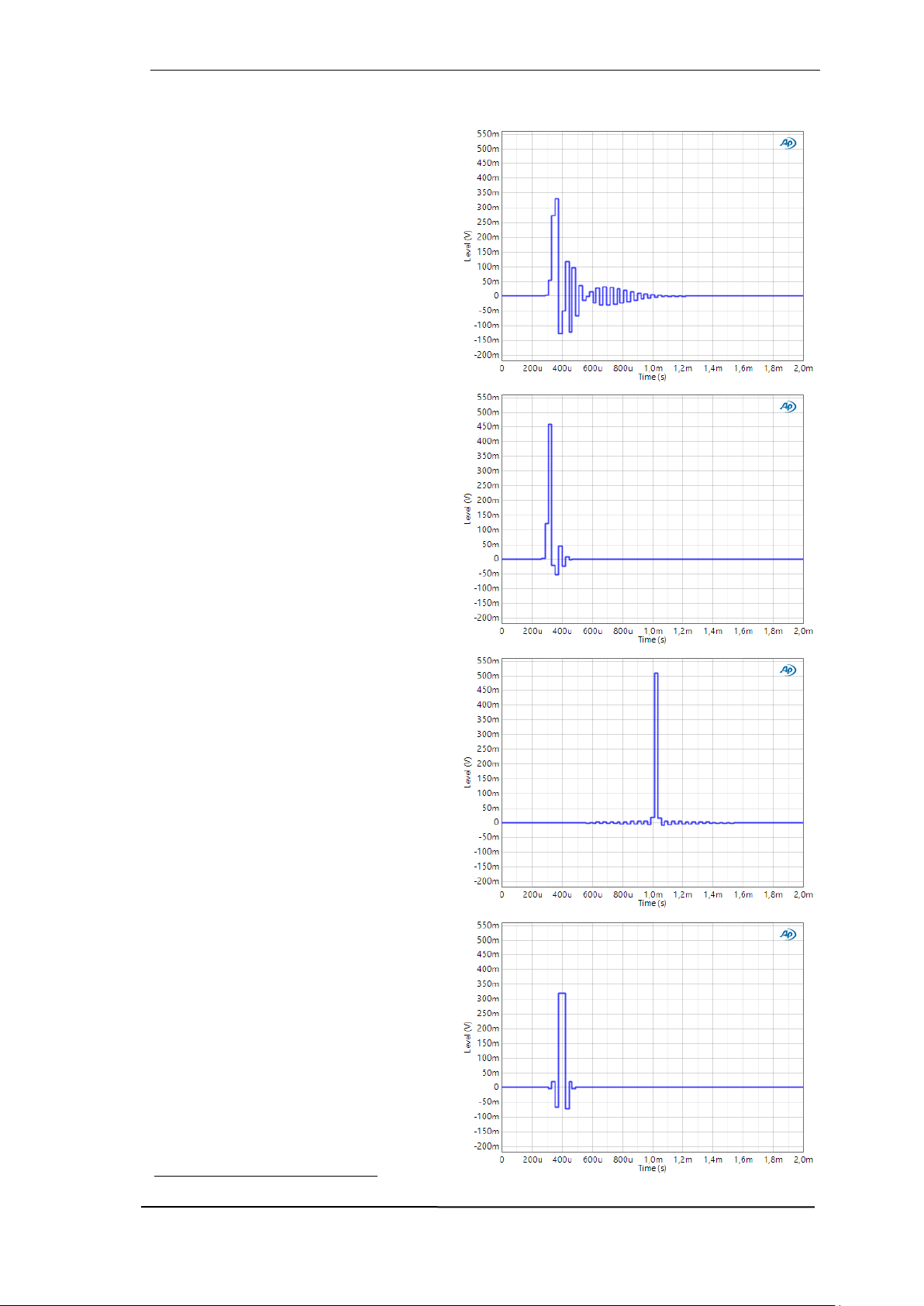
User’s Guide ADI-2/4 Pro SE – v 1.3
87
34.11 AD Impulse Responses
On the AD side the ADI-2/4 Pro SE offers
four oversampling filters, shown to the right
from top to bottom: Short Delay Sharp,
Short Delay Slow, Sharp and Slow. Basically these behave and operate exactly the
same way as the DAC filters described in
the next chapter. SD Sharp and Sharp offer
the most linear frequency response and
highest suppression of mirroring (aliasing)
at high frequency input signals. SD Slow
and Slow try to combine a high aliasing
suppression with an optimal impulse response, but start to act early within the
higher audible range at standard sample
rates. See measurements in chapter 34.13.
Note: SD Sharp/SD Slow each have nearly
the same frequency response as the
shown Sharp/Slow.
The pictures show the impulse response of
all four filters at 44.1 kHz. The source signal
is an analog single sample impulse (see
picture NOS in chapter 34.12), synced to
the sampling event. It includes frequencies
higher than half the sample rate that must
be removed from the aliasing filter of the
ADC. Therefore it is not possible to digitize
such a signal at 44.1 kHz sample rate without added rounding or pre/post ringing.
SD Sharp and SD Slow are IIR filters (also
called minimum phase), which are not
phase-linear and mostly cause post ringing. The advantage of IIR is the very low
latency of a few samples only, which is welcome in a studio monitoring situation.
Sharp and Slow are FIR filters that cause
post and pre-ringing. FIR in general has a
higher latency, but is phase-linear over the
whole frequency range. Slow shows a
lower amplitude - the filter's treble decrease
in the audible range, but only very low pre
and post ringing.
In Preamp mode the analog signal is AD-,
then DA-converted. In factory default state
this happens at 192 kHz sample rate. The
same impulse is recorded and played back
in much better quality, as the quadrupled
sample rate samples the 44.1 kHz single
sample impulse at least four times, and the
filters operate at a much higher frequency
as well. Therefore the pre- and post-ringing
is four times 'quicker', and as such only a
quarter in length. Still Slow offers the most
perfect impulse response.
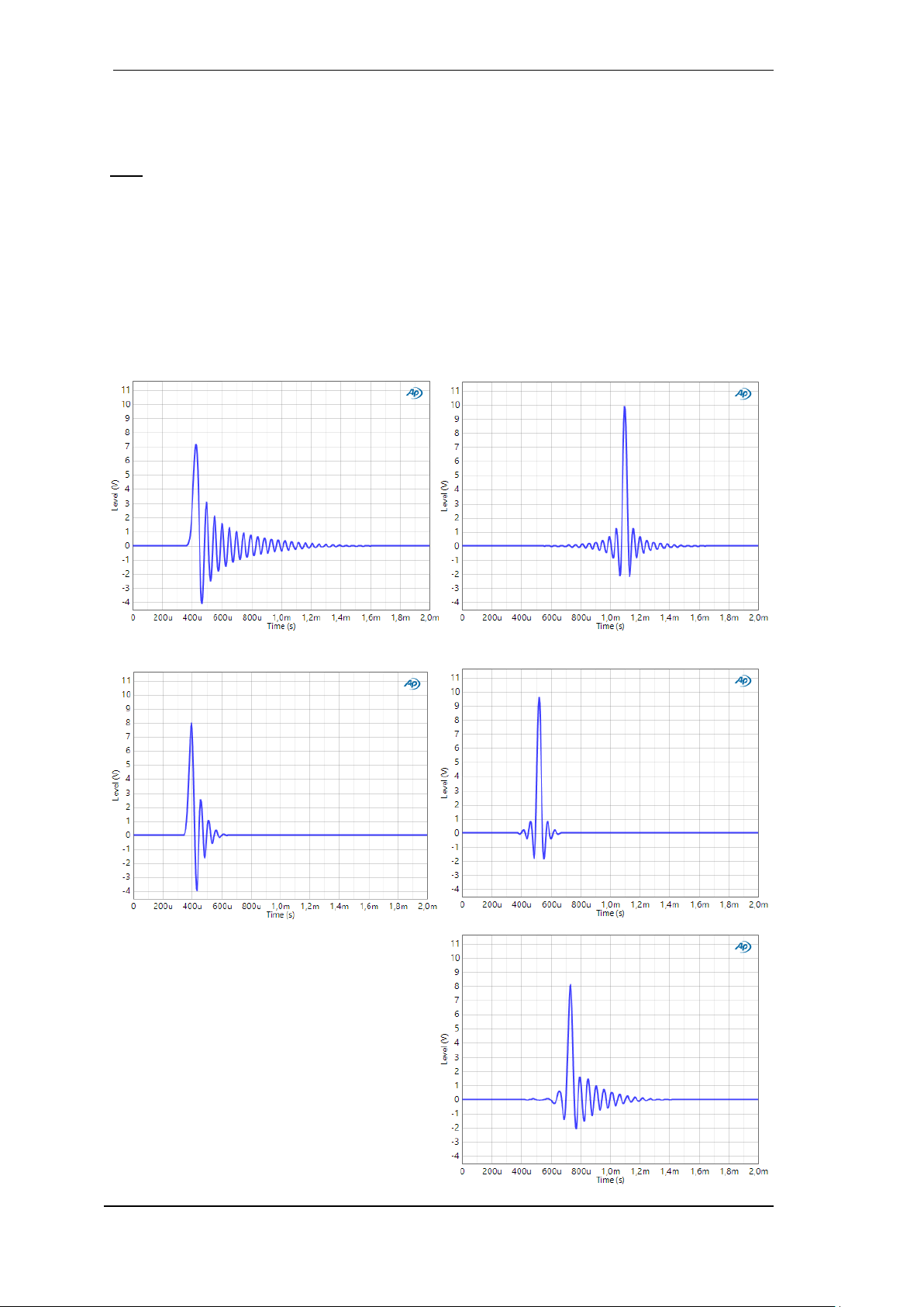
88
User’s Guide ADI-2/4 Pro SE - v 1.3
SD Slow and Slow work best at 88.2 and up, because the decrease in the high frequency area
then happens outside the audible range. At the same time the impulse response is near perfect
– caused by both the filter as well as the doubled sample rate.
Note: At 705.6 and 768 kHz sample rate the filter selection is not available. At these rates the
ADC uses an Linear Phase Slow Roll-Off filter. A different choice is not possible.
34.12 DA Impulse Responses
The screenshots show the analog output signal of the oversampling DAC filters, stimulated by a
digital single sample impulse at 44.1 kHz sample rate. While Slow has the most perfect response,
it loses around 2 dB already at 19 kHz, see chapter 34.15. Both Short Delay are IIR filters, the
other two are FIR type. FIR is phase linear over the whole frequency range.
Short delay Sharp Sharp
Short Delay Slow Slow
SD LD (Short Delay Low Dispersion)
The filter with the bulky name Short Delay Low
Dispersion attempts a compromise between
linearity, latency and preringing. The filter is
steep, but set comparatively low. It offers very
good stopband attenuation in return.

User’s Guide ADI-2/4 Pro SE – v 1.3
89
Brickwall
All the above filters intentionally violate a rule
of digital technology - at half the sample rate
the filter should already have maximum stop-
band attenuation, i.e. at 44.1 kHz sample rate
at an audio frequency of 22.05 kHz. But in
practice there are no disadvantages with a
slightly higher filter (24 kHz). However, the filter is further out of the audible range (good for
the ears), and easier to implement in hardware
(good for the chip manufacturers) - that's why
most filters are implemented this way. As an
alternative, the Sharp filter can also be selected with a matching stopband attenuation under the name Brickwall. The measurements
show that the filter is absolutely the same, but
starts a bit earlier, because the peak is slightly reduced in level. So the filter is not - as Brickwall
suggests - steeper, but simply shifted a bit downwards. See also chapter 34.15.
NOS (Non-Oversampling, SuperSlow)
The AKM DAC of the ADI-2 Pro includes another filter called Super Slow, whose impulse response looks perfect. But checking the output signal with an Oscilloscope reveals steps that are
more typical for so called Non-OverSampling (NOS) devices. That’s why this filter is called NOS
within the DAC filter menu.
Note that there is no audible distortion, the steps equal high frequency harmonics that are mostly
higher than 20 kHz. Please also note that Slow and especially NOS filters cause much more
aliasing into the audio band and out-of-band noise than Sharp filters.
Since the NOS filter is very popular in Hi-Fi and audiophile circles, but generally missing in ESS
DACs, RME has emulated the filter of the AKM DAC, and loads the appropriate filter coefficients
into the ESS chip in real time when NOS is selected. Miracle of technology...

90
User’s Guide ADI-2/4 Pro SE - v 1.3
34.13 Frequency Response Preamp Mode (AD/DA)
Note: 44.1 kHz to 384 kHz measured with filter SD Sharp on AD and DA.
34.14 AD Frequency Response and Filter Curves

User’s Guide ADI-2/4 Pro SE – v 1.3
91
34.15 DA Filter Curves @ 44.1 kHz
Note: Sharp/SD Sharp and Slow/SD Slow are very similar, but not fully identical. NOS shows a
very early drop. SD Low Dispersion shows a somewhat early treble drop, but also a very good
stopband attenuation, see next measurement.

92
User’s Guide ADI-2/4 Pro SE - v 1.3
34.16 Loudness
34.17 Bass / Treble

User’s Guide ADI-2/4 Pro SE – v 1.3
93
34.18 Distortion Measurements Analog I/O
The following measurements show spectral analysis of the AD and DA conversion of the ADI-2/4
Pro SE, which includes the analog input and output stages. While the noise and modulation behavior is identical for all devices, the AD and DA chips used have tolerances in the height and
distribution of the harmonics. The distortion shown here is slightly different for each device, and
can be a few dB lower or higher.
Inputs XLR / TRS
Outputs XLR and rear TRS

94
User’s Guide ADI-2/4 Pro SE - v 1.3
Output Phones TRS
+20 dBu output level @ 32 Ohm equal 1.9 W (per channel)
34.19 Crosstalk Phones Balanced / Unbalanced
From top to bottom (all 32 Ohm load): TRS extension cord 3 meter (9.8 ft). TRS Phones Out 1/2
and 3/4. Phones Balanced mode using 2 x TRS Out or Pentaconn. No load: XLR Out 1/2.

User’s Guide ADI-2/4 Pro SE – v 1.3
95
34.20 Extreme Power Charts
Note: Since the maximum undistorted output level is reached at VOLUME +2.5 dB, the Hi-Power
measurements (unbalanced and balanced) were taken at this setting. Low Power and IEM were
measured at VOLUME 0 dB.

96
User’s Guide ADI-2/4 Pro SE - v 1.3
34.21 Phones Distortion Comparison
The Extreme Power output stage remains virtually distortion-free under load until the maximum
level is reached (clipping), which leads to an increasingly lower THD+N as the level increases.
This is not the case with many other headphone amplifiers.
So much for our marketing department. In the following chapter, we will show how that looks like
in reality – precisely measured.
34.22 Measurements Distortion vs Output Power under Load
Measured with Audio Precision APx555B and the Neurochrome HP-Load. Maximum output
power is in Lo-Power and IEM mode with VOLUME set to +2.5 dB. IEM Balanced equals LoPower unbalanced.

User’s Guide ADI-2/4 Pro SE – v 1.3
97

98
User’s Guide ADI-2/4 Pro SE - v 1.3
34.23 Impedance based Level Meters PH 1-4
The horizontal level meters in various screens of outputs 1 to 4 show the digital level fed to the
DAC. With loads higher than 32 Ohms the level meter's display matches the real analog output
level (0 dBFS = +19 dBu). But at 20 Ohms the ADI-2/4 Pro SE delivers only +18 dBu, at 16 Ohms
+16.5 dBu to the phones outputs, because a reasonable current limiting circuit prevents a too
high output power at lower load impedances. In Hi-Power mode, the highest undistorted value at
16 Ohms is -2.5 dB on the level meter. Consequently it should either change its colour to red
then, or rescale the highest level to -2.5. Only then the user would be clearly informed which
maximum level can be issued by the device undistorted.
The reaction of the current limiter in the Extreme Power output stages can be used to realize a simplified impedance detection. Which can then be used to re-scale the level meters.
Exactly that happens fully automated within the ADI-2/4 Pro
SE. The peak values to the right serve as pre DAC information and stay unchanged, but the meter's yellow and red
areas get shifted and extended to the left.
With revised volume settings, where the level meter stays below the red area, the user can now
be 100% sure that the ADI-2/4 Pro SE operates absolutely free of distortion, even in the most
extreme applications.
Notes on functionality: The re-scaling happens not before the highest undistorted level is exceeded. The re-scaling stays visible until the phones plug has been removed. An ongoing overload situation causes the activation of the Overload warning screen and a disconnection of the
phones output.

User’s Guide ADI-2/4 Pro SE – v 1.3
99
34.24 Digital Volume Control
The ADI-2/4 Pro SE deliberately avoids an analog level adjustment by means of a potentiometer.
Its digital level control in TotalMix technology surpasses an analog one in practically every conceivable point. Typical disadvantages of setting with potentiometers:
Synchronicity errors lead to panoramic shifts and significant volume deviations left / right, in
particular near the end points of the adjustment range.
In the middle setting range, there is an increased crosstalk and changes in the frequency
response. Changes in the frequency response also occur at the end regions of the adjustment
path.
The setting range for optimum volume adjustment is often too small, or at the lower or upper
end of the potentiometer's adjustment range.
Non-reproducible settings (except 0 and 11).
Higher THD/THD+N. A point well known to measurement technicians. As soon as an analog
potentiometer is in the signal path, the unstable contact between wiper and resistive track
causes noise, which contains both THD (distortion) and N (noise), even in the stationary state.
Thus the -110 dB of a DAC quickly gets reduced to for example -80 or -70 dB.
Special volume ICs, which activate different resistance values by means of numerous electronic
switches, avoid some of the above mentioned points. Unfortunately, even the best of these ICs
do not achieve either THD or dynamics of the DACs used in the ADI-2/4 Pro SE, thus would affect
its analog output signal.
However, none of this is an issue with RME's digital volume control!
In fact an analog volume control has a (theoretical) advantage in only one point, namely the maximum signal to noise ratio at a higher level reduction. In reality, current circuitry overturns the
theory, and the SNR at the output of such a device is no better than that of a digitally controlled
one. This is even more true the better the DA converter works and the less noise it has - just like
the ADI-2/4 Pro SE, which provides the maximum noise ratio over a wide level range of 20 dB,
thanks to its four reference levels realized in the analog domain.
The most often cited issue of a digital volume control is an alleged loss of resolution at higher
attenuation. An example: 117 dB dynamic roughly equals 19 bit resolution. A volume attenuation
of 48 dB (8 bit) leaves 11 bit of resolution. Such a simple, but important details omitting argumentation, usually ends with: the music must sound distorted in quieter parts, and the signal to noise
ratio is down to a useless 69 dB.
The former is simply wrong, the latter irrelevant in practice. Indeed there is a reduced signal to
noise ratio, but it doesn't matter, as the noise was not audible before (below the hearing threshold), and is still not audible after lowering the level. And the reduced SNR also applies to devices
with potentiometers, since the potentiometer is never placed at the output, but in the middle of
the circuit, followed by further electronics which also add some basic noise.
The quality of the ADI-2/4 Pro SE's digital volume control is best shown by measurements. Hard
times coming up for convinced supporters of the analog control, because here it is very clear that
the disadvantages of a digital volume adjustment, such as roughness and distortions at higher
attenuation, simply do not exist - at least with RME.

100
User’s Guide ADI-2/4 Pro SE - v 1.3
The following measurement shows a digital full-scale sine of 1 kHz, 16 bits without dither, which
is reduced in level by 40 dB. Also shown are a full-scale sine of 1 kHz with 24 bit, at 60 dB and
93.8 dB level attenuation, which is the lowest volume setting the ADI-2/4 Pro SE offers.
A high-resolution FFT makes it possible to disassemble the signal into individual frequencies, and
to identify unwanted components down to a level of -190 dBFS. The measurement shows that
the undithered 16 bit signal does not produce any distortion or other tones above -170 dBFS. So
at a volume setting of -40 dB the measurable THD is -130 dB. At 24 bit a volume setting of -60
dB also achieves -130 dB without distortion. And at a volume setting of -93.8 dB there are still 93 dB THD measurable.
These results clearly show that distortion products of the digital volume control are not drowned
by the DAC's noise, but are not generated at all. It works perfectly even with an undithered 16 bit
signal, no detectable distortion products are produced.
If the volume control is measured at the analog output, the demonstrable THD is reduced to
around -100 dB at a volume setting of -60 dB, by the self-noise of the DAC (SNR 120 dB RMS
unweighted). In the above measurement that would be seen as straight noise floor at -160 dBFS.
The digital volume control of the ADI-2/4 Pro SE therefore works much more precisely and cleaner
than required for current top-level DACs.
In summary:
RME's digital volume control in 42 bit TotalMix technology avoids all the disadvantages of analog
level control via pots, is easy to use, offers reproducible settings, and the highest sound quality.
 Loading...