

Page 1
32 Bit / 768 kHz
Hi-Res Audio
SteadyClock
2 Channels Analog / Digital Converter
4 Channels Digital / Analog Converter
2 Extreme Power Headphone Outputs
User’s Guide
ADI-2 Pro
Conversion done right
™
III
AES / ADAT / SPDIF Interface
32 Bit / 768 kHz Digital Audio
USB 2.0 Class Compliant
Digital Signal Processing
Advanced Feature Set
SyncCheck
™
Page 2

General
1 Introduction ...............................................................5
2 Package Contents .....................................................5
3 System Requirements ..............................................5
4 Brief Description and Characteristics.....................6
5 First Usage - Quick Start
5.1 Connectors and Controls ........................................7
5.2 Quick Start ..............................................................8
5.3 Operation at the unit................................................8
5.4 Overview Menu Structure .......................................9
5.5 Playback................................................................10
5.6 Analog Recording..................................................10
5.7 Digital Recording...................................................10
6 Power Supply...........................................................11
7 Firmware Update .....................................................11
8 Features Explained
8.1 Extreme Power Headphones Outputs ..................12
8.2 Dual Phones Outputs............................................13
8.3 5-band Parametric EQ ..........................................13
8.4 Bass / Treble .........................................................14
8.5 Loudness...............................................................14
8.6 SRC (Sample Rate Conversion) ...........................15
8.7 Crossfeed..............................................................15
8.8 DSP Limitations.....................................................16
Basic and Stand-Alone Operation Details
9 Operation and Usage ..............................................18
10 Front Panel Controls
10.1 Keys .....................................................................18
10.2 Encoders ..............................................................18
11 VOL ...........................................................................19
12 I/O
12.1 Analog Input
12.1.1 Settings ........................................................19
12.1.2 Parametric EQ..............................................20
12.2 Main Output 1/2
12.2.1 Settings ........................................................21
12.2.2 Bass/Treble ..................................................22
12.2.3 Loudness......................................................23
12.3 Phones Output 3/4 ...............................................23
13 EQ .............................................................................24
14 SETUP
14.1 Options
14.1.1 Hardware/Diagnosis.....................................26
14.1.2 Clock ............................................................27
14.1.3 Device Mode ................................................27
14.2 Load/Store all Settings .........................................28
15 Meter Screens
15.1 Global Level Meter ...............................................29
15.2 Analyzer ...............................................................29
15.3 State Overview .....................................................30
15.4 Dark Volume ........................................................31
16 Warning Messages..................................................31
2
User’s Guide ADI-2 Pro - v 1.91
Page 3

17 Modes
17.1 Auto...................................................................... 33
17.2 Preamp ................................................................ 34
17.3 AD/DA Converter .................................................35
17.4 USB...................................................................... 36
17.5 Digital Through..................................................... 38
17.6 DAC ..................................................................... 39
18 Balanced Phones Mode.......................................... 40
19 DSD Operation
19.1 General ................................................................41
19.2 Direct DSD ........................................................... 41
19.3 DSD Playback...................................................... 42
19.4 DSD Record ......................................................... 42
19.5 DSD Level Meter.................................................. 43
19.6 Beyond… .............................................................43
Inputs and Outputs
20 Analog Inputs .......................................................... 46
21 Analog Outputs
21.1 General ................................................................46
21.2 Line Out TS 1/2.................................................... 47
21.3 Line Out XLR 1/2 ................................................. 47
21.4 PH Out 1/2 ...........................................................47
21.5 PH Out 3/4 ...........................................................48
22 Digital Connections
22.1 AES...................................................................... 48
22.2 SPDIF ..................................................................49
22.3 ADAT ...................................................................50
Installation and Operation - Windows
23 Driver Installation.................................................... 52
24 Configuring the ADI-2 Pro
24.1 Settings Dialog..................................................... 53
24.2 Clock Modes - Synchronization ........................... 54
25 Operation and Usage
25.1 Playback .............................................................. 54
25.2 DVD Playback (AC-3 / DTS)................................ 55
25.3 Multi-client Operation ........................................... 55
25.4 Multi-interface Operation ..................................... 55
25.5 ASIO .................................................................... 56
26 DIGICheck Windows ............................................... 56
Installation and Operation – Mac OS X
27 General..................................................................... 58
27.1 Configuring the ADI-2 Pro.................................... 58
27.2 Clock Modes - Synchronization ........................... 59
27.3 Multi-interface Operation ..................................... 59
28 DIGICheck Mac........................................................ 59
User’s Guide ADI-2 Pro – v 1.91
3
Page 4

Installation and Operation – iOS
29 General .....................................................................62
30 System Requirements ............................................62
31 Setup ........................................................................62
32 Supported Inputs and Outputs ..............................62
Technical Reference
33 Technical Specifications
33.1 Analog Inputs .......................................................64
33.2 Analog Outputs ....................................................64
33.3 Digital Inputs ........................................................65
33.4 Digital Outputs......................................................66
33.5 Digital ...................................................................66
33.6 General ................................................................66
33.7 Connector Pinouts................................................67
34 Technical Background
34.1 Lock and SyncCheck ...........................................68
34.2 Latency and Monitoring........................................69
34.3 Balanced Phones Mode .......................................70
34.4 Emphasis .............................................................72
34.5 Noise Level in Hi-Speed Modes...........................73
34.6 SteadyClock .........................................................74
34.7 AD Filter Curves ...................................................76
34.8 DA Filter Curves 44.1 kHz ...................................76
34.9 DA Impulse Responses .......................................77
34.10 AD Impulse Responses .......................................78
34.11 Frequency Response Measurements..................79
34.12 Loudness..............................................................79
34.13 Total Harmonic Distortion Measurements ...........80
34.14 Extreme Power Charts.........................................81
34.15 Phones Distortion Comparison ............................82
34.16 Impedance based Level Meters PH 1-4 ..............82
34.17 USB Audio (Windows) .........................................83
34.18 ADI-2 Pro as Hardware I/O for Measurements....84
34.19 Operation in the Hi-Fi Environment......................86
34.20 Digital Volume Control .........................................89
34.21 Bit Test .................................................................91
Miscellaneous
35 Accessories .............................................................94
36 Warranty...................................................................94
37 Appendix ..................................................................95
38 Declaration of Conformity ......................................96
4
User’s Guide ADI-2 Pro - v 1.91
Page 5

1. Introduction
RME’s ADI-2 Pro is a true milestone in many ways. Looking at the multitude of AD/DA converters, USB DACs and dedicated headphone amps available, RME developers felt they all lacked
obvious features that are unavoidable to enjoy operation as well as when listening to music.
And while many of those devices claim to use the latest state-of–the–art whatsoever converter
chip, serious magazines and RME staff were repeatedly disappointed to find that in the end the
stellar technical data published in ads and datasheets were nowhere to be found.
With the ever growing popularity of headphones and latest AD/DA chips pushing technical data
further, the time was right for a new RME gem. A unit with the industry’s biggest footprint per
feature ratio, with specs that are as real as RME‘s reputation, a feature set that is unheard of,
useful features that for unknown reasons no one else implemented, and two extremely powerful
headphone outputs, that will be your new reference in accuracy and dynamic range.
Here it is – the ADI-2 Pro, the little wonder, a host of devices all put together into one unit, with
a simple and mostly automated way of using it right out of the box:
x A high-end AD/DA converter in professional studio quality
x A double headphone amplifier in true high-end quality
x A USB DAC like no other - the most versatile and capable one around
x A high-end AD/DA frontend and headphone amp for iPad and iPhone
x An AD/DA frontend for measurement systems at up to 768 kHz sample rate
x A multi-format converter (AES, SPDIF, ADAT) with monitoring
x An SPDIF/ADAT playback system
x A DSD record and playback solution
All there is left to say now is: Enjoy!
2. Package Contents
x ADI-2 Pro
x Manual
x External switched power supply, lockable connector, DC 12 V 24 W
x Power cord
x Digital breakout cable AES/SPDIF (BO968)
x Quick start guide
3. System Requirements
General:
x Power supply 12V DC, 1.5 A or up
For computer based operation:
x Windows 7 or up, Intel Mac OS X (10.6 or up)
x 1 USB 2.0 port or USB 3 port
x Computer with at least Intel Core i3 CPU
For iOS based operation:
x iPhone or iPad with iOS 7 or up
x Dock or Lightning to USB adapter
User’s Guide ADI-2 Pro – v 1.91
5
Page 6

4. Brief Description and Characteristics
The ADI-2 Pro is a 2-channel analog input to digital and 4-channel digital to analog output converter in a half-rack (9.5") enclosure of 1 U height. Latest 32 bit / 768 kHz converters offer up to
124 dBA signal to noise ratio. This value is not only printed in the brochure – it is what the unit
achieves in real-world operation.
Reference class tech specs throughout are combined with an unprecedented feature set. A
powerful DSP adds all kinds of useful audio processing, including 5-band parametric EQ, fast
Bass/Treble adjustment, Crossfeed, and a new concept in Loudness sound control.
Operation is quick and easy through 3 encoders with push button function and 4 more buttons
to access dedicated menus. The unit remembers all current settings, even the menu position.
Additionally the unit’s whole setup as well as equalizer settings can be stored under individual
names.
A high resolution IPS panel for the graphical operation surface eases operation even more, and
displays further functions provided by the DSP, namely Peak level meters, a 30-band analyzer
in DIGICheck biquad filter technology, and a State Overview screen listing the current states of
SPDIF, AES, USB and clock.
The digital inputs SPDIF coaxial (or optical) and AES operate simultaneously. An additional
Sample Rate Converter decouples the SPDIF or AES clock for even simpler setups, and also
supports up- and down-sampling of the input signals. SPDIF optical also supports 2 channels of
ADAT operation, at up to 192 kHz.
When used as USB interface, the Class Compliant UAC 2 mode can be set to Stereo or Multichannel. Multi-channel mode turns the ADI-2 Pro into a 6 channel (Analog 1/2, AES, SPDIF)
record and 8 channel (Analog 1/2/3/4, AES, SPDIF) playback audio interface, that even works
as iPad front-end up at up to 192 kHz sample rate. In stereo mode sample rates up to 768 kHz
are supported, for high resolution recordings or PCM, DXD and DSD record/playback.
The servo balanced analog inputs and dedicated balanced and unbalanced outputs are fitted
with both XLR and 1/4" TRS/TS jacks. The unit uses a fully balanced and DC-coupled circuit
design, for highest phase accuracy at lowest roll-off. The only capacitors in the whole signal
path, non-polar MUSE audio capacitors from Nichicon, reside directly at the input of the unit
(DC protection).
The two Extreme Power headphone outputs provide reference sound and headroom. RME’s
Advanced Balanced mode not only adds balanced phones operation to the feature list, but also
premiers a new concept on improving the balanced mode even further.
To maintain the full dynamic range within the best operating level, discrete 4-stage reference
level settings were realized for maximum dynamic range (+4, +13, +19, +24 dBu). Also available are 0 to +6 dB digital trim for fine input sensitivity adjustment in steps of 0.5 dB.
The ADI-2 Pro supports all sample rates between 32 kHz and 768 kHz. Furthermore, RME's
SteadyClock III guarantees exceptional performance in all clock modes. Thanks to a highly
efficient jitter suppression, the AD- and DA-conversion always operates on highest sonic level,
being completely independent from the quality of the incoming clock signal.
The ADI-2 Pro shines in both studio and home usage. Its click- and noise-free on/off operation
and a comfortable, illuminated standby button add to the soft, modern desktop design.
Mobile and galvanically separated usage is possible through a 12V connector for easy battery
connection.
6
User’s Guide ADI-2 Pro - v 1.91
Page 7

5. First Usage – Quick Start
5.1 Connectors and Controls
The front of the ADI-2 Pro has 3 hi-precision rotary encoders with push function, 4 buttons, a
standby power button, a high resolution IPS display, and two TRS headphone outputs.
The output channels 1/2 and 3/4 feed two phones outputs via two independent Extreme Power
driver circuits, optimized for both high and low impedance headphones. Their unbalanced output signal is of highest quality. With 120 dBA SNR there is no audible hum and noise at those
outputs.
In case a phones output is to be used as line output, an adapter TRS plug to RCA phono plugs,
or TRS plug to two TS plugs is required.
The rear of the ADI-2 Pro has 2 servo-balanced analog inputs on combo XLR/TRS sockets, 2
TS sockets as unbalanced outputs, 2 XLR sockets as balanced outputs, TOSLINK optical I/O, a
USB socket, and a lockable power socket. An included breakout cable is connected to the DB-9
socket and provides AES I/O via XLR and SPDIF coaxial I/O via RCA.
The ADI-2 Pro has two analog line inputs that can operate with levels up to +24 dBu. The electronic input stage uses a servo balanced design which handles unbalanced and balanced signals correctly, automatically adjusting the level reference.
When using unbalanced cables with the XLR inputs, pin 3 of the XLR jack should be connected to ground. Otherwise noise may occur, caused by the unconnected negative input of
!
the balanced input.
The analog inputs 1/2 include 6 dB digital gain control via DSP, and a choice of +4 dBu, +13
dBu, +19 dBu or +24 dBu as reference level, performed in the analog domain.
The short circuit protected, low impedance XLR line outputs do not operate servo balanced! When connecting unbalanced equipment via XLR, make sure pin 3 of the XLR
output is not connected. A connection to ground might cause a decreased THD (higher
!
distortion) and increased power consumption!
Optical I/O (TOSLINK): The unit automatically detects SPDIF or ADAT input signals. The optical output can operate as ADAT or SPDIF output, depending on the current setting in the Setup
menu (Options, Hardware/Diagnostics). Note that only channels 1/2 from the ADAT stream can
be accessed. SMUX and SMUX4 (up to 192 kHz) are still supported.
USB 2.0: Standard USB socket for connection to the computer. The ADI-2 Pro operates as
Class Compliant device, in either 2-channel or 8-channel mode (configured in Setup). It can be
directly used with Mac OS X and iOS (iPad, iPhone). For Windows the RME MADIface series
driver adds WDM and ASIO.
Socket for power connection. This socket supports locking type jacks as found on the included
RME DC power supply. After inserting the connector carefully turn it by 90° so that it locks.
User’s Guide ADI-2 Pro – v 1.91
7
Page 8
5.2 Quick Start
Connect the unit to the included power supply and push the Standby button to start. The ADI-2
Pro ships with Basic Mode Auto activated (SETUP – Options – Device Mode – Basic Mode).
The input selection for SPDIF (coaxial or optical), and the source selection for Phones Out 3/4
are also set to Auto, the SRC is activated for the SPDIF input. With Auto active the unit will turn
into different modes depending on connected cables:
x Preamp: Analog in to Analog out (internal digital out to in). This mode is active when no digi-
tal input signal and no USB is detected.
x AD/DA: Converter Mode, analog in to all digital outs, digital in to all analog outs. This mode
becomes active as soon as a digital signal is attached. This signal will also become the signal source. In case more than one digital signal is found the user has to manually select the
source to be monitored. The SRC is active as default and assigned to SPDIF. Clock mode is
slave to AES in, but will adapt to the detected source (Auto).
x USB: or interface mode (also USB DAC). If USB is detected all inputs are routed to USB, all
outputs are fed from USB. USB has priority over the converter mode. In Setup the unit can
be configured as 2- or 8-channel device. In most cases 2-channel will be the better choice.
USB can be manually overridden by selecting a different mode. This will change the I/O routing,
but not disable USB itself. All inputs are still available via USB, outputs 3/4 can playback USB.
In all modes except Basic Mode DAC output PH 3/4 is freely configurable, any possible source
can be monitored independently from Outputs 1/2.
The unit remembers all settings, and loads these automatically when it is switched on again. To
switch off, press the Standby button for at least 0.5 seconds.
5.3. Operation at the Unit
Useful information for a smooth start:
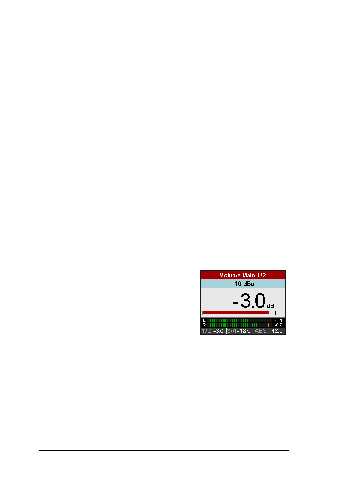
Turning the big VOLUME knob brings up the Volume
screen of the currently selected output. Pushing the big
Volume knob changes the volume setting between Outputs
1/2 and 3/4. The status bar at the bottom of the display
shows the current dB value of both volume settings. A white
rectangle around it (marker) indicates which volume the big
encoder is currently set to control.
The header shows the currently selected output as well as
hardware reference level (Ref Lev, see chapter 12.2.1).
The EQ is set up either directly within the I/O menu structure (key I/O, turn encoder 2 to access
Settings, Parametric EQ, Bass/Treble and Loudness), or via the graphical EQ screen which is
shown after pressing the EQ key. In this screen the cursor has three positions: top*, the EQ
parameter line below the response curve, and filter selection type for band 1 and 5 (Peak, Shelf,
Low/High Cut). The cursor is moved up or down by pushing encoder 1 or 2. When in the EQ
parameter line, all values are no longer grayed out. In this state the big encoder steers Gain,
encoder 1 Frequency, and encoder 2 Quality factor. This way the EQ is extremely fast set up
and edited.
The graph has 5 different colors matching the 5 bands that can be adjusted. If the line is just
grey the EQ is disabled (bypass). The EQ can be enabled in the second menu which comes up
by pushing the EQ key a second time.
*(shown by a 1 beside the current channel. Turning encoder 1 will change to the EQ settings of the other channels)
8
User’s Guide ADI-2 Pro - v 1.91
Page 9
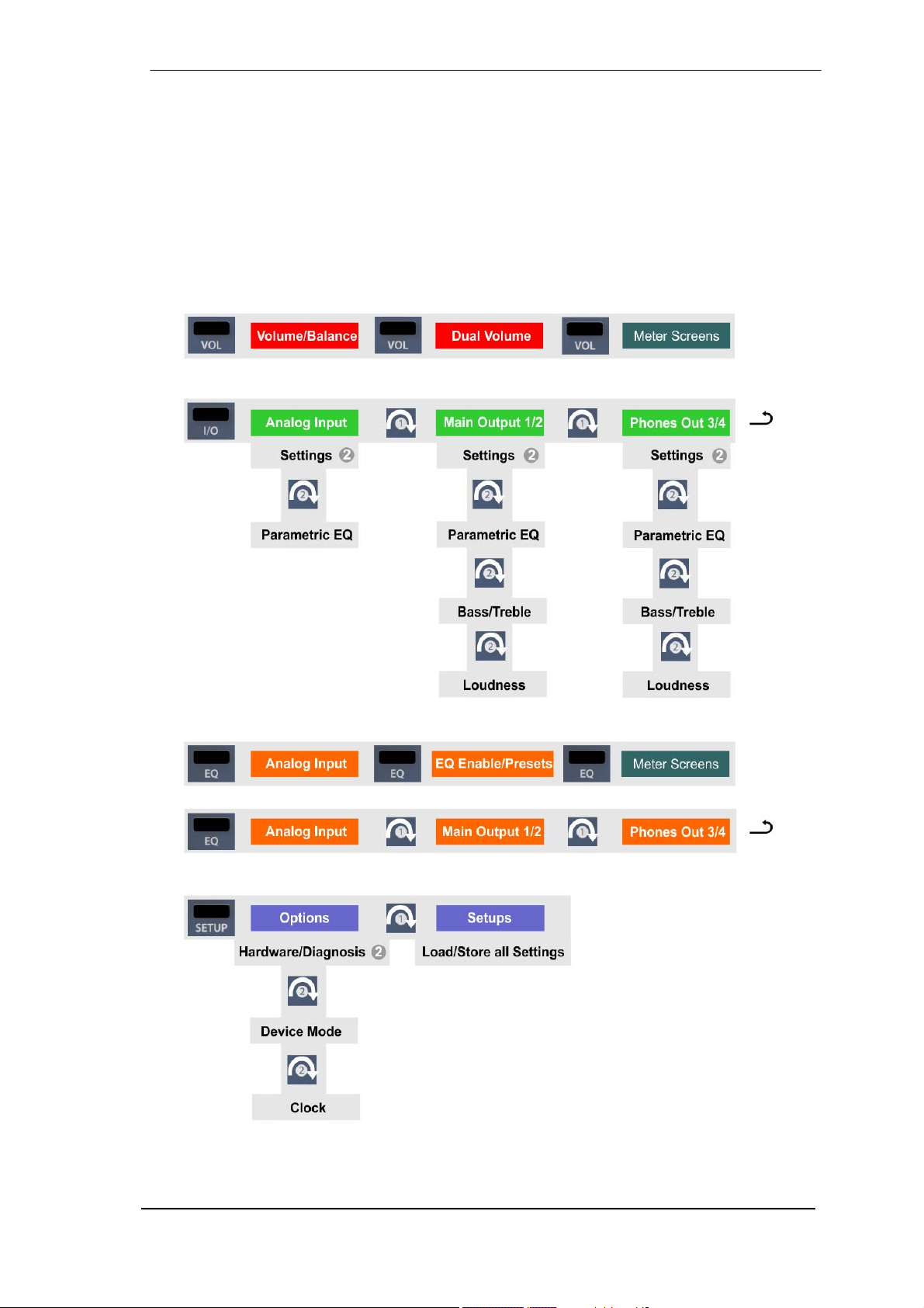
The unit has several informative screens on the top level. These are Global Level Meters,
Analyzer Input, Analyzer Output 1/2, Analyzer Output 3/4, State Overview and Dark Vol-
ume. Change between them by pushing encoder 1 or 2 whenever any of them is displayed. To
quickly call them up simply press any of the 4 buttons several times.
In all these screens turning encoder 1 and 2 brings up the quick access to Bass and Treble,
with ± 6 dB maximum boost/cut.
5.4. Overview Menu Structure
User’s Guide ADI-2 Pro – v 1.91
9
Page 10

5.5 Playback
In the audio application being used, the ADI-2 Pro must be selected as output device. It can
often be found in the Options, Preferences or Settings menus, as Playback Device, Audio De-
vices, Audio etc. After selecting a device, audio data is sent to an analog or digital port, depend-
ing on which has been selected as playback device.
Increasing the number and/or size of audio buffers may prevent the audio signal from breaking
up, but also increases latency i.e. output is delayed.
5.6 Analog Recording
For recordings via the analog inputs the corresponding record device has to be chosen.
Channels 1/2 of the ADI-2 Pro have digitally controlled gain and four hardware-based reference
levels. The digitally controlled gain offers a gain setting in steps of 0.5 dB within a range of 0 dB
to +6 dB, for fine-tuning the input sensitivity. The four hardware-based Reference Levels allow a
coarse adaption to the current source signal. The ADI-2 Pro has global as well as channel level
meters. Setting the correct Ref Level to avoid clipping/overload is easy to do.
The combo XLR/TRS sockets are designed for line signals. Sources that require higher input
impedances, like guitars, need an additional impedance buffer in front of the ADI-2 Pro.
5.7 Digital Recording
The easiest way to perform digital recordings with the ADI-2 Pro is to set the SRC to the currently used input (SPDIF or AES), then set the Clock to INT(ernal) and the desired sample rate
– then start recording.
The SRC serves as clock decoupler. When not using the SRC, the ADI-2 Pro must be in total
Sync to the external digital device, as either master or slave. Taking this into account, RME
added a comprehensive I/O signal status display to the ADI-2 Pro, showing sample frequency,
lock and sync status in the State Overview screen and the bottom status bar.
The sample frequency shown in the State Overview screen is useful as a quick display of the
current configuration of the unit and the connected external equipment. If no sample frequency
is recognized, it will show - - (No Lock).
This way, configuring any suitable audio application for digital recording is simple. After connecting it the ADI-2 Pro displays the internal and external sample rate. This parameter can then
be changed in the application’s audio attributes (or similar) dialog.
10
User’s Guide ADI-2 Pro - v 1.91
Page 11
6. Power Supply
In order to make operating the ADI-2 Pro as flexible as possible, the unit has a universal DC
input socket, accepting voltages from 9.5 Volts up to 15 Volts. An internal switching regulator of
the latest technology with high efficiency (> 90%) prevents internal hum noise by operating
above audible frequencies. Internally the switching regulator is followed by standard linear regulators, followed by super low-noise linear regulators. Therefore the ADI-2 Pro achieves its technical specs even with less optimal power supplies. Or in other words: the choice of power supply is not critical.
Still the unit includes a high-quality switching power supply, 12 V / 2 A, which not only accepts
any mains voltage between 100 V and 240 V (usable world-wide), but is also fully regulated
against voltage fluctuations and suppresses line noise. Additionally it only weights 150 g in spite
of its high power of 24 Watts.
The DC input of the ADI-2 Pro also allows for the use of a rechargeable lead-battery or LiPo
instead of a power supply, for completely independent mobile operation and ground isolation. A
matching connection cable (power jack to terminals 6.3 mm) is available from RME. Special
power banks in the range of 10,000 mAh and up can be found equipped with a 12 V output.
These offer a perfect solution for mobility as well as ground isolated operation, for small money.
7. Firmware Update
The ADI-2 Pro might receive improved features or bug fixes by a firmware update. This update
will be available from the RME website, section Downloads, USB. Download the tool that
matches your operating system (Mac or Windows), then unpack the zipped archive.
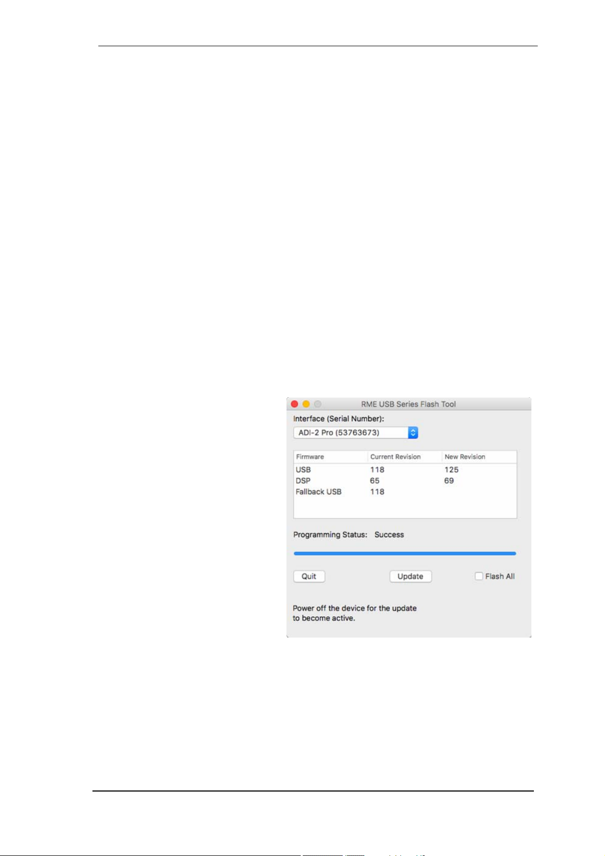
The Flash Update Tool updates the
firmware of the ADI-2 Pro to the latest
version. Under Windows it requires an
already installed MADIface series
driver, which is found on the same
download page.
Start the Flash Update Tool. It displays
the current revision of the ADI-2 Pro
firmware, and whether it needs an
update or not. If so, then simply press
the 'Update' button. A progress bar will
indicate when the flash process is
finished (Verify Ok).
After the update the ADI-2 Pro needs
to be reset. Push the standby button to
switch it off for 5 seconds.
When the update unexpectedly fails
(status: failure), the unit's Safety BIOS
will be used from the next boot on, the
unit stays fully functional. The flash process should then be tried again.
The flash process does not affect user data like sample rate choices, EQ settings or Setups.
Returning to Factory State
In case a total reset is desired: hold encoder 1 and the VOL button pushed while turning on the
unit. This will reset all memory to factory default. Setups and EQ Presets stored by the user will
not be deleted.
User’s Guide ADI-2 Pro – v 1.91
11
Page 12

8. Features Explained
8.1 Extreme Power Headphone Outputs
During the development of the ADI-2 Pro an extensive research on today’s headphone amp
technology as well as headphones has been carried out. Many (many!) headphones later a
maximum output level of +22 dBu (10 Volt) was set as development goal, as it will drive even
insensitive headphones sufficiently, while a maximum output current of around 260 mA per
channel will result in lots of power for lower impedance phones (1.5 Watts @ 32 Ohm).
Limiting the current makes a lot of sense. It is needed to control the internal power supply, to
not fully overdrive (and destroy) weaker headphones, and prevents malfunction at short-circuit
state. The Extreme Power output stage acts like a small power amplifier, so it got a similar feature set: a relay that mutes and interrupts the connection to the phones, a DC sensing circuit to
prevent DC at the output (DC destroys your precious phones already when the rated watts are
not even closely reached!), and an over-current protection circuit that will notice when a shortcircuit causes too high current, preventing the output stage to get destroyed. In light of the malicious treatment of this output stage during development it needs to be mentioned that it can not
be destroyed by a short-circuit at the output nor by overheating. Still some extra safety won’t
hurt, and the over-current protection circuit got in.
A goal during development was to build a headphone amp that not only reaches very low THD
un-loaded (the typical way of measuring it), but very low THD values with a 32 or 16 ohm realworld load. This was achieved in the new Extreme Power headphone driver output stage. It
uses 6-fold spread power technology, improved thermal conductivity and a special super-low
distortion driver design. The result is THD below -110 dB at 32 Ohm load even near full output
level (clipping), the same SNR as the DAC provides (120 dBA), an output impedance of only
0.1 Ohms, totally stable operation, and a frequency response from 0 Hz up to 80 kHz, with just
0.5 dB decrease at the top end. The result: No audible hum, noise or distortion, fully transparent
and crystal clear sound at any volume setting, for any personal taste in any application.
And there is more. The headphone sockets of the ADI-2 Pro have sensor contacts. The unit
always knows when a headphone jack is inserted or removed. The DSP uses this information
for several superior, partly never-seen before features. For example when inserting the headphone jack into Ph 3/4, the ADI-2 Pro activates the mute relay after half a second, then the DSP
ramps up the volume slowly from lower level to the last used state. Comfortable? Luxurious?
Yes, but the main reason for it was to give the user a chance to react. Extreme Power headphone outputs set to full output level, music already playing at full level, inserting the phones,
and the moment the relay switches on the doctor is called, diagnosing sudden deafness - this
should and can not happen with the ADI-2 Pro. When the volume is ramped up one has the
time to either quickly set the phones off, unplug the phones again, or to grab the Volume knob
to quickly turn it down.
To guarantee that the Volume knob will be set to control the correct outputs in that moment, the
DSP also sets the Volume knob automatically to the output where phones had been plugged in.
And even returns the setting when the phones are unplugged again.
This is just an example of how intelligent and elaborate the control logic of the ADI-2 Pro has
been implemented. There are lots of such functions and features that might even stay unnoticed, making the unit behave fail-proof as well as easy to operate.
But isn’t +22 dBu, or Hi-Power as it is called in the menu, much too loud for modern phones?
That depends. There are still phones that need higher levels. Music can be low in volume but
consume a lot of power, especially with lots of sub-bass. And lots of headroom is always nice to
have. Typically with Hi-Power off, which equals +7 dBu maximum output level, modern music
and modern headphones, Hi-Power is mostly not needed. But you will notice that even with HiPower active, which requires to use a volume setting 15 dB lower as usual, the sound stays the
same, and there is no audible noise or hum at the phones output (provided the source is clean,
of course). So even at a Volume setting of -40 dB the ADI-2 Pro delivers perfect sound quality,
being a no-brainer in daily use as how to set it.
12
User’s Guide ADI-2 Pro - v 1.91
Page 13

8.2 Dual Phones Outputs
Many features and design decisions on the ADI-2 Pro come from personal usage and experience. For example when comparing headphones: it turns out to be very difficult when having
just one headphone output. Changing the phones on the head is already a disrupting process
which hinders easy comparison, but without proper level adjustment first, and the need to unplug one and to plug the other, comparisons are only possible for coarse differences. At RME
we are used to compare headphones connected to a Fireface UFX or 802. These exceptional
audio interfaces have two independent phones outputs. The included TotalMix FX, a DSP
based mixing engine, allows to route the same audio signal to both outputs, with individual volume settings, and no need to unplug / plug anything. So if one phone is too low in volume it is
simple to raise it, or lower the other one, to get them on the same volume, making a comparison
much easier.
The ADI-2 Pro has two stereo DA-converters to similarly provide two independent and individual
phones outputs. Adding a third DAC for the line outputs would raise cost, space and effort tremendously, while listening on two phones at the same time or comparing phones this way is a
seldom task. Therefore one phones output, labelled PH 1/2 on the front, shares the main (rear)
output signal. Although this phones output reaches the same technical specs as PH 3/4, and
also has the exact same Extreme Power output stage, it is considered the ‘spare’ Phones output for comparing phones, dual phones usage, and balanced phones operation – or just use it
as another unbalanced line output. The main Phones output, which is independent from the rear
outputs, is PH 3/4. For most users it will be the only output ever needed and used. And because
it is the most often used one it was intentionally moved away from the Volume knob to ease
operation, resulting in an unusual arrangement with PH 3/4 left and PH 1/2 right.
As explained a major reason to have not only two, but two independent phones outputs is that it
offers a much better way to compare headphones. But there is more to it, see next chapter.
8.3 5-band Parametric EQ (PEQ)
Comparing headphones with the Fireface UFX and 802 comes with another, big advantage:
TotalMix FX controls a 3-band parametric equalizer (PEQ), again independent for both outputs.
So if one phone has too much or too little bass, it’s easy to reduce or increase lower frequencies so the phones become more similar. This makes it much easier to hear the basic, but finer
differences in the phones sound signature.
Having worked extensively with this luxurious double output solution, there is no question why
the ADI-2 Pro got two fully independent, identical ‘Extreme Power’ headphone outputs, and
individual equalizers for both outputs. This is indeed the premium way to compare headphones
seriously as well as efficiently.
While no equalization as well as listening only straight linear has been a mantra for many years,
research has proven that no ears are identical, and that especially in near-field listening (with
phones) the biological differences alone make individual equalization mandatory. No two pairs
of ears hear the same thing, that’s a fact. Additionally personal taste makes people like different
sound signatures, which can easily be copied or made more similar (equalized…) on different
headphones using a good EQ. The advantages of using an EQ outweigh any alleged disadvantages - which so often turn out to be wrong at closer inspection.
Having used PEQ to linearize as well as to better meet personal taste with a variety of headphones, RME found 5 bands of parametric EQ to be the best balance between occupied DSP
resources and efficient sound treatment. While it is true that on some phones rebuilding an exact response curve needs more than 5 bands, one quickly realizes that very narrow peaks and
notches make no audible difference when compensating them. Their acoustical energy is too
low to get audible. Ignoring those narrow peaks/notches and only taking care of deviations that
require a quality factor of 3 or below, the 5 band parametric EQ turns into a very efficient tool
even for problematic phones.
User’s Guide ADI-2 Pro – v 1.91
13
Page 14

This is one of the many major features that can’t be found on any similar device: a high-quality
5-band parametric EQ, usable at up to 768 kHz sample rate, easy to set up and adjust, with a
graphical display showing the resulting curve, and multiple storage places including individual
naming. So whatever EQ setting you need, it is loaded and modified quickly. And there is not
only one, but three such EQs, separately for the analog inputs, and both stereo analog outputs.
On a related topic: These days many people suffer from hearing loss in varying degrees. No
matter if it is biological, from abuse or an accident - hearing impaired is a plague of modern
times. And – no surprise when thinking about it – it never affects both ears identically. The number of people having one sided hearing problems is huge, but they have learned to live with an
industry that totally ignores them. Although the solution is as simple as logical – have the EQ be
adjustable independently for left and right. Basically digital EQs are calculated this way, the
common controls are just for making it easier to operate. The ADI-2 Pro includes an option
called Dual EQ – a heaven send feature for many, for sure.
Of course a 5-band parametric EQ is also suitable for speaker and room correction, another
application where separate EQ left/right setups are necessary. Using the ADI-2 Pro as DAC for
the main monitors will benefit from this and all the other typical RME features available on all
analog I/Os: Phase and Mono in various options, Width and M/S Processing.
8.4 Bass / Treble
The simpler form of EQ has been the Bass and Treble controls as they are found on any ‘standard’ HiFi stereo amplifier. They easily and quickly allow to modify the sound to your personal
liking (more or less Bass, more or less Treble, obviously). An even more useful application is to
quickly change the amount of Bass / Treble in smaller quantities so that music compilations
don’t have one song making the cones fall out while another one makes you think that really
happened. Producers and mastering engineers not only have their own taste, they also sometimes fail in providing a mix that is on an average sound level compared to others. In that moment a quick turn on the two ADI-2 Pro’s small encoders will make the music sound perfect.
These Bass and Treble controls are limited to ± 6 dB. Everything exceeding such values should
be handled by the EQ, and/or calls for better speakers/phones. The corner frequency and quality factor of Bass and Treble is user-adjustable in the display’s menu, making this feature even
more useful. Adapt it to meet your speakers/phones or your personal taste – it will greatly improve your pleasure in listening to music again.
8.5 Loudness
Another legacy of HiFi amplifiers: there has not been a single one missing a feature called
Loudness. It tries to address the changes in frequency-dependent hearing sensitivity over dif-
ferent volume levels. If one listens to music loud, then drops the level by at least 20 dB, sound
loses punch and glitter. HiFi amps tried to fight this effect by adding more bass and treble the
lower the volume was set. Unfortunately that never worked as intended, and just became an
additional bass/treble booster. Reason: the manufacturer of the HiFi amp could not know what
volume any position of the volume knob equals at the customer’s home. Room size, room
dampening and efficiency of the used speakers are all unknown.
But the effect of loss in perceived sound exists (read about the Fletcher-Munson curves), and
can be easily reproduced with any serious gear by comparing normal volume and DIM state
(usually -20 dB). The ADI-2 Pro offers Loudness for both analog stereo outputs, and probably is
the first time that Loudness works as intended. The user can decide how much maximum gain
in Bass and Treble should occur at lower volume settings. The user also sets the Low Vol Reference, where maximum gain is achieved. After extensive tests a 20 dB range has been defined as range for maximum gain to no gain while increasing volume. That seemed to be the
perfect definition of the range that needs to be addressed by Loudness.
14
User’s Guide ADI-2 Pro - v 1.91
Page 15

Here is an example on how it works: the user’s typical lowest level listening volume is at -35 dB
at the unit. This value is now set by the user as Low Vol Ref in the Loudness menu. Then Bass
and Treble Gain can be set between 0 and +10 dB. Default is +7 dB for both. Increasing the
volume by turning the Volume knob causes the gain in Bass and Treble to be lowered smoothly
over a range of 20 dB. So when Volume is set to -15 dB, the music is not only quite loud, but
Loudness’ Bass and Treble are then at 0 dB gain. See chapter 34.12 for graphs.
No matter how sensitive the connected phones or speakers are, no matter how much increase
in Bass and Treble are desired – with the ADI-2 Pro one can finally adjust it to meet the personal hearing and taste. Loudness finally works as it should have worked from the start - another unique feature in the ADI-2 Pro.
8.6 SRC (Sample Rate Conversion)
The ADI-2 Pro includes an asynchronous stereo sample rate converter (SRC). A SRC allows a
conversion of the sample rate in real-time. The converter used in the ADI-2 Pro operates practically without loss of signal quality, so no audible artefacts or noise is added. In fact, the SRC
works so well that we could recommend to just leave it on at all times, thus eliminating all clock
problems right from the start. Which is the case for the SPDIF input in Auto mode.
The SRC offers a maximum conversion rate of 1:7 or 7:1, respectively. Thus, 192 kHz can be
converted to any sample rate down to 32 kHz, and 32 kHz can be converted to any frequency
up to 192 kHz. Higher sample rates than 192 kHz are not supported.
An SRC not only converts sample rates, it also serves as a clock decoupler. With SRC active,
even non-synchronizable devices (CD-players, DAT machines, etc.) can be used in a setup of
digital devices, just as if they were externally synchronized. The SRC decouples input and output clock and sets the output clock to the common reference, thus allowing the combination of
different clock-sources. For example having the ADI-2 Pro synchronized to an AES signal, a CD
player connected to SPDIF input can only be used when the SRC is set to SPDIF. It then decouples the clock of the non-synchronizable CD player, preventing clock problems and drop
outs. As the incoming clock phase is no longer fixed when the SRC is activated, the SPDIF
Sync state in the State Overview screen will always show lock.
When using the internal clock, every SRC also works as a jitter killer. However, the ADI-2 Pro is
equipped with SteadyClock III, thus operating as perfect jitter killer with any clock source. However again, a jittery input signal might degrade the quality of the sample rate conversion. The
ADI-2 Pro therefore has a second SteadyClock exclusively for the current SRC input signal to
make the sample rate conversion process as reliable and transparent as possible.
A SRC can also be used to upsample audio. A 44.1 kHz source can be converted to 192 kHz in
real-time and thus played back with the DAC set to 192 kHz. The usefulness of this process is
questionable. There is zero content added, so the exact same audio is played back. The only
change is that the DAC's oversampling filters are moved far out of the audible range. But even
at 44.1 kHz the ADI-2 Pro’s filters are inaudibly high, and the process of sample rate conversion
also uses those lower filters in its first conversion step.
8.7 Crossfeed
While headphones open the sound stage and make everything easier to hear and to locate by
spreading the narrow sound field of stereo speakers to the left/right extreme, some people
would like to have a listening situation that is more comparable to a standard speaker setup.
The ADI-2 Pro includes Crossfeed to address this wish. Crossfeed reduces the artificial surround ambience that some productions have to make them sound better on speakers, but which
sounds unnatural on a headphone. It uses the Bauer Binaural method, with five selectable
strengths of narrowing the upper frequencies. This advanced method, which also includes a
small delay and correction of the frequency response, works quite well, and is another useful
addition as well as a unique feature on a device like the ADI-2 Pro.
User’s Guide ADI-2 Pro – v 1.91
15
Page 16

8.8. DSP Limitations
There is never enough DSP power – no matter how much you add (frustrated developer).
That is true even for the ADI-2 Pro. Although being equipped with a quite capable 2.17 Giga
FLOPS DSP chip, plus using the FPGA to perform further calculations (RME’s virtual DSP for
mixing/routing, level meters, filtering, Crossfeed), 768 kHz sample rate takes its toll. The calculation power available at 48 kHz is divided by 16 (!) then. Even at 384 kHz it is just 1/8 of that at
48 kHz. The DSP in the ADI- 2 Pro performs:
Bass/Treble and Loudness for 6 channels
5-band parametric EQ for 6 channels
Standard phase functions for 6 channels
Crossfeed for 4 channels
30-Band bi-quad bandpass filter spectral analyzer
Peak Level meters for all channels
Display rendering
Volume control on 4 channels
Several controller-like functions, like volume ramp-up, mute, signal routing control etc.
Balanced Phones mode control
DSD to PCM conversion (for level meters)
At 48 kHz that is no big deal, at 192 kHz it already needs efficient coding and a better DSP chip.
But at 768 kHz you need a DSP with 4 times the power of the ‘better’ one. Therefore there is no
way around disabling some functions at higher sample rates. Fortunately those limitations have
only small impact in real-world usage:
x At sample rates 352.8 kHz and up the Bass, Treble and Loudness function is deactivated.
The number of available EQ channels is reduced to 2 (1 x stereo). EQ can still be used with
Analog Input, Main Output 1/2 or Phones Out 3/4, but only one of these.
x At sample rates 705.6 kHz and up Crossfeed or EQ (1 x stereo) can be active, not both at
the same time.
The high sample rates available in the ADI-2 Pro also exceed the capabilites of the digital I/Os.
Both AES and SPDIF are limited to 192 kHz, and there is no way around it (except a special,
one channel SMUX mode, see chapter 14.1.2, Setup Clock). Therefore all higher sample rates
are only usable analog and in USB mode. And in iOS mode when using an iPad/iPhone with an
app that supports such high sample rates (Neutron, Onkyo HF-Player etc.).
DSD comes with its own limitations. DSD is a 1 bit stream of data that can not be processed
digitally. There is no Bass, Treble, Loudness, EQ etc. possible at all. The volume control is no
longer done by the DSP, but the DAC chip, which converts DSD into PCM to be able to offer
level (volume) modification. You won’t notice that, volume operation at the ADI-2 Pro is seamless and behaves identical in any mode. The DSP now performs an additional DSD to PCM
conversion, to be able to show the audio signal on the level meters and the Analyzer – a unique
feature of the ADI-2 Pro.
Even more extreme is DSD Direct. If activated (SETUP, Options, Device Mode), the DSD signal is not converted to PCM within the DAC, therefore there is no volume control at all – except
for the analog reference levels, which can be used to set the coarse output level/volume. Left
with no volume control, the ADI-2 Pro intentionally deactivates the headphone output 1/2 in
DSD Direct mode – the analog signal is only available at the rear outputs. Phones Out 3/4 continues to work as it is independent and uses normal DSD mode or PCM, according to what
source signal it receives.
16
User’s Guide ADI-2 Pro - v 1.91
Page 17

User’s Guide
ADI-2 Pro
Basic and Stand-Alone Operation Details
User’s Guide ADI-2 Pro – v 1.91
17
Page 18
9. Operation and Usage
General operation and usage of the ADI-2 Pro are explained in chapter 5.2, Quick Start, and
chapter 5.3, Operation at the unit.
The ADI-2 Pro ships with Basic Mode Auto activated. In this mode the unit will automatically
reconfigure itself depending on the connected cables, offering quick, easy and intuitive operation:
¾ No digital input, no USB = Preamp mode
¾ Digital input signal = AD/DA converter mode
¾ USB connected = USB mode (USB interface operation)
These modes are explained in detail in chapter 17. The current mode is also shown for 2 seconds (Info Message) whenever it changes, and one time after power-on.
State Overview is especially useful to check the state of digital input signals as well as the current settings with USB. It also displays several warning messages which might explain why
currently no sound is audible. See chapter 15.3 for details.
The following chapters explain all the controls and menu items in detail.
10. Front Panel Controls
10.1 Keys
The four back-lit keys offer quick access of important parameters within the menu structure.
After pressing one of the four keys the corresponding menu is shown in the display. The unit
remembers the last selection per key, so re-visiting a formerly changed parameter is easy. To
leave the menu push the same key a second time, or any other key two times. The display will
revert to the level meter screen that was active before entering the menu.
10.2 Encoders
The encoders can be turned endlessly, but also pressed, adding a push button function. The
current functionality of all encoders is shown in the display. The big Volume knob usually controls volume for outputs 1/2 or 3/4. The current assignment is indicated in the display’s status
bar by a marker around the volume value.
Turning the small encoders 1 and 2 either changes the current parameter, or moves the selection/cursor horizontally to the next page. Pressing the encoders 1 and 2 moves the selection/cursor vertically, up with 1 and down with 2, as indicated by the arrows in the display.
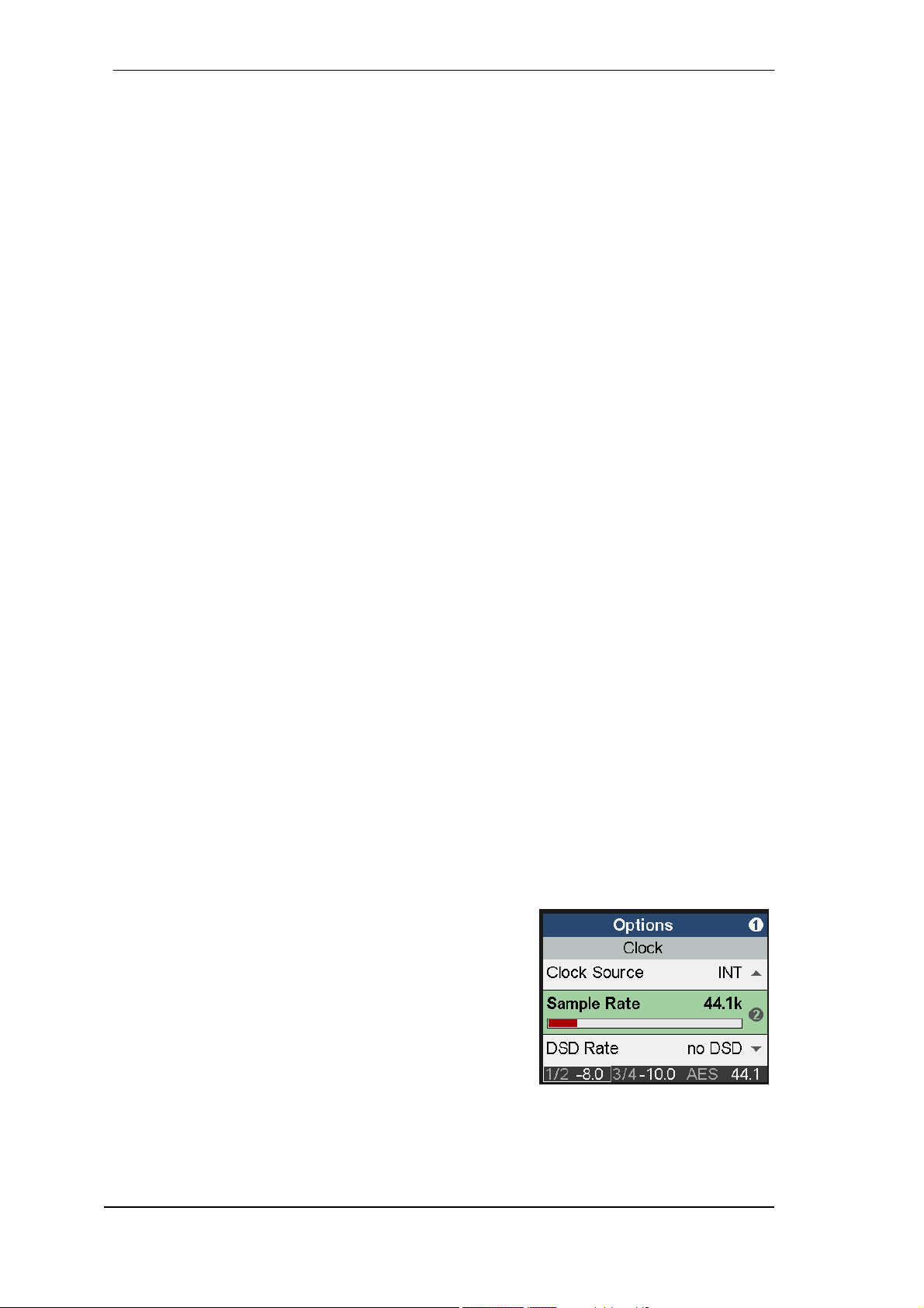
Example: Press the key SETUP. The menu Setups is now
shown. 1 within the circle on the right side indicates that by
turning encoder 1 more pages are available. Turn encoder 1
left to enter Options. Now turn encoder 2 to scroll
horizontally through all the subpages offered under Options:
Hardware/Diagnosis, Device Mode, Clock. By pressing
encoder 2 the cursor moves down, by pressing encoder 1
back up. On a selected field or entry, 2 to the right indicates
that the current parameter can be changed by turning
encoder 2. Change Clock Source and Sample Rate to see
how easy it is to select and change important settings.
18
User’s Guide ADI-2 Pro - v 1.91
Page 19
11. VOL
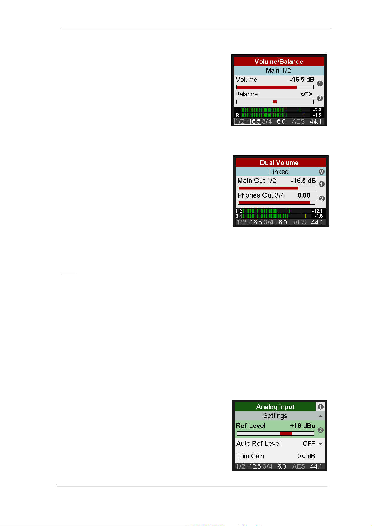
The VOL key brings up an extended volume screen with
balance control. Pushing the big Volume knob changes the
volume setting between outputs 1/2 and 3/4, which can
then be adjusted by both Volume knob and encoder 1.
Encoder 2 sets the Balance parameter.
The volume and balance setting is also found in the menu
I/O, Settings, at the end of the list.
The status bar at the bottom of the display shows the
current dB value of both volume settings. A white rectangle
around it (marker) indicates which volume the big encoder is currently set to control.
A push on encoder 1 (B) mutes the current output. The text in the blue field shows Main 1/2 -
muted. A second push exits the mute state.
Pushing the VOL key a second time enters the Dual
Volume screen, showing both volume settings at the same
time. Encoder 1 controls Volume 1/2, encoder 2 Volume
3/4, and the big Volume knob both. This allows to set the
outputs at individual levels, but also to control those
simultaneously. The linked control operates on a relative
base, with individual volumes staying intact when increased
or decreased, even to maximum and minimum.
In the Dual Volume screen, both outputs can be muted by pushing encoder 1 (B) and encoder 2
(T) respectively.
Pushing the VOL key a third time reverts to the level meter screen that has been active before.
Note
: The Dual Volume screen is not available in Balanced Phones mode. Main Out defaults to
Auto Ref Level enabled. The current volume setting is then shown as dBr (dB relative).
12. I/O
The I/O menu has all the settings for the three analog stereo I/Os Analog Input, Main Output 1/2
and Phones Out 3/4. The submenu Parametric EQ mirrors the settings done in the graphical
EQ screen. The submenus Bass/Treble and Loudness as well as some phase functions are
only found on the two analog stereo outputs.
12.1 Analog Input
12.1.1 Settings
Subpage Settings has the following entries:
Ref Level
Sets the reference level for the analog inputs 1/2. Choices
are +4 dBu, +13 dBu, +19 dBu, +24 dBu, referenced to
digital full scale level (0 dBFS).
Auto Ref Level
ON or OFF. Default: OFF. In case of overload Auto Ref
Level will switch the Ref Level to the next higher setting.
This process is repeated until +24 dBu is reached. In case
Trim Gain was active it will be set to 0 dB first.
User’s Guide ADI-2 Pro – v 1.91
19
Page 20
Trim Gain
Digital amplification of the input signal between 0 and +6 dB, in steps of 0.5 dB. Main use is to
fine-tune the input sensitivity so that it matches the reference output level of external gear.
Phase Invert
Available settings are Off, Both, Left and Right. Inverts the phase (180°) on the corresponding
channel.
AD Filter
Short Delay Sharp, Short Delay Slow, Sharp, Slow. The analog to digital conversion can be
done using four different filters. Default is SD Sharp, offering the widest and most linear frequency response and lowest latency. SD Slow causes a small drop in the higher frequency
range, but offers a less aggressive (less steep) filter. Sharp and Slow are FIR filters with different impulse responses. See the Technical Reference section for graphs illustrating the results in
frequency response and impulse response.
Dual EQ
OFF or ON. Default: OFF. When set to ON, the 5-band parametric equalizer can be set individually for left and right channel.
AD Conversion
PCM or DSD. Default: PCM. DSD will not become active at sample rates below 176.4 kHz.
When selecting DSD the current DSD rate is shown as well. It changes with the chosen sample
rate (SETUP - Options - Clock).
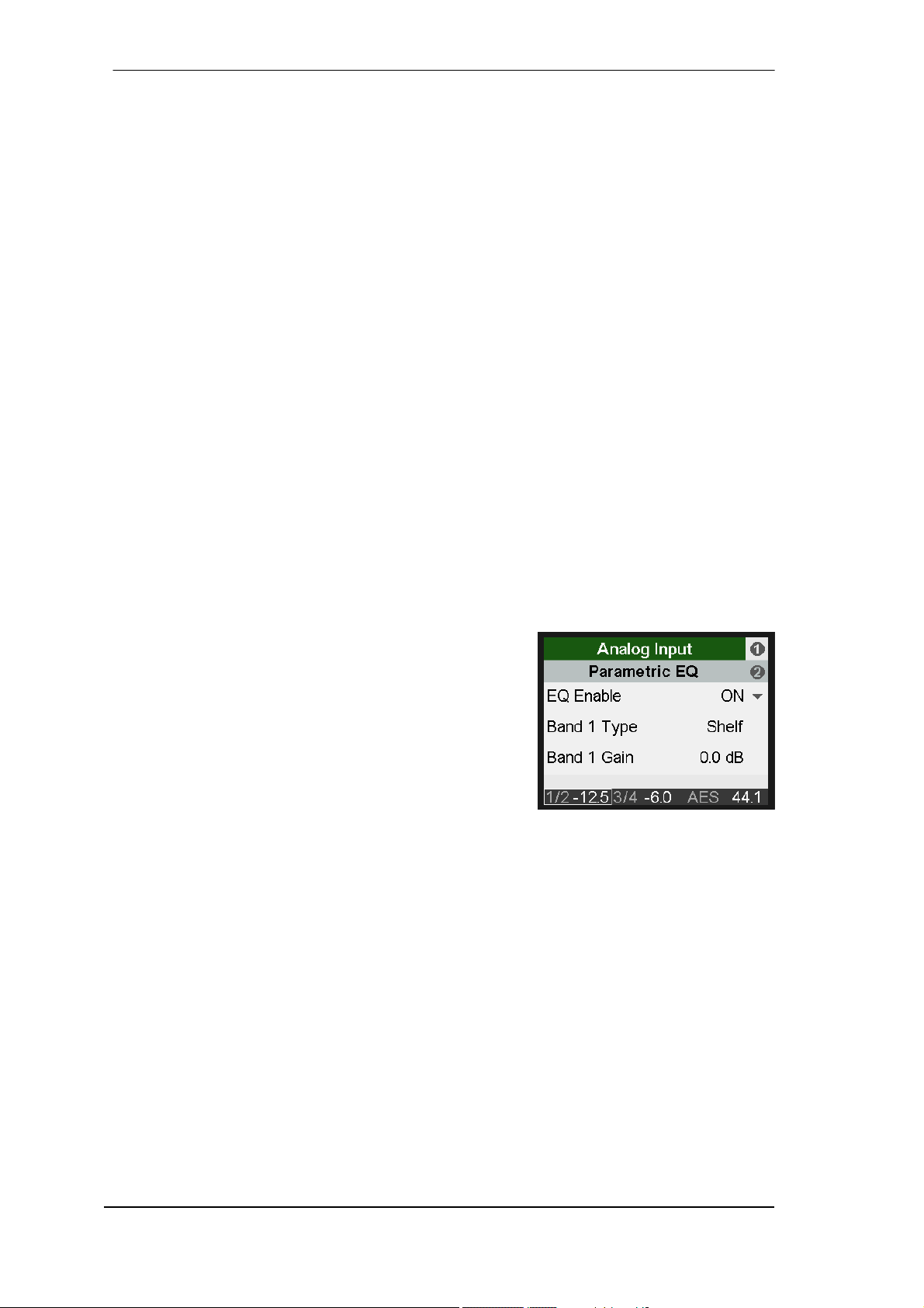
12.1.2 Parametric EQ
Subpage Parametric EQ has the following entries:
EQ Enable
ON, OFF. Default: OFF.
Band 1 Type
Available settings are Peak, Shelf, High Cut and High Pass
(Low Cut). All filters are adjustable from 20 Hz to 20 kHz, at
a Q of 0.5 to 5.0. Cut/Pass have a fixed 12 dB/oct filter
steepness.
Band 2-4 Type
Available settings are Peak and Shelf.
Band 5 Type
Available settings are Peak, Shelf or High Cut. High Cut is adjustable from 200 Hz to 20 kHz, at
a Q of 0.5 to 5.0 and a fixed 12 dB/oct.
Band 1-5 Gain
Available settings are -12 to +12 dB in steps of 0.5 dB.
Band 1-5 Frequency
Adjustable from 20 Hz to 20.0 kHz in steps between 1 Hz and 100 Hz.
Band 1-5 Q
Quality factor is adjustable from 0.5 to 5.0 in steps of 0.1. This equals a bandwidth setting of
2.54 to 0.29.
Subpage Parametric EQ R is only shown with Dual EQ set to On. It has the exact same
entries as listed above.
20
User’s Guide ADI-2 Pro - v 1.91
Page 21
12.2 Main Output 1/2
12.2.1 Settings
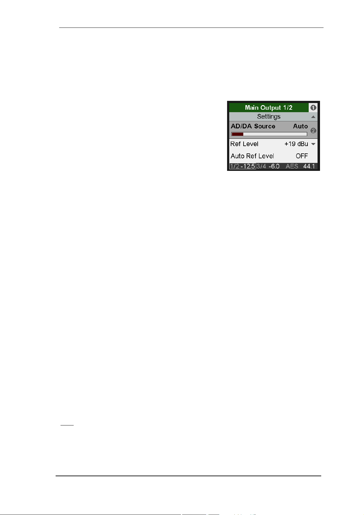
Subpage Settings has the same settings as listed for Analog Input, plus:
AD/DA Source
The source of the Main Output 1/2 signal is automatically selected based on the current mode:
Preamp mode: Analog inputs 1/2
USB: Playback channels 1/2
Dig Thru mode: current digital input signal
AD/DA converter: current digital input signal
DAC: current digital input signal and clock
The entry AD/DA Source is therefore usually grayed out.
Only in AD/DA and DAC mode the input signal can be
chosen between Auto, SPDIF, AES and Analog. This
allows to choose between all currently attached digital
input signals for conversion to output 1/2.
Ref Level
Sets the reference level for the analog outputs 1/2. Choices are +4 dBu, +13 dBu, +19 dBu, +24
dBu, referenced to digital full scale level (0 dBFS). This setting is also valid for the front output
PH 1/2, with PH 1/2 having 3 dB higher output level. This way the setting +4 dBu becomes +7
dBu output level, +19 dBu becomes +22 dBu at the phones jack. These two settings are therefore identical to Hi-Power Off and On at Phones Output 3/4.
Auto Ref Level
ON, Off. Default: ON. See chapter 21.3 for details.
Mono
OFF, ON, to Left. Default: OFF. The option to Left sends the sum of left and right channel to the
left output only.
Width
Defines the stereo width. 1.00 equals full stereo, 0.00 mono, -1.00 swapped channels.
M/S-Proc
Activates M/S processing. Monaural content is sent to the left, stereo to the right channel.
Crossfeed
OFF, 1, 2, 3, 4, 5. The Bauer stereo to Binaural crossfeed effect emulates speaker playback by
reducing the stereo width in the treble range. Adjustable in five steps.
DA Filter
Short Delay Sharp, Short Delay Slow, Sharp, NOS. The Digital to Analog Converter chip offers
several oversampling filters. Default is SD Sharp , offering the widest and most linear frequency
response and lowest latency. SD Slow causes a small drop in the higher frequency range, but
has a less aggressive (less steep) filter. Sharp and Slow are similar, but have a higher latency.
NOS is the filter with the smallest steepness and therefore affecting treble more than the others,
but offers the best impulse response. See the Technical Reference section for graphs illustrating the results in frequency response and impulse response.
: NOS deactivates the option De-Emphasis.
Note
De-Emphasis
Auto, OFF, ON. Default: Auto. For manually de-/activating the DAC's de-emphasis filter. See
chapter 34.4.
User’s Guide ADI-2 Pro – v 1.91
21
Page 22
Volume
Mirrors the direct volume control via Volume knob or encoder 1. The output level can be set
between -96 dB and +6 dB, mostly in steps of 0.5 dB. The encoders use a special accelerator
algorithm. Turning the knob fast increases the steps. It is therefore very easy to quickly jump
from 0 dB to mute by a quick left turn of the knob. At moderate turning speed the changes in dB
follow the intended volume change. Only at slower turning the finest steps will be used.
Balance
Mirrors the balance control in the VOL screen. Adjustable from L 100 (left) through <C> (center)
to R100 (right).A quick turn jumps from L or R to <C> and vice versa.
Mute
Mutes the output. Can also be controlled via the VOL screen and Remap Function Keys.
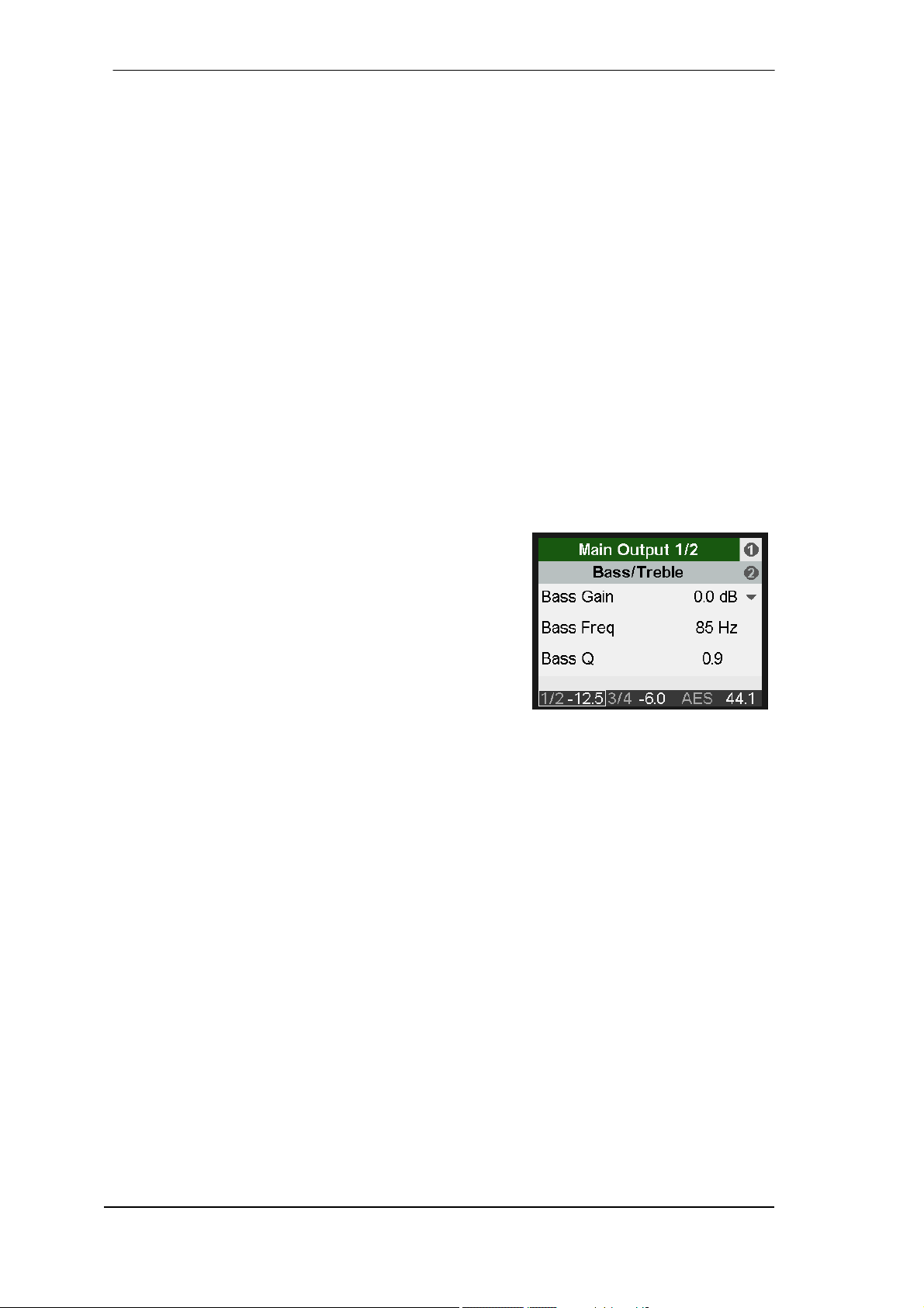
12.2.2 Bass/Treble
Subpage Bass/Treble has the following entries:
B/T Enable
OFF, ON. Default: ON
Bass Gain
Current Bass amplification for the current channels as set by encoder 1 (B). Adjustable between
-6 dB and +6 dB in steps of 0.5 dB.
Bass Freq
Corner frequency of the shelf bass filter. Adjustable from
20 Hz to 150 Hz in steps of 1 Hz. Default: 85 Hz.
Bass Q
The quality factor of the filter is adjustable from 0.5 to 1.5.
Default 0.9.
Treble Gain
Current Treble amplification for the current channels as set by encoder 2 (T). Adjustable between -6 dB and +6 dB in steps of 0.5 dB.
Treble Freq
Corner frequency of the shelf treble filter. Adjustable from 3 kHz to 10 kHz in steps of 100 Hz.
Default: 6.5 kHz.
Treble Q
The quality factor of the filter is adjustable from 0.5 to 1.5. Default 0.7.
22
User’s Guide ADI-2 Pro - v 1.91
Page 23
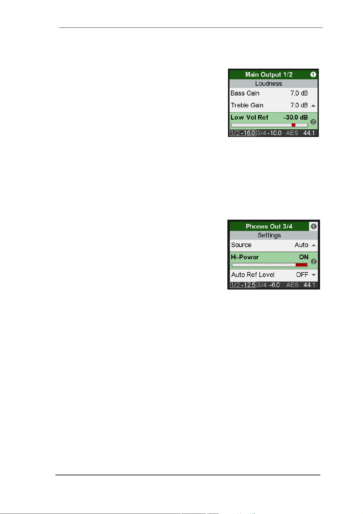
12.2.3 Loudness
Subpage Loudness has the following entries:
Enable
ON, OFF. Default: OFF.
Bass Gain
Maximum Bass amplification. Adjustable between 0 dB and
+10 dB in steps of 0.5 dB. Default: +7 dB
Treble Gain
Maximum Treble amplification. Adjustable between 0 dB
and +10 dB in steps of 0.5 dB. Default: +7 dB
Low Vol Ref
Reference level for highest Bass/Treble amplification, referenced to the Volume set in dB. Available range is -90 dB to -20 dB. Default: -30 dB. A volume setting below this point will have
maximum Bass/Treble gain, all volume settings above this point will have lower Bass/Treble
gain. 20 dB above the Low Vol Ref setting the Bass/Treble gain will be zero.
12.3 Phones Output 3/4
Subpage Settings has the same settings as listed for Main Output 1/2, plus:
Source
Default: Auto. The source of the output Phones Out 3/4 can
be chosen manually anytime. Available options are: Auto,
AES, SPDIF, Analog, USB 1/2, USB 3/4. Auto here not only
means current or available signal, but also channels 1/2.
Hi-Power
OFF, ON. Default: OFF. Reference level for 0 dBFS is +7
dBu at the output. With Hi-Power on reference level is 15
dB higher, +22 dBu.
Auto Ref Level
ON, OFF. Default: OFF. See chapter 21.3.
User’s Guide ADI-2 Pro – v 1.91
23
Page 24
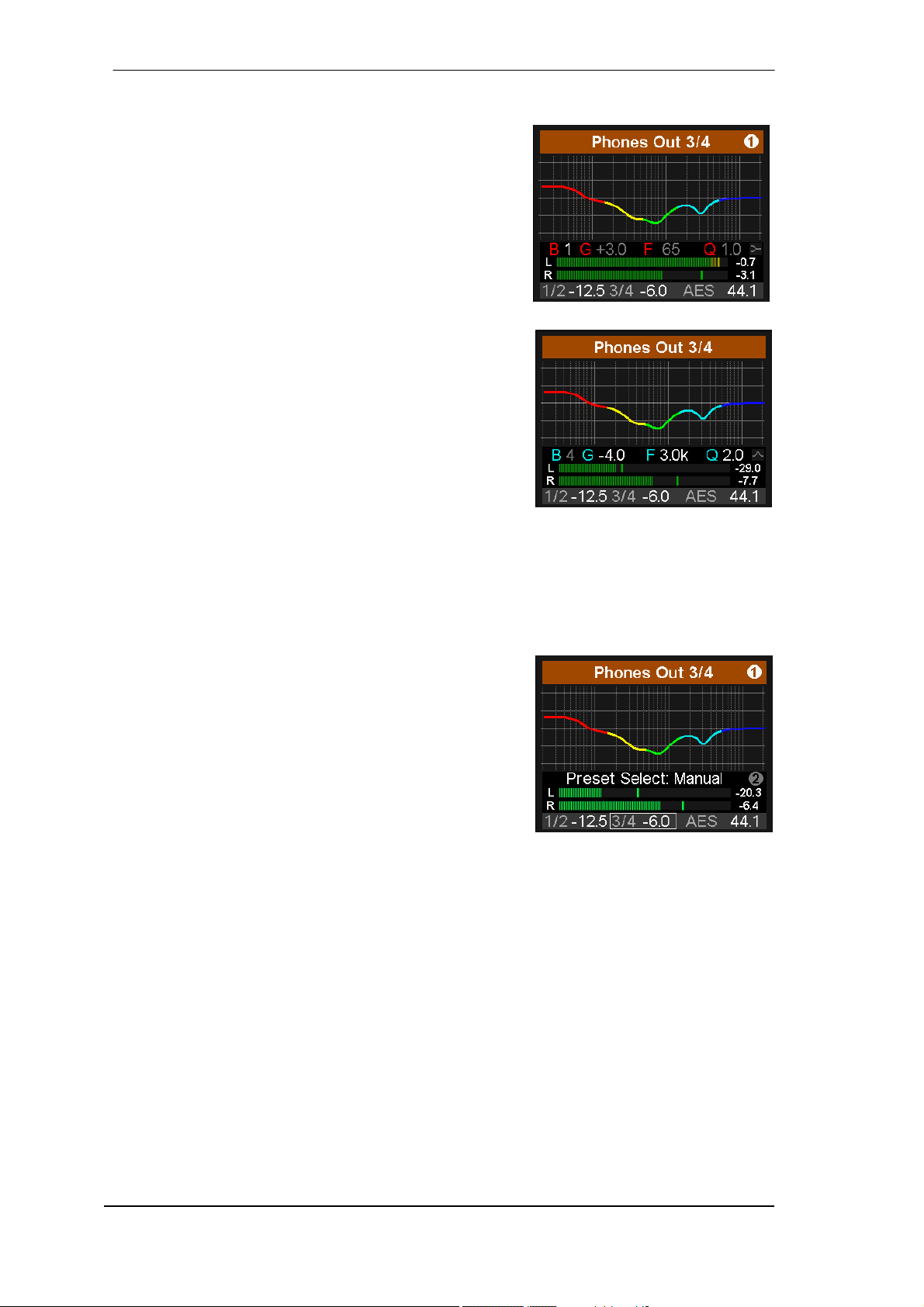
13. EQ
The key EQ brings up a graphical EQ screen (Bode plot) to
set the EQ quickly and with full overview. It is available on
all analog I/Os. The I/O - Settings submenu Parametric EQ
mirrors the settings done in this screen.
On the top level, turn encoder 1 to change between Analog
Input, Main Output 1/2 and Phones Out 3/4. Turning
encoder 2 will scroll through all 5 bands, as can be seen in
the parameter line. This function allows to see/check/verify
all parameters of all bands quickly, without the danger of
changing any of them.
Push encoder 2 to move the cursor to the parameter line,
with all values shown in white color. It is now possible to
adjust all parameters by turning the three encoders. The
Volume knob changes Gain, encoder 1 Frequency,
encoder 2 Q (Quality factor). All changes are shown in realtime as frequency response curve, making it very easy to
find the desired settings.
To change to the next band push the encoder Volume.
The five bands have different colors to clearly show what is currently selected: band 1 red, band
2 yellow, band 3 green, band 4 light blue, band 5 dark blue.
Band 1 and 5 also allow to set the filter to Peak or Shelf mode, plus Hi Pass/Hi Cut. This function is accessed by pushing encoder 2 so that the cursor moves down to the small filter symbol
in the lower right. It is no longer grayed out. Turning encoder 2 now toggles through the available settings, with the symbol changing according to the selected function.
Another push on encoder 2 changes to the graphical EQ
Preset selection screen. Turning encoder 2 will scroll
through all available EQ presets with the frequency
graphics showing the respective curve, and the parameter
line showing the preset name. In this screen Volume, volume selection and channel selection (encoder 1) are also
available.
Notes
The frequency graphics give a precise overview of the filter results. Overlapping filters influence
each other. This can be used to achieve more than 12 dB gain, or to generate difficult frequency
response optimizations.
The ADI-2 Pro has an internal headroom of 24 dB. Extreme boosts with overlapping filters could
cause an internal overload. Such an overload will be visible as it is displayed by the level meter
below the EQ, as well as the channel’s level meter. Reducing the output volume will prevent
any clipping as long as the headroom of 24 dB is not exceeded. In real-world operation that is
always the case, the ADI-2 Pro will not distort internally.
The EQ can cause distortion for the digital outputs when used on the Analog Input. Again the
level meters will clearly show this error condition. Reduce the input’s sensitivity by selecting a
higher Reference Level in such a case.
24
User’s Guide ADI-2 Pro - v 1.91
Page 25
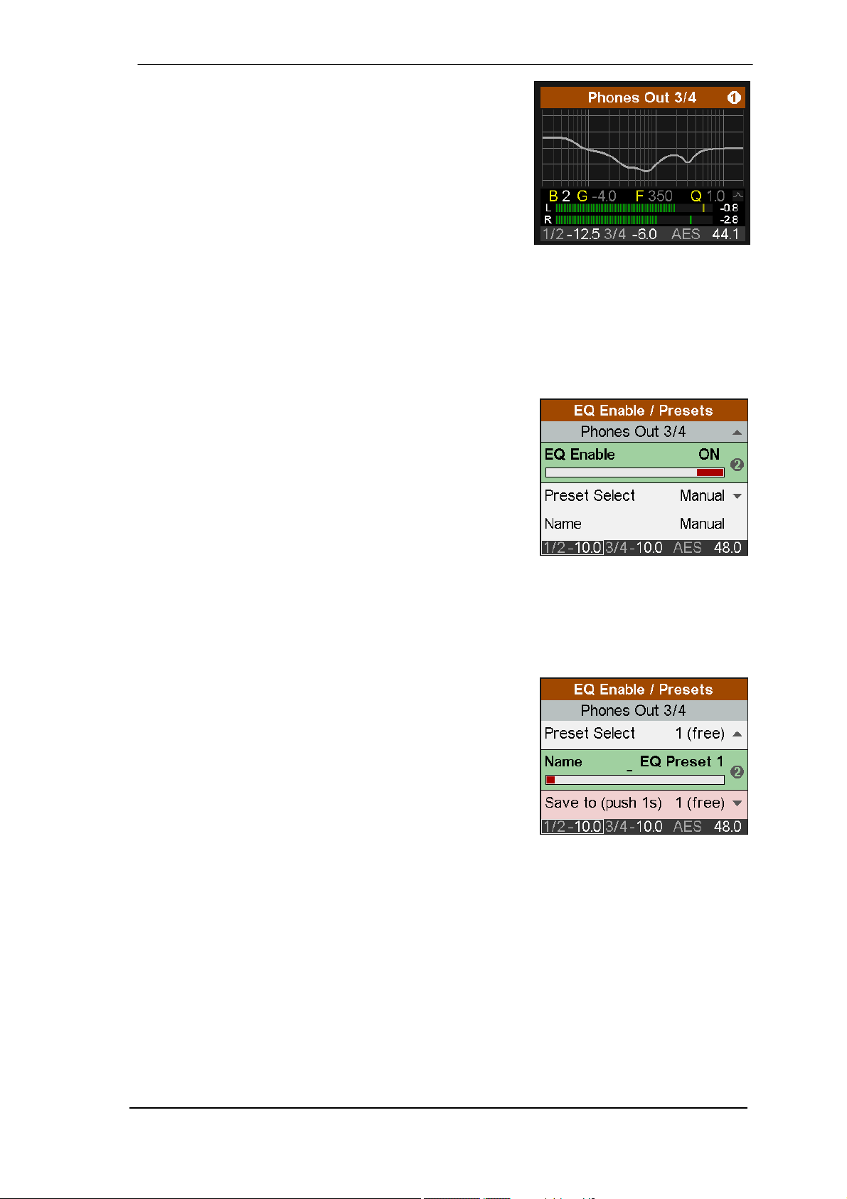
If the frequency graph is shown as grey line the EQ is
disabled. There are two ways to change this state:
¾ Push key EQ again to change to the page EQ Enable /
Presets, see below.
¾ Push key I/O, select current channels, Subpage
Parametric EQ, EQ Enable ON or OFF
Pushing the EQ key a second time brings up the EQ Enable / Presets screen. In this screen
the EQ can be switched on and off, and EQ presets can be stored and loaded comfortably.
Use encoder 1 to change between the subpages Analog Input, Main Output 1/2 and Phones
Out 3/4. These subpages have the following entries:
EQ Enable
Default: OFF. Options are ON, OFF, L, R (L and R are only
available with Dual EQ activated).
Preset Select
Load or store up to 22 different EQ settings. The first choice,
Manual, holds the current, unsaved EQ settings. The second
choice, Temp, holds the settings of a loaded and then modified Preset. This scheme lets the user easily change and
compare three different EQ settings: the manual one, the
stored preset and the modified preset, without loosing
changes while listening to a different set of EQ settings.
The presets are independent from and not stored with Setups (see chapter 14.2). EQ Presets
are therefore always available, no matter which Setup has been loaded. The Setup does include the current EQ setting, which on load is written into the memory slot Manual.
Name
Allows to edit the name of the current preset and to edit the
name during the store process. Turn encoder 2 to select a
letter, number or symbol, then press encoder 2 briefly to
enter the next sign. After the last sign the cursor jumps to the
field Store to. The name can consist of up to 14 signs.
Turning encoder 1 gives access to all existing preset names,
so copying and modifying a preset can be done more
quickly.
Changing the name is always stored immediately during
editing, without further confirmation.
Leaving this field the name is automatically adjusted to the right. Adding signs to the front and
rear is possible afterwards. A quick turn to the left brings up space, which is also used to quickly
delete letters. Available signs are:
Space, Aa to Zz, + - / ( ) * ; : . , ! # $ & < > = ' I @, 0 - 9
Save to
Use encoder 2 to select the slot where the current preset should be stored to. To store press
and hold encoder 2 for one second.
User’s Guide ADI-2 Pro – v 1.91
25
Page 26

14. SETUP
The key Setup gives access to two top level screens: Options and Load/Store all Settings. Options has the subpages Hardware/Diagnosis, Device Mode, Clock.
14.1 Options
14.1.1 Hardware/Diagnosis
Subpage Hardware/Diagnosis, has the following entries:
SPDIF In
Available settings are: Auto, Coax, Optical. Default: Auto.
SRC (Sample Rate Converter)
Available settings are: Off, AES In, SPDIF In. Note: In case a DoP signal (DSD) is detected,
SRC is automatically switched off.
Optical Out
Available settings are: SPDIF, ADAT. While the input adapts to the received signal automatically, the output needs to be switched manually. In Dig Thru mode with an ADAT signal received, the output is switched to ADAT automatically with all 8 input channels passed through.
Dig. Out Source
Default, Main Out. Copies the signal Main Out 1/2 (including EQ and volume) to the digital outputs AES and SPDIF/ADAT. Useful when connecting active monitors with digital inputs.
Display Mode
Available settings are: Default, Dark. The dark scheme inverts the white background and black
numbers/text to black background and light-grey numbers/text.
Meter Color
Green, Cyan. Default: Green. Changes the color of the meter screens for PCM and DSD mode.
Remap Keys
OFF, ON. Default: OFF. Allows to assign 26 different functions/actions to the four function keys,
configurable via the following four entries:
VOL Key, I/O Key, EQ Key, SETUP Key. Available functions/actions:
Setup 1 to 9, Mono 1/2, Mono 3/4, Mono to L 1/2, Mono to L 3/4, Mute 1/2, Mute 3/4, Mute all,
Loudness 1/2, Loudness 3/4, EQ In 1/2, EQ Out 1/2, EQ Out 3/4, BT Out 1/2, BT Out 3/4,
EQ+B/T+Ld 1/2, EQ+B/T+Ld 3/4, Toggle Ph/Line.
The original function of the key, entering the menu, is still available by pushing the key for half a
second.
LCD Brightness
Adjustable from 20% to 100%. Default is 80%.
LCD Tint Control
Adjustable from -8 (yellow) to 8 (blue). Enables compensation of the display's colour deviation
as well as suiting the user's taste.
Test Results
Please ignore. For internal use only.
SW Version
Shows the current version number and date of the internal DSP software.
26
User’s Guide ADI-2 Pro - v 1.91
Page 27
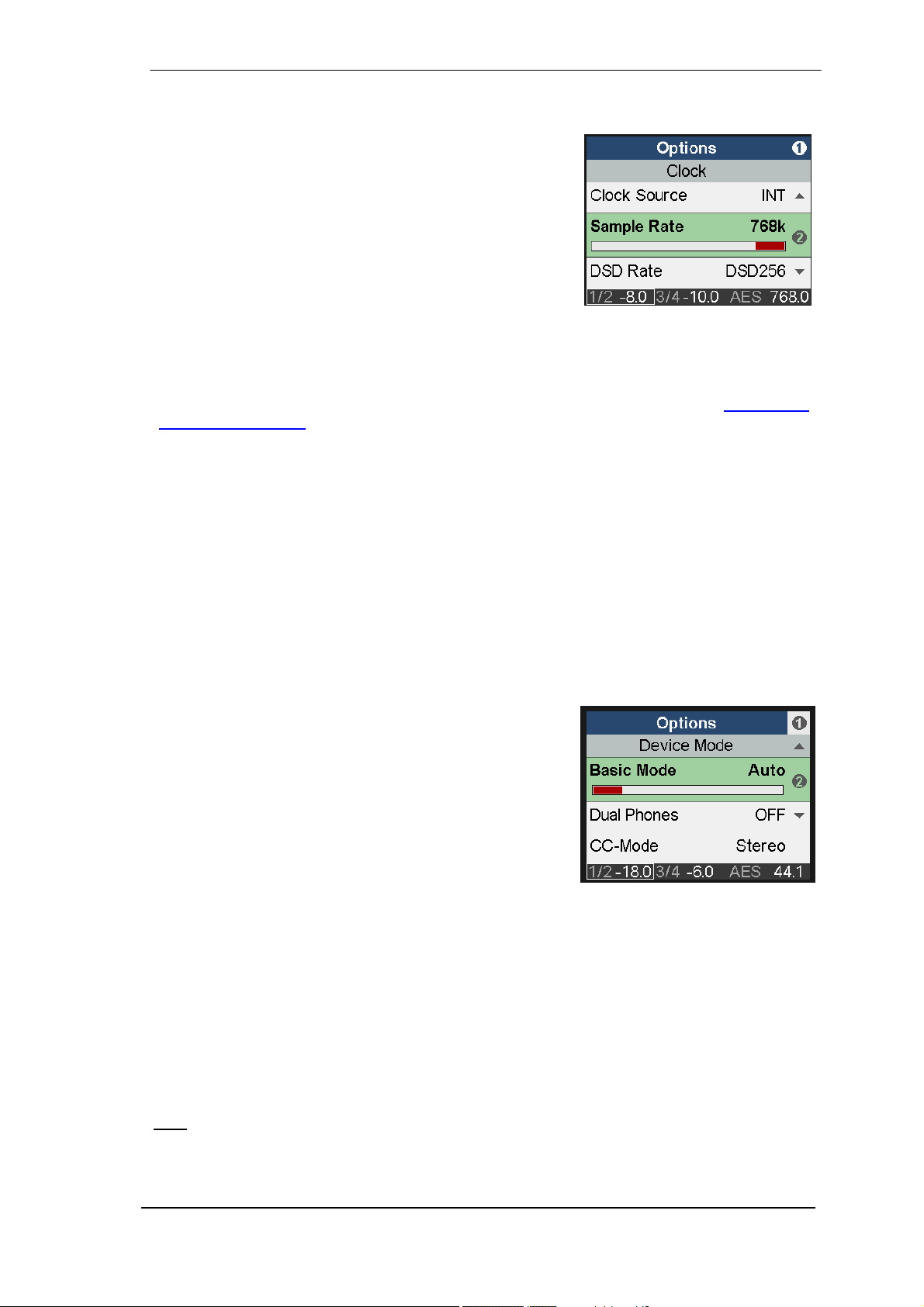
14.1.2 Clock
The subpage Clock has the following entries:
Clock Source
Choices are Auto, INT (Internal, Master), AES, SPDIF.
Sample Rate
Choices are 44.1, 48, 88.2, 96, 176.4, 192, 352.8, 384,
705.6 and 768 kHz. When clocked externally the ADI-2 Pro
will recognize and handle other frequencies as well, for
example 32, 64 and 128 kHz.
When using 352.8 or 384 kHz sample rate the level meter display will show a single channel of
audio sent out from SPDIF, or received in case a signal of 192 kHz sample rate is attached. The
reason is that the ADI-2 Pro includes a special SMUX mode. When run at Octa Speed, the ADI-
2 Pro will split the data of the left analog input channel to the AES/SPDIF output channels left
and right, at half the sample rate – 192 kHz. Using measurement software like HpW Works
(www.hpw-works.com) which supports this mode (2x speed), and any 192 kHz capable RME
audio interface, one can perform analog measurements with 384 kHz sampling rate bandwidth
over SPDIF – of at least one analog channel.
The big advantage compared to a direct USB connection: using SPDIF optical the tested device
is galvanically isolated from the measuring system (interface/computer), a crucial requirement
when probing in the extreme areas that the ADI-2 Pro allows for.
14.1.3 Device Mode
The subpage Device Mode has the following entries:
Basic Mode
Choices are Auto, AD/DA, USB, Preamp, Dig Thru and DAC. See chapter 17.
Dual Phones
OFF, ON. Default: OFF. With Dual Phones ON the phones
output PH 1/2 will be active. Default state is Off, as PH 3/4
is the main phones output and should be used exclusively
unless two phones are to be connected.
If Dual Phones is on and two phones are plugged in, a push
on VOLUME toggles between 1/2, 3/4 and linked volume
control (with the marker over both). When VOLUME is
turned the Dual Volume screen is shown then.
CC-Mode
Choices are Stereo and Multi-channel. The ADI-2 Pro supports two Class Compliant modes: 2
channel I/O, which allows to use sample rates up to 768 kHz even with iOS devices, and 6/8
channel mode to give access to all I/Os simultaneously. In multi-channel mode the sample rate
is limited to 192 kHz. To be able to change the mode USB must be disconnected.
Bal Phones Mode
OFF, ON, Auto. Default: OFF. In Balanced Phones mode output PH 3/4 carries the left channel,
output PH 1/2 the right channel. See chapter 18 for details. When Auto is selected, the balanced phones mode is automatically activated as soon as both Phones outputs detect a connector being plugged in. This feature temporarily deactivates DSD Direct mode if active.
: When active, the rear analog outputs are muted automatically.
Note
,
User’s Guide ADI-2 Pro – v 1.91
27
Page 28
Phones <=> Line
OFF, 1/2, 3/4, 1/2+3/4. Default: OFF. Activates the ability to toggle mute between Phones Out
and rear Line Out. Pushing the VOLUME knob for half a second will then switch between loudspeakers connected to the rear and phones plugged into the front. This function can also be
controlled by one of the four function keys via Remap Function Keys.
Mute v. TRS 1/2
ON, OFF. Default: ON, but grayed out. As soon as a plug is detected in PH 1/2 the rear outputs
1/2 are muted. Note: This function requires Dual Phones to be on to become accessible. With
Mute v. TRS 1/2 ON the channels Phones 1/2 and Mains Out 1/2 have separated settings. Although both outputs alternately play back the same signal, all settings (Settings, EQ, BT) can
be different, and are separately stored in the background.
Mute v. TRS 3/4
ON, OFF. Default: ON. If set to ON a plug detected in PH 3/4 mutes the rear outputs 1/2.
DSD Direct 1/2
OFF, ON. Default: OFF. When activated a DSD playback will use DSD Direct mode over the
rear outputs 1/2. As DSD Direct bypasses all DSP calculations and volume control, the only
way to change the output volume is by setting different reference levels. Therefore in DSD Direct mode Phones outputs 1/2 are disabled.
DSD Filter
When DSD Direct mode is active, high-frequency noise filters reduce out-of-band noise, which
might have negative impact on other equipment. While 50 kHz is optimized for DSD64 and 150
kHz for DSD 128 and 256, the user can freely try both at any DSD rate.
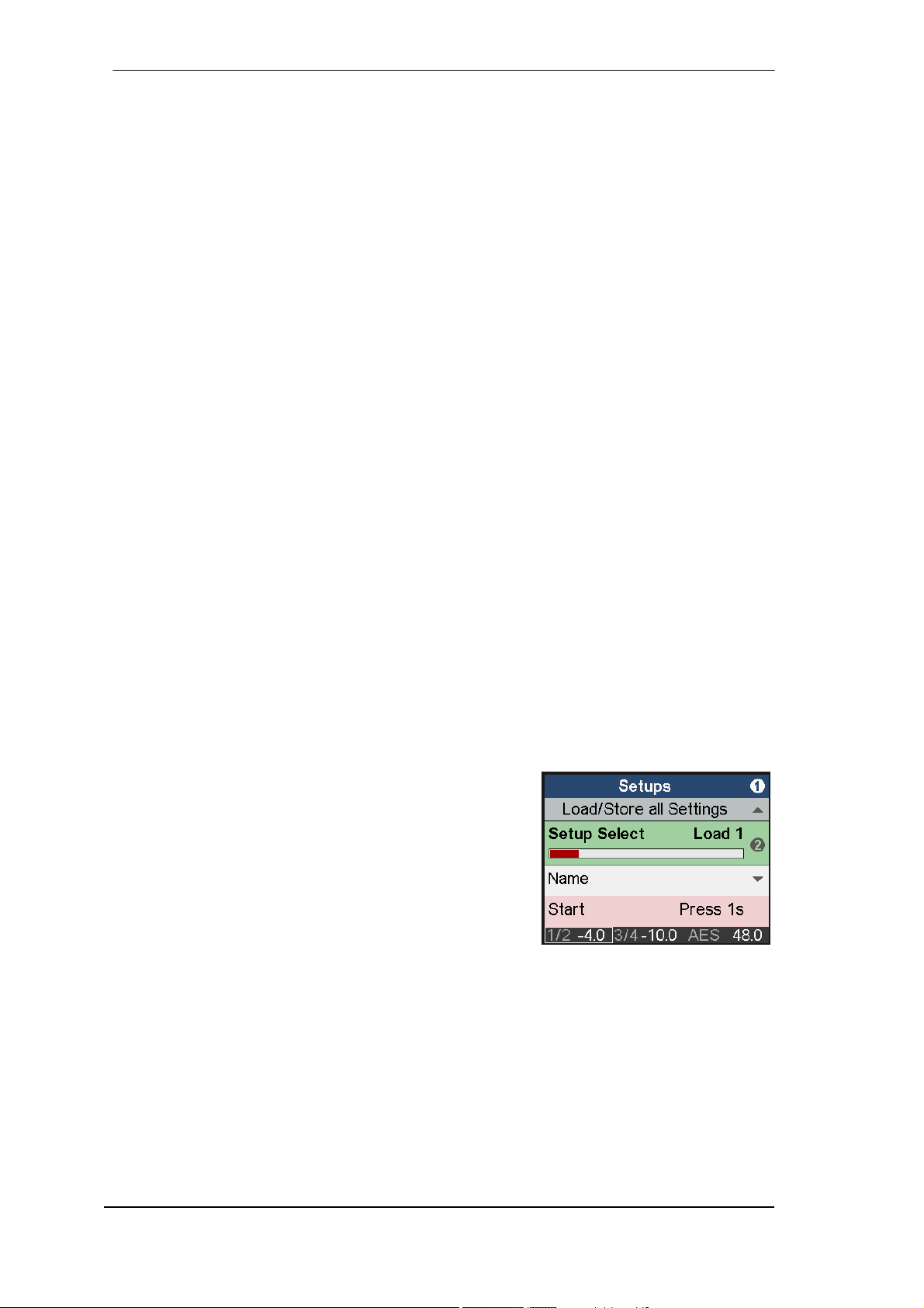
14.2 Load/Store all Settings
This option allows to save the whole state of the unit as Setup in up to 9 different memory slots.
The EQ Presets are not included, they are stored separately and are available for any setup.
The current state of the EQ is also stored. During load of a Setup the EQ is written to the mem-
ory slot Manual.
The page Setups, Load/Store all Settings, has the following entries:
Setup Select
Choices are Load 1-9, Factory (Reset All) and Store 1-9.
Name
Allows to edit the name of the Setup during the store
process. To edit an existing name load the respective Setup
and store it on the same memory slot with edited name. See
EQ - Name for details about the Edit operation.
Start
Press 1s. Pressing and holding encoder 2 for at least one second triggers the action selected
(Load or Store).
Returning to Factory State
In case a total reset is desired: hold encoder 1 and the VOL button pushed while turning on the
unit. This will reset all current settings to factory default. User-stored Setups and EQ presets are
not affected. The same action is performed by loading Factory via Setup Select. Note that the
reset will be incomplete when the unit is connected to USB while performing the reset.
When holding encoder 1, 2 and the VOL button pushed while turning on the unit, user-stored
Setups and EQ presets are still not affected, but their names are reset as well.
28
User’s Guide ADI-2 Pro - v 1.91
Page 29
15. Meter Screens
The ADI-2 Pro has four different meter screens: a global level meter that shows all signal levels
of all I/Os simultaneously, an Analyzer showing the audio signal content on the analog inputs
and both analog outputs 1/2 and 3/4, a state overview showing the digital states of AES, SPDIF
and USB, and a dark Volume screen with comprehensive information.
Pushing the small encoder 1 or 2 while any meter screen is active cycles through all meter
screens. To quickly call them up simply press any of the 4 buttons one or two times.
15.1 Global Level Meter
Shows the signal present at all inputs and outputs. The
upper labels refer to inputs Analog, AES and SPDIF, then
outputs Analog 1/2, Analog 3/4, AES and SPDIF.
At sample rates above 192 kHz AES and SPDIF are
grayed out as they are no longer functional.
These are peak level meters with peak hold function,
bandwidth limited to 40 kHz at higher sample rates.
15.2 Analyzer
The Analyzer is one of the main features of the ADI-2 Pro. Thanks to the high-resolution IPS
panel even smallest details are clear to see. Music content analysis is possible even when
viewed from a greater distance.
The Analyzer is based on RME’s famous Spectral Analyzer in DIGICheck. It uses 29 biquad
bandpass filters for high separation between the bands, providing outstanding musical visualization. Using carefully selected attack and release times the display is responsive, but still easy
to read. On top it uses RME’s own Max LR technique to prevent 6 dB higher level display for
monaural signals, and zero display with out–of-phase signals.
The Analyzer operates at any sample rate, and even with
DSD. There are no parameters to change, and the shown
frequency range is always the human audible range, 0 up
to 20 kHz.
To be able to also show DC content the lowest band is not
a band-pass filter, but a low pass, catching the whole
range from 0 Hz up to 20 Hz. With some unusual signals it
therefore can happen that the level shown will be a bit
higher than expected.
As opposed to most other solutions no FFT (Fast Fourier Transform) is used. RME's Spectral
Analyzer performs a true band-pass filter calculation, as in professional hardware devices. The
frequency distance between the filters is scaled matching human hearing. The highly optimized
code allows to run a 30 band analyzer with 60 dB range, sharp filters and 0.5 dB steps accuracy
per band, on the ADI-2 Pro DSP, even at 768 kHz sample rate.
The most important application using a Spectral Analyzer is the visualization of frequencies and
levels found in music or speech. The Analyzer shows levels and frequencies even at the edge
of the human ear's abilities – or that of the used speakers and headphone. The visual display
helps to train ones ears, makes coarse errors visible, and shows what sometimes might stay
unnoticed. For example many speakers won't let you hear frequencies below 30 Hz. Simply
look on the Analyzer to see what's going on in the underground.
User’s Guide ADI-2 Pro – v 1.91
29
Page 30

15.3 State Overview
The State Overview screen is a typical RME feature. Since 20 years we prefer to give our customers more information at hand than just ‘something there’. The Settings dialogs of our audio
interfaces include detailed Input Status analysis to simplify setup and ease trouble-shooting.
Additionally RME provides a free tool with any audio interface, DIGICheck, which analyzes levels, Channel Status and bit stream content, the true hardware sample rate and much more.
When the ADI-2 Pro is connected but no sound can be
heard then RME’s analysis tools come to the rescue. The
State Overview screen is there to track down the problem in
an easy to understand and efficient way. Although it might
look simple (fully intentional!), it includes detailed analysis
that outperforms any other similar device.
Shown are the current states of the digital inputs SPDIF
optical and coaxial, AES, USB connection and the audio
transmitted, and the SRC. The current Clock source is
mentioned in full length, although this information is found
abbreviated in the status bar at the bottom.
The status bar always shows the current volume setting of outputs 1/2 and 3/4, the currently
selected output for the Volume knob by a marker around the outputs, the current clock source,
and the current sample rate. In case of Sync problems the sample rate will either fluctuate or be
shown in red – or both. This information is available in nearly all screens, and helps to get a
quick overview of the current state. The State Overview screen now extends this information in
great detail.
The currently selected SPDIF input, manually or automatically, is shown as SP op or SP co
(optical or coaxial). The SYNC column shows No Lock, which equals no signal present, as
And lock and sync, according to the current clock state of the respective input. Note that with
SRC active the respective input will always show lock, not sync, because the phase relation
between internal and external clock has no meaning anymore.
In case of USB conn (connected) is shown as soon as a valid USB connection is established.
The column SR shows the hardware measured sample rate for the SPDIF and AES input. It will
even display values that can not be set at the ADI-2 Pro itself, for example 32, 64 and 128 kHz.
In case of USB the sample rate is not measured but set by the external computer or iOS device,
and can be verified here, up to the highest value of 768 kHz.
The State column shows the Channel Status, Consumer (cons) or Professional (pro), for incoming SPDIF and AES signals. In case a DoP (DSD over PCM) header is detected DSD is
shown. With USB the state column shows the current channel mode, 2/2 or 6/8, or DSD if a
DoP header is detected.
The Bit column shows the amount of bits found in the SPDIF and AES audio signal. Note that a
24 bit signal that is shown as 16 bit is indeed 16 bit, but a signal shown as 24 bit might contain
only 16 bit real audio plus 8 bits of noise…
But SPDIF and AES can also transport AC-3 and DTS encoded surround sound. This signal
sounds like chopped noise at full volume. Therefore the ADI-2 Pro receiver circuit checks the
Non-Audio flag within the Channel Status. If found the signal is already muted directly in the
receiver. An error message is shown in red colour in the lowest line, saying SPDIF NONAUDIO, explaining why there is no sound at the analog outputs despite a valid input signal.
Finally also Emphasis, a special treble boosting equalization method from the early days of
digital audio, is detected and shown as SPDIF WARNING EMPHASIS. See chapter 34.4.
- -.
30
User’s Guide ADI-2 Pro - v 1.91
Page 31

The inclusion of the SRC status helps to find simple errors that can happen due to the many
options of the ADI-2 Pro, which naturally reside in different parts of the menu structure. For
example the SRC might be active, but SPDIF signal is dead audio-wise. A quick glance at the
State Overview will reveal that the SRC was set to work on the wrong input (AES)…
15.4 Dark Volume
This screen has been added as alternative to the other
meter screens, which even with the dark theme selected
might be disturbing in some situations. Dark Volume shows
the current volume setting of both analog outputs, their
current reference level setting, the amount of Bass/Treble
gain applied, and the Balanced Phones mode. It is low in
brightness, still fully readable in bright environments, and
has zero flickering or moving elements (level meters).
Volume and Bass/Treble adjustments happen right in this
screen, which makes its functionality not only visually
pleasing.
Despite this screen having no level meters, overloads caused by Volume, PEQ or Bass/Treble
are easy to recognize. The big gain numbers are coupled to the over detection of the analog
outputs. They change their color to red when overload occurs.
As with the other meter screens, once selected it becomes the default screen, automatically
shown after power-up or when leaving a menu.
16. Warning Messages
The ADI-2 Pro will show different warning messages and provide guidance in certain cases.
Hi-Power Mode Active
When Hi-Power mode is active with the Volume set higher
than -15 dB and a phone is plugged in, this message reminds
the user to check the current volume setting, and to make
sure the used headphone will stand the high output power
without getting destroyed. The audio signal is held at a low
volume until the gain is set to -15 dB or below. The Volume
knob is active on the current phones output and can be used
to turn down the volume. Once -15 dB is reached the volume
is ramped up to the current gain.
Pressing encoder 1 removes the message immediately, with volume ramped up within 2 seconds to the set value.
The message will also vanish when the phone is unplugged again.
This message is not shown when Volume is set to -15 dB or lower, or when the device is
switched on while the phones are already connected.
User’s Guide ADI-2 Pro – v 1.91
31
Page 32

Dual Phones Mode required
Phones output PH 1/2 is considered an additional output for
two specific cases: usage of two headphones and balanced
phones operation. Therefore plugging in phones into output
PH 1/2 brings up a warning that this output is coupled to the
rear outputs, and should only be used if required.
PH 1/2 stays deactivated until Dual Phones mode has been
activated via SETUP.
Overload / Short detected
An internal overload can be caused by too high output levels
and too low load impedance. A short circuit in the TRS plug
will also trigger the overload detection. In such a case the
relay will permanently disconnect the phone from the Extreme
Power output stage. If the phones plug is removed and
plugged in again after one second, the unit will activate the
phones output again.
This scheme has been introduced to force the user to check
cabling and connection. For example, a TRS plug not fully
inserted might stay unnoticed but can cause a short circuit.
DC detected
DC detection is crucial to prevent the sensitive phones drivers
from being destroyed by inaudible currents flowing through
them. As the ADI-2 Pro is fully DC coupled from DAC to
phones output, a digital full scale signal with 0 Hz would
produce up to 15V DC at the outputs, and destroy any
attached phone immediately. In case the power output stage
fails the same could happen. Therefore the phones outputs
will switch off with 1.8V DC detected.
Power Fail
In case the operating voltage drops below 9.3V the internal
power supply of the analog I/Os is switched off (overcurrent
protection). However the digital part will operate even with
only 5V. Therefore connecting a wrong power supply could
pretend a fully working unit - which just doesn't receive or
emit any audio. This warning screen informs about the
undervoltage problem.
Internal Error
During power-on the unit performs a self-test. When this test
fails USB will be deactivated, with record and playback no
longer functional. In such a case please contact your local
RME distributor.
32
User’s Guide ADI-2 Pro - v 1.91
Page 33

The ADI-2 Pro also shows certain Info Messages during normal operation, to explain the cur-
rent state and to point out possible problems.
In AD/DA and DAC mode, a Non-Audio Channel Status causes the DA section to be muted. An
info message Non-Audio signal at SPDIF input gives a hint why there is currently no analog
audio at the outputs present.
In USB mode, an Emphasis Channel Status brings up the info message Emphasis detected at
SPDIF input. This reminds the user that the Emphasis indication gets lost when recording
through a computer.
On any change of the Basic Operation mode, the new mode is shown for 2 seconds in the display (Preamp mode active, AD/DA mode active, USB mode active, Dig Through mode active).
When plugging in two connectors into the front with Balanced Phones mode Auto active, Bal-
anced Phones mode active will be shown briefly.
17. Modes
17.1 Auto
The ADI-2 Pro is an AD/DA converter, USB audio interface, USB DAC, analog headphone amp,
format converter and digital monitoring device, with extended flexibility and versatility, equipped
with 5 input sources and 6 output paths. Usually that means an overflowing menu structure and
endless searches in the menus to get it working in even simple applications.
To prevent such frustrating situations the ADI-2 Pro includes an (and ships with activated) Auto
setup mode. When SETUP – Options – Device Mode – Basic Mode is set to Auto, the unit will
turn into different operating modes depending on the connected cables:
x Preamp: Analog in to Analog out. This mode is active when no digital input signal and no
USB is detected.
x AD/DA: Converter Mode, analog in to all digital outs, digital in to all analog outs. This mode
becomes active as soon as a digital signal is attached. This signal will also become the signal source. In case more than one digital signal is found the user has to manually select the
source to be monitored. The SRC is active as default and assigned to SPDIF. Clock mode
is slave to AES in, but will adapt to the detected source (Auto).
x USB: or interface mode, or USB DAC. If USB is detected all inputs are routed to USB, all
outputs are fed from USB. USB has priority over the converter mode. In Setup the unit can
be configured as 2-channel or 6/8-channel device.
There are two more modes available, but not via Auto, only by manually activating them. Digital
Through Monitor (automatic clock and source selection of the digital inputs plus internal D to D
routing) allows to insert and monitor AES, SPDIF and ADAT signals. In case of ADAT only
channels 1/2 are monitored, but all 8 channels are passed through. DAC combines clock and
input source selection for easiest operation in home and HiFi usage.
In all modes (except DAC) Phones Out 3/4 is freely configurable, any possible source can be
monitored independently. This includes USB: when selecting one of the above modes manually
all inputs are still transferred to USB, and playback is possible when manually selecting USB as
signal source on analog output 3/4.
The unit remembers all settings, and loads these automatically when it is switched on again.
The following pages show block diagrams and include more details of these modes.
User’s Guide ADI-2 Pro – v 1.91
33
Page 34

17.2 Preamp
Preamp: Analog in to Analog out (internal digital routing).
This mode can be activated manually by selecting Basic Mode – Preamp. The device enters
Preamp mode automatically when Basic Mode is set to Auto and no digital input signal and no
USB is detected.
Analog input signals are automatically routed to the analog outputs. Use an analog source to
hear it via the rear analog outputs or the headphone outputs, amplified, EQ’d, processed, level
shifted and impedance or unbalanced/balanced converted.
Default sample rate in this mode is 192 kHz, which represents the optimum in fully available
DSP power and superior sonic transparency. Changing the sample rate manually is possible
and the new value will be remembered.
The below diagram shows that the analog input is sent to all digital outputs simultaneously. Any
DSP setting (EQ, phase etc.) of the analog input will affect all outputs. Furthermore the processed input signal is then processed independent for both analog outputs once more with the
respective output settings.
Note
: To simplify the diagram and to maintain overview USB record is not shown. In all modes
all input signals are sent over USB to the host. In multi-channel mode three separate stereo
pairs, in stereo mode only the stereo analog input.
USB Playback channels 3/4 can only be monitored in multi-channel mode. In stereo mode selecting USB 3/4 plays channels 1/2.
The option Digital Out Source - Main Out (SETUP – Options – Hardware/Diagnosis) sends the
processed signal Main Out 1/2 to the digital outputs AES, SPDIF and ADAT, for example to
connect active monitors having digital inputs.
34
User’s Guide ADI-2 Pro - v 1.91
Page 35

17.3 AD/DA Converter
AD/DA: Converter Mode, analog in to all digital outs, digital in to all analog outs.
This mode can be activated manually by selecting Basic Mode – AD/DA. The device enters
AD/DA mode automatically when Basic Mode is set to Auto and a digital input signal is de-
tected.
The detected digital input signal will also become the signal source. In case more than one digi-
tal signal is found the user has to manually select the source to be monitored (I/O – Output
Channel - Settings – Source). The SRC is active by default, assigned to SPDIF, but switched off
automatically if a DoP signal (DSD) is detected. Clock mode is slave to AES in, but will adapt to
the detected source (Auto).
Note
: To simplify the diagram and to maintain overview USB record is not shown. In all modes
all input signals are sent over USB to the host. In multi-channel mode three separate stereo
pairs, in stereo mode only the stereo analog input.
USB Playback channels 3/4 can only be monitored in multi-channel mode. In stereo mode selecting USB 3/4 plays channels 1/2.
The option Digital Out Source - Main Out (SETUP – Options – Hardware/Diagnosis) sends the
processed signal Main Out 1/2 to the digital outputs AES, SPDIF and ADAT, for example to
connect active monitors having digital inputs.
User’s Guide ADI-2 Pro – v 1.91
35
Page 36

17.4 USB
USB: interface mode.
This mode can be activated manually by selecting Basic Mode – USB. The device enters USB
mode automatically when Basic Mode is set to Auto and a USB connection is detected. USB
has priority over AD/DA mode.
In USB mode all inputs are routed to USB, all outputs are fed from USB. In SETUP – Options –
Device Mode – CC-Mode the unit can be configured as 2-channel (Stereo) or 6/8-channel
(Multi-channel) device. Sample rates higher than 192 kHz and DSD128/256 are only available
in 2-channel mode, which is why this mode has been chosen as default.
Class Compliant Stereo mode
In 2 channel / Stereo mode only the analog inputs are sent as USB record signal, and the stereo USB playback signal is available simultaneously at all analog and digital outputs.
The two block diagrams show the small differences between both modes.
USB Playback channels 3/4 can only be monitored in multi-channel mode. In stereo mode selecting USB 3/4 plays channels 1/2.
The option Digital Out Source - Main Out (SETUP – Options – Hardware/Diagnosis) sends the
processed signal Main Out 1/2 to the digital outputs AES, SPDIF and ADAT, for example to
connect active monitors having digital inputs.
36
User’s Guide ADI-2 Pro - v 1.91
Page 37

Class Compliant Multi-channel mode
With USB connected all digital and analog inputs (6 channels) are routed to USB recording. In
the same way USB playback will feed all outputs separately (8 channels).
In 6/8 channel mode all I/Os can be used separately. Phones output 3/4 provides USB playback
of channels 1/2 when its Source is set to Auto (default).
The option Digital Out Source - Main Out (SETUP – Options – Hardware/Diagnosis) sends the
processed signal Main Out 1/2 also to the digital outputs AES, SPDIF and ADAT, for example to
connect active monitors having digital inputs. The playback channels 5/6 and 7/8 can not be
used anymore.
User’s Guide ADI-2 Pro – v 1.91
37
Page 38

17.5 Digital Through Mode
This additional mode is a manual option only, it is not available via Basic Mode Auto. It has to
be activated manually by selecting Basic Mode – Dig Thru.
The purpose of the Digital Through Monitor is exactly what its name describes. A single digital
input signal is passed through the unit and can be monitored on the analog outputs at the same
time. Automatic clock and source selection of the digital inputs plus internal D to D routing allows to insert and monitor AES, SPDIF or ADAT signals. With ADAT only channels 1/2 are
monitored, but all 8 channels are passed through.
The digital signal is not simply patched from input to output, but completely rebuilt. It gets totally
refreshed by SteadyClock III, and even clock decoupled or up-/down sampled with the SRC
turned on. Without SRC the included 24 bit audio data is passed on bit-transparent.
As any digital input signal becomes available at all three digital outputs, Dig Thru mode also
offers digital format conversion as well as a distribution feature (one source to three destinations).
Note
: To simplify the diagram and to maintain overview USB record is not shown. In all modes
all input signals are sent over USB to the host. In multi-channel mode three separate stereo
pairs, in stereo mode only the stereo analog input.
USB Playback channels 3/4 can only be monitored in multi-channel mode. In stereo mode selecting USB 3/4 plays channels 1/2.
The option Digital Out Source - Main Out is not available in this mode.
38
User’s Guide ADI-2 Pro - v 1.91
Page 39

17.6 DAC
This additional mode is a manual option and not available via Basic Mode Auto. It must be activated manually by choosing Basic Mode – DAC.
This mode simplifies operation and source selection. Using the ADI-2 Pro as a typical HiFi DAC
becomes a breeze:
¾ Simple 2 channel stereo operation
¾ Easiest switching between the sources to be monitored, like USB and SPDIF
In this mode the source selection of Main Out 1/2 also defines the clock source of the unit.
Changing SPDIF/AES the ADI-2 Pro will automatically sync to SPDIF/AES input signal, this
working in clock mode slave. When switching to USB the unit operates in clock mode master
(USB asynchronous).
In mode DAC the AD conversion always uses the last set sample rate of USB. Phones Out 3/4
always monitor the same source signal as Main Out 1/2, but still have fully independent settings
(Vol, EQ etc).
The option Digital Out Source - Main Out (SETUP – Options – Hardware/Diagnosis) sends the
processed signal Main Out 1/2 also to the digital outputs AES, SPDIF and ADAT, for example to
connect active monitors having digital inputs.
User’s Guide ADI-2 Pro – v 1.91
39
Page 40

18. Balanced Phones Mode
In balanced operation, two identical power amplifiers are used to drive one side of the phones
each. Compared to normal, grounded operation, the voltage seen by the phone driver/speaker
is doubled. The power sent to it is even quadrupled.
With the comparatively low power required by headphones, and its already powerful Extreme
Power outputs, the balanced phones mode of the ADI-2 Pro has not been optimized for more
power, but more fidelity. See chapter 34.3 for all the details behind the extraordinary Advanced
Balanced mode implemented into the ADI-2 Pro.
In Advanced Balanced mode the ADI-2 Pro’s maximum output level rises to +13 dBu for HiPower Off and +28 dBu for Hi-Power On. The signal to noise ratio rises from 117 dB / 120 dBA
to 120 dB / 123 dBA. See chapter 34.14 for details about the available output power at the
phones outputs.
Balanced Phones mode requires headphones with separate cabling for left and right channel, 2
wires each, 4 wires in total.
Output PH 3/4 becomes the left channel
output, with former left channel as L+ and
former right channel as L−. PH 1/2
becomes the right channel output, with
former left channel as R+ and former right
channel as R−. Gnd of both connectors
stays unconnected.
There exist different solutions on how to
connect balanced phones, but no standard
as such.
The use of a 4-pin XLR male connector on the phones side is quite popular. The diagram to the
right shows how an adapter cable can be used to connect the ADI-2 Pro phones outputs, using
two stereo TRS plugs and one female XLR connector.
See chapter 14.1.3 on how to activate Balanced Phones mode.
: The Balanced Phones mode temporarily deactivates DSD Direct mode, in case Direct
Notes
DSD is set to On (menu then shows (ON) in brackets). The rear analog outputs 1/2 are muted
during balanced phones operation, because they are supplied with the same balanced phones
signal 1/2, which at the rear outputs represents an out-of-phase mono signal.
40
User’s Guide ADI-2 Pro - v 1.91
Page 41

19. DSD
19.1 General
DSD (Direct Stream Digital) is a stream with single bit resolution, but multiple times the sample
rate of the CD. DSD64 equals 64 times 44.1 kHz = 2.8 MHz, DSD128 5.6 MHz, DSD256 11.2
MHz. Versions with multiples of 48 kHz also exist, up to 12.2 MHz.
To transfer DSD data over SPDIF, AES or even USB, DSD over PCM (DoP) is the de-facto
standard. It uses only the lower 16 bit of a 24 bit word, the upper 8 bit are filled with a DoP
header signal to be able to detect it, and to lower the overall volume to prevent damage in case
of accidental playback as PCM data. Note that the data stays pure DSD and is NOT converted
to PCM.
The ADI-2 Pro supports DSD in various ways. When received via AES or SPDIF, the State
Overview screen will show DoP, and the DAC immediately turns from PCM to DSD mode. The
process is transparent to the user, playback will continue as usual. But there are no DSP functions possible on a bit stream. Therefore EQ, Crossfeed, Bass/Treble, Loudness and other audio functions provided by the DSP are deactivated. This is shown by adding brackets to the
activated function, for example EQ Enable - (ON).
The DoP recognition also works on USB. A DSD playback via USB (State Overview shows
DSD) will be done at 176.4/192 kHz for DSD64, 352.8/384 kHz for DSD128, and 705.6/768 kHz
for DSD256. Under Windows WDM/WASAPI are currently limited to 384 kHz. The highest sample rates and DSD modes can only be used via ASIO. RME’s driver supports DSD over ASIO in
DoP format as well as ASIO native. ADI-2 Pro therefore is compatible to many programs, like
HQPlayer, and JRiver, but also to DSD recording software like Merging's Pyramix, Sound-It and
VinylStudio.
19.2 DSD Direct (Playback only)
To be able to digitally adjust the volume, DSD data must be converted to PCM. This is done
automatically within the DA converter chips. In DSD Direct mode there is no PCM conversion –
and consequently no volume control anymore. After having activated DSD Direct in the ADI-2
Pro’s menu (SETUP - Options), channels 1/2 use this mode when a DSD signal is received.
The analog signal is then available at the rear outputs, with a coarse volume control via the
analog output reference level control. Outputs PH 1/2 are deactivated. Outputs PH 3/4 stay in
normal DSD mode and have the standard volume control available.
The output level for digital full scale is 3.5 dB lower than with standard DSD mode. Therefore
the maximum analog output levels are 3.5 dB lower than the reference values. For a valid comparison between DSD and DSD Direct the volume of DSD should be set to -3.5 dB.
In mode DSD Direct balanced headphones can not be used. Therefore in Balanced Phones
mode DSD Direct mode is temporarily deactivated.
User’s Guide ADI-2 Pro – v 1.91
41
Page 42

19.3 DSD Playback
During a DSD playback all DSP functions of all channels
are temporarily disabled, even when transmitting PCM. This
is signalled in several menus by brackets around the (ON).
Analyzer and level meter show DSD signals in blue color,
the current mode is therefore easy to recognize.
The change between PCM and DSD causes a low volume
click noise. For optimized sound and fidelity, the ADI-2 Pro
does not use any lossy analog volume control, hence can't
suppress the DAC's click noise.
You may notice clicks and cracks at the title change quite often with DSD, even when the next
title has the exact same sample rate. This is caused by the 1-bit format, which, unlike PCM,
requires absolute silence and DC freedom at the beginning and end of a title, so that the
transition as required by the 1-bit stream does not represent a random signal, which can sound
like a click or crack. Unfortunately, many freely available tracks are not 'clean' at the beginning
and the end. If these are played back one after the other by player software, the ADI-2 DAC's
level meters show that the noise to be heard does not originate from the ADI-2 DAC, but is
presented to the DAC as a signal to be played. The level meters are in the digital domain before
the DAC, so proof of a faulty input signal is easy.
Note
: A DSD playback via USB is only supported on playback channels 1/2. A DSD64 playback
in mode Multichannel via USB 3/4 does not activate the DSD mode.
19.4 DSD Record
The ADI-2 Pro converts the analog input data not only to PCM, but optionally also to DSD. Via
I/O - Analog Input - AD Conversion the AD-converter can be switched from PCM (Default) to
DSD. Based on the current mode the DSD data are then sent to the outputs AES and SPDIF
(DoP), USB (DoP via ASIO or ASIO native), and the analog outputs 1/2 and 3/4 (re-converted
by the DAC).
All modes, routings, source options and block diagrams of chapter 17 are valid for the DSD
operation as well, with both record and playback. The only difference: with DSD the circuit part
DSP is bypassed (no audio processing). In DSD mode all DSP functions of all channels are
temporarily disabled, even when transmitting PCM. This is signalled in several menus by brackets around the (ON).
A mixed operation is possible. During a DSD recording, also AD conversion, a PCM file can be
played back and monitored via DA. Even a playback of DSD via channels 1/2 and simultaneous
monitoring of AES or Analog In via output 3/4 is possible, no matter whether the sources are
PCM or DSD.
Limitations exist, but they are identical with PCM and DSD. For example the limit of 192 kHz on
the digital I/Os AES and SPDIF means that in mode AD/DA only DSD64 can be used, not
DSD128 and DSD256. That's not different to PCM, where the higher sample rates 384 and 768
kHz can't be used. And the common clock does not allow any combination of modes. For example a recording done at DSD64 (176.4 kHz) does not allow a simultaneous playback of 192
kHz; again the same limitation applies in PCM mode.
42
User’s Guide ADI-2 Pro - v 1.91
Page 43

Software to record DSD audio:
Name OS URL
VinylStudio Win/Mac www.alpinesoft.co.uk
Sound-It! Win/Mac http://www.ssw.co.jp
Pyramix Win www.merging.com
AudioGate4 Win/Mac www.korg.com
19.5 DSD Level Meter
While most DACs, even ones seen as 'Hi-End', leave the
user clueless during DSD operation, the ADI-2 Pro
continues to show level as well as spectral content. To be
able to show the analog I/Os audio signals on level meters
and Analyzer the DSP performs an additional DSD to PCM
conversion.
This additional conversion is not available for the digital
I/Os, shown in the Global Level Meter. Here DSD is shown
as it appears and sounds: with DoP as constant noise at
about -24 dBFS.
19.6 Beyond…
For the first time the ADI-2 Pro enables configurations, settings and applications that might give
answers to a lot of questions. Is there really a sonic difference between different DA-filters with
different impulse response properties? Just try it! Is there really a difference in sound between
DSD to PCM and DSD Direct? Just try it! Does an AD/DA converter chain sound different with
different sample rates? Just try it! Does the same converter chain sound different - and how
does it sound at all - if one uses DSD? Just try it!
User’s Guide ADI-2 Pro – v 1.91
43
Page 44

44
User’s Guide ADI-2 Pro - v 1.91
Page 45

User's Guide
ADI-2 Pro
Inputs and Outputs
User’s Guide ADI-2 Pro – v 1.91
45
Page 46

20. Analog Inputs
The ADI-2 Pro has two analog line inputs that can operate with levels up to +24 dBu. The electronic input stage uses a servo balanced design which handles unbalanced (TS jacks) and balanced signals (TRS / XLR) correctly, automatically adjusting the level reference.
When using unbalanced cables with the XLR inputs, pin 3 of the XLR jack should be connected to ground. Otherwise noise may occur, caused by the unconnected negative input of
!
the balanced input.
To use the inputs as unbalanced RCA: simply insert a standard TS male to RCA female
adapter. Now any RCA / Cinch cable can be easily used with the ADI-2 Pro.
One of the main issues when working with an AD-converter is to maintain the full dynamic
range within the best operating level. Therefore the ADI-2 Pro internally uses hi-quality electronic switches, which allow for a perfect adaptation to the four most often used studio levels +4
dBu, +13 dBu, +19 dBu or +24 dBu.
Additionally a digital Trim Gain of 0 to +6 dB, in steps of 0.5 dB, can be applied, to precisely
match the output level of external gear. The 6 dB of digital gain makes the whole range between +13 dBu and +24 dBu available in steps of 0.5 dB. Due to the larger step of 9 dB between +4 dBu and +13 dBu, there is a small gap from +4 dBu to +7 dBu.
Trim Gain can also be used to increase the input sensitivity to -2 dBu for 0 dBFS. Note that
digital gain reduces the basic signal to noise ratio of the ADI-2 Pro by the amount of the gain. In
real-world applications this will hardly be any problem, as the worst case SNR of -112 dBu is
very difficult to achieve from most analog sources.
Ref Vrms Digital Gain +6 / 0 dB Vrms
+24 dBu 12.28 +19 dBu to +24 dBu +19 dBu 6.9 +13 dBu to +19 dBu +13 dbu 3.46 +7 dBu to +13 dBu +7 = 1.73
+4 dBu 1.23 - 2 dBu to +4 dBu - 2 = 0.62
The analog inputs also feature automatic overload protection. Auto Ref Lev(el) changes to the
next higher reference level when overloads are detected.
21. Analog Outputs
21.1 General
The TS outputs, XLR outputs and the front outputs PH 1/2 are fed from the same DAC, hence
carry the same signal (channels 1/2). They all have individual driver stages with different output
levels, see next chapters for details.
All outputs feature mute components to suppress power on/off noise, even when power fails
instead of switching the unit off via the standby button.
SNR and THD values as well as frequency response are nearly identical on all analog outputs.
Both phones outputs feature mute relay, over-current detection, DC protection, plug detection
and DSP control, like auto assigning volume, volume ramp up, auto balanced mode, dual
phones mode, user interaction at overload detection, and low impedance level meter auto scaling.
46
User’s Guide ADI-2 Pro - v 1.91
Page 47

21.2 Line Out TS 1/2
The ADI-2 Pro has two unbalanced analog outputs that can operate with levels up to +19 dBu.
The short circuit protected, low impedance line outputs 1/2 are available as 1/4" TS jacks on the
back of the unit. When inserting a stereo TRS connector the ring contact is connected to
ground.
Due to the unbalanced operation the TS outputs follow all Ref Lev settings, but stay at +19 dBu
when +24 dBu is selected. For Auto Ref Level see next chapter.
21.3 Line Out XLR 1/2
The ADI-2 Pro has two balanced analog outputs that can operate at levels up to +24 dBu. The
short circuit protected, low impedance line outputs 1/2 are available as XLR jacks on the back
of the unit.
The XLR line outputs do not operate servo balanced! When connecting unbalanced equipment, make sure pin 3 of the XLR output is not connected. A connection to ground might
!
cause a decreased THD (higher distortion) and increased power consumption!
To maintain an optimum level for devices connected to the analog outputs, the ADI-2 Pro internally uses hi-quality electronic switches, which allow for a perfect adaptation of all outputs to the
four most often used studio levels +4 dBu, +13 dBu, +19 dBu and +24 dBu.
The analog outputs 1/2 (and 3/4) also feature a mechanism to set the reference level automatically. Auto Ref Lev(el) maximizes the signal to noise ratio when using the Volume knob. It
changes to the next higher and lower reference level setting when the gain chosen via the Volume knob would suggest to set a better fitting value, with optimized signal to noise ratio.
Example: Ref Lev is set to +24 dBu, Volume is turned down to -21 dB. The effective signal to
noise ratio at the XLR output is now 117 dB minus 21 dB = 96 dB (RMS unweighted). While it is
unlikely that any noise will be audible, changing the Ref Level to +4 dBu would need only a
Volume setting of -1 dB. The effective SNR then becomes 115 minus 1 = 114 dB. Such settings
are usually done manually by the user. Auto Ref Lev takes over this task, working in both directions when turning Volume up or down.
Notes
: This technique includes switching of hardware elements (like when doing it manually)
and is therefore not free of click noise. To prevent distortion the threshold for a Ref Level
change takes EQ gains into account.
21.4 PH Out 1/2
Channels 1/2 are also available on the front as 1/4" TRS (stereo) jack.
All outputs labelled 1/2 share the same Volume knob setting and the same hardware reference
level setting, with two small differences: as mentioned above the unbalanced TS output is
capped to +19 dBu, and the front output PH 1/2 has a 3 dB higher output level. So while it also
is capped at the +19 dBu Ref Lev setting, its real output level is +22 dBu.
This 3 dB gain turns +4 dBu into +7 dBu output level, +19 dBu into +22 dBu – only at the
phones jack PH 1/2. Reason: The output PH 1/2 becomes identical in level with output PH 3/4
(Hi-Power Off = +7 dBu, Hi-Power On = +22 dBu). Identical levels for both phones outputs are
required for balanced phones operation, but also simplify usage and setup.
Please note that PH 3/4 is the main phones output of the ADI-2 Pro. PH 1/2 is designed as addition and extra functionality. Sharing volume/level settings with the rear outputs some limitations arise. PH 1/2 is simply not totally independent, and should therefore only be used when
really needed. The ADI-2 Pro issues a warning message when inserting a plug into PH 1/2.
User’s Guide ADI-2 Pro – v 1.91
47
Page 48

If operation of the phones output 1/2 is desired, the Dual Phones mode has to be switched on.
The menu has the additional option to turn off the rear outputs as soon as PH 1/2 is plugged in.
Default is Mute On when plugged.
While these outputs are praised as ideal headphone outputs, eventually as well as technically
they also are ideal line outputs.
In case the output should operate as line output, an adapter TRS plug to RCA phono plugs,
or TRS plug to TS plugs is required.
The pin assignment follows international standards. The left channel is connected to the tip,
the right channel to the ring of the TRS
jack/plug.
RME has a history of phones outputs working perfectly as line outputs. The Extreme Power
phones outputs of the ADI-2 Pro continue this legacy by delivering exceptional performance
with widest compatibility and versatility. For example turning on Balanced Phones mode, the
two TRS jacks on the front perfectly serve as high-quality TRS balanced line outputs.
21.5 PH Out 3/4
The second 2-channel DAC in the ADI-2 Pro realizes a completely independent headphone
output, PH 3/4. Channels 3/4 are available on the front as 1/4" TRS (stereo) jack. In any mode
3/4 can be set to any input, no matter which input is currently used by outputs 1/2. Using the
SRC on 3/4’s input it can even run clock independent from output 1/2.
The Extreme Power driver stage is 100% identical to PH 1/2. To simplify usage of the main
phones output it has two output levels: Hi-Power off, equalling +7 dBu, and Hi-Power on, equalling +22 dBu. As explained above these match the settings +4 dBu and +19 dBu of PH 1/2.
Output PH 3/4 can also be used as unbalanced line output, see PH Out 1/2.
The menu includes an option to turn off the rear outputs as soon as a connector is plugged into
the PH 3/4 jack. Default is Mute On when plugged.
22. Digital Connections
22.1 AES
The ADI-2 Pro provides one XLR AES/EBU input and output each via the included breakout
cable when connected to the D-sub 9 pin socket on the back of the unit. Connection is accomplished using balanced cables with XLR plugs. Input and Output are transformer-balanced and
ground-free.
Input
The AES input is used when the unit is set to Auto and it is the only digital input signal. In case
USB is active and multi-channel mode has been set, the AES input signal is available as input
channels 3/4 when performing a USB recording. In 2-channel mode AES is only available for
the Phones Out 3/4 by manually selecting this input. Chapter 17 includes more details and
block diagrams for further explanation.
The AES input can be sample rate converted and clock de-coupled by activating the SRC on it.
48
User’s Guide ADI-2 Pro - v 1.91
Page 49

Output
As can be seen in the block diagrams of chapter 17, in most modes all digital outputs carry the
same signal. The ADI-2 Pro then operates like a splitter/distributor. The input signal is converted to several digital formats at the same time, and can be used up to three times (AES,
SPDIF coaxial, SPDIF optical or ADAT).
In USB multi-channel mode the AES output becomes playback channels 5/6, see chapter 17.4.
The output signal coding of the ADI-2 Pro has been implemented according to AES3-1992
Amendment 4:
x 32 / 44.1 / 48 kHz, 88.2 / 96 kHz, 176.4 / 192 kHz depending on the current sample rate
x Audio use
x No Copyright, Copy permitted
x Format Professional
x Category General, Generation not indicated
x 2-Channel, No Emphasis
x Aux Bits Audio use, 24 Bit
x Origin: RME
Older AES/EBU (and SPDIF) devices and record media can contain Emphasis information.
Audio signals with Emphasis have a high frequency boost, requiring high frequency attenuation
during playback. When using the ADI-2 Pro as audio interface to record SPDIF into an audio
file, the emphasis state is lost. See chapter 34.4 for details.
The option Digital Out Source - Main Out (SETUP – Options – Hardware/Diagnosis) sends the
processed signal Main Out 1/2 also to the digital outputs AES, SPDIF and ADAT, for example to
connect active monitors having digital inputs.
22.2 SPDIF
Input
Two SPDIF inputs are available, optical via TOSLINK and coaxial via the included breakout
cable, but only one can be used at a time. The input is the white RCA connector.
The currently used SPDIF input can be chosen under Setup – Options – Hardware/Diagnosis –
SPDIF In. Set to Auto the input with a valid input signal will be chosen automatically.
The optical input also understands ADAT format, up to 192 kHz, but only channels 1/2 are available.
To receive signals in AES/EBU format on the
coaxial input, an adapter cable can be used.
Pins 2 and 3 of a female XLR plug are
connected individually to the two pins of a
phono plug. The cable shielding is only
connected to pin 1 of the XLR - not to the
phono plug.
User’s Guide ADI-2 Pro – v 1.91
49
Page 50

Output
With SPDIF identical signals are available at both the optical and the coaxial output. An obvious
use for this would be to connect two devices, i.e. using the ADI-2 Pro as a splitter (distribution 1
on 2).
Under Setup – Options – Hardware/Diagnosis – Optical Out the output format can be manually
changed from SPDIF to ADAT. Only two channels are sent via ADAT, the same that are still
available at the coaxial output.
The ADI-2 Pro’s SPDIF channel status has been implemented according to IEC60958:
x 32 / 44.1 / 48 kHz, 88.2 / 96 kHz, 176.4 / 192 kHz depending on the current sample rate
x Audio use, Non-Audio
x No Copyright, Copy Permitted
x Format Consumer
x Category General, Generation not indicated
x 2-channel, No Emphasis
x Aux bits Audio Use
The option Digital Out Source - Main Out (SETUP – Options – Hardware/Diagnosis) sends the
processed signal Main Out 1/2 also to the digital outputs AES, SPDIF and ADAT, for example to
connect active monitors having digital inputs.
Pin assignment of the 9-pin D-sub connector, breakout cable SPDIF / AES
Note
: The digital breakout cable is identical to the one used in the DIGI96 and other HDSP se-
ries cards.
Pin Name Pin Name Pin Name
1 GND 4 AES Out + 7 SPDIF In 2 SPDIF Out + 5 AES In + 8 AES Out 3 SPDIF In + 6 SPDIF Out - 9 AES In -
22.3 ADAT
The optical SPDIF input is fully compatible with all ADAT optical outputs. The internal receiver
detects the format and automatically switches between SPDIF and ADAT mode. RME's unsurpassed Bitclock PLL prevents clicks and drop outs even in extreme varipitch operation, and
guarantees a fast and low jitter lock to the digital input signal. A usual TOSLINK cable is sufficient for connection.
To not break the concept and to simplify operation, only channels 1/2 of the ADAT input signal
are taken. Even in multi-channel USB mode ADAT uses only the SPDIF input channels 5/6 –
not more. Still the information of all 8 ADAT channels is used in two cases: in SMUX (96 kHz)
and SMUX4 (192 kHz) operation, where channels 1/2 are built up from the information spread
about 4 and 8 channels. And in Digital Through mode, where only channels 1/2 can be monitored, but all 8 channels are passed through to the output if set to ADAT (see below).
ADAT input supports the unofficial signalling of double speed mode, 88.2 and 96 kHz. In slave
mode the clock will automatically jump into double speed mode than. Several RME interfaces
support such a signalling.
Under Setup – Options – Hardware/Diagnosis – Optical Out the output format can be manually
changed from SPDIF to ADAT. Only two channels are sent via ADAT, the same that are still
available at the coaxial output.
50
User’s Guide ADI-2 Pro - v 1.91
Page 51

User's Guide
ADI-2 Pro
Installation and Operation – Windows
User’s Guide ADI-2 Pro – v 1.91
51
Page 52

23. Driver Installation
RME is constantly improving their drivers. Please download the latest driver from the RME website at http://rme.to/usbe
and start the driver installation by a double-click on rmeinstaller.exe. Follow the instructions of
the installer. After installation connect computer and ADI-2 Pro. Windows detects the new hardware as ADI-2 Pro and installs the drivers automatically.
After a reboot, the icon of the Settings dialog appears in the notification
area. Windows might hide it behind the triangle or upwards symbol.
Click on it to access it and to configure its appearance.
Chapter 34.17 explains how to find the ideal USB port.
Driver Updates do not require to remove the existing driver. Simply install the new driver over
the existing one.
Possible reasons why an ADI-2 Pro is not found automatically:
x The ADI-2 Pro is not switched on
x The USB port is not active in the system (check the Device Manager)
x The USB cable is not, or not correctly inserted into the socket
x Use the ADI-2 Pro State Overview screen to verify USB is detected and working (chapter
15.3)
De-installing the Driver
A de-installation of the driver files is not necessary. Thanks to full Plug & Play support, the
driver files will not be loaded after the hardware has been removed.
Windows Plug & Play methods do not cover the registration of the ASIO driver. This entry can
be removed from the registry by a software de-installation request. This request can be found
(like all de-installation entries) in Control Panel, Programs and Features. Click on the entry
'RME MADIface', then Uninstall.
Firmware Update
Please see chapter 7. Under Windows the flash update tool requires the MADIface series driver
to be installed, see above.
, driver_madiface_win_09609.zip or newer. Unzip the downloaded file
52
User’s Guide ADI-2 Pro - v 1.91
Page 53

24. Configuring the ADI-2 Pro
24.1 Settings Dialog
Configuration of the ADI-2 Pro is usually done directly at the unit. For ASIO operation sample
rate and buffer size (latency) can be set via a dedicated settings dialog. The panel 'Settings' can
be opened by clicking on the fire symbol in the Task Bar's notification area
Any changes made in the Settings dialog are applied immediately confirmation (e.g. by clicking on OK or exiting the dialog) is not required.
However, settings should not be changed during playback or record if it can be avoided, as this
can cause unwanted noises. Also, please note that even in 'Stop' mode, several programs keep
the recording and playback devices active, which means that any new settings might not be
applied immediately.
Buffer Size
The setting Buffer Size determines the latency between incoming and outgoing ASIO and WDM
data, as well as affecting system stability.
USB Diagnosis shows specific USB
transmission errors (CRC5, usually 0)
and general errors. If the unit detects a
record or playback error the number
shown will no longer be 0. An audio
reset is performed automatically. The
counter is reset on start of
playback/record.
Sample Rate
Sets the currently used sample rate.
Offers a central and comfortable way of
configuring the sample rate of all WDM
devices to the same value, as since
Vista the audio software is no longer
allowed to set the sample rate.
However, an ASIO program can still set
the sample rate.
During record/playback the selection is greyed out, so no change is possible.
The tab About includes information about the current driver and firmware version plus two more
options:
Lock Registry
Default: off. Checking this option brings up a dialog to enter a password. Changes in the Settings dialog are no longer written to the registry. As the settings are always loaded from the
registry when starting the computer, this method provides an easy way to define an initial state
for the ADI-2 Pro.
Enable MMCSS for ASIO activates support with higher priority for the ASIO driver. Note: At this
time, activating this option seems to be useful only with the latest Cubase/Nuendo at higher
load. With other software this option can decrease performance. The change becomes active
after an ASIO reset. Therefore it is easy to quickly check which setting works better.
User’s Guide ADI-2 Pro – v 1.91
53
Page 54

24.2 Clock Modes - Synchronization
In the digital world, all devices must be either Master (clock source) or Slave (clock receiver).
Whenever several devices are linked within a system, there must always be a single master
clock.
A digital system can only have one master! If the ADI-2 Pro’s clock mode is set to 'Internal',
all other devices must be set to ‘Slave’.
!
To cope with some situations which may arise in studio practice, defining a sync reference is
essential. RME’s exclusive SyncCheck technology enables an easy to use check and display
of the current clock status. In the State Overview screen the column SYNC will show for all digital inputs whether there is a valid signal (Lock, No Lock) for the optical input, or if there is a valid
and synchronous signal (Sync). See chapter 15.3.
The SRC (Sample Rate Converter) can be used to de-couple the clocking, allowing to use more
than one clock master in a digital setup. See chapter 8.6 for details.
Under WDM the ADI-2 Pro will (has to) set
the sample rate. Therefore the error shown to
the right can occur. An AES, SPDIF or ADAT
signal with a sample rate of 48 kHz is used as sync source, but Windows audio had been set to
44100 Hz before. The red color of the text label signals the error condition, and prompts the
user to set 48000 Hz manually as sample rate.
25. Operation and Usage
25.1 Playback
In the audio application being used, ADI-2 Pro must be selected as output device. It can often
be found in the Options, Preferences or Settings menus, as Playback Device, Audio Devices
etc.
Increasing the number and/or size of audio buffers in the application (WDM) or the RME Settings dialog (ASIO) may prevent the audio signal from breaking up, but also increases latency
i.e. output is delayed.
Please note that currently Windows WDM is limited to 384 kHz. 768 kHz can only be used via
ASIO.
Note
: Since Vista the audio application can no longer control the sample rate under WDM.
Therefore the driver of the ADI-2 Pro includes a way to set the sample rate globally for all WDM
devices, found within the Settings dialog. See chapter 24.1.
54
User’s Guide ADI-2 Pro - v 1.91
Page 55

25.2 DVD-Playback (AC-3/DTS)
AC-3 / DTS
When using popular DVD software players, their audio data stream can be sent to any AC3/DTS capable receiver via the ADI-2 Pro.
The sample rate must be set to 48 kHz in the ADI-2 Pro Settings dialog, or the software will
only playback the down-mixed analog signal via SPDIF.
!
In some cases an ADI-2 Pro output device has to be selected in >Control Panel / Sound / Playback< and be set as Default, or the software will not recognize it.
The DVD software's audio properties now show the options 'SPDIF Out' or similar. When selecting it, the software will transfer the non-decoded digital multi-channel data stream to the ADI-2
Pro’s AES and SPDIF output.
: This SPDIF signal sounds like chopped noise at highest level. Therefore the ADI-2 Pro
Note
will automatically mute the analog outputs.
Multi-channel
DVD player software can also operate as software decoder, sending a DVD's multi-channel
data stream directly to the analog or digital outputs of the ADI-2 Pro. For this to work set CCMode under SETUP/Options/Device Mode to Multi-channel, and the WDM playback device
’Loudspeaker’ of the ADI-2 Pro in >Control Panel/ Sound/ Playback< as ‘Standard’. Additionally
the loudspeaker setup, found under >Configuration<, has to be changed from Stereo to 5.1
Surround.
The software's audio properties now list several multi-channel modes. If one of these is selected, the software sends the decoded analog multi-channel data to the ADI-2 Pro. On some
software it is not necessary to select the Loudspeaker in the Sound panel.
25.3 Multi-client Operation
RME audio interfaces support multi-client operation. Several programs can be used at the same
time. The formats ASIO and WDM can even be used on the same playback channels simultaneously. As WDM uses a real-time sample rate conversion (ASIO does not), all active ASIO
software has to use the same sample rate.
Inputs can be used from an unlimited number of WDM and ASIO software at the same time, as
the driver simply sends the data to all applications simultaneously.
RME's sophisticated tool DIGICheck operates like an ASIO host, using a special technique to
access playback channels directly. Therefore DIGICheck is able to analyse and display playback data from any software, no matter which format it uses.
25.4 Multi-interface Operation
The current driver supports up to three RME devices of the MADIface series. All units have to
be in sync, i.e. have to receive valid digital sync information. The ADI-2 Pro can therefore be
used simultaneously with a MADIface XT, MADIface USB, MADIface Pro, Fireface UFX+, or
just another ADI-2 Pro. Under ASIO all devices are presented as one ASIO device with all
available channels as I/Os.
If one of the units is set to clock mode Master, all others have to be set to clock mode Slave,
and have to be synced from the master by feeding ADAT, AES or SPDIF. The clock modes of
all units have to be set up correctly in their Settings dialog.
User’s Guide ADI-2 Pro – v 1.91
55
Page 56

25.5 ASIO
Start the ASIO software and select ASIO MADIface USB as the audio I/O device or the audio
driver.
The sample rate is set by the ASIO application. The buffer size (latency) is set in the RME Settings dialog.
The number of available channels depends on the current Class Compliant mode: 2 channels
I/O when set to Stereo, 6 in / 8 out when set to Multi-channel. See chapter 14.1.3. Note: changing the CC-Mode requires to temporarily disconnect the ADI-2 Pro from the computer.
The ASIO 2.2 driver supports sample rates up to 768 kHz in PCM format. DSD record/playback
is supported as DoP within ASIO as well as via ASIO native. ASIO Direct Monitoring (ADM) is
not supported.
26. DIGICheck Windows
The DIGICheck software is a unique utility developed for testing, measuring and analysing digital audio streams. Although this Windows software is fairly self-explanatory, it still includes a
comprehensive online help. DIGICheck 5.90 operates as multi-client ASIO host, therefore can
be used in parallel to any software, with both inputs and outputs (!). The following is a short
summary of the currently available functions:
x Level Meter. High precision 24-bit resolution, 2/8 channels. Application examples: Peak
level measurement, RMS level measurement, over-detection, phase correlation measurement, dynamic range and signal-to-noise ratios, RMS to peak difference (loudness), long
term peak measurement, input check. Oversampling mode for levels higher than 0 dBFS.
Supports visualization according to the K-System.
x Spectral Analyser. World wide unique 10-, 20- or 30-band display in analog bandpass filter
technology. 192 kHz-capable!
x Vector Audio Scope. World wide unique Goniometer showing the typical afterglow of a
oscilloscope-tube. Includes Correlation meter and level meter.
x Totalyser. Spectral Analyser, Level Meter and Vector Audio Scope in a single window.
x Surround Audio Scope. Professional Surround Level Meter with extended correlation
analysis, ITU weighting and ITU summing meter.
x ITU1770/EBU R128 Meter. For standardized loudness measurements.
x Bit Statistics & Noise. Shows the true resolution of audio signals as well as errors and DC
offset. Includes Signal to Noise measurement in dB and dBA, plus DC measurement.
x Global Record. Long-term recording of all channels at lowest system load.
x Completely multi-client. Open as many measurement windows as you like, on any chan-
nels and inputs or outputs!
To install DIGICheck, go to www.rme-audio.com, section Downloads / DIGICheck. Download
the latest version, unzip and run setup.exe. Follow the instructions prompted on the screen.
56
User’s Guide ADI-2 Pro - v 1.91
Page 57

User's Guide
ADI-2 Pro
Installation and Operation – Mac OS X
User’s Guide ADI-2 Pro – v 1.91
57
Page 58

27. General
The ADI-2 Pro is a UAC 2.0 Class Compliant device. Mac OS X has full UAC support built-in,
there is no driver installation required. Connect computer and ADI-2 Pro with a USB cable. Mac
OS X detects the new hardware as ADI-2 Pro (serial number).
The number of available channels depends on the current Class Compliant mode: 2 channels
I/O when set to Stereo, 6 in / 8 out when set to Multi-channel. See chapter 14.1.3. Note: changing the CC-Mode requires to temporarily disconnect the interface from the computer.
For firmware updates please see chapter 7.
27.1 Configuring the ADI-2 Pro
Configuration of the ADI-2 Pro is mostly done directly at the unit. When set to Clock Source
Internal, Mac OS X will set the current sample rate.
Via Launchpad – Other –
Audio MIDI Setup the ADI-2
Pro can be configured for the
system wide usage. The
Audio window includes a
menu to select the sample
rate. In Stereo mode up to
768 kHz are supported, in
Multi-channel mode up to 192
kHz. The two modes can not
be selected here, but have to
be chosen at the unit while it
is disconnected from the
computer.
Use Configure Speakers to
freely configure the stereo or
multi-channel playback to any
available channels.
Applications that don't support card or channel selection will use the device chosen as Input
and Output in the System Preferences – Sound panel. This setting is also available in the
Audio MIDI Setup via the gear symbol at the bottom of the window.
58
User’s Guide ADI-2 Pro - v 1.91
Page 59

27.2 Clock Modes - Synchronization
In the digital world, all devices must be either Master (clock source) or Slave (clock receiver).
Whenever several devices are linked within a system, there must always be a single master
clock.
A digital system can only have one master! If the ADI-2 Pro’s clock mode is set to 'Internal',
all other devices must be set to ‘Slave’.
!
To cope with some situations which may arise in studio practice, defining a sync reference is
essential. RME’s exclusive SyncCheck technology enables an easy to use check and display
of the current clock status. In the State Overview screen the column SYNC will show for all digital inputs whether there is a valid signal (Lock, No Lock) for the optical input, or if there is a valid
and synchronous signal (Sync). See chapter 15.3.
The SRC (Sample Rate Converter) can be used to de-couple the clocking, allowing to use more
than one clock master in a digital setup. See chapter 8.6 for details.
27.3 Multi-interface Operation
OS X supports the usage of more than one audio device within an audio software. This is done
via the Core Audio function Aggregate Devices, which allows to combine several devices into
one. All units have to be in sync, i.e. have to receive valid sync information via a digital input
signal, then all channels can be used at once.
If one of the devices is set to clock mode Master, all others have to be set to clock mode Slave,
and have to be synced from the master by feeding AES, SPDIF, Word or ADAT. The clock
modes of all units have to be set up correctly in their Settings dialog.
28. DIGICheck Mac
The DIGICheck software is a unique utility developed for testing, measuring and analysing digital audio streams. Although this Windows software is fairly self-explanatory, it still includes a
comprehensive online help. DIGICheck 0.71 operates in parallel to any software, showing all
input data. The following is a short summary of the currently available functions:
x Level Meter. High precision 24-bit resolution, 2/8 channels. Application examples: Peak
level measurement, RMS level measurement, over detection, phase correlation measurement, dynamic range and signal-to-noise ratios, RMS to peak difference (loudness), long
term peak measurement, input check. Oversampling mode for levels higher than 0 dBFS.
Supports visualization according to the K-System.
x Spectral Analyser. World wide unique 10-, 20- or 30-band display in analog bandpass filter
technology. 192 kHz-capable!
x Vector Audio Scope. World wide unique Goniometer showing the typical afterglow of a
oscilloscope-tube. Includes Correlation meter and level meter.
x Totalyser. Spectral Analyser, Level Meter and Vector Audio Scope in a single window.
x Surround Audio Scope. Professional Surround Level Meter with extended correlation
analysis, ITU weighting and ITU summing meter.
x ITU1770/EBU R128 Meter. For standardized loudness measurements.
x Bit Statistics & Noise. Shows the true resolution of audio signals as well as errors and DC
offset. Includes Signal to Noise measurement in dB and dBA, plus DC measurement.
x Completely multi-client. Open as many measurement windows as you like, on any chan-
nels and inputs or outputs!
To install DIGICheck, go to www.rme-audio.com, section Downloads / DIGICheck. Download
the latest version, unzip and run the installer. Follow the instructions prompted on the screen.
User’s Guide ADI-2 Pro – v 1.91
59
Page 60

60
User’s Guide ADI-2 Pro - v 1.91
Page 61

User's Guide
ADI-2 Pro
Installation and Operation – iOS
User’s Guide ADI-2 Pro – v 1.91
61
Page 62

29. General
The ADI-2 Pro operates in Class Compliant mode (UAC 2.0), a standard that is natively supported by operating systems like iOS, Mac OS X and Linux. No proprietary drivers are required,
the device will be directly recognized.
The ADI-2 Pro provides iOS devices with the professional analog I/O connections they lack.
Professional balanced and unbalanced line inputs and outputs, two Extreme Power headphone
outputs that excel with both high and low impedance headphones, extensive gain and level
adjustments, AES, SPDIF and ADAT I/O connectivity, PCM record / playback at up to 768 kHz,
and DSD record/playback at up to 11.2 MHz (DSD256).
The ADI-2 Pro does not supply power to the iPad/iPhone. The latest Lightning to USB 3 Camera adapter from Apple includes a Lightning socket to connect the standard Apple power supply, allowing to charge the i-device while it operates in Class Compliant mode with the ADI-2
Pro.
30. System requirements for iOS Operation
x Any Apple iPad with at least iOS 5 or an iPhone with at least iOS 7
x Apple iPad Camera Connection Kit or Lightning to USB adapter
31. Setup
Connect the USB cable to the Camera Connection Kit/Lightning adapter. Start the i-device and
plug the Kit/adapter into the i-device’s socket. If everything works as expected, the unit will be
used for all audio I/O. Audio playback in iTunes will automatically be performed by the ADI-2
Pro, using analog outputs 1/2 and 3/4.
Note
: The i-device’s volume control is inactive during USB operation.
32. Supported Inputs and Outputs
When connected to an iPad, the analog input 1 works with mono apps, inputs 1 and 2 with stereo apps (both dual mono and stereo), and up to 6 inputs with multi-channel applications like
MultiTrack DAW and Music Studio. Garage Band supports all 6 inputs, but only two at a time.
Auria and Cubasis can record all 6 inputs simultaneously.
Playback will use analog outputs 1 and 2, or even more channels if the app supports such operation, like Auria and Cubasis, which allow to use all 8 output channels when the device has
been set to CC-mode Multi-channel.
In Class Compliant mode the default clock mode is Internal, and iOS typically sets 96 kHz. Any
app can change / set the sample rate to a desired value, but not all apps include a choice to
select one. Setting the ADI-2 Pro (and with it the i-device) to slave mode by selecting the AES
or SPDIF input as clock source, the ADI-2 Pro will be synchronized to the external digital sample rate. With a wrong external sample rate heavy audio noise will occur (use of the SRC will
help in specific cases). Without an external signal the ADI-2 Pro changes to its internal clock,
with the sample rate set by iOS or the app in use.
62
User’s Guide ADI-2 Pro - v 1.91
Page 63

User's Guide
ADI-2 Pro
Technical Reference
User’s Guide ADI-2 Pro – v 1.91
63
Page 64

33. Technical Specifications
33.1 Analog Inputs
XLR
x Input: XLR, servo-balanced
x Input impedance balanced: 18 kOhm, unbalanced: 9 kOhm
x Input sensitivity switchable +24 dBu, +19 dBu, +13 dBu, +4 dBu @ 0 dBFS
x Digital Trim Gain range: 0 dB up to +6 dB
x Signal to Noise ratio (SNR) @ +13/19/24 dBu: 120.x dB RMS unweighted, 124.x dBA
x Signal to Noise ratio (SNR) @ +4 dBu: 119 dB RMS unweighted, 123 dBA
x Frequency response @ 44.1 kHz, -0.1 dB: 5 Hz – 20.5 kHz
x Frequency response @ 96 kHz, -0.5 dB: 3 Hz – 45.5 kHz
x Frequency response @ 192 kHz, -1 dB: 2 Hz – 92.7 kHz
x Frequency response @ 384 kHz, -1 dB: < 1 Hz – 124 kHz
x Frequency response @ 768 kHz, -3 dB: < 1 Hz – 180 kHz
x THD @ -1 dBFS: -116 dB, 0.00016 %
x THD+N @ -1 dBFS: -112 dB, 0.00025 %
x Channel separation: > 110 dB
TRS
As input XLR, but:
x Input: 6.3 mm TRS jack, servo-balanced
33.2 Analog Outputs
1/2 XLR
x Output level switchable +24 dBu, +19 dBu, +13 dBu, +4 dBu @ 0 dBFS
x Signal to Noise ratio (SNR) @ +13/19/24 dBu: 117 dB RMS unweighted, 120 dBA
x Signal to Noise ratio (SNR) @ +4 dBu: 115 dB RMS unweighted, 118 dBA
x Frequency response @ 44.1 kHz, -0.1 dB: 0 Hz – 20.2 kHz
x Frequency response @ 96 kHz, -0.5 dB: 0 Hz – 44.9 kHz
x Frequency response @ 192 kHz, -1 dB: 0 Hz – 88 kHz
x Frequency response @ 384 kHz, -1 dB: 0 Hz – 115 kHz
x Frequency response @ 768 kHz, -3 dB: 0 Hz – 109 kHz
x THD @ -1 dBFS: -112 dB, 0.00025 %
x THD+N @ -1 dBFS: -110 dB, 0.00032 %
x THD @ -3 dBFS: -116 dB, 0.00016 %
x Channel separation: > 110 dB
x Output impedance: 200 Ohm balanced, 100 Ohm unbalanced
1/2 TS (rear)
As output XLR, but:
x Output: 6.3 mm TS jack, unbalanced
x Maximum output level: +19 dBu
x Signal to Noise ratio (SNR) @ +19 dBu: 117 dB RMS unweighted, 120 dBA
x Signal to Noise ratio (SNR) @ +13 dBu: 116 dB RMS unweighted, 119 dBA
x Signal to Noise ratio (SNR) @ +4 dBu: 113 dB RMS unweighted, 117 dBA
x Output impedance: 100 Ohm
64
User’s Guide ADI-2 Pro - v 1.91
Page 65

Phones 1/2
As Output 1/2 TS, but:
x Output: 6.3 mm TRS jack, unbalanced, stereo
x Output impedance: 0.1 Ohm
x Signal to Noise ratio (SNR) @ +22 dBu: 117 dB RMS unweighted, 120 dBA
x Signal to Noise ratio (SNR) @ +7 dBu: 114 dB RMS unweighted, 118 dBA
x Output level at 0 dBFS, Ref Level +19 dBu, load 100 Ohm or up: +22 dBu (10 V)
x Output level at 0 dBFS, Ref Level +4 dBu, load 8 Ohm or up: +7 dBu (1.73 V)
x THD @ +18 dBu, 32 Ohm load, 1.2 Watt: -110 dB, 0.0003 %
x THD+N @ + 18 dBu, 32 Ohm load: -107 dB, 0.00045 %
x THD @ +14 dBu, 16 Ohm load, 0.94 Watt: -110 dB, 0.0003 %
x Max power @ 0.001% THD: 1.5 W per channel
See chapter 34.14 for detailed charts about the available output levels and output power.
Output Phones 3/4
As Output Phones 1/2, but:
x Output levels at 0 dBFS: Hi-Power off +7 dBu, Hi-Power On +22 dBu
Balanced Phones mode
As before, but:
x Output levels at 0 dBFS: Hi-Power off +13 dBu (9.8 V), Hi-Power On +28 dBu (19.5 V)
x Output impedance: 0.2 Ohm
x Signal to Noise ratio (SNR) @ +28 dBu: 120 dB RMS unweighted, 123 dBA
x Signal to Noise ratio (SNR) @ +13 dBu: 118 dB RMS unweighted, 121 dBA
x Output level at 0 dBFS, Hi-Power On, load 150 Ohm or up: +28 dBu (19.5 V)
x Output level at 0 dBFS, Hi-Power Off, load 8 Ohm or up: +13 dBu (9.8 V)
x Max power @ 0.001% THD: 2.9 W per channel
33.3 Digital Inputs
General
x Lock Range: 28 kHz – 200 kHz
x Jitter suppression: > 50 dB (2.4 kHz)
x Accepts Consumer and Professional format
AES/EBU
x 1 x XLR, transformer-balanced, galvanically isolated, according to AES3-1992
x Input sensitivity 1.0 Vpp
SPDIF coaxial
x 1 x RCA, transformer-balanced, according to IEC 60958
x High-sensitivity input stage (< 0.3 Vpp)
x AES/EBU compatible (AES3-1992)
SPDIF optical
x 1 x optical, according to IEC 60958
x ADAT compatible
User’s Guide ADI-2 Pro – v 1.91
65
Page 66

33.4 Digital Outputs
AES/EBU
x 1 x XLR, transformer-balanced, galvanically isolated, according to AES3-1992
x Output level 2.7 Vpp
x Format Professional according to AES3-1992 Amendment 4
x Single Wire mode, sample rate 28 kHz up to 200 kHz
SPDIF coaxial
x 1 x RCA, according to IEC 60958
x Output level 0.75 Vpp
x Format Consumer SPDIF according to IEC 60958
x Single Wire mode, sample rate 28 kHz up to 200 kHz
SPDIF optical
x 1 x optical, according to IEC 60958
x Format Consumer (SPDIF) according to IEC 60958
x Sample rate 28 kHz up to 200 kHz
33.5 Digital
x Clocks: Internal, AES In, SPDIF In, ADAT In
x Jitter suppression of external clocks: > 50 dB (2.4 kHz)
x Effective clock jitter influence on AD and DA conversion: near zero
x PLL ensures zero dropout, even at more than 100 ns jitter
x Additional Digital Bitclock PLL for trouble-free varispeed ADAT operation
x Supported sample rates for external clocks: 28 kHz up to 200 kHz
x Internally supported sample rates: 44.1 kHz up to 768 kHz
33.6 General
x Included power supply: external switching PSU, 100 - 240 V AC, 2 A, 24 Watts
x Standby power consumption: 50 mW
x Idle power consumption: 10 Watts, Max. power consumption: 22 Watts
x Idle current at 12 V: 850 mA (10 Watts)
x Dimensions (WxHxD): 215 x 44 x 130 mm (8.5" x 1.73" x 5.1")
x Weight: 1.0 kg ( 2.2 lbs)
x Temperature range: +5° up to +50° Celsius (41° F up to 122°F)
x Relative humidity: < 75%, non condensing
66
User’s Guide ADI-2 Pro - v 1.91
Page 67

33.7 Connector Pinouts
Pin assignment of the 9-pin D-sub connector, breakout cable SPDIF / AES
: The digital breakout cable is identical to the one used in HDSPe series cards.
Note
Pin Name Pin Name Pin Name
1 GND 4 AES Out + 7 SPDIF In 2 SPDIF Out + 5 AES In + 8 AES Out 3 SPDIF In + 6 SPDIF Out - 9 AES In -
TS jack analog output
The 1/4" TS jacks on the rear are wired according to international standards:
Tip = + (hot), Ring = GND, Sleeve = GND.
XLR Connectors
The XLR sockets of the analog I/Os are wired according to international standards:
1 = GND (Shield), 2 = + (hot), 3 = - (cold).
The servo-balanced input circuitry allows to use monaural TS jacks (unbalanced) with no loss
in level. This is the same as when using a TRS-jack with ring connected to ground.
The XLR outputs do not operate servo-balanced! When connecting unbalanced
equipment, make sure pin 3 of the XLR output is not connected. A connection to ground
!
might cause higher THD (distortion) and power consumption!
TRS Phones jack
The analog output channels feed
two Phones outputs via two
independent driver circuits.
In case these outputs should operate as Line outputs, an adapter TRS
plug to RCA phono plugs, or TRS
plug to TS plugs is required.
The pin assignment follows international standards. The left channel is
connected to the tip, the right channel to the ring of the TRS jack/plug.
In Balanced Mode operation the TRS
outputs change from unbalanced
stereo to balanced mono operation. An
adapter cable as shown to the right
gives balanced phones with 4-pin XLR
connector access to the ADI-2 Pro
outputs.
Using mini XLRs the pinout (signal to
pin number) is identical.
User’s Guide ADI-2 Pro – v 1.91
67
Page 68

34. Technical Background
34.1 Lock and SyncCheck
In the analog domain one can connect any device to another device, a synchronization is not
necessary. Digital audio is different. It uses a clock base. The signal can only be processed and
transmitted when all participating devices share the same clock. If not, the signal will suffer from
wrong samples, distortion, crackle sounds and drop outs.
A digital system can have only one master! If the ADI-2 Pro uses its internal clock, all other
devices must be set to ‘Slave’ mode and be synced to the ADI-2 Pro’s clock.
!
Digital signals consist of a carrier and the data. If a digital signal is applied to an input, the receiver has to synchronize to the carrier clock in order to read the data correctly. To achieve this,
the receiver uses a PLL (Phase Locked Loop). As soon as the receiver meets the exact frequency of the incoming signal, it is locked. This Lock state remains even with small changes of
the frequency, because the PLL tracks the receiver's frequency.
If an SPDIF signal is applied to the ADI-2 Pro, the State Overview screen shows LOCK, i. e. a
valid input signal. Unfortunately, lock does not necessarily mean that the received signal is correct with respect to the clock which processes the read out of the embedded data. Both sample
rates have to be fully identical, not only in their frequency, but also in their phase relation. This
state is called Sync and also shown in the State Overview screen if present.
Example: The ADI-2 Pro is set to 44.1 kHz internal clock, and a CD player is connected to its
input. The State Overview screen will display the input signal and LOCK state. The CD player's
sample rate is generated internally as well, and thus slightly higher or lower than the ADI-2
Pro's internal sample rate. Result: When reading out the data, there will frequently be read errors that cause audible clicks and drop outs.
In order to display this problem the ADI-2 Pro includes SyncCheck. It checks all clocks used for
synchronicity. If they are not synchronous to each other (i. e. absolutely identical) the State
Overview screen will show LOCK. In case they are synchronous the screen shows sync.
In the example above the CD player can not be set to be clock slave, it will always use its internal clock (master). There are two solutions:
x Set the Clock Source selection of the ADI-2 Pro to SPDIF. The ADI-2 Pro will now precisely
follow the input signal’s clock, the State Overview screen will show a stable sync for the
SPDIF input.
x Set the SRC (sample rate converter) to SPDIF In. The SRC operates as clock decoupler, so
the ADI-2 Pro can stay on internal clock. In this case the State Overview screen will still
show LOCK for the SPDIF input as the two sample rates have no steady phase relation.
In practice, SyncCheck allows for a quick overview of the correct configuration of all digital devices. This way one of the most difficult and error-prone topics of the digital studio world finally
becomes easy to handle.
68
User’s Guide ADI-2 Pro - v 1.91
Page 69

34.2 Latency and Monitoring
Preamp Mode
In Preamp mode the analog input signal is converted to digital, processed by the DSP, then
converted back to analog. An ADC and DAC have a specific delay caused by their internal oversampling and anti-alias filtering. This delay has been reduced significantly in the last years, and
is now so small that usually it is impossible to hear. The values of the AD and DA conversion
are shown in the table below. The total latency is around 11 samples higher due to the FPGA
and DSP exchanging data (22 samples at Quad Speed). At 44.1 kHz there are 23 samples
delay, equalling 0.5 ms. At 192 kHz total delay is 36 samples or 0.2 ms! That’s not far from a
straight wire.
Low Latency
The ADI-2 Pro uses the latest top AD- and DA-converters with special low latency filters, offering exceptional signal to noise and distortion figures in combination with a super-fast conversion. A delay of down to 5 samples had been unavailable a few years back. The exact delays
caused by the AD- and DA-conversion of the ADI-2 Pro converter chips are:
Sample rate kHz 44.1 48 96 192
AD (5 x 1/fs) ms 0.11 0.10 0.06 0.026
DA Sharp (6.25 x 1/fs) ms 0.14 0.13
DA Sharp (5.63 x 1/fs) ms 0.06 0.029
DA Slow (5.3 x 1/fs) ms 0.12 0.11
DA Slow (4.68 x 1/fs) ms 0.05 0.024
These values represent an important step in further reducing the latency in the computer-based
recording studio. The added latency - at least from AD- and DA-conversion - can simply be
ignored.
USB Recording and Playback
Class Compliant mode is not different to other formats. The transfer of data in/out of the computer is done in form of buffers. The size of these buffers define the latency or delay that occurs
on the input and output path. The total delay from analog input to analog output, passing
through the computer and a DAW software, is called roundtrip latency. On a typical computer, a
round-trip latency of 5 to 10 ms can be expected.
Under Mac OS X Class Compliant works identical to standard audio. The latencies are therefore the same, and – as usual – defined within the DAW software by setting the desired buffer
size.
Under iOS Class Compliant is the only way to I/O audio at all, and usually provides similar performance for different interfaces.
Under Windows RME provides the MADIface series driver to use the ADI-2 Pro like any other
RME audio interface, with the same spectacular performance, although being a Class Compliant device. Both WDM and ASIO are available. Latency under ASIO mainly depends on the
buffer size set in the driver’s Settings dialog.
User’s Guide ADI-2 Pro – v 1.91
69
Page 70

34.3 Balanced Phones Mode
Headphones usually share one wire between left and right channel: the common ground, hence
operation is unbalanced. A different way to build a powerful output stage uses a balanced design. Both wires to the speaker are ‘phase’, there is no ground connection. This technique is
mostly used in car audio, as the operating voltage is limited to 12 Volt, and balanced operation,
here called bridging, delivers double the output voltage and four times the output power to the
speaker.
In balanced operation, two identical power amplifiers are connected to one side of the phone's
speaker each, and the input signal of one of the power amps is inverted in polarity (180°). When
one power amp sends out a positive voltage, the other one sends out the same as negative.
Thus the voltage seen by the speaker is double as high.
With the comparatively low power required by headphones, balanced phones mode still has
some interesting aspects:
x Output level is doubled. With the ADI-2 Pro +22 dBu would rise to +28 dBu (a gain of +6 dB).
Now only few might have a headphone that requires that level, a scary 19.5 Volts in output
voltage. But when the phone is driven at the same volume and effective level as before, the
driver stages now operate at a 6 dB lower level. This can have a positive effect on THD and
linearity.
x Output power is quadrupled. A driver stage that was designed for 1 Watt will deliver 4 Watt
when a second such stage is used with inverted input signal. That is a significant rise, which
would allow to either achieve output powers that even bassheads would fear, or allows for
the use of less powerful or simpler output stages than usual.
x Complete ground-free operation will prevent EMI and floating voltage level problems in cer-
tain (seldom) cases.
One often mentioned aspect is questionable: having no common wire anymore the separation
between left and right is optimized. That is correct in theory, but has not effect in real-world,
unless the headphone cable is in a state that would have to be called defective.
The below block diagram shows the standard way to turn normal phones output stages into
balanced mode. As mentioned two stereo outputs are necessary, and one side of them has to
be fed by an inverted signal.
70
User’s Guide ADI-2 Pro - v 1.91
Page 71

This design, as common as it is, has several disadvantages:
x an analog inverter stage has to be added to the signal path
x the common mode situation of the signal at the phones is compromised by the difference
between + and – phase, caused by the analog inverter
x multiple relays and laborious cabling with wires running back and forth from/to the PCB are
typical for such a design
The ADI-2 Pro deserves a different, better way to go balanced. The picture below shows RME’s
exclusive design as implemented in the ADI-2 Pro.
The ADI-2 Pro has two DACs and a powerful DSP. These ingredients allow for a much improved version with several advantages:
x The whole path from DAC to phones stays totally unchanged. Not a single relay or change
in cabling is necessary within the ADI-2 Pro.
x The whole signal path from DAC to the headphone speaker is balanced (!)
x Signal inversion happens fully transparent and lossless within the digital domain
x As known from mono-summing with ADCs and DACs, the two channels of each DAC now
operate in that way. The signal to noise ratio rises by 3 dB.
x Indeed the whole analog output chain is part of that mono-summing. Noise from the Gain
amp and the driver stages is identically reduced.
x The same is true for THD, which is not only lowered by the smaller output voltages per
amp, but also by the common mode suppression that the phones' speaker realizes. Furthermore small deviations in the DA output path’s hardware are further minimized by averaging.
User’s Guide ADI-2 Pro – v 1.91
71
Page 72

The Advanced Balanced mode of the ADI-2 Pro is as unique as brilliant. Balanced mode never
made as much sense as when implemented like done here!
In Advanced Balanced mode the ADI-2 Pro’s maximum output level rises to +13 dBu for HiPower Off and +28 dBu for Hi-Power On. The signal to noise ratio rises from 117 dB / 120 dBA
to 120 dB / 123 dBA. Or in other words: while the output level rises by 6 dB, the noise rises only
by 3. And therefore stays inaudible as in normal operation.
While the higher output voltage might be useful for some older exotic headphones, a four times
higher output power (around 5 Watts, per channel) does not make sense. Fortunately the current limit circuit in the ADI-2 Pro takes care of that and prevents the output power to rise higher
than 3 Watts, and below 2 Watts at impedances below 24 Ohms. See chapter 34.14 for details
about the available output power at the phones outputs.
The Advanced Balanced mode design does have one drawback though: it will work in DSD
mode, but not in Direct DSD mode, because PH 1/2 is switched off due to the missing volume
control.
34.4 Emphasis
In the early times of digital audio, with AD and DA converters of only 14 bit resolution, a technique was used that is also known from radio transmission: pre- and de-emphasis. The audio
signal is equalized to have treble boosted before the conversion. When played back an analog
treble filter (the term high cut seems a bit strong) is required. Overall the audible noise and distortion caused by the AD and DA conversion was hoped to be reduced this way.
Some older CDs were recorded with Emphasis, and indeed Emphasis is part of the Red Book
standard. Listening to them requires a filter on the playback side or their sound will seem too
bright. The playback of older digital recordings from tape might also require de-emphasis, and
even one of the first DAT recorders used Emphasis constantly.
Fortunately digital to analog converter chips have support for de-emphasis included. The ADI-2
Pro activates the DAC’s de-emphasis automatically when the current source is AES or SPDIF
and the Emphasis bit is set in the incoming Channel Status. The State Overview screen can be
used to track this state, a WARNING SPDIF EMPHASIS message will be shown.
Why warning? Because when using the ADI-2 Pro as audio interface to record SPDIF into an
audio file, the emphasis state is lost. Similarly there exists no mechanism to let the audio playback software control the emphasis state of the ADI-2 Pro’s DAC during playback of that re-
corded file. An option De-emphasis On in the channel’s I/O menu allows for a manual activation
in such a case.
The ADI-2 Pro can also perform both pre- and de-emphasis
outside the DAC with just a single band of its Parametric
EQ. The emphasis filter is based on a simple first order RC
filter with time constants of 50 μs and 15 μs. The frequency
response curve looks like a low-Q treble boost with its +3
dB point at 3183 Hz, and the upper shelving point at 10610
Hz. At 20 kHz gain hits +9.49 dB.
For an inverted filter curve select band 5 with type shelf
active, set Q to 0.5, Frequency to 5.2 kHz and Gain to -9.5
dB. Similarly, a pre-emphasis is done with the same
settings but Gain to +9.5 dB.
As the measurement below shows these settings compensate the DAC's de-emphasis with 0.1
dB accuracy.
72
User’s Guide ADI-2 Pro - v 1.91
Page 73

34.5 Noise Levels in Hi-Speed Modes
The outstanding signal to noise ratio of the ADI-2 Pro AD-converters can be verified even without expensive test equipment, by using record level meters of various software. But when activating higher sample rates, the displayed noise level will rise from -120 dBFS to -114 dBFS at
96 kHz, and –92 dBFS at 192 kHz. This is not a failure. The software measures the noise of the
whole frequency range, at 96 kHz from 0 Hz to 48 kHz (RMS unweighted), at 192 kHz from 0
Hz to 96 kHz.
When limiting the measurement range from 20 Hz to 20 kHz (so called audio bandpass) the
value would be -120 dB again. This can be verified with RME's DIGICheck. The function Bit
Statistic & Noise measures the noise floor as Limited Bandwidth, ignoring DC and ultrasound.
The reason for this behaviour is the noise shaping technology of the analog to digital converters. They move all noise and distortion to the in-audible higher frequency range, above 40 kHz.
Therefore the noise is slightly increased in the ultrasound area. High-frequent noise has a high
energy. Add the quadrupled bandwidth, and a wideband measurement will show a significant
drop in SNR, while the human ear will notice absolutely no change in the audible noise floor.
As can be seen in the next picture, the noise floor stays at a remarkably low level even outside
the hearing range. At sample rates of up to 96 kHz the noise shaping happens completely outside of the transmission range.
User’s Guide ADI-2 Pro – v 1.91
73
Page 74

It needs to be mentioned that the ADC used in the ADI-2 Pro has improved noise shaping filters, adapted to the higher sample rate range that it offers. Indeed the rise in noise over frequency is much lower than in former converter chips, where for example at 192 kHz sample
rate the wideband noise measurement would not reach -92 dBFS, but only -79 dBFS.
As is common in professional Digital Audio Workstations, the level meters of the ADI-2 Pro are
band limited to 40 kHz, so do not show the excessive noise levels of 768 kHz and DSD, but
everything within the audio range and a bit above.
34.6 SteadyClock
RME’s SteadyClock technology guarantees an excellent performance in all clock modes. Its
highly efficient jitter suppression refreshes and cleans up any clock signal.
Usually a clock section consists of an analog PLL for external synchronization and several
quartz oscillators for internal synchronization. SteadyClock requires one quartz only, using a
frequency not equalling digital audio. Modern circuit designs like hi-speed digital synthesizer,
digital PLL, 1 GHz sample rate and analog filtering allow RME to realize a completely newly
developed clock technology, right within the FPGA at lowest costs. The clock's performance
exceeds even professional expectations. Despite its remarkable features, SteadyClock reacts
quite fast compared to other techniques. It locks in fractions of a second to the input signal,
follows even extreme varipitch changes with phase accuracy, and locks directly within a range
of 28 kHz up to 200 kHz.
The further improved SteadyClock III technology of the ADI-2 Pro guarantees an excellent performance in all clock modes. Thanks to a highly efficient jitter suppression, the AD- and DAconversion always operates on highest sonic level, being completely independent from the
quality of the incoming clock signal.
SteadyClock has been originally developed to gain a stable and clean clock from the heavily
jittery MADI data signal (the embedded MADI clock suffers from about 80 ns jitter). Using the
input sources of the ADI-2 Pro, ADAT, SPDIF and AES/EBU, you'll most probably never experience such high jitter values. But SteadyClock is not only ready for them, it would handle them
just on the fly.
74
User’s Guide ADI-2 Pro - v 1.91
Page 75

Common interface jitter values in real
world applications are below 10 ns, a
very good value is less than 2 ns.
The screenshot shows an extremely
jittery SPDIF signal of about 50 ns jitter
(top graph, yellow). SteadyClock turns
this signal into a clock with less than 2
ns jitter (lower graph, blue). The signal
processed by SteadyClock is of course
not only used internally, but also used
to clock the digital output. Therefore
the refreshed and jitter-cleaned signal
can be used as reference clock without
hesitation.
The above numbers refer to interface jitter which is measured directly at a word clock output, or
on the digital signal itself. The so called sampling jitter, usually in the range of a few picosec-
onds, is also extremely low on the ADI-2 Pro. One way to show this is to send out a specially
modulated 11.025 kHz sine from the analog output, then analyze the sampled result from the
analog input. Jitter products will be visible in the measurement as symmetrical sidebands, like
narrow needles. The picture below shows such a measurement and analysis using two ADI-2
Pro with one as generator and one as analyser – and no obvious sidebands that could possibly
be audible as jitter. The measurement also shows that the unit behaves absolutely identical
when used with internal or external clock – a typical feature of the SteadyClock technology.
User’s Guide ADI-2 Pro – v 1.91
75
Page 76

34.7 AD Filter Curves
34.8 DA Filter Curves 44.1 kHz
76
User’s Guide ADI-2 Pro - v 1.91
Page 77

34.9 DA Impulse Responses
Short delay Sharp Sharp
Short Delay Slow Slow
The screenshots above show the analog output signal of the DAC filters, stimulated by a digital
single sample impulse at 44.1 kHz sample rate. While Slow has the most perfect response, it
looses around 1.2 dB already at 15 kHz, see chapter 34.8. Both Short Delay are IIR filters, the
other two are FIR type. FIR is phase linear over the whole frequency range.
NOS (Non-Oversampling, SuperSlow)
The DAC includes another filter which is called Super Slow in its data sheet. The impulse re-
sponse looks perfect, but checking the output signal with an Oscilloscope reveals steps that are
more typical for so called Non-OverSampling (NOS) devices, so we renamed it NOS within the
DAC filter menu. Note that there is no audible distortion, the steps equal high frequency harmonics that are mostly higher than 20 kHz. Please also note that Slow and NOS filters cause
much more aliasing into the audio band and out-of-band noise than Sharp filters.
User’s Guide ADI-2 Pro – v 1.91
77
Page 78

34.10 AD Impulse Responses
On the AD side the ADI-2 Pro offers four filters: Short Delay Sharp, Short Delay Slow, Sharp
and Slow. Basically these behave and operate exactly the same way as the filters already de-
scribed for the DAC. SD Sharp and Sharp offer the most linear frequency response and highest
suppression of mirroring (aliasing) at high frequency input signals. SD Slow and Slow try to
combine a high aliasing suppression with an optimal impulse response, but start to act early
within the higher audible range at standard sample rates. See measurements in chapter 34.7.
Note: SD Sharp/Slow each have the same frequency response as the shown Sharp/Slow.
In the picture to the right the impulse responses of
filters Short Delay Sharp (left) and Short Delay Slow
(right) are shown, at 44.1 kHz. The source signal is
an analog single sample impulse (see picture NOS
in chapter 34.9). A single sample impulse includes
frequencies higher than half the sample rate
(indeed it is an invalid, the Nyquist border violating
signal). Therefore it is not possible to capture it at
44.1 kHz sample rate without added rounding or
pre/post ringing. SD Sharp generates the expected
post ringing.
SD Slow shows lower amplitude (the filter's treble
decrease), but only a slight rounding, and nearly no
ringing.
In the picture to the right the impulse responses of
filters Sharp (left) and Slow (right) are shown,
again at 44.1 kHz. Sharp generates the expected
post and pre-ringing, Slow a near perfect impulse
response.
Both Short Delay filters are IIR type (so called
minimum phase), the other two are FIR type. FIR is
phase-linear over the whole frequency range. The
advantage of IIR is the very low latency of a few
samples only, which is welcome in a studio
monitoring situation.
SD Slow and Slow work best at 88.2/96 kHz,
because the decrease in the high frequency area
then happens outside the audible range.
At the same time the impulse response is near perfect – caused by both the filter as well as the
doubled sample rate.
In Preamp mode the analog signal is AD-, then DA-converted. In factory default state this happens at 192 kHz sample rate. The same impulse is recorded and played back in much better
quality, as the quadrupled sample rate samples the 44.1 kHz single sample impulse at least
four times, and the filters operate at a much higher frequency as well. Therefore the pre- and
post-ringing is four times 'quicker', and as such only a quarter in length. Still Slow and NOS
offer the most perfect impulse responses.
78
User’s Guide ADI-2 Pro - v 1.91
Page 79

34.11 Frequency Response Measurements
34.12 Loudness
User’s Guide ADI-2 Pro – v 1.91
79
Page 80

34.13 Total Harmonic Distortion Measurements
80
User’s Guide ADI-2 Pro - v 1.91
Page 81

34.14 Extreme Power Charts
User’s Guide ADI-2 Pro – v 1.91
81
Page 82

34.15 Phones Distortion Comparison
34.16 Impedance based Level Meters PH 1-4
The horizontal level meters in various screens of outputs 1 to 4 show the digital level fed to the
DAC. Above 32 Ohms the level meter's display matches the real analog output level (0 dBFS =
+22 dBu). But at 32 Ohms the ADI-2 Pro delivers only +19 dBu, at 16 Ohms +15 dBu to the
phones outputs, because a reasonable current limiting circuit prevents a too high output power
at lower load impedances. When in Hi-Power mode, the highest undistorted value at 16 Ohms
is -7 dB on the level meter. Consequently it should either change its colour to red then, or rescale the highest level to -7. Only then the user would be clearly informed which maximum level
can be issued by the device undistorted. As far as we are aware such a feature is not available
in any such device. That will change right now.
As the current limiter of the Extreme Power output stages
operates in finer resolution, its reaction can be evaluated
dynamically and be used as simplified impedance detection.
Which can then be used to re-scale the level meters.
Exactly that happens fully automated within the ADI-2 Pro.
The peak values to the right serve as pre DAC information
and stay unchanged, but the meter's yellow and red areas
get shifted and extended to the left.
With revised volume settings, where the level meter stays below the red area, the user can now
be 100% sure that the ADI-2 Pro operates absolutely free of distortion, even in the most extreme applications.
Notes on functionality
ceeded. The re-scaling stays visible until the phones plug has been removed. An ongoing overload situation causes the activation of the Overload warning screen and a disconnection of the
phones output.
: The re-scaling happens not before the highest undistorted level is ex-
82
User’s Guide ADI-2 Pro - v 1.91
Page 83

34.17 USB Audio
An ADI-2 Pro can achieve a performance similar to a PCI or PCI Express based soundcard
when used with an optimal PC. Low CPU load and click-free operation even at 64 samples
buffer size are indeed possible on current computers. However, using older computers a simple
stereo playback will begin to cause a CPU load of more than 30%.
A computer blocked for a short time – no matter if ASIO or WDM – will lose one or more data
packets. Such problems can only be solved by increasing the buffer size (and with this the latency).
The ADI-2 Pro features a unique data checking, detecting errors
during transmission via USB and displaying them in the Settings
dialog. Additionally the ADI-2 Pro provides a special mechanism to
continue recording and playback in case of drop-outs, and to correct
the sample position in real-time.
Like any audio interface the ADI-2 Pro should have a data transmission to the computer as
undisturbed as possible. The easiest way to guarantee this is to connect it to its own bus, which
should be no big problem as most USB 2.0 interfaces are a double bus design. A check in the
Device Manager can be done as follows:
¾ Connect the ADI-2 Pro to a USB port
¾ Start the Device Manager, View set to Devices by Connection
¾ Select ACPI x86-based PC, Microsoft ACPI-Compliant System, expand PCI Bus
This branch normally includes two entries of a USB2 Enhanced Host Controller. A USB Root
Hub can be seen, which then connects all USB devices, including the ADI-2 Pro. By reconnecting to a different port this view immediately shows at which of the two controllers the ADI-2 Pro
is connected. With multiple devices it can also be checked if they are connected to the same
controller.
Furthermore this information can be used to operate an external USB drive without disturbing
the ADI-2 Pro, by simply connecting the drive to the other controller. The information is also
valid for USB 3 ports.
Especially with notebooks it can happen that all internal devices and all the sockets/ports are
connected to the same controller, with the second controller not used at all. In that case all devices have to use the same bus and interfere with each other.
Experienced RME users remember the above text from the manuals of our other interfaces with
lots of channels. Compared to these the ADI-2 Pro has two advantages:
x It can be switched into Stereo mode, using an isochronous audio stream of only two chan-
nels (pretty ridiculous)
x In most of its use cases it is not required to work at lowest latency. Setting the ASIO buffers
to their highest value offers a much less critical and more stable recording and playback
experience.
But even the 6/8 channel Multi-channel mode is, compared to the up to 70/70 channels that
RME supports via USB 2.0, still a minimal load.
User’s Guide ADI-2 Pro – v 1.91
83
Page 84

One should not underestimate the effect on higher sample rates with PCM and DSD, though.
Those require to transfer data of multiples of the amount typical for a channel at 48 kHz:
Base 48 kHz 96 kHz 192 kHz/DSD64 384 kHz/DSD128 768 kHz/DSD256
Channels 2 4 8 16 32
Now it should be clear why the above advice can be quite important even for an ADI-2 Pro. In
Multi-channel mode the numbers are even higher:
Base 48 kHz 96 kHz 192 kHz/DSD64 384 kHz/DSD128 768 kHz/DSD256
Channels 8 16 32 64 128
Although on the edge, 384 kHz would work. But 768 kHz - no way. As the ADI-2 Pro should
work under iOS as well, which has a system limit in transfer bandwidth, its USB transfer mode
is limited to 192 kHz in Multi-channel mode. Fortunately that is no real limitation. The additional
digital I/Os activated then do not support higher sample rates than 192 kHz anyway.
But once again it must be noted: at 192 kHz the USB interface is challenged with data amounts
equalling 32 audio channels transfer, although only 8 are in use.
34.18 ADI-2 Pro as Hardware I/O for Measurements
Audio measurement systems have been (and still are) quite expensive. Several years ago
much cheaper software based solutions started to replace the expensive references, whenever
the measurements did not require absolute accuracy. Although the software itself might be
100% accurate, the hardware used as generator and analyzer is often just a consumer soundcard. That limits signal to noise ratio, frequency response and distortion values to the ones of
said soundcard.
At RME not only the well-known references Audio Precision and Rohde&Schwarz are used, but
also simpler, sometimes even more flexible or unusual solutions. A long-time favourite is HpW
Works, a software analyzer and generator program that has been in use by RME developers for
more than 20 years. Most measurement diagrams shown in this manual were done with it. In
many cases we only use the expensive systems for verification. Not because HpW Works
would measure wrong, but because of the limited hardware that serves as I/O.
That leads us straight to the ADI-2 Pro. One of its development goals was to make it so good
that it can serve as hardware frontend for audio measurement software. Accepting a few limitations the hardware should be capable to easily measure most of the audio interfaces, DACs,
ADCs and analog equipment that is in daily use by many. In fact the ADI-2 Pro was designed to
outperform any previous RME device.
The superior real-world specs listed and shown throughout this manual make the ADI-2 Pro one
of the best hardware frontends available. 120 dB dynamic range (RMS unweighted), zero hum,
support for different reference levels, super low-noise outputs, very low THD values, galvanically isolated operation through battery power, special 384 kHz SPDIF mode via optical connection, and level tolerances that are just incredibly small - this little box will rock your desk!
As most current devices support sample rates up to 192 kHz, a hardware frontend must be
capable of 384 kHz, or it cannot fully measure the frequency response of a 192 kHz device. But
even then the result might not be what one expects. In fact at 384 kHz the DAC used in the ADI2 Pro uses a fixed slow filter which causes an early drop at higher frequencies than when measuring at 192 kHz sample rate with Sharp filter selected. Being keen to measure deviations in the
range of ± 0.1 dB with stellar accuracy it doesn't help that at a drop of -1.5 dB the 384 kHz filter
slowly starts to outperform the 192 kHz one.
84
User’s Guide ADI-2 Pro - v 1.91
Page 85

An effective fix can be provided by a digital compensation filter, put into the DA path of the ADI2 Pro, always and only active at 384 kHz sample rate. This filter is fine-tuned to achieve a near
perfect frequency response when self-measuring from DA to AD (loop) at 384 kHz.
The picture below shows the ADI-2 Pro in loopback mode, XLR Out to In, at 384 kHz sample
rate. The red curve is the DAC's original frequency response, starting at 10 kHz (everything
below is straighter than a line), showing its early decline with -0.5 dB already at 70 kHz. The
black line shows the available frequency response at 192 kHz sample rate with Sharp filters
selected. It gives an idea which area a frontend should be able to measure accurately (and that
frequency response is already the most extended one can find, as RME modified the DAC's
analog output filters for improved linearity).
The blue curve shows the effect of RME's digital compensation filter at 384 kHz sample rate.
The frequency response is now ruler flat up to 90 kHz, with no noticeable decrease in the area
of the 192 kHz sample. With this filter the ADI-2 Pro can perfectly measure any 192 kHz (and
lower, of course) operated device with highest accuracy at fractions of a dB!
Naturally the added digital filter compensation will cause distortion whenever a signal is applied
whose level exceeds the gain of the filter at the respective frequency. For example at 100 kHz,
the maximum undistorted digital level is no longer 0 dBFS, but -2 dBFS. Astonishingly this technical limitation has only a small negative impact in real-world operation, for several reasons.
For all users:
x The correction is only applied to the DAC at 384 kHz. The ADC's frequency response
reaches far higher, no correction is necessary or applied to it.
x The additional filter only affects 384 kHz PCM operation. In DSD mode (here DSD128) the
filter is automatically deactivated.
x The additional filter has no meaning for normal music reproduction/playback of 384 kHz
PCM material, as that one does not include such high frequencies at nearly full scale level.
User’s Guide ADI-2 Pro – v 1.91
85
Page 86

For the technician:
x In many measurement applications the generator level is intentionally set below 0 dBFS,
when measuring the frequency response and also when measuring THD (-1 or -3 dBFS).
x Test signals with a frequency close to the DAC's filter slope often cause aliasing effects and
other unwanted intermodulation products. For clean measurements at such high frequencies levels are often reduced to -10 dBFS.
x If such high frequencies are used for measurements at all. One typical frequency for stan-
dard measurements is 10 kHz, which is below the digital filter's influence and therefore not
affected, even when applying full 0 dBFS.
For all these reasons usual audio measurements can mostly be done without running into accuracy problems caused by the added filter.
But there also is a simple way to completely rule out any possible issue: Just make sure the
digital output level is not higher than -4 dBFS, either by setting the generator software, or the
volume of the ADI-2 Pro accordingly. With this added headroom even the most artificial and
unrealistic test signals pass all possible measurement applications at 384 kHz sample rate.
To compensate the introduced mismatch of output level and input reference level when using
the ADI-2 Pro in a DA/AD loop: raise the input level via I/O - Analog Input - Trim Gain by said 4
dB.
Examples of worst case headrooms:
HpW FFR (multisine): do not exceed -1 dBFS. Measuring up to 20 kHz: do not exceed -0.03 dB.
Up to 36 kHz: -0.1 dB. Up to 69 kHz: -0.5 dB. Up to 84 kHz: -1 dB. Up to 100 kHz: -2 dB.
Please be reminded that all the above only applies to 384 kHz measurement applications. For
all other uses and sample rates these notes are not relevant.
34.19 Operation in the Hi-Fi Environment
The ADI-2 Pro is a gem not only with professional applications but also when using it at home
with the stereo system. While users working in the studio environment know everything about
reference levels and all kinds of connectors, others get confused by the missing RCA sockets
and have doubts that the unit can be used with Hi-Fi at all - and how to connect it then. This
chapter answers these questions
How do I connect the device to my other devices that have only RCA?
By a simple adapter mono 6.35 mm to RCA (also called Phono and
Cinch). The adapters are plugged into the rear inputs and outputs done. Now the existing RCA cables can be used with the ADI-2 Pro.
The adapters can stay plugged in all time.
Cables with mono 6.35 mm on one side and RCA on the other also exist, and work perfectly.
The plug-in adapter solution has the advantage that the user can use his preferred RCA cables.
86
User’s Guide ADI-2 Pro - v 1.91
Page 87

Will this cause a deterioration in sound?
No, for two reasons. The input of the ADI-2 Pro has an impedance of 9 kOhm, which is high
enough to not overstrain even older Hi-Fi units with higher impedance outputs (up to 1 kOhm).
That is even more true with newer units having outputs significantly below 1 kOhm. Additionally
the input of the ADI-2 Pro has been designed to have the exact same technical specifications,
no matter if a balanced (XLR) or unbalanced (mono 6.35 mm) signal is applied. RME's servobalanced input also provides an automatic level correction - so that even the reference levels
are identical.
With the outputs such an adapter causes no change at all - technical specifications and operation stay unchanged. The outputs of the ADI-2 Pro serve RCA inputs without any problem.
Do the advantages of the ADI-2 Pro's fully symmetrical design still exist when using unbalanced connections (RCA)?
Yes. Because the unbalanced input signal is internally converted to balanced directly after the
first input stage. On the output side RME uses a specially developed servo-balanced DAC filter,
which provides both paths of the balanced design to have full noise and distortion ratios. Therefore the technical specifications are reached even if the balanced XLR output is used unbalanced, disconnecting one pin - the required signal optimization is already done in the unit. At
the typical RCA output, the TS socket with plugged in adapter, an additional conversion balanced to unbalanced is performed directly at the output. These efforts guarantee the supreme
sound quality of the ADI-2 Pro to be available in all operation and connection scenarios.
Which level setting is recommended?
As professional device the ADI-2 Pro offers input and output levels up to +24 dBu (12.24 V
RMS), which overwhelm standard Hi-Fi equipment. But that's no problem as a total of four reference levels are available. With Hi-Fi the setting +4 dBu (equals +1.78 dBV or 1.23 V RMS) is
recommended. This setting causes an ADI-2 Pro output level similar to that of many CDplayers. In case it is still too low simply change to +13 dBu (+10.8 dBV, 3.46 V RMS).
If the input level is still too low at a setting of +4 dBu, because the feeding unit's output level is
insufficient, I/O - Analog Input - Trim Gain will help to achieve up to 6 dB more level.
Doesn't such a low level cause a significant increase in noise?
Usually yes - but not with the ADI-2 Pro. Switching the reference levels is done in the analog
domain, in hardware. The circuit has been optimized for near maximum signal to noise ratio
even at +4 dBu. Detailed values can be found in chapter 33.1 / 33.2. The input's signal to noise
ratio can even be verified by anyone, using the free tool DIGICheck, function Bit Statistics &
Noise (see chapter 26 / 28). Please note that for measuring the signal to noise ratio or dynamic
the inputs need to be shorted (0 Ohm).
The loss of only about 1 dB of noise ratio at +4 dBu is an outstanding achievement of engineering. However, in real world situations DIGICheck will offer a lot more revealing information. As
soon as something is connected to the inputs of the ADI-2 Pro one has to say goodbye to those
dream values. The basic noise and hum, especially from Hi-Fi units, is magnitudes higher …
User’s Guide ADI-2 Pro – v 1.91
87
Page 88

How can I quickly change between USB playback and the digital input to monitor these?
The ADI-2 Pro actually addresses this case with its auto mode – which fails when the USB
cable remains in the ADI-2 Pro, and the computer is still powered on. The switching of the
source of the Main Output 1/2 is blocked in USB mode, as it is used for playback. The solution
is to manually change the Basic Mode from Auto to AD / DA. More is not necessary. In factory
configuration the ADI-2 Pro will recognize a digital signal at the coaxial or optical input, and
immediately play it through Mains Out 1/2.
The Basic Mode is located in the menu SETUP - Options - Device Mode. As the unit
remembers the last menu selected, the entire operation is ideally done by pressing the SETUP
key and turning encoder 2 to toggle between USB (or Auto) and AD / DA.
However, depending on the configuration the process may also become more complex. For
example if the SRC is intentionally disabled, the ADI-2 Pro must usually be synchronized to the
digital input signal. While the Clock Source (same menu SETUP - Options, page Clock) for USB
in home use is typically set to INT(ernal), now the setting SPDIF is required. When returning to
USB, Basic Mode and Clock Source must be reset to the former values. A fully normal
procedure in the studio world looks quite cumbersome in private usage.
Fortunately the ADI-2 Pro also has a solution for this issue: storable setups, and the assignment
of these setups to the function keys as quick access. This is how it works:
First, the current state is stored as Setup 1 during USB playback:
Press the SETUP key, turn encoder 1 (menu Setups appears), turn encoder 2 until the field
Setup Select shows the choice Store 1. Now press encoder 2 until the cursor has jumped down
to the lowest field and the setup has been saved (or alternatively enter a different name inbetween - but this can also be done later).
Now reconfigure the device for playback of the digital source - Basic Mode AD / DA, Clock
Source SPDIF etc. Next, this state is stored in the memory location 2. Operation carried out as
above, but this time with the selection Store 2.
In the same menu you can now load Setup 1 or Setup 2. A direct switching between these two
setups/states without having to go into the menu can be accomplished via Remap Function
Keys, in the menu SETUP – Options, Hardware/Diagnosis. After activating the entry Remap
Keys (ON), the entries below are no longer grayed out. Setup 1 and Setup 2 can now be
assigned to the VOL and I / O keys, for example.
After that pressing the VOL button loads Setup 1, that is, the USB mode, and pressing I/O loads
Setup 2, the 'Digital In' mode. The name of the setup appears briefly in a pop-up window, so
changing the name is worthwhile.
The original function of the respective function key, entering the menu, is still possible by
pressing and holding the button for a brief moment (0.5 s).
88
User’s Guide ADI-2 Pro - v 1.91
Page 89

34.20 Digital Volume Control
The ADI-2 Pro deliberately avoids an analog level adjustment by means of a potentiometer. Its
digital version surpasses an analog one in practically every conceivable point. Typical
disadvantages of setting with potentiometers:
x Synchronicity errors lead to panoramic shifts and significant volume deviations left / right, in
particular near the end points of the adjustment range.
x In the middle setting range, there is an increased crosstalk and changes in the frequency
response. Changes in the frequency response also occur at the end regions of the
adjustment path.
x The setting range for optimum volume adjustment is often too small, or at the lower or
upper end of the potentiometer's adjustment range.
x Non-reproducible settings (except 0 and 11).
x Higher THD/THD+N. A point well known to measurement technicians. As soon as an
analog potentiometer is in the signal path, the unstable contact between wiper and resistive
track causes noise, which contains both THD (noise) and N (noise), even in the stationary
state. Thus the -110 dB of a DAC quickly get reduced to -80 to -70 dB.
Special volume ICs, which activate different resistance values by means of numerous electronic
switches, avoid some of the above mentioned points. Unfortunately, even the best of these ICs
do not achieve either THD or dynamics of the DACs used in the ADI-2 Pro, thus would affect its
analog output signal.
However, none of this is an issue with RME's digital volume control!
In fact an analog volume control has a (theoretical) advantage in only one point, namely the
maximum signal to noise ratio at a higher level reduction. In reality, current circuitry overturns
the theory, and the SNR at the output of such a device is no better than that of a digitally controlled one. This is even more true the better the DA converter works and the less noise it has just like the ADI-2 Pro, which provides the maximum noise ratio over a wide level range of 20
dB, thanks to its four reference levels realized in the analog domain.
The most often cited issue of a digital volume control is an alleged loss of resolution at higher
attenuation. An example: 117 dB dynamic roughly equals 19 bit resolution. A volume attenuation of 48 dB (8 bit) leaves 11 bit of resolution. Such a simple, but important details omitting
argumentation, usually ends with: the music must sound distorted in quieter parts, and the signal to noise ratio is down to a useless 69 dB.
The former is simply wrong, the latter irrelevant in practice. Indeed there is a reduced signal to
noise ratio, but it doesn't matter, as the noise was not audible before (below the hearing threshold), and is still not audible after lowering the level. And the reduced SNR also applies to
devices with potentiometers, since the potentiometer is never placed at the output, but in the
middle of the circuit, followed by further electronics which also add some basic noise.
The quality of the ADI-2 Pro's digital volume control is best shown by measurements. Hard
times coming up for convinced supporters of the analog control, because here it is very clear
that the disadvantages of a digital volume adjustment, such as roughness and distortions at
higher attenuation, simply do not exist - at least with RME.
User’s Guide ADI-2 Pro – v 1.91
89
Page 90

The following measurement shows a digital full-scale sine of 1 kHz, 16 bits without dither, which
is reduced in level by 40 dB. Also shown are a full-scale sine of 1 kHz with 24 bit, at 60 dB and
96.3 dB level attenuation, which is the lowest volume setting the ADI-2 Pro offers.
A high-resolution FFT like HpW Works makes it possible to disassemble the signal into
individual frequencies, and to identify unwanted components down to a level of -190 dBFS. The
measurement shows that the undithered 16 bit signal does not produce any distortion or other
tones above -170 dBFS. So at a volume setting of -40 dB the measurable THD is -130 dB. At 24
bit a volume setting of -60 dB also achieves -130 dB without distortion. And at a volume setting
of -96.3 dB there are still -93 dB THD measurable.
These results clearly show that distortion products of the digital volume control are not drowned
by the DAC's noise, but are not generated at all. It works perfectly even with an undithered 16
bit signal, no detectable distortion products are produced.
If the volume control is measured at the analog output, the demonstrable THD is reduced to
around -100 dB at a volume setting of -60 dB, by the self-noise of the DAC (SNR 117 dB RMS
unweighted). In the above measurement that would be seen as straight noise floor at -160
dBFS. The digital volume control of the ADI-2 Pro therefore works much more precisely and
cleaner than required for current top-level DACs.
In summary:
RME's digital volume control in 42 bit TotalMix technology avoids all the disadvantages of
analog level control via pots, is easy to use, offers reproducible settings, and the highest sound
quality.
90
User’s Guide ADI-2 Pro - v 1.91
Page 91

34.21 Bit Test
A bit test is used to check the playback path for unwanted changes in the playback data.
Playback software can cut bits, add dither, or change the level - without these changes
becoming noticed easily. A poorly programmed driver can manipulate bits, and a playback
hardware could be both badly designed and defective (hanging bits, swapped bits). Even such
features as proper channel assignment, left/right synchronicity and polarity can be tested by a
well-made bit test.
With a bit test, such errors can be detected and - more importantly - excluded.
How does it work?
Most bit tests take some time and are loud and unpleasant when playing through headphones
or speakers. RME uses a unique bit pattern, with defined levels and pauses. This consists of
only 400 samples (<10 ms), and sounds like a dull, medium-loud click - harmless for ears and
equipment. The short, but efficient test sequence allows to check for the following changes and
errors:
Level changes, equalization, dynamic processing, polarity, channel swapping, sample offset,
hanging or twisted bits, dither, bit reduction.
The signal reaches the ADI-2 Pro via USB, AES or
SPDIF/ADAT. The unit has three continuously running
check circuits. If the test signal is detected correctly, the
device's display shows a message: Bit Test 16 bits, 24 bits
or 32 bits passed, depending on the detected signal. If the
transmission path is not bit-transparent or bit-accurate, the
signal only minimally changed, the message is not shown,
the bit test failed. There is no error notice.
RME provides several audio files as free download: 44.1, 96 and 192 kHz in 16 bit, 24 bit and
32 bit. These files in WAV format can be played easily on Windows, Mac OS X and Linux. For
ease of use (looping, players with fade in/out), the files contain the bit pattern several times.
Runtime is less than one second.
Download:
http://www.rme-audio.de/download/bit_test_wavs.zip
The Zip archive contains:
441_16_adi2pro_bittest.wav 441_24_adi2pro_bittest.wav 441_32_adi2pro_bittest.wav
96_16_adi2pro_bittest.wav 96_24_adi2pro_bittest.wav 96_32_adi2pro_bittest.wav
192_16_adi2pro_bittest.wav 192_24_adi2pro_bittest.wav 192_32_adi2pro_bittest.wav
Theoretically, the use of the 32 bit file is sufficient. If the lower bits on the transmission path are
simply truncated, the corresponding message appears with the respectively recognized bit
resolution, i.e. 24 or 16 bits.
Notes
:
¾ iOS, AES, SPDIF and ADAT are limited to 24 bit.
¾ Some players in Mac OS X offer a Direct Mode, using 32 bit integer in non-mixable format.
The 32 bit test might still fail. At this time only HQPlayer 3.20 is known to pass.
¾ SPDIF/ADAT and AES are checked behind clocking and SRC. Therefore the unit needs to
be synchronized correctly to the digital input signal, with the SRC being deactivated (default:
SPDIF In, active).
User’s Guide ADI-2 Pro – v 1.91
91
Page 92

92
User’s Guide ADI-2 Pro - v 1.91
Page 93

User's Guide
ADI-2 Pro
Miscellaneous
User’s Guide ADI-2 Pro – v 1.91
93
Page 94

35. Accessories
There are several items available for the ADI-2 Pro:
Part Number Description
NT-RME-2 Power supply for ADI-2 Pro. Robust and light-weight switching power supply,
100 V-240 V AC, 12 V 2 A DC. Lockable DC connector.
BO968 Digital breakout cable (9-pin D-sub to 2 x XLR and 2 x RCA)
USB2M RME USB 2 cable, length 78” (2m)
RM-19-X 19" Rack Adapter, mounted on the sides of the ADI-2 Pro
Unirack Universal rackmount adapter (tub for two 9.5" devices)
AUTOK Cable for connection to car lighter socket
AKKUK Cable for battery operation (6.3 mm flat connectors)
Optical cables for SPDIF and ADAT operation:
OK0100PRO Optical cable, TOSLINK, 1 m (3.3 ft)
OK0200PRO Optical cable, TOSLINK, 2 m (6.6 ft)
OK0300PRO Optical cable, TOSLINK, 3 m (9.9 ft)
OK0500PRO Optical cable, TOSLINK, 5 m (16.4 ft)
OK1000PRO Optical cable, TOSLINK, 10 m (33 ft)
36. Warranty
Each individual ADI-2 Pro undergoes comprehensive quality control and a complete test before
shipping. The usage of high grade components should guarantee a long and trouble-free operation of the unit.
If you suspect that your product is faulty, please contact your local retailer. Do not open the
device by yourself as it may get damaged. It has been sealed with tamper-evident material, and
your warranty is void if those seals have been damaged.
Audio AG grants a limited manufacturer warranty of 6 months from the day of invoice showing
the date of sale. The length of the warranty period is different per country. Please contact your
local distributor for extended warranty information and service. Note that each country may
have regional specific warranty implications.
In any case warranty does not cover damage caused by improper installation or maltreatment replacement or repair in such cases can only be carried out at the owner's expense.
No warranty service is provided when the product is not returned to the local distributor in the
region where the product had been originally shipped.
Audio AG does not accept claims for damages of any kind, especially consequential damage.
Liability is limited to the value of the ADI-2 Pro. The general terms of business drawn up by
Audio AG apply at all times.
94
User’s Guide ADI-2 Pro - v 1.91
Page 95

37. Appendix
RME news, driver updates and further product information are available on RME’s website:
http://www.rme-audio.com
Worldwide distribution: Audio AG, Am Pfanderling 60, D-85778 Haimhausen, Tel.: (49) 08133 /
918170
Acknowledgements
The Bauer Binaural Crossfeed effect in the ADI-2 Pro was inspired by Boris Mikhaylov’s bs2b
implementation.
Trademarks
All trademarks, registered or otherwise, are the property of their respective owners. RME,
DIGICheck and Hammerfall are registered trademarks of RME Intelligent Audio Solutions.
SyncCheck, ZLM, DIGI96, SyncAlign, TMS, TotalMix, SteadyClock, ADI-2 Pro and Babyface
Pro are trademarks of RME Intelligent Audio Solutions. Alesis and ADAT are registered trademarks of Alesis Corp. ADAT optical is a trademark of Alesis Corp. Microsoft, Windows 7/8/10
are registered trademarks or trademarks of Microsoft Corp. Apple, iPad, iPhone and Mac OS
are registered trademarks of Apple Inc. ASIO is a trademark of Steinberg Media Technologies
GmbH.
Copyright Matthias Carstens, 12/2017. Version 1.91
Current driver version Windows: 0.9616
Firmware: FPGA 150, DSP 85, 12/2017
Although the contents of this User’s Guide have been thoroughly checked for errors, RME can
not guarantee that it is correct throughout. RME does not accept responsibility for any misleading or incorrect information within this guide. Lending or copying any part of the guide or the
RME Driver CD, or any commercial exploitation of these media without express written permission from RME Intelligent Audio Solutions is prohibited. RME reserves the right to change
specifications at any time without notice.
User’s Guide ADI-2 Pro – v 1.91
95
Page 96

38. Declaration of Conformity
CE
This device has been tested and found to comply with the limits of the European Council Directive on the approximation of the laws of the member states relating to electromagnetic compatibility according to RL2004/108/EG, and European Low Voltage Directive RL2006/95/EG.
FCC
This device complies with Part 15 of the FCC Rules. Operation is subject to the following two
conditions: (1) This device may not cause harmful interference, and (2) This device must accept any interference received, including interference that may cause undesired operation.
Warning: Changes or modifications to this unit not expressly approved by the party
responsible for compliance could void the user's authority to operate the equipment.
Responsible Party in USA:
Synthax United States, 6600 NW 16th Street, Suite 10, Ft Lauderdale, FL 33313
T.:754.206.4220
Trade Name: RME, Model Number: ADI-2 Pro
This equipment has been tested and found to comply with the limits for a Class B digital device, pursuant to Part 15 of
the FCC Rules. These limits are designed to provide reasonable protection against harmful interference in a residential
installation. This equipment generates, uses, and can radiate radio frequency energy and, if not installed and used in
accordance with the instructions, may cause harmful interference to radio communications. However, there is no guarantee that interference will not occur in a particular installation. If this equipment does cause harmful interference to
radio or television reception, which can be determined by turning the equipment off and on, the user is encouraged to try
to correct the interference by one or more of the following measures:
- Reorient or relocate the receiving antenna.
- Increase the separation between the equipment and receiver.
- Connect the equipment into an outlet on a circuit different from that to which the receiver is connected.
- Consult the dealer or an experienced radio/TV technician for help.
RoHS
This product has been soldered lead-free and fulfils the requirements of the RoHS directive.
Note on Disposal
According to the guide line RL2002/96/EG (WEEE – Directive on Waste
Electrical and Electronic Equipment), valid for all european countries,
this product has to be recycled at the end of its lifetime.
In case a disposal of electronic waste is not possible, the recycling can
also be done by Audio AG.
For this the device has to be sent free to the door to:
Audio AG
Am Pfanderling 60
D-85778 Haimhausen
Germany
Shipments not prepaid will be rejected and returned on the original sender's costs.
96
User’s Guide ADI-2 Pro - v 1.91
 Loading...