

Page 1

Gas Detector Head
Part Number: 71-0446
Revision: P1
Released: 7/11/19
GD-70D Series
Operating Manual
Request for the Customers
• Read and understand this operating manual before using the detector.
• You must operate the detector in accordance with the operating manual.
• Regardless of warranty period, we shall not make any compensation for accidents and damage
caused by using this product.
The compensation shall be made only under the warranty policy of products or parts
replacement.
• Because this is a safety device, daily and biannual maintenance must be performed.
• If you find abnormalities in the detector, please contact our local representative immediately.
Page 2

<Contents>
Request for the Customers ..................................................................................... 1
1 Outline of the Product .................................................................................................... 4
1-1 Preface ............................................................................................................. 4
1-2 Product Purp ose ............................................................................................... 4
1-3 Definition of DANGER, WARNING, CAUTION and NOTE .............................. 5
1-4 Method of confirmation for CE marking type .................................................... 5
2 Important Notices on Safety .......................................................................................... 6
2-1 Danger Statements ........................................................................................... 6
2-2 Warning Statements ......................................................................................... 6
2-3 Caution Statements .......................................................................................... 7
3 Product Components ..................................................................................................... 8
3-1 Main Unit and Standard Accessories................................................................ 8
3-2 Outline Drawing ................................................................................................ 9
3-3 Names and Functions for Each Part................................................................. 10
3-4 Operation Diagrams ......................................................................................... 14
4 Installation ...................................................................................................................... 16
4-1 Requirements ................................................................................................... 16
4-2 Precautions for Installation Sites ...................................................................... 16
4-3 Precautions for System Designing ................................................................... 18
4-4 Proper use of alarm contact ............................................................................. 19
4-5 Installing the Detector ....................................................................................... 20
4-6 Wiring the Detector ........................................................................................... 22
4-7 Making Tubing Connections ............................................................................. 34
4-8 Disposal ............................................................................................................ 35
5 Operation ....................................................................................................................... 36
5-1 Preparation for Start-up .................................................................................... 36
5-2 Starting Up the Detector ................................................................................... 36
5-3 Turning Off the Detector ................................................................................... 38
5-4 Basic Operation ................................................................................................ 38
5-5 Modes ............................................................................................................. 39
6 Detection Mode .............................................................................................................. 41
6-1 Gas Alarm Activation ........................................................................................ 41
6-2 Fault Alarm Activation ....................................................................................... 47
6-3 External Output Operation ................................................................................ 47
6-4 Other Functions ................................................................................................ 50
6-5 About LONWORKS (LN specification) ............................................................. 53
7 Alarm Test Mode ............................................................................................................ 57
7-1 Alarm Test Mode ............................................................................................... 57
8 User Mode ..................................................................................................................... 59
8-1 User Mode ........................................................................................................ 59
9 Maintenance Mode ........................................................................................................ 65
9-1 Environmental Setting 1 "2-9" ........................................................................... 70
9-2 Alarm Value Setting "2-9" - "SET 1" .................................................................. 71
9-3 Fault Alarm Test "2-9" - "SET 4" ....................................................................... 73
9-4 Environmental Setting 2 "2-10" ......................................................................... 74
9-5 Date/Time Setting "2-10" - "SET 1" .................................................................. 79
9-6 Energized/De-Energized Contact Setting "2-10" - "SET 6" .............................. 81
9-7 ETHERNET Setting "2-10" - "SET 18" ............................................................. 83
10 Maintenance .................................................................................................................. 86
10-1 Maintenance Intervals and Items ........................................................ 86
10-2 Calibration Overview ........................................................................... 86
10-3 Calibrating with the Target Gas ........................................................... 90
10-4 Calibrating with a Surrogate Gas (Sensors with Factors) ................... 93
10-5 Calibrating with a Gas Bag (Calibrating with HCl) ............................... 99
10-6 Calibrating with a Humidifier (MOS Sensors) ...................................... 103
10-7 Calibrating a Pyrolyzer Unit ................................................................. 107
10-8 Flow Rate Adjustments ........................................................................ 110
10-9 Replacing Parts ................................................................................... 112
- 2 - GD-70D
Page 3

10-10 Storing the GD-70D ............................................................................. 115
11 Troubleshooting ............................................................................................................. 116
12 Product Specifications ................................................................................................... 119
12-1 Common Specifications ....................................................................... 119
12-2 Specifications for Each Model ............................................................. 119
12-3 Specifications for Each Sensor Type ................................................... 120
12-4 Full Scale and Alarm Points ................................................................. 123
13 Calibration Parts List...................................................................................................... 126
14 Replacement Parts List ................................................................................................. 129
Warranty Policy ....................................................................................................... 142
- 3 - GD-70D
Page 4
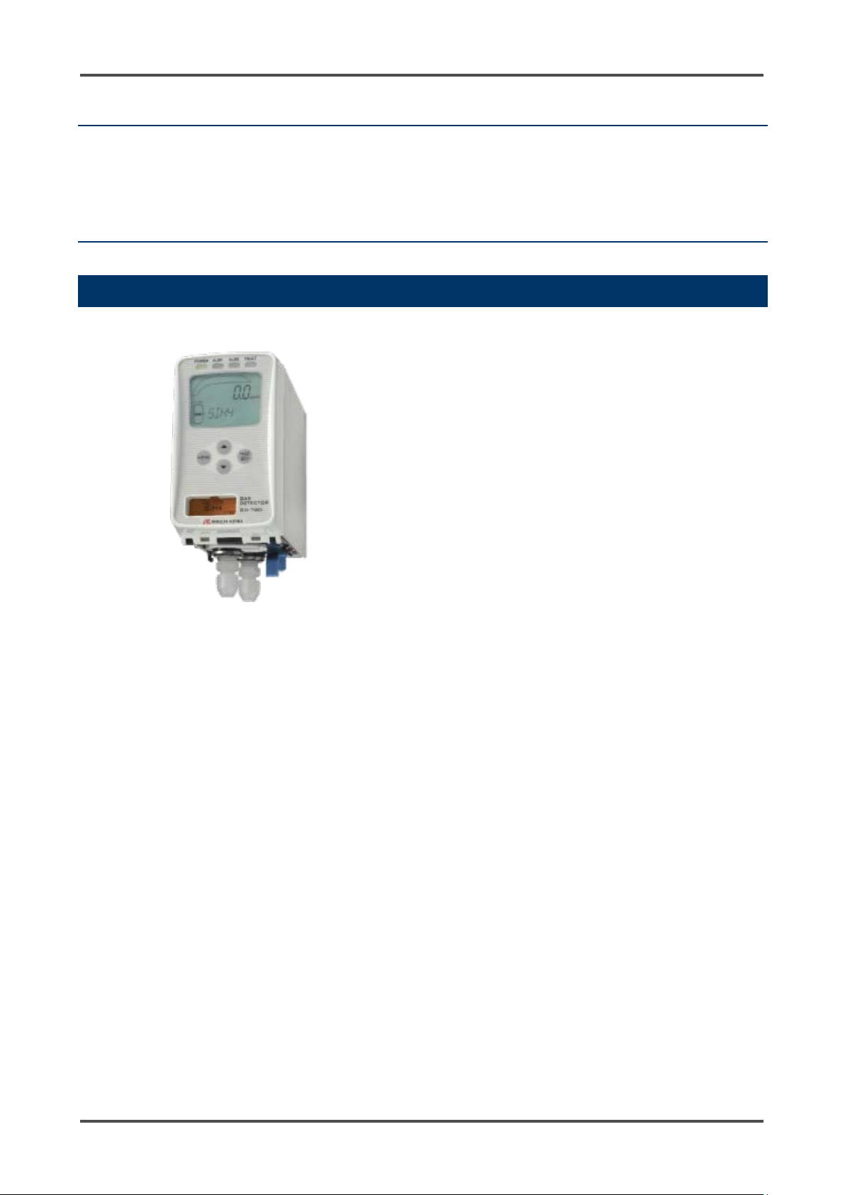
GD-70D
4 - 20 mA specification
Analog transmission
GD-70D-NT
NT specification
2-wire type DC power-line communication
GD-70D-EA
EA specification
Ethernet and analog transmission (4 - 20 mA)
GD-70D-LN
LN specification
LONWORKS
1
Outline of the Product
1-1 Preface
Thank you for choosing our GD-70D Series gas detector head. Please verify that the model number of the
product you purchased is included in the specifications on this manual.
This manual explains how to use the detector and its specifications. It contains information required for
using the detector properly. All users must read and understand the operating manual before using the
detector.
1-2 Product Purpose
• This is a fixed type gas detector head which detects gas leaks in semiconductor factories, etc.
• The gas detector is a safety device, not an analyzer or densitometer which performs quantitative/qualitative
analysis/measurement for gases. You must understand the features of the detector before using it, so that
you can use it properly.
• The detector detects abnormalities in the air caused by the presence of gas (or oxygen deficiency) with the
built-in gas sensor unit. The concentrations of detected gases are shown on the LCD .
• The built-in pump in the detector draws gas to perfo rm gas detect ion.
• The detector has two-step gas alarm conta ct an d fau lt ala r m co nta ct.
• The detector outputs the gas concentration in 4 - 20 mA or digital data.
• The communication method for each specification is as follows.
GD-70D - 4 -
Page 5
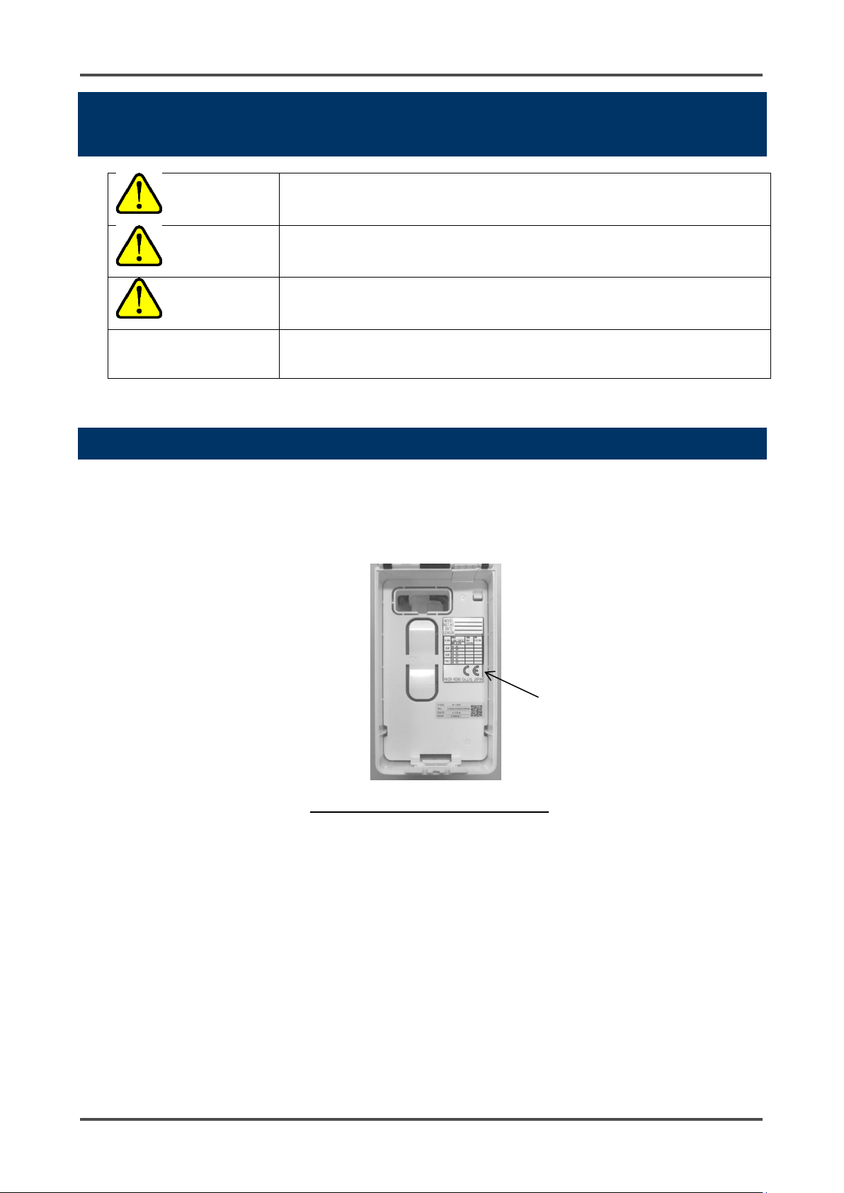
CE Marking
1-3 Definition of DANGER, WARNING, CAUTION and NOTE
This message indicat es that im proper hand ling may ca use serious d amage
DANGER
WARNING
CAUTION
on life, health or assets.
This message indicat es that im proper hand ling ma y cause serious d amage
on health or assets.
This message indicates that improper handling may cause minor damage on
health or assets.
NOTE
This message indicates advice on handling.
1-4 Method of confirmation for CE marking type
The CE marking is labeled on the detector in case of comply with CE marking. Please confirm the
instrument specification before using. Please refer to the Declaration of Conformity that is at the end of this
manual if you have CE marking type.
You can confirm instrument specification to see the CE marking as follows.
CE marking label (Back of front cover)
- 5 - GD-70D
Page 6
Power Supply
2
Important Notices on S afety
2-1 Danger Statements
DANGER
This is not an explosion-proof device. You must not use it to detect gases exceeding the lower limit of explosion.
2-2 Warning Statements
WARNING
Before turning on the detector, always check whether the voltage is properly applied. Do not use an unstable
power supply because it may cause malfunction s.
Need of grounding circuit
Do not cut the grounding circuit or disconnect the wire from the grounding terminal.
Defects in protective functions
Before starting the detector, check the protective functions for defects. When defects are found in the protective
functions, such as protective grounding, do not start the detector.
External connection
Before connecting the detector to external equipment or an external control circuit, securely connect it to a
protective grounding circuit.
Tubing
The detector is designed to draw gases around it under normal atmospheric pressure. If excessive pressure is
applied to the sampling inlet and outlet (GAS IN, GAS OUT) of the detector, detected gases may leak from the
flow system and pose dangers. Be sure that excessive pressure is not applied to the detector when it is used.
Detected gases must be exhausted from the outlet (GAS OUT) on the bottom of the detector to a safe place
using an exhaust tube.
Handling the sensor unit
Do not disassemble the electrochemical type sensor unit (ESU) or galvanic cell type sensor unit (OSU) because
they contain electrolyte. Electrolyte may cause severe skin burns if it contacts skin and may cause blindness if it
contacts eyes. It may discolor or damage clothing. If contact occurs, ri nse the area immediately with a large
quantity of water.
Zero adjustment (AIR Adjustment) in the atmosphere
When zero adjustment (AIR Adjustment for oxygen deficiency alarm) is performed in the atmosphere, check the
atmosphere for freshness before beginning the adjustment. If other gases exist, the adjustment cannot be
performed properly and the detector will not properly detect gas.
Operation in a gas
Do not operate the detector in a place where flammable/explosive gases or vapors are present. Operating the
detector in such an environment will lead to extreme dangers.
Response to a gas alarm
Issuance of a gas alarm indicates that there are extreme dangers. Take proper actions based on your judgment.
GD-70D - 6 -
Page 7
Definition of Terms
Do not use a transceiver (walkie-talkie) near the detector.
2-3 Caution Statements
CAUTION
Radio waves from a transceiver near the detector or its cables may disrupt detector operation. When using a
transceiver, it must be used in a place where it disturbs nothing.
Do not turn the detector on less than 5 seconds after it was turned off.
Restarting the detector less than five second s after turning it off may cause errors.
Verify that the reading on the flow rate indicator corresponds to the specified flow rate before using the
detector.
If it does not correspond to the specified flow rate, gas detection cannot be performed properly. Be sure the flow
rate is stable.
Attach the dust filter before using the detector.
Before using the detector, attach the specified filter to prevent disturbances by possible gas absorption or air
dust.
The dust filter used depends on the gas being detected. For more information on dust filters, please contact RKI.
Observe the operating restrictions to prevent condensation inside the tube.
Condensation formed inside the tube causes clogging or gas absor ptio n, w hich di sturb s acc urate gas detection.
Thus, condensation must be avoided. In addition to the installation environment, carefully monitor the
temperature/humidity of the sampled area to prevent condensation inside the tube. In particular, when detecting
a corrosive, water-soluble gas, such as a strong acid gas, the gas is undetectable and furthermore may corrode
internal parts. Please observe the operating restrictions.
Do not use the external output of the detector to control other devices.
This is not a control device. You are not allowed to use its external output to control other devices.
Do not disassemble/modify the detector, or change the settings unless necessary.
Disassembling/modifying the detector will invalidate the guarantee of the performance. Changing the settings
without understanding the specifications may cause alarm malfunctions. Please use the detector properly in
accordance with the operating manual.
Do not forget to perform regular maintenance.
Since this is a safety device, regular maintenance must be performed to ensure its safety. Continuing to use the
detector without performing maintenance will compromise the sensitivity of the sensor, thus resulting in
inaccurate gas detection.
- 7 - GD-70D
Page 8
<Standard Accessories>
3
Product Components
3-1 Main Unit and Standard Accessories
<Main Unit>
• Operating manual
• Protective rubber cap (to be removed when using the
detector)
• Dedicated handling lever (for wiring)
• Dust filter
• Interference gas removal filter
(to be supplied with sensor units for certain gases)
GD-70D - 8 -
Page 9
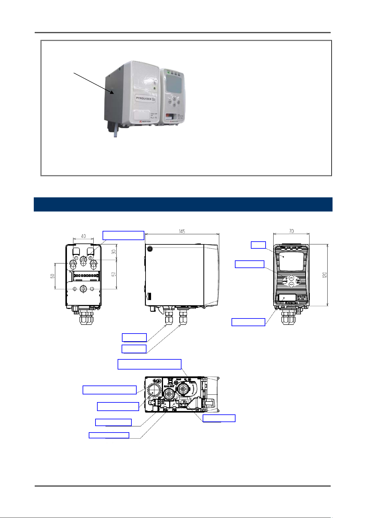
Pyro lyzer Uni t
(Unit: mm)
GAS IN
GAS OUT
Sensor unit display
Operating switch
Screw for grounding earth rod
External wire hole
Power switch
<Pyrolyzer Unit (PLU-70)(Option)>
* This is needed in “pyrolyzer + electrochemical type (ESU)” and “pyrolyzer + pyrolysis-particle type
(SSU)”.
For more information on the pyrolyzer unit (PLU-70), see the separate operating manual.
3-2 Outline Drawing
M5 mounting hole
Display
Protective cover for power switch
Connector for PLU
Connector for PoE
- 9 - GD-70D
Page 10
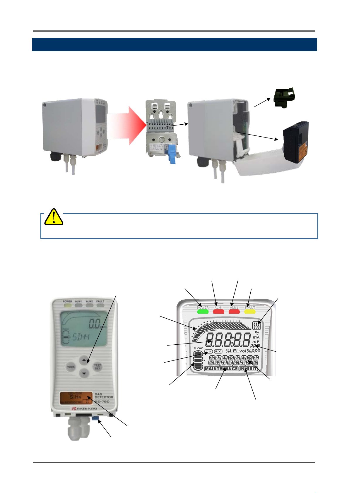
Wall-mounted unit
Main unit
Pump unit
Sensor unit
MODE key
Lock lever
Sensor unit nameplate display window
Power lamp
First alarm lamp
Second alarm lamp
Fault lamp
⑪
⑫
⑬
⑭
bar indicator
⑮
⑯
indicator
⑰
⑱
indicator
⑲
⑳
connection indicator
CAUTION
the unit compromises its original performance or causes malfunctions.
3-3 Names and Functions for Each Part
The detector consists of the following units.
Each unit consists of precision parts. When a unit is detached, be careful not to drop it. Dropping
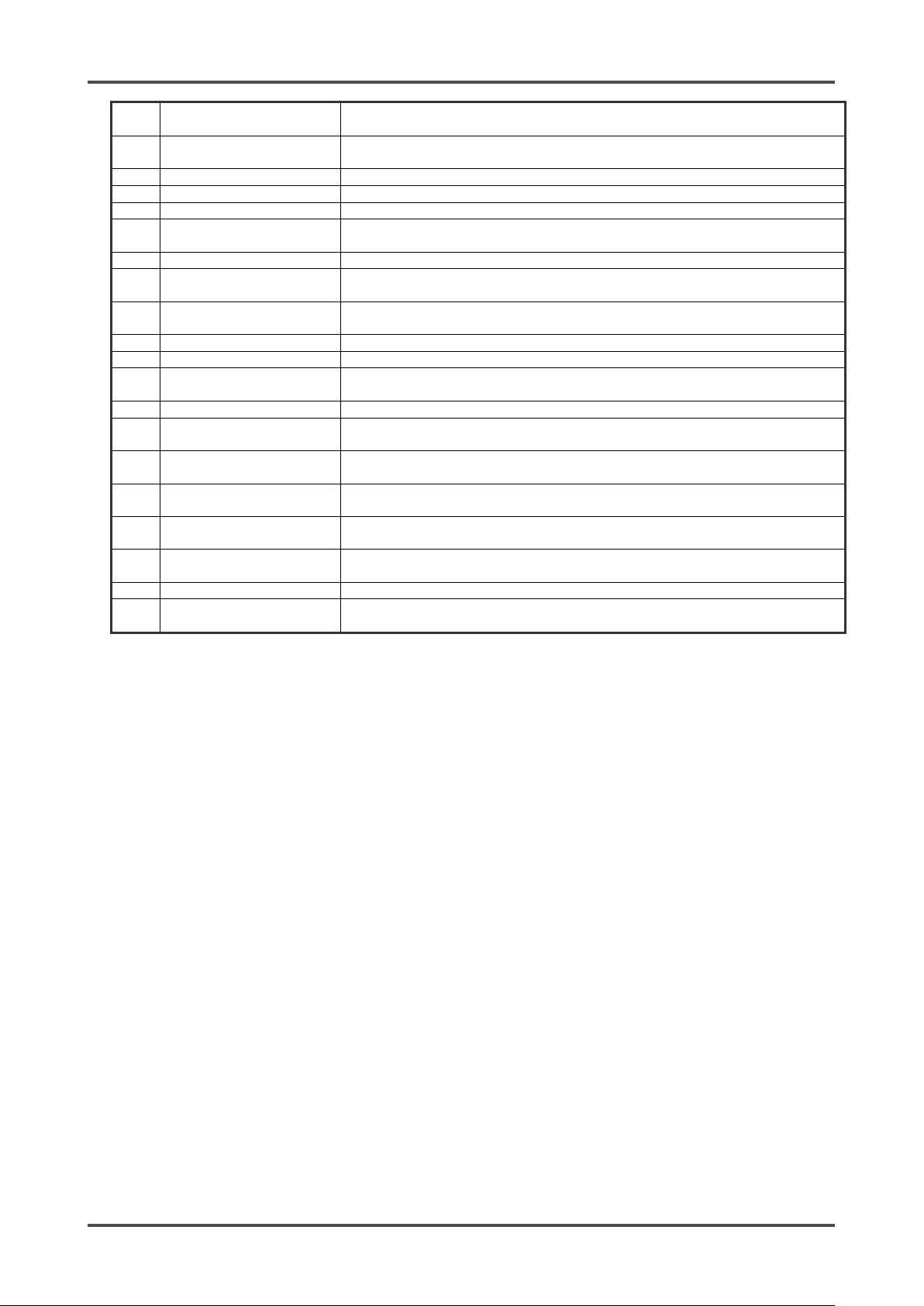
<Front Panel and Character LCD>
TEST/SET key
▲key
▼key
Concentration
Alarm setpoint
indicator
Concentration
value display
Communication
indicator
Flow rate
Maintenance
Pyrolyzer unit
Unit display
Gas name display
Inhibit indicator
GD-70D - 10 -
Page 11
MODE key
Used to enter User and Maintenance Mode.
It is also used to cancel or skip in a specific mode.
TEST/SET key
Used to enter the test mode.
It is used for confirmation in a specific mode.
▲ key
Used to change screens or change a value (UP).
▼ key
Used to change screens or change a value (DOWN).
Lock lever
Lever to lock the main unit. Push it to attach or detach the main unit.
Sensor unit nameplate
display window
Window to view information on the currently installed sensor.
Power lamp (POWER)
Power lamp. Turns green when the power is on.
First alarm lamp
(ALM1)
First alarm lamp. Turns red when the first alarm is reached.
Second alarm lamp
(ALM2)
Second alarm lamp. Turns red when the second alarm is reached.
Fault lamp (FAULT)
Fault lamp. Turns yellow when an abnormality is detected in the detector.
Gas name display
Displays the gas name in chemical formu la (e.g. Silane = SIH4).
Concentration value
display
Displays the gas concentration.
Unit display
Displays the unit according to the specification (ppm, ppb, vol%, %, %LEL).
Concentration bar
indicator
The detectable range (full scale = FS) is divided into 20 segments. The
increase in concentration is displayed in prop ortio n to the full scale.
Alarm setpoint
indicator
The alarm setpoints (AL1 and AL2) are indicated on the conc entr at ion bar.
Flow rate indicator
Displays the flow rate. When the line is in the middle of the indicator, t he
flow rate is normal (0.5 L/m in).
Communication
indicator
For GD-70D-NT, this indicator is displayed while transmitting data with the
upper unit (TX, RX).
Maintenance indicator
Displayed while in Maintenance Mode. When this indicator is displayed, the
alarm contact is disconnected and there are no alarms.
Inhibit indicator
Displayed when the inhibition (point skip) is set.
Pyrolyzer unit
connection indicator
Displayed when the dedicated pyrolyzer unit (PLU-70) is connected.
①
②
③
④
⑤
⑥
⑦
⑧
⑨
⑩
⑪
⑫
⑬
⑭
⑮
⑯
⑰
⑱
⑲
⑳
<Main Unit>
The main unit of the GD-70D houses the sensor unit, pump unit,
and circuitry for the detector. The main unit installs to the
mounting plate’s terminal plate.
<Pump Unit>
The pump unit gets installed in the main unit. It draws sample into the detector at 0.5 L/min.
- 11 - GD-70D
Page 12
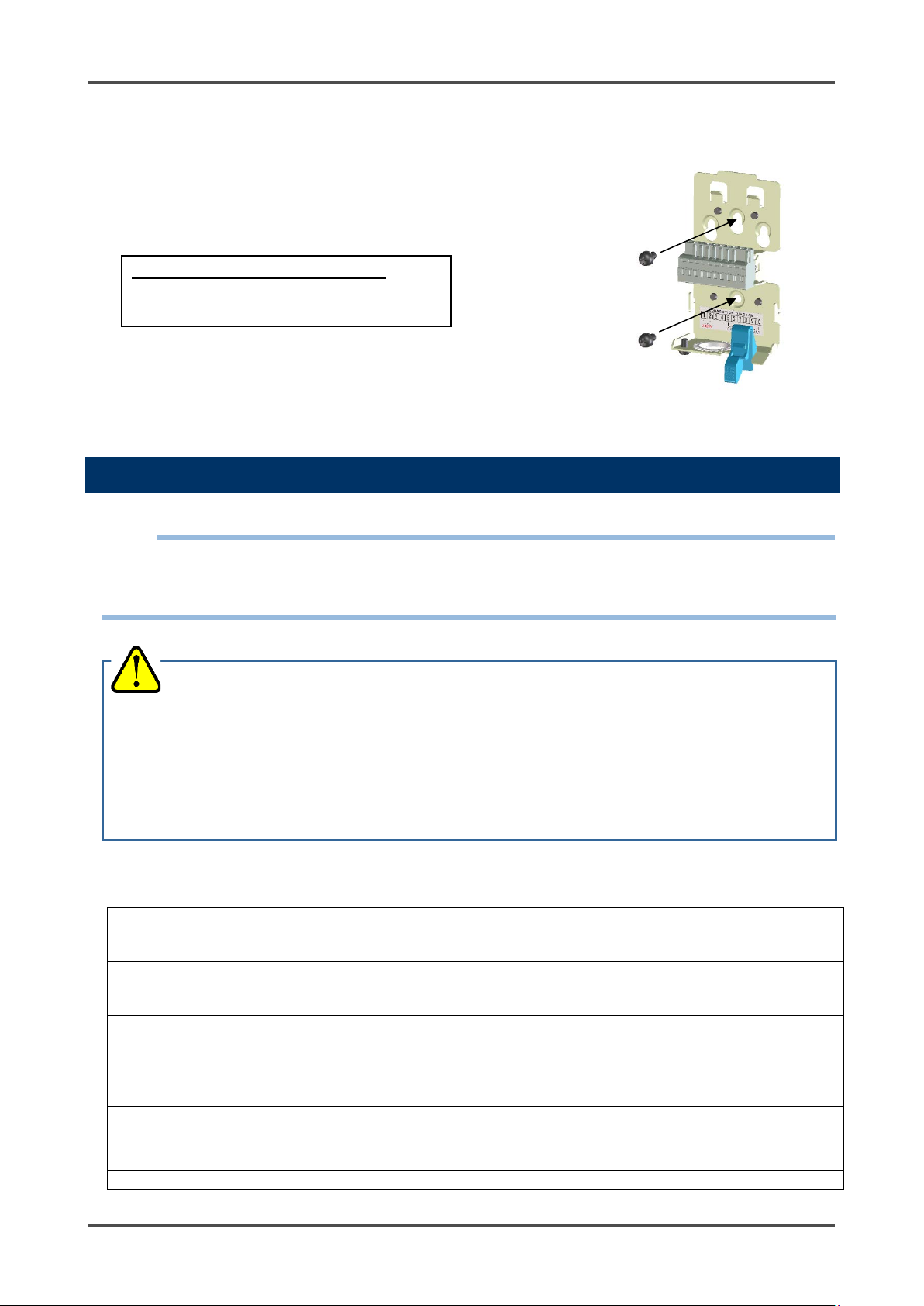
adjustment).
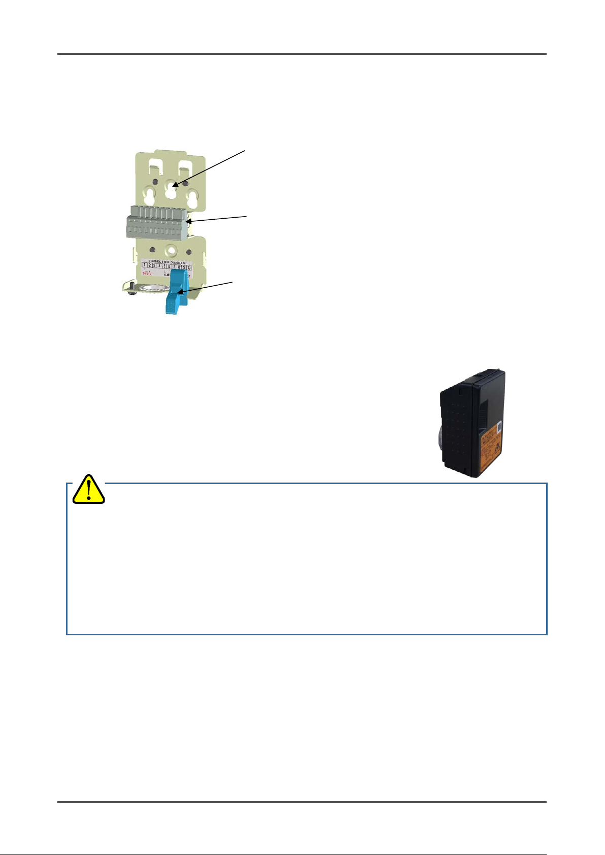
Mounting hole
10-point terminal plate: Connections for power supply,
signal cables and other external wires.
Locking lever: Locks the main unit to the mounting plate.
<Mounting Plate>
The mounting plate gets installed to the installation site. The main unit connects to the mounting plate
using the 10-point terminal plate.
<Sensor Unit>
A sensor unit installed in the detector is the same regardless of
the detection principle which means sensor units are
interchangeable. Each sensor unit has a different color that
corresponds to the detection principle as shown below. Handling
of the sensor unit depends on the detection principle.
CAUTION
• The sensor unit must be handled carefully to ensure quality. When the sensor unit is stored, a
dedicated warehouse and power equipment for the sensor unit are needed. In principal, the sensor
unit must not be detached from the detector when it is handled or stored.
• Be sure that the sensor unit is installed properly.
If a sensor unit is of different specification or principle than the one shipped from the manufacturer, a
message will be display ed on the dete ctor LCD (C-02).
If this message is displayed, make sure you are using the correct sensor unit.
• After the sensor unit is replaced, always perform a gas calibration (zero adjustment and span
GD-70D - 12 -
Page 13
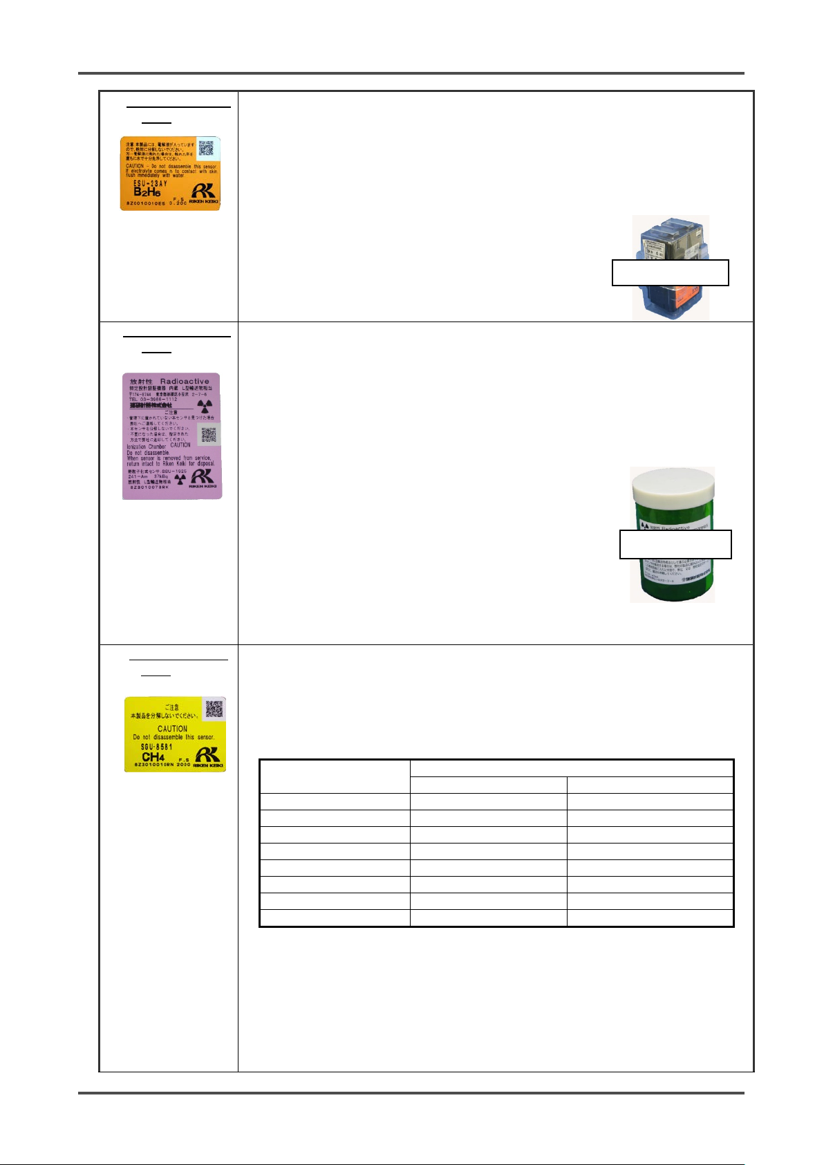
Electrochemical
• Do not disassemble the sensor unit because it contains electrolyte. If contact
Pyrolysis-particle
• Although the sensor unit contains radioactive materials, it is certified as a
Semiconductor
• Before using the sensor unit, it needs to be warmed up for a specified time.
Unpowered time
Suggested warm-up time
SGU-8541 (H2)
SGU (Others)
10 minutes or less
10 minutes or more
2 hours or more
1 hour or less
30 minutes or more
2 hours or more
24 hours or less
1 hour or more
4 hours or more
72 hours or less
4 hours or more
24 hours or more
10 days or less
2 days or more
2 days or more
Less than 1 month
7 days or more
7 days or more
Less than 3 months
14 days or more
14 days or more
3 months or more
1 month or more
1 month or more
Dedicated case
Dedicated case
type (ESU)
type (SSU)
occurs, rinse the area immediately with a large quantity of water.
• The sensor unit identifies the storage direction. Put the sensor unit in the
dedicated case while handling it. Do not place it on its side or upside-down.
• When a new sensor unit is installed, it must be warmed up.
Although warm-up time is different depending on the type of the installed
sensor, it is recommended that warm-up should be performed for three hours or
more. Please contact RKI for more information.
• The sensor unit must be stored in a clean, cool and
dark place away from direct sunlight. Some types of
the sensor units cannot be stored together with other
units. Please contact RKI for more information.
specified designing certification device, which is regarded as a device
having no influences on health. Observe the "Safety Manual" which
stipulates conditions for the certification. To dispose of the sensor unit, you
must return it to us. You do not need to take any additional actions.
• The sensor unit contains a small amount of radioactive materials. Do not
disassemble it, or dispose of it like other wastes.
• The sensor unit must be put into the dedicated case specified by us, and
stored away from direct sunlight in a clean place
where the temperature and humidity are maintained
at a normal level and where appropriate measures
are taken to prevent the sensor from being taken out
easily.
• When the sensor unit is transported out of your
factory, please use a transportation company which
can handle specified designing certification devices
(L-type packages).
• For more information, see the "Safety Manual".
type (SGU)
The sensor unit is warmed up sufficiently in our factory before it is delivered to
you. Therefore, after you receive the sensor unit, please use it as soon as
possible so that unpowered time is minimized.
• The warm-up time before using the sensor unit is related to how long the
sensor unit was unpowered .
• To store the sensor unit in an unpowered state, it must be stored under
normal temperature/humidity in a clean place away from direct sunlight.
- 13 - GD-70D
Page 14

Galvanic cell type
• Do not disassemble the sensor unit because it contains electrolyte. If contact
Sensor unit
Flow
Pump
POWER INPUT (24
VDC)
Power supply part
Gas alarm contact
Alarm contact controller
Transmitter
EA specification)
Amplifier
Controller
Display
Operating unit
4 - 20 mA specification:
(OSU)
occurs, rinse the area immediately with a large quantity of water.
• The sensor unit must be stored under normal tem per atur e/humidity in a clean
place away from direct sunlight.
3-4 Operation Diagrams
<Electric Diagram>
(ALM1, ALM2)
Fault alarm contact
(FAULT)
* Standard setting of
GD-70D - 14 -
contact activation
De-energized
(De-energized at a
normal state)
ON-ALARM
(Closed contact at
an alarm state)
(4 - 20 mA/NT/
4 - 20 mA DC transmission
NT specification: Digital
data transmission
EA specification: Ether net
and 4-20 mA DC
transmission
LN specification: confirm to
LONWORKS
Controller
(CPU)
(CPU)
(POWER) (ALM1) (ALM2)
(FAULT)
LCD
(MODE) (▲) (▼) (TEST/SET)
Pump
control
circuit
sensor
Page 15
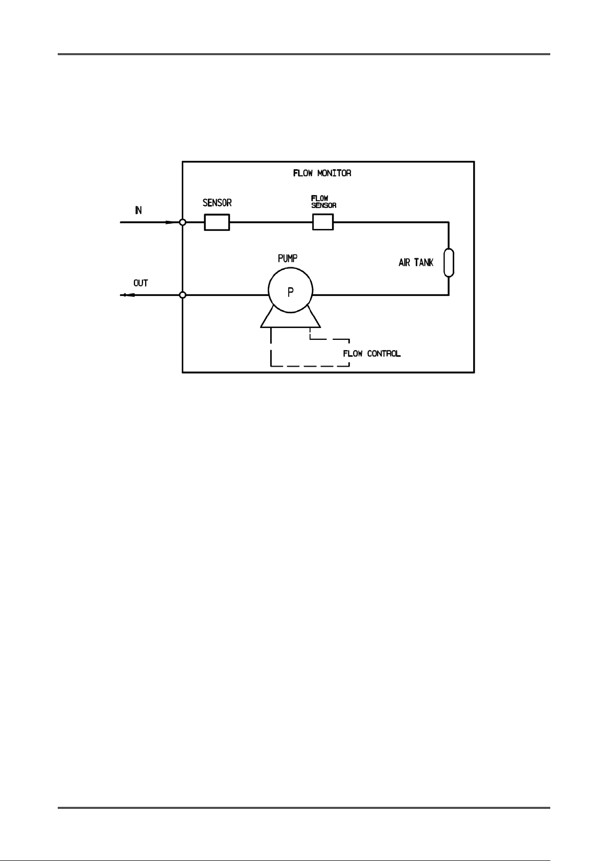
<Tubing Diagram>
- 15 - GD-70D
Page 16
working areas, carefully consider how many units to install and whe re to in stall t he m.
sensor unit.
4
Installation
4-1 Requirements
All users must follow the operating precautions. Ignoring the precautions may damage the detector,
resulting in inaccurate gas detection.
CAUTION
• After you receive the detector, start using the detector within the specified operation start limit of the
4-2 Precautions for installation sites
CAUTION
• This is a precision instrument. Because the detector may not provide the specified performance in
some places (environments), check the environment in the installation site, and then take
appropriate actions if necessary.
• Because the detector plays an important role for safety and disaster prevention, you must install as
many units o f the det e ctor a s nee ded in a pp ropri at e p oin ts.
• Because gases may leak or collect in different areas depending on the types of gases and the
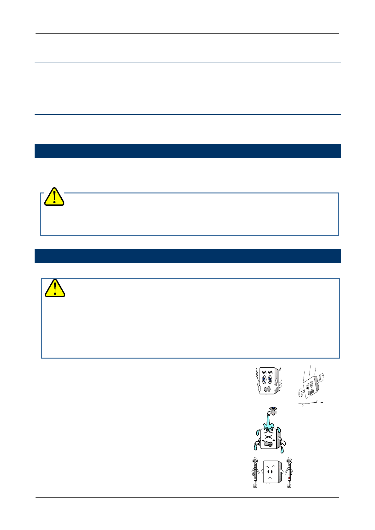
Do not install the detector in a place with
vibrations or shocks.
The detector contains sensitive electronic parts. The detector
must be installed in a stable place without vibrations or shocks
and where it will not fall.
Do not install the detector in a place exposed to
water, oil or chemicals.
Avoid installation locations where the detector is exposed to
water, oil or chemicals.
Do not install the detector in a place where the
temperature drops below 0ºC or rises over 40ºC.
The operating temperatures of the detector are 0 - 40ºC. The
detector must be installed in a stable place where the operating
temperatures are maintained and do not change suddenly.
GD-70D - 16 -
Page 17

Do not install the detector in a place exposed to direct
sunlight or sudden changes in the temperature.
Avoid installation locations where the detector is exposed to
direct sunlight or radiant heat (infrared rays emitted from a hightemperature object), and where the temperature changes
suddenly. Condensation may form inside the detector, or the
detector cannot adjust to sudden changes in the temperature.
Keep the detector (and its cables) away from
noise source devices.
Avoid installation locations where high-frequency/high-voltage
exist.
Do not install the detector in a place where maintenance of the detector cannot be
performed or where handling the detector involves dangers.
Regular maintenance of the detector must be performed.
Do not install the detector in a place where the equipment must be stopped when maintenance is
performed, where parts of the equipment must be removed to perform maintenance, or where the detector
cannot be removed because tubes or racks prevent access to it. Do not install the detector in a place
where maintenance involves dangers, for example, near a high-voltage cable.
Do not install the detector in equipment which is not properly grounded.
Before installing the detector in equipment, the equipment must be grounded properly.
Do not install the detector in a place where other gases exist around it.
The detector must not be installed in a place where other gases exist around it.
- 17 - GD-70D
Page 18
Power supply voltage
or PoE connection (GD-70D-
EA)
Allowed time of
Up to 10 milliseconds (To
detector.)
Example of actions
Others
Do not use it with a power
frequency noise.
Example of actions
Protection against
Take appropriate measures in accordance with the importance of the facilities
Grounding
In addition to lightning, there are more sources of surge noise. To protect
devices from these noise sources, the devices must be grounded.
• An unstable power supply and noise may cause malfunctions or false alarms.
4-3 Precautions for System Designing
CAUTION
Using a stable power supply
The external output and alarm contact of the detector may be activated when the power is turned on, when
momentary blackout occurs, or when the system is being stabilized. In such cases, use a safety power
supply, or take appropriate actions on the receiving side.
The detector must be provided with the following power supply.
24 VDC ±10% (the terminal voltage of the detector)
momentary blackout
recover from a momentary
blackout longer than 10
milliseconds, restart the
supply that has a large
power load or high-
To ensure continuous operation and activation, install
a protective power supply outside the detector.
Use a line filter to avoid the noise source if
necessary.
Heat radiation designing
When it is installed in the closed instrumentation board, attach ventilation fans above and below the board.
Protecting against lightning
If cables are installed outside the factory/plant, or if internal cables are installed in the same duct as the
cables coming from outside the factory/plant, lightning will cause problems. Because lightning acts as a
large emission source while cables act as a receiving antenna, devices connected to the cables may be
damaged.
Lightning cannot be prevented. Cables installed in a metal conduit or under the ground cannot be
completely protected from a power surge caused by lightning. Although complete elimination of disasters
caused by lightning is impossible, the following protective measures can be taken.
lightning
and the environment.
• Connect the transmissi on sign al rout e by using optical fiber.
• Provide protection by a lightning arrester (cable safety retainer).
(Although indu ctiv e l igh tni ng su r ge can be t ran smi tted th ro ugh t he c abl e, it
is prevented by i n stalli n g a l ig htn ing a rre ste r be fo re t he fiel d dev i ces a nd
central processing equipment. For information on how to use a lightning
arrester, please contact the manufacturer.)
* The lightning arrester has a circuit to remove a surge voltage which damages field devices, so that
signals may be attenuated. Before installing a lightning arrester, verify that it works properly.
GD-70D - 18 -
Page 19
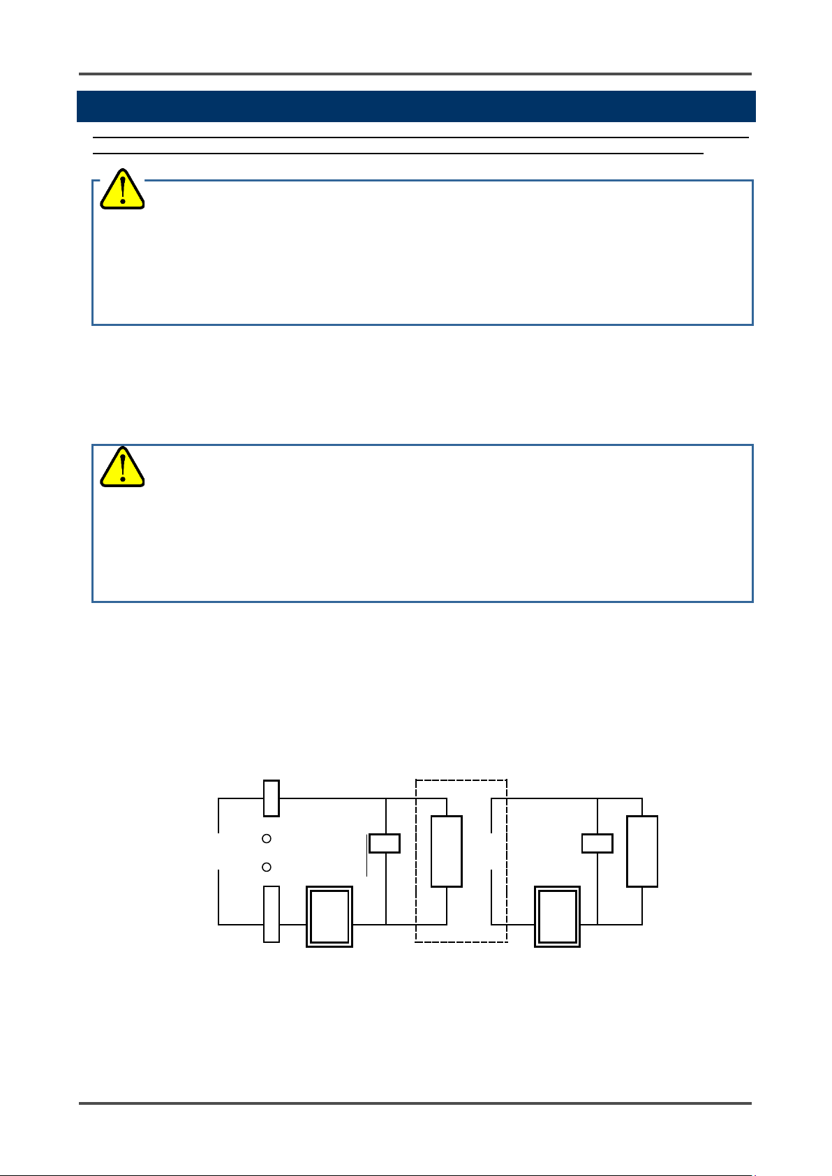
GD-70D
SK1
SK2
Alarm
Contact
Power
Power
External relay
(low voltage relay)
* SK1, SK2: Surge absorbing parts
receiving side of the b cont act.
as a CR circuit.
4-4 Proper use of alarm contact
The alarm contact of the detector is used to transmit signals to activate an external buzzer, alarm lamp or
rotating lamp. Do not use the detector for controlling purpose (e.g., controlling the shutdown valve).
CAUTION
• The b contact (break contact) under de-energized state may be open ed momen ta rily by a physical
shock, such as external force.
• When the b contact is selected for the alarm contact, take appropriate actions to prepare for a
momentary activation by adding signal delay functionality (approximately one second) to the
The specifications for the alarm contact of the detector are based on the resistive load conditions. If
inductive load is used at the alarm contact, the following errors will occur easily because counter
electromotive force is generated at the contact.
• Deposition, defective insulation or defective contact at the relay contact
• Damage of any el e ctri c pa r ts due t o hi gh-voltage generated inside the detector
• Abnormal operations by an out-of-control CPU
CAUTION
• In principal, do not activate inductive load at the alarm contact of the detector. (In particular, never
use the inductive load to activate a fluorescent lamp or motor.)
• If inductive load is activated, relay it with an e xternal relay (c ontact amplifi cation). However, because
the coil of a n e xte rnal relay al so inv olv e s in du ctiv e l oad , sele ct a relay a t a low e r v ol tag e (1 00 VAC o r
below), and then p r otec t the c o ntac t of t he de te cto r wi th an ap p rop riat e sur ge ab sorbi ng pa r t, su ch
If load is to be activated, appropriate measures must be taken to stabilize the operation of the detector and
protect the alarm contact referring to the following information.
• Relay it with a n e x tern al rel ay at 100 VAC or lower (contact amplification). At the same time, the surge
absorbing part, SK1, suitable for the specifications must be attached to the external relay.
• In addition, the surge absorbin g part, SK2, must be attach ed to the loa ded side of the e xternal relay if
necessary.
• It may be recommended that the surge absorbing part be attached to the contact for certain load
conditions. It must be a ttac he d to an ap pr op riate po si ti on by che ckin g how t he loa d is activated.
Coil
Load
supply
- 19 - GD-70D
supply
Page 20

be damaged. Do not forget to remove the caps.
Leave space for the crosshatched area when installing the detector.
resonance between them. In this case, take preventive actions like reinforcing the rack or wall.
Maintenance space
Maintenance space
Maintenance space
Maintenance space
Maintenance space
Maintenance space
When installing using 2 screws
When installing using 3 screws
(Unit: mm)
(300)
(90)
(300)
4-5 Installing the Detector
NOTE
To use the pyrolyzer unit (PLU-70), also refer to the individual operating manual.
CAUTION
• Before installing the detector, remove the protective rubber caps from the GAS IN and GAS OUT
fittings. If the detector is turned on while the rubber caps are still in place, the pump and sensor may
<Detector Dimensions and Maintenance Space>
CAUTION
• Multiple detectors installed in the same location must be installed at least 5 mm apart. It is
recommended that they be 10mm apart.
• When you install more than one detector in the same location, install them in a rack or on a wall that
is not affected by vibrations.
When the detectors are installed side-by-side, if the rack or wall in which the detectors are installed
does not have enough streng th, vibrations from the pumps inside the detectors can cause
The crosshatched space represents necessary maintenance space.
GD-70D - 20 -
Page 21
Wall
Floor
Ceiling
Wall
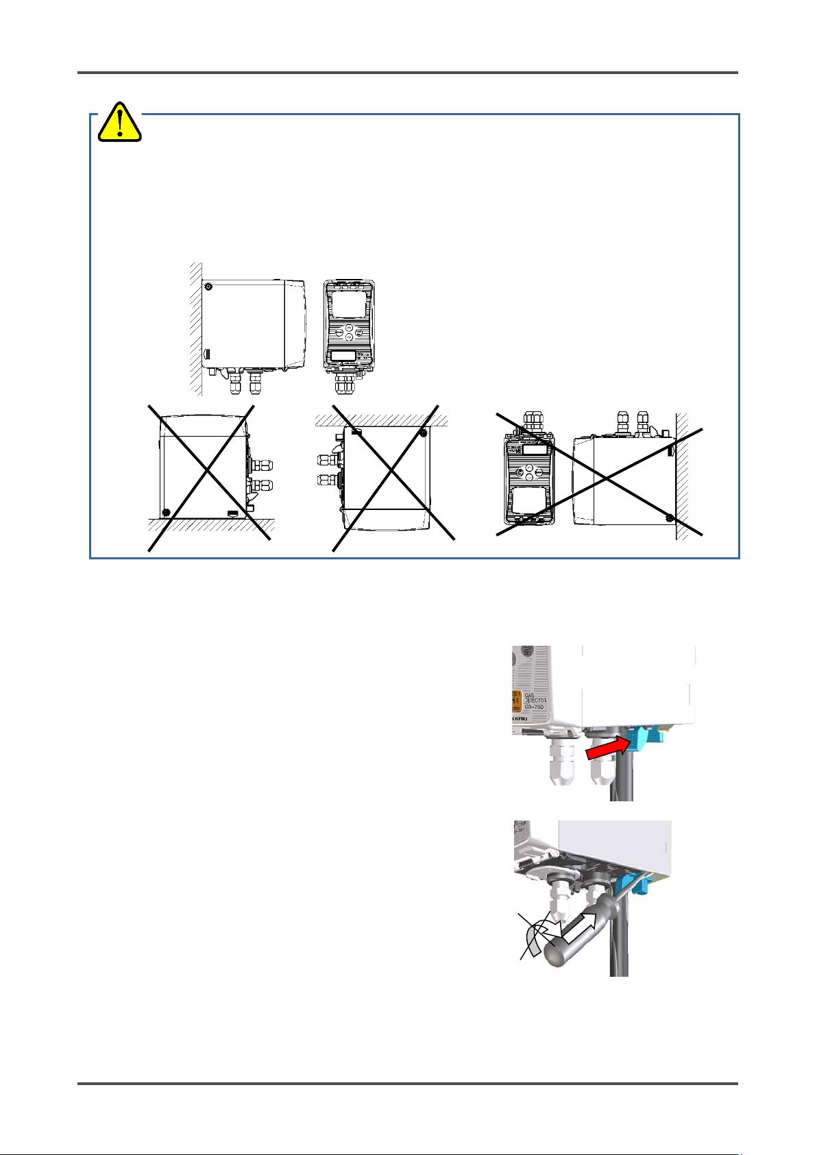
CAUTION
• The detector must be installed in the correct orientation to ensure its performance. Install the
detector as shown on the follow ing ex ample. (* The dete ctor must al so remain in this orie ntati on
during transportation.)
<Correct Installation Orientation>
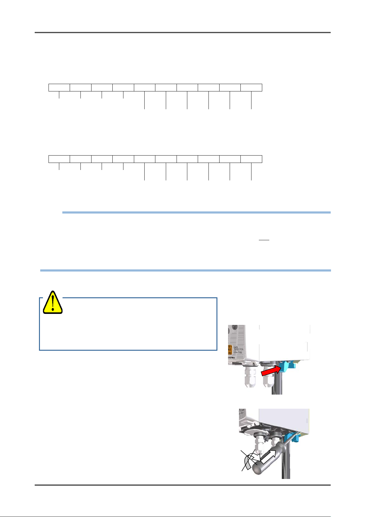
<Installing the Mounting Plate>
1. Make sure power to the detector is turned off.
2. While pushing the blue lever toward the mounting plate,
push the main unit up.
3. If you cannot move the main unit, insert a larger flathead
screwdriver into the mounting plate while pushing the lever
as shown to the right. Do not rotate or move the flathead
screwdriver. Simply insert it into the mounting plate.
4. Remove the silver mounting plate from the back of the GD-70D.
- 21 - GD-70D
Page 22
For 3-wire type (common cable for
specification)
Shielded cable of CVVS, etc. (1.25 mm2) - 3-core
For 2-wire type (power and signal
specification)
Power: Cable of CVV, etc. (1.25 mm2) - 2-core
For 2-wire type DC power-line
specification)
Shielded twisted-pair cable of KPEV-S, etc. (1.25 mm2) For Ethernet (EA)
Power: Cable of CVV, etc. (1.25 mm2) - 2-core
Signal: Ethernet cable (category 5 or higher)
For PoE (EA)
Ethernet cable (category 5 or higher)
For LONWORKS output cable
・
1P
For contact
Cable of CVV, etc. (1.25mm2) - max. 6-core
• When stranded wires are used, prevent wires from contacting each other.
5. Attach the mounting plate to the installation surface using two or three M5 screws.
Recommended mounting screw (M5)
Length of 8 mm or more
Flat washer of φ10 mm or less (small round)
6. Leave the main unit detached from the mounting plate and continue to the wiring section.
4-6 Wiring the Detector
NOTE
To use the pyrolyzer unit (PLU-70), also refer to the separate operating manual.
CAUTION
• Be careful not to damage the in te rnal ele ct roni c cir cuit w h en w i ring. I n a ddi tio n, be care ful t o p rovi de
appropriate strain relie f w hen u si ng cabl e s for w i ring.
• The power cables and signal cables must not be installed together with the motor power cables, etc.
When these cables must be installed together for unavoidable reasons, put the power cables and
signal cables in a metal conduit. The conduit must be connected to a groundin g circuit .
<Recommended Cable>
power and signal) (4 - 20 mA/EA
cables separated) (4 - 20 mA/EA
Signal: Shielded cable of CVVS, etc. (1.25 mm2) - 2-core
communication system (NT
GD-70D - 22 -
1P
Shielded twisted pair cable of KPEV-S, etc. (1.25 mm2)
Page 23
Dedicated
handling lever
Wiring hole
Driver slot
Conductive
part
Cage
Top handling slot
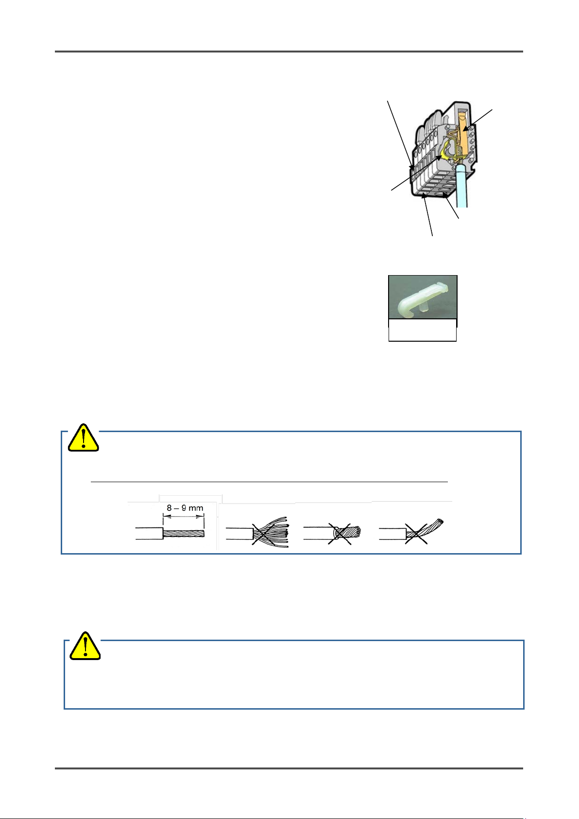
<Terminal Plate Specifications>
Specifications of terminal plate
• Rated voltage: 250 VDC
• Rated current: 16 A
Connection conditions
• Cable: 0.08 - 2.5mm2
• Bare wire length: 8 - 9 mm
• Connecting tool: Dedicated handling lever (accessory)
CAUTION
• The specified bare wire length must be observed when the wire insulation is peeled off.
• Be careful not to separate the wire strands.
Compatible bar terminal
For a bar terminal, the following items are available.
• Bar terminal (ferrule): Model 216 Series (manufactured by WAGO)
clamp/spring
• Crimping tool: Model VarioCrimp 4 (206-204) (manufactured by WAGO)
CAUTION
• A bar terminal of the specified model must be used. Using other bar terminals invalidates the
guarantee of the performance.
- 23 - GD-70D
Page 24
1 2 3 4 5 6 7 8 9
10
+
-
+
-
24 VDC
4 - 20 mA
ALM1
contact
ALM2
contact
FAULT
contact
1 2 3 4 5 6 7 8 9
10
+
-
+
-
24 VDC
LONWORKS
output
ALM1
contact
ALM2
contact
FAULT
contact
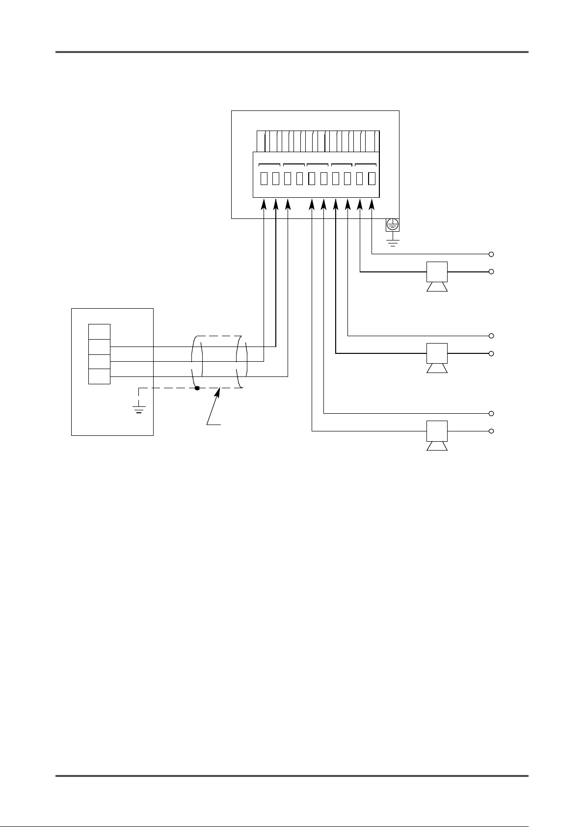
<Wiring to the Terminal Plate>
● 4 - 20 mA/NT/EA Specification
●LN Specification
NOTE
For a 3-wire type 4 - 20 mA, terminal 2 is used as common for the power supply and the 4-20 mA output.
Therefore, wiring should be connected to terminals 1, 2, and 3 only. Terminal 4 can be left open.
For the NT specification, terminals 3 and 4 are not used.
For the EA specification with PoE connection, terminals 1 and 2 are disabled.
CAUTION
• The right tools must be used.
• Only one wire can be connec t ed to e a ch wi rin g hole .
• Do not connect a wire anywhere othe r than a wi ring hole.
1. Make sure power to the detector is turned off.
2. While pushing the blue lever toward the mounting plate,
push the main unit up.
3. If you cannot move the main unit, insert a larger flathead
screwdriver into the mounting plate while pushing the lever
as shown to the right. Do not rotate or move the flathead
screwdriver. Simply insert it into the mounting plate.
GD-70D - 24 -
Page 25
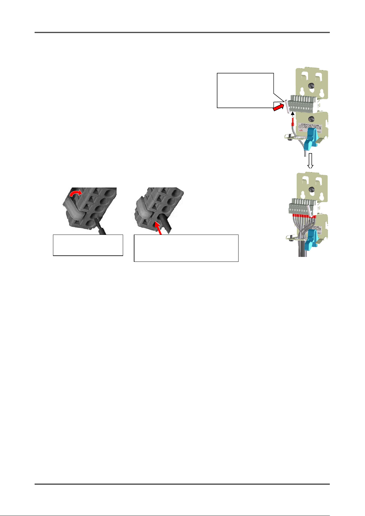
Push the dedicated
Push the lever with your
in its inside.
While holding down the lever, insert the
lever is released, the wire is secured.
4. Use the handling lever included with the GD-70D or a
flathead screwdriver to make wiring connections.
5. Route the wires through the wiring opening in the bottom of
the mounting plate.
6. Insert the handling lever into the driver slot associated with
the terminal you are wiring.
7. Push the lever toward the terminal plate so the protr us ion on
the lever goes into the top handling slot and opens the
wiring hole. If you are not using the handling lever, push
down into the top handling slot with a flathead screwdriver.
8. Hold the lever down while you insert a wire into the wir i ng
hole.
9. Release the lever. Gently pull on the inserted wire to make
sure it is connected.
10. Repeat for all other wiring connections.
finger to lower the spring
wire into the (round) wiring hole until it
reaches the deepest point. Once the
handling lever to
open the terminals.
Insert 1 wire per
terminal.
- 25 - GD-70D
Page 26
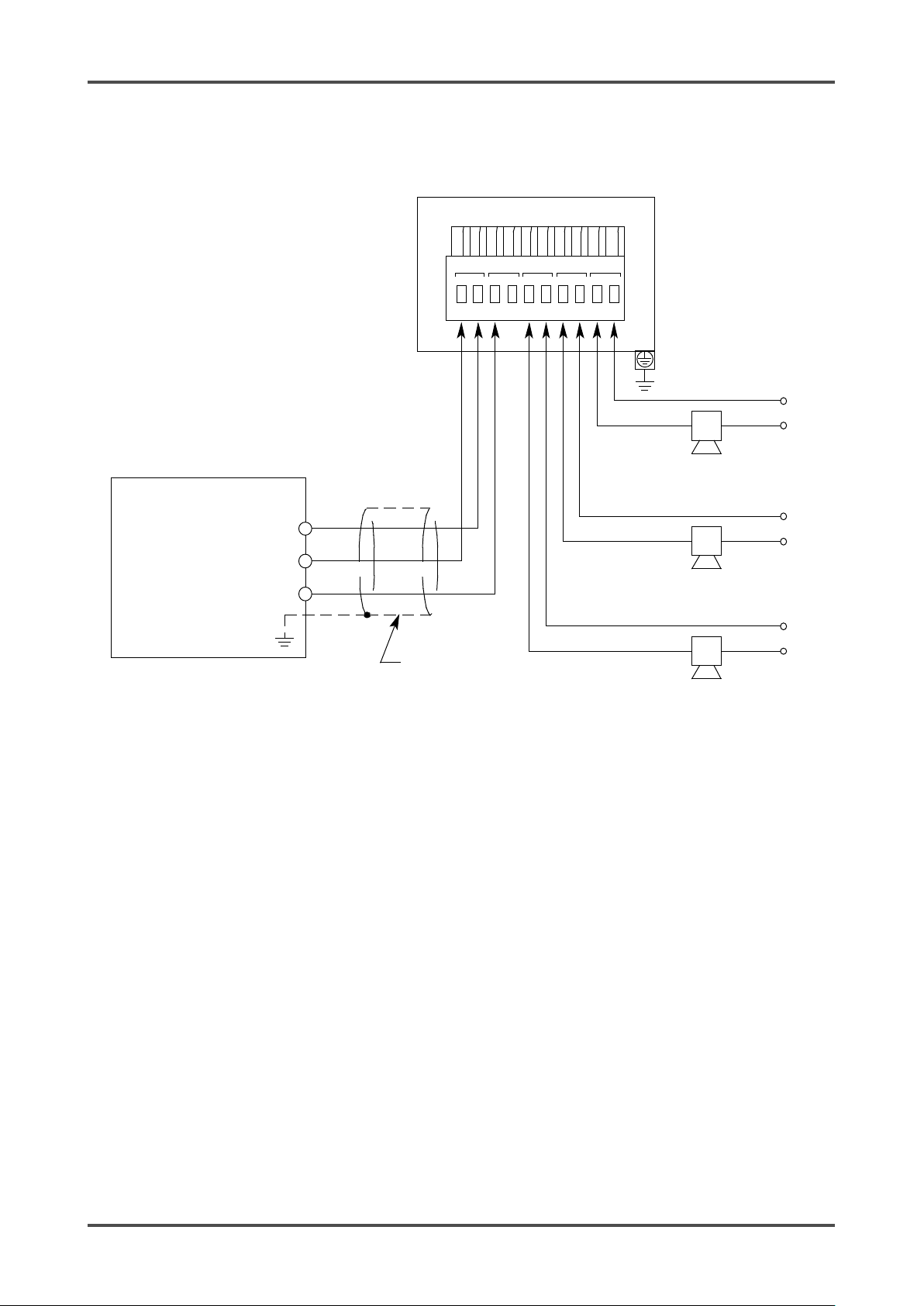
ALM2
FAULT
3
4
5
6 7
8
9
10
+
-
ALM1
4-20mA
Device
Power
Device
Power
Alarm
1
Device
Alarm
2
Device
Fault Alarm
Device
+
24VDC
Controller
orRecording
Device
1
+
- (DC Ground)
4
-
20mA
In (FB)
GD-70D Terminal
Plate
DC24V
2
-
Cable
Shield
Device
Power
Generic Controller Wiring
GD-70D - 26 -
Page 27

FAULT
3
4 5 6
7
8 9
10
+
-
ALM1
4-20mA
ALM2
Device
Power
Device
Power
Alarm
1
Device
Alarm 2
Device
Fault Alarm
Device
Power Supply
1
+
- 24VDC
+24 VDC
Device
Power
+
-
PLC orDCS
Cable
Shield
CableShield
GD-70D
TerminalPlate
DC24V
2
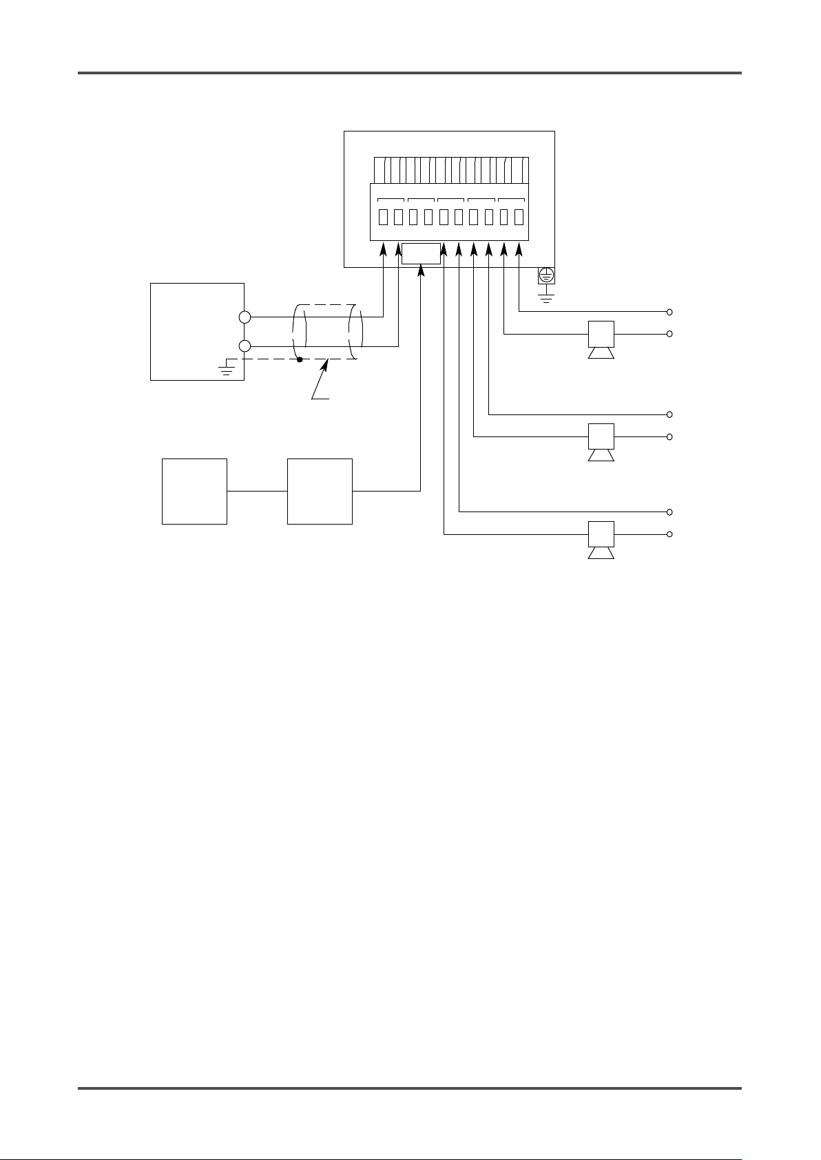
-
PLC or DCS Wiring
- 27 - GD-70D
Page 28
FAULTALM2
4-20mA
ALM1
-
+
10
9876543
Fault Alarm
Device
Alarm 2
Device
Alarm 1
Device
Device
Power
Device
Power
13
14
12
+
1
Device
Power
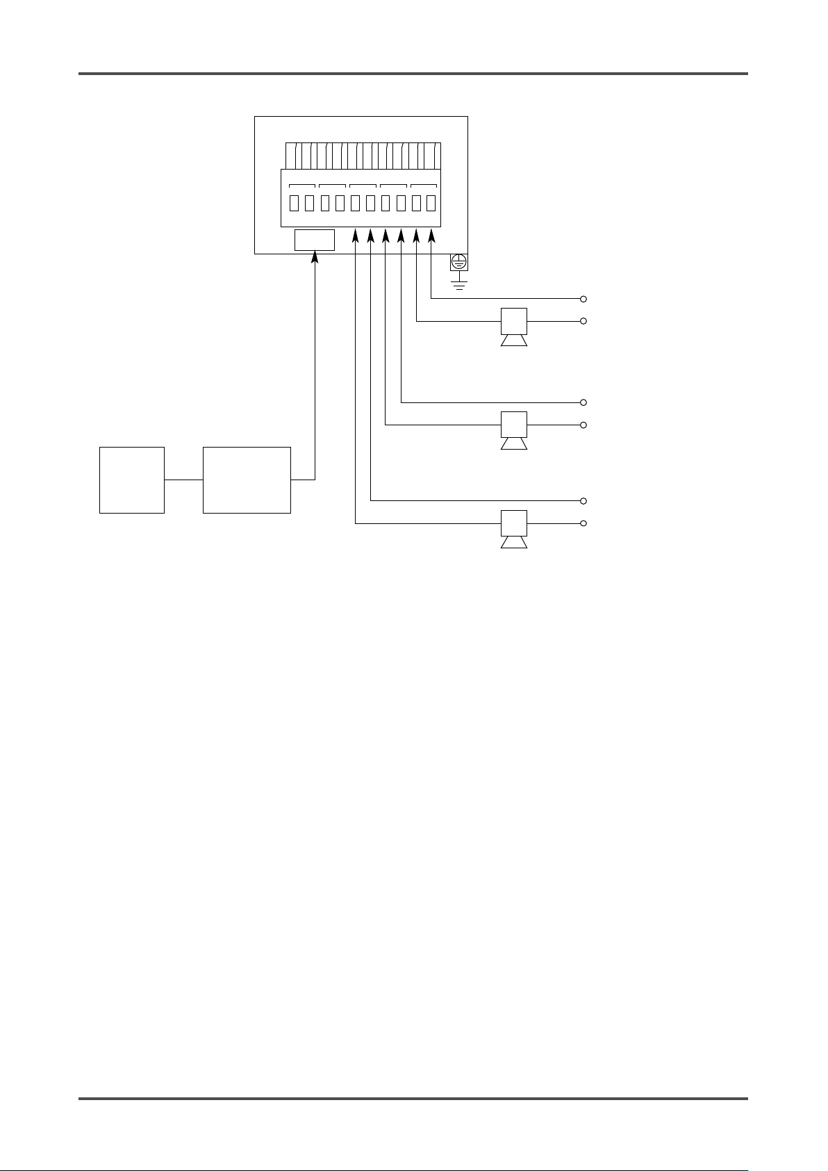
11
RM-5003
Cable
Shield
-
2
DC24V
GD-70D TerminalPlate
RM-5003 Wiring
GD-70D - 28 -
Page 29
76543
FAULT
ALM2
4-20mA
ALM1
-
+24 VDC
Fault
Alarm
Device
Alarm 2
Device
Alarm 1
Device
Device
Power
Device
Power
RJ45
Connector
+
10
98
Switching
Hub
PC or
PLC
+
1
Power
Supply
Device
Power
-
24VDC
-
2
DC24V
GD-70D Terminal
Plate
Cable
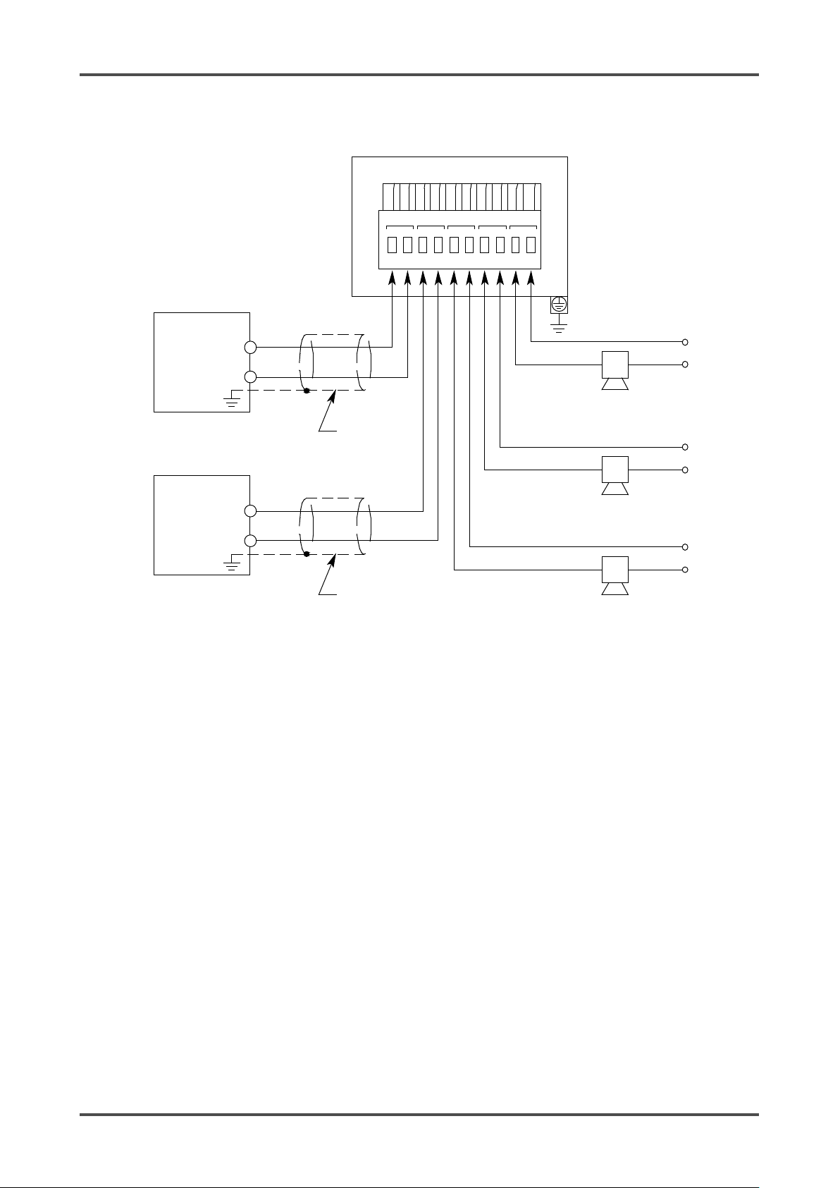
Shield
Ethernet Wiring
- 29 - GD-70D
Page 30
9
10
+
-
ALM1
4-20mA
ALM2 FAULT
3
4
5 6
7 81
+
Device
Power
Device
Power
Alarm 1
Device
Alarm 2
Device
Fault Alarm
Device
PC or
PLC
Switching Hub
(with PoE
Functionality)
RJ45
Connector
GD-70D TerminalPlate
DC24V
2
-
Device
Power
PoE Wiring
GD-70D - 30 -
Page 31
FAULT
ALM2
ALM1
-
Device
Power
LON
WORKS
+
10
98
7
65
4
3
Power
Supply
+
24
VDC
Fault Alarm
Device
Alarm 2
Device
Alarm
1
Device
Device
Power
+
1
Device
Power
LON
- 24
VDC
-
2
DC24V
GD-70D
Terminal
Plate
Cable
Shield
CableShield
LON Wiring
- 31 - GD-70D
Page 32

3 4 5 6 7 8 9 10
+
-
ALM1
4-20mA
ALM2
FAULT
Device
Power
Alarm 1
Device
Alarm 2
Device
Fault Alarm
Device
1
+
Device
Power
Blocking Filter
(B/F)
+
-
Power
Supply
(24 VDC)
DC
24V (-)
DC
24V(+)
Upper
Unit
(RM-70NT)
GD-70D-NT
Terminal
Plate
DC24V
2
-
Cable
Shield
+ -
Device
Power
Position the
RM-70NT Wiring (for GD-70D-NT)
<How to Clamp Cables>
1. Insert the supplied zip tie into the hole on the mounting plate
as shown in the figure to the right.
2. Position the zip tie so that its coarse side faces the wires.
3. Tighten the zip tie to secure the wires.
NOTE
When an optional cable gland is used, it must
be attached to the external wiring hole.
band so that
its coarse
side faces the
wire.
GD-70D - 32 -
Page 33

Grounding screw (M4)
Bottom
When the main unit is fully
10mm
When reinstalling the main unit,
plate hook before pushing down.
The lock clicks.
<Grounding>
Use the grounding terminal to connect the detector to your
grounding circuit.
WARNING
• Before turning on the detector, do not forget to connect it
to a grounding circuit.
• For stable operation of the detector and safety, it must be
connected to a grounding circuit. Do not connect the
grounding wire to a gas pip e. The groundi ng must be
made as D type grounding (below 100 Ω of grounding
resistance).
<Attaching Main Unit to Mounting Plate>
1. Make sure power to the detector is turned off.
2. Position the main unit about 10 mm above the mounting
plate.
3. Lower the main unit toward the mounting plate. Be sure both
mounting plate hooks fit into the main unit grooves.
4. Press down on the main unit to secure it. The lock at the
bottom of the main unit clicks to fix it properly.
5. Make sure that the top center of the mounting plate is above
the main unit as viewed from front. If it is not, push the main
unit down farther.
align the arrow mark on the side
of the housing with the mounting
installed on the mounting plate,
the top of the mounting plate will
protrude above the main unit.
- 33 - GD-70D
Page 34

4mm x 6 mm
Teflon Tubing
Nut
Tubing Insert
Ferrule
Dust Filter
Gas Inlet
To Sample Area
4-7 Making Tubing Connections
NOTE
To use the pyrolyzer unit (PLU-70), also refer to the individual operating manual.
1. The tube nut, ferrule, and tubing insert are shipped uninstalled and the open GAS IN and GAS OUT
fittings are plugged with protective rubber caps. Remove the rubber caps from the GAS IN and GAS
OUT fittings.
2. Install a short piece of 4 mm x 6 mm Teflon tubing to the GAS IN fitting as shown below. Be sure the
tubing insert, ferrule, and nut are installed properly.
3. Connect the dust filter to the tubing.
4. Install another piece of 4 mm x 6 mm Teflon tubing to the other end of the dust filter and route it to the
sample area.
5. Attach 4 mm x 6 mm Teflon tubing to the GAS OUT fitting and route it to a safe area. Be sure to use
the tubing insert, ferrule, and nut as shown above.
GD-70D - 34 -
Page 35

leading to dangers. Be sure that excessive pressure is not applied to the detector during use.
Please contact RKI for help determining an inlet tubing length.
Manual". We wil l p rope rly di sp o se o f it . Ig no ring the "Sa fe ty Manual" will result in legal p enal tie s.
WARNING
• The detector is designed to draw gas under normal atmospheric pressure. If excessive pressure is
applied to the GAS IN or GAS OUT fitting, detected gases may be leaked from its inside, thus
CAUTION
• Keep the inle t li ne a s sho rt as po ssi ble to mini mize the abs or pti on o f ga s by th e sa mple t ubin g.
• When the humidity in the sampling point is high, condensation may be formed inside of the tube.
Make sure to avoid condensation when detecting water-soluble gases such as a strong acid gas,
because it may corrode internal parts. Also avoid loopi ng or kinking th e tubing .
•
4-8 Disposal
• A used sensor unit must be returned to RKI.
• If any liquid leaks from the electrochemical type sensor unit (ESU) or galvanic cell type sensor unit (OSU),
do not touch the li qui d. I f any l iqu id lea ks w hi le th e sen sor uni t i s in s tal led in t he de tecto r, turn off power to
the detector and contact RKI immediately.
• Because the pyrolysis-particle type sensor unit (SSU) contains a small amount of radioactive materials, it
must be transported appropriately (as a L-type package). When the sensor unit is returned to us, it must be
handled by a tran spo rtati on c o mpa ny whi ch can h andl e L -type packages.
• When the main unit is disposed of, it must be treated properly as an industrial waste in accordance with the
local regulation s.
WARNING
• Do not disassemble the electroche mical ty pe sensor uni t (ESU) or the gal vani c cell type sen sor unit
(OSU) because t hey con tain el ec t roly te.
Electrolyte may cause severe skin burns if it contacts skin and may cause blindness if it contacts
eyes. Electrolyte may damage or discolor clothing. If contact occurs, rinse the area immediately with
a large quanti ty o f wate r .
• The pyrolysis-particle type sensor unit (SSU) must be returned to us in accordance with its "Safety
- 35 - GD-70D
Page 36

OFF
ON
Slide
Switch cover closed.
Switch cover open.
Power switch
5
Operation
5-1 Preparation for Start-up
Before connecting a power supply, read and understand the following precautions. Ignoring these
precautions may cause an electric shock or damage the detector.
• Connect the detecto r to a groundi ng cir cuit.
• Ensure the wiring is correctly connected to the external circuit.
• Ensure the main unit is properly installed on the mounting plate.
• Ensure the power supply voltage i s approp riate (s ee Specifi cation s).
• Alarm contacts may be activated during startup. Take steps to ensure this does not have any unwanted
effects.
• Verify that the GAS IN and GAS OUT lines are clear.
• Verify that the dust filter is installe d corre ctly.
5-2 Starting Up the Detector
1. The power switch is protected by a cover to prevent accidental
access. Rotate the switch cover to gain access to the power
switch. (Return the switch cove r to the original position once
you are done.)
2. Turn ON the power switch.
3. After the detector completes the start-up, it enters Detection
Mode.
(under cover)
GD-70D - 36 -
Page 37

Power On
↓
PW
A1
A2
F
LCD
Initial Clear
● ○ ○
○
──────
↓
↓
Gas
● ○ ○
○
15.0ppm
↓
↓
Detection Mode
● ○ ○
○
0.0ppm
started.
PW:POWER
F:FAULT
●
<Warm-up Sequence>
The warm-up taking approximately 25 seconds to complete.
A1:ALM1
A2:ALM2
WARM UP
Specifications
Display
SIH4
SIH4
WARNING
• When Oxygen (OSU) is selected, fresh air (20.9 vol%) is
the output after the detector is started in the atmosphere.
For a specification where an alarm is triggered by the
AIR (normal oxygen concentration) output (e.g., 0 - 5
vol%), be careful of an alarm issue after the detector is
CAUTION
• Do not turn off the detector during the initial clear. The detector is reading the sensor memory during
the initial clear.
• If a new sensor unit is installed or the sensor unit is replaced after the detector is started, the sensor
unit must be w armed up fo r a spe ci fied pe rio d w hi ch i s de te r mined d epen din g on the type of the
sensor unit. Suggested warm-up time for SGU ty pe senso r un it s i s di splay ed in Mai nt ena n ce Mod e.
During the warm-up, the alarm activation and output signals are unstable. Prepare appropriately for
false alarms.
• Because the pyrolyzer unit (PLU-70) must be warmed up for one hour, please warm it up with the
detector.
• After the warm-up is completed, verify that the reading on the flow rate indicator corresponds to the
specified flow rate, and then perform a gas calibration.
:Lamp on
○:Lamp off
- 37 - GD-70D
Page 38

"OFF" the detector.
<<Detection Mode>>
PW
A1
A2
F
LCD
● ○ ○
○
0.0ppm
<<User Mode>>
PW
A1
A2
F
LCD
● ○ ○
○
1- 1
MAINTENANCE
<<Maintenance Mode >>
PW
A1
A2
F
LCD
● ○ ○
○
2- 0
MAINTENANCE
<<Gas Alarm Test Mode>>
PW
A1
A2
F
LCD
● ○ ○
○
0.0ppm
MAINTENANCE
<<Fault Alarm Status>>
PW
A1
A2
F
LCD
● ○ ○
●
E-5
<<Gas Alarm Status>>
PW
A1
A2
F
LCD
● ● ○
○
6.0ppm
MODE
TEST
The detector is
MODE
PW:POWER
F:FAULT
●
5-3 Turning Off the Detector
To turn off the detector, open the switch cover on the bottom of the main unit, and turn "OFF" the power
switch. Then, turn off the power supply (24 VDC) to the detector.
WARNING
• When the detector is turned off, an alarm may be activated on the up pe r ( cent ral) system.
Before turning off the detector, the inhibit (point skip) on the upper (central) system must be
activated.
Decide whether the power can be turned off by checking the operation of the devices connected to
the external output or external contact output terminal of the detector.
• If the alarm contact is energized (option), they will activate when the detector is turned "OFF".
• If the detected gas is absorptive, the detector must be flushed thoroughly with fresh air before turning
5-4 Basic Operation
After the warmup procedure, the detector enters detection mode.
restarted after
recovering from
Fault.
SIH4
FLOW
TEST OFF
SIH4
(press and hold)
(press and hold)
A1:ALM1
A2:ALM2
GAS TEST
:Lamp on
○:Lamp off
(press and hold)
ZERO
GD-70D - 38 -
Page 39

Mode
Item
LCD Display
Details
Detection
Mode
-
Gas concentration
Gas name
Normal state
Gas Alarm
Test Mode
User Mode
Zero Adjustment (Span
1-1 ZERO
oxygen)
Perform the zero adjustment (span adjustment for oxygen).
• Sensitivity c orrection ON/OFF
Flow Rate Indicator
1-3 FLOW
Show the current flow rate.
Address Display
1-4 ADDRESS
Show the address.
Detector Version Display
1-5 70D VER
Show the program version of the main unit.
Unit Version Display
1-6 UNIT VER
Show the program version of the sensor unit.
Net Version Display
1-7 NET VER
Show the program version of the communication function.
Access
this case, you must identify the causes and take appropriate actions.
Flow rate
Flow rate
Normal
flow rate
WARNING
• When the detector enters each mode from Detection Mode while an alarm is activated, the alarm
contact is released.
<Detection Mode>
Flow Rate Indicator
Because the suction flow rate of the detector is automatically adjusted by the flow rate control function, the
flow rate, in principal, does not need to be controlled. As shown on the figure below, when the flow rate
does not correspond to the specified flow rate for some reasons, it is adjusted automatically.
CAUTION
• If the automatic flow rate adjustment does not wo rk (due to clogg ed tube or lea k), you may get a
"FLOW" message (for an unstable flow rate) or an "E-05" message (for flow rate abnormal iti es). In
too low
too high
5-5 Modes
Details on each mode are provided as follows. (* Operations are slightly different depending on the
detector type or sensor unit.)
- Gas concentration Perform the alarm test.
(see pg. 59)
Adjustment for oxygen)
Setting Display 1-2 CONFIRM S how the setting of typical menus.
Maintenance Mode
(1-1 SPAN for
First alarm setpoint (AL1)
•
•
Second alarm setpo int (AL2)
•
Alarm delay time
•
Zero suppression value
•
Zero follower ON/OFF
1-8 M MODE Enter maintenance mode.
- 39 - GD-70D
Page 40

Mode
Item
LCD Display
Details
Maintenance
Gas Introduction Display
2-0 GAS TEST
Perform the gas introduction test.
Zero Adjustment
2-1 ZERO
Perform the zero adjustment.
Span Adjustment
2-2 SPAN
Perform the span adjustment.
Last Calibrated Date
2-3 LAST CAL
Show the last calibrated date.
Voltage)
(2-4 E VOLT)
(Show the element voltage.)
Flow Rate Setting
(adjust ed to 0.5 L/m in)
2-5 DEF FLOW
Set the flow sensor wit h the flow ra te at 0.5 L/min.
Indicator
Detector Temperature
2-7 TEMP
Show the current temperature of the installation environme nt.
Completion Date/Time
(SGU).
Environmental Set ting 1
2-9 SETTING1
Operation settings
Fault test (F TEST)
• Pump drive level diagnosis ON/OFF setting (PUMP CK)
Pyrolyzer Data Display
2-11 PL DATA
If a pyrolyzer unit is being used, this menu displays data for it (see
the PLU-70 operator’s manual for more description)
Fault Investigation
2-12 FAULT
Not used
Factory Mode Switching
2-13 F MODE
Not used
Mode (see pg.
67)
Bias Voltage (Element
Pump Ratio/Flow Rate
Suggested Warm-up
Environmental Set ting 2 2-10 SETTING2 Function settings
2-4 BIAS
2-6 FLOW Show t h e output and flow rate of the current pump.
2-8 WARMTIME Show the suggested warm-up completion for semiconductor type
Show the bias voltage.
• INHIBIT setting (INHIBI T)
•
Alarm value setting (ALM P)
•
Alarm delay time setting (ALM DLY)
•
Regular replacement operation (pump stop) (MAINTE)
•
•
Address setting (ADDRESS)
•
Date/ Time s etting ( D AY TIME)
•
Zero suppression value setting (SUPPRESS)
•
Zero suppression system setting (SUP TYPE)
•
Alarm test time contact setting (TEST RLY)
•
Alarm test time external output setting (TEST4-20)
•
Energized/De-energized setting (RLY PTRN)
•
Alarm type setting (ALM TYP)
•
Alarm activa ti on setting ( A LM PTRN)
•
Alarm value limiter setting (AL LIMIT)
•
Fault activation setting (FLT PTRN)
•
Flow ra te auto-adjustment setting (AT FLOW)
•
Zero follower ON/OFF setting (ZERO F)
•
24 hours zero follower ON/OFF setting (ZERO 24F)
•
Sensitivity correctio n O N/OFF setting (S ASSIST)
•
External output in maintenance mode setting (MNT OUT)
•
External output adjustment (MA 4-20)
•
Backlight setting (BK LIGHT)
•
ETHERNET setting (ETHERNET)
GD-70D - 40 -
Page 41

6
Detection Mode
6-1 Gas Alarm Activation
A gas alarm is activated when the concentration of detected gas reaches or exceeds the alarm setpoint.
This section describes alarms assuming an auto-reset operation.
NOTE
The alarm setpoint (first alarm and second alarm) is factory set.
The alarm delay time (standard: 2 seconds) is enabled in the detector to prevent a false activation. It can
be disabled, if desired.
<Display Operation During Alarm Condition>
Gas Concentration Display
The gas concentration is displayed on the LCD. If the concentration is above the detection range (over
scale), "∩∩∩∩" is displayed on the LCD instead of the gas concentration.
Alarm Indicator Lamp (ALM1: Red), (ALM2: Red)
When the first alarm setpoint has been reached, the ALM1 LED turns red.
When the second alarm setpoint has been reached, the ALM2 LED turns red.
GD-70D - 41 -
Page 42

<Contact Activation>
The contact is activated when the gas concentration reaches or exceeds the alarm setpoint. The contact
activation is reset automatically when the gas concentration drops below the alarm setpoint.
<Contact Activation (Auto-reset)>
In case of Auto-reset setting, the contact is activated when the gas concentration reaches or exceeds the
alarm setpoint value. The contact activation is reset automatically when the gas concentration drops below
the alarm setpoint value.
NOTE
In DETECTION MODE, select and press one of the following key to reset : “MODE”, “▲”, “▼” or
“TEST/SET”.
"Alarm Pattern (H-HH)"
GD-70D - 42 -
Page 43

"Alarm Pattern (L-H)"
"Alarm Pattern (L-LL)"
(* oxygen deficiency alarm)
- 43 - GD-70D
Page 44

<Contact Activation (Self-latching)>
In case of Self-latching setting, the contact is activated when the gas concentration reaches or exceeds the
alarm setpoint value. The alarm indication lamp blinks during warning. It changes to a light after reset is
performed. It turns off when the gas concentration drops below the alarm set point value.
"Alarm Pattern (H-HH)"
GD-70D - 44 -
Page 45

"Alarm Pattern (L-H)"
- 45 - GD-70D
Page 46

"Alarm Pattern (L-LL)"
<Response to Gas Alarm>
When a gas alarm is triggered, take actions in accordance with your company’s safety practices for a gas
alarm. In general, take the following actions.
1. Check the reading of the detector.
NOTE
If a gas leak is momentary or if the alarm is triggered by noise, the reading may already have dropped by
the time you get to the instrument to check it.
2. Based on your company’s safety practices, no one can be allowed to a cces s t he monit ored z one to en su re
safety.
3. If the detector display is still indicating the presence of gas, close the area’s main gas valve, and then verify
that the detector’s gas concentration readin g dropp ed.
4. While wearing protective equipment in case gas is still present, use a portable gas detector to ensure the
area is free from gas.
5. If you can determine that the leak point is free from dangers, take actions to fix the gas leak.
GD-70D - 46 -
Page 47

Specifications/Condition
4 - 20 mA (for GD-70D)
Power-line communication system
* E-5 FLOW (flow rate abnormalities)
6-2 Fault Alarm Activation
A fault alarm is triggered when the detector detects
abnormalities.
After a fault alarm is triggered, the FAULT lamp (yellow) lights up
and an error message is displayed on the LCD.
Determine the causes and take appropriate actions.
After the detector is successfully returned from the fault, it
restarts and goes through a normal warmup procedure.
If the detector has problems and is repeatedly malfunctioning,
please contact RKI immediately.
NOTE
For information on error messages and possible malfunctions, see Troubleshooting on page 116.
6-3 External Output Operation
● 4 - 20 mA/NT/EA Specification
Signal Transmission System Electric current transmission (non-isolated)
Transmission Path CVVS KPEV-S
Transmiss ion Distance Below 1 km
Connection Load Resistance Below 300 Ω -
Detection Mode (No Alarm) 4 - 20 mA (concentration output) Concentration data
Detection Mode (Gas Alarm) 4 - 20 mA (concentration output) Concentration data, Alarm bits
Initial Clear
Maintenance Mode
Alarm T est
Depending on the setting of
2.5 mA setting: 2.5 mA
4 mA, HOLD, 4-20 mA setting: 4 mA*
2.5 mA setting : 2 .5 mA
4 mA setting: 4mA*
HOLD Setting: the previous value retained
4-20 mA setting: 4 - 20 mA (concentration output)
Output ON setting: 4 - 20 mA (concentration output)
Output OFF setting: In accordance with setting of
Fault Alarm 0.5 mA (Fixed) Fault bits
Inhibit
Power Off 0 mA Signal OFF
Depending on the setting of
2.5 mA setting : 2 .5 mA
4 mA, HOLD, 4 - 20 mA setting: 4 mA*
* 17.4 mA for oxygen units
2-wire type DC power-line communication
system
Below 300 m (depending on the system
designing conditions)
Initia l bit
Concentration data, Adjustment bit
Concentration data, Adjustment bit, Test bit
Concentration data, Adjustment bit, Inhibit bit
(for GD-70D-NT)
- 47 - GD-70D
Page 48

Specifications
LONWORKS (LN)
Signal
method
Transmission
path
Transmission
rate
Transmission
distance
Max 2700m
* When bus topology (Double ended termination ) is used.
Connection load
resistance
Maintenance output setting
Sensor unit
Details
2.5 mA
Use OSU (L-LL, L-H).
Output 2.5 mA during maintenance or inhibit.
alarm)
4 mA, HOLD, 4 - 20 mA
Specification change
When changing from a H-HH alarm pattern to
change message is confirmed.
Specification change
When changing from an L-LL or L-H alarm
“C-02” change message is confirmed.
2.5mA
4mA
20mA
22mA
Full scale
Gas concentration
External output
Zero
suppression
Detection mode
Maintenance mode
● LN Specification
transmission
Example of Gas Concentration and External Output
4 - 20 mA Specification
(Maintenance output: 2.5 mA setting)
CAUTION
<<4 - 20 mA Specification>>
• The 4 - 20 mA output is already adjusted. In case of over scale, an output will not exceed 22 mA.
• Output during inhibit or warmup is based on 4 - 20 mA output setting in Mai ntenan ce Mode.
Special Cases>
<
LONWORKS
KPEV-S
78kbps
―
The output may dro p a s low a s 2 .5 mA du rin g wa r mup for o xygen uni ts . Unde r stand how the
detector functions, and take actions to prepare for false alarms.
Possibility of false alarm in the upper unit (L
(To OSU - 0 - 25 v ol%)
(From OSU - 0 - 25
vol%)
an L-LL or L-H alarm pattern, 4 mA (equivalent
of concentration zero) is used until the “C-02”
pattern to a H-HH alarm pattern, 17.4 mA
(equivalent of approx. 84%FS) is used until the
GD-70D - 48 -
Page 49

GD-70D-
Power-line
system
The detector is used in a local net work formed with a multi-displa y unit (RMmulti-display unit.
GD-70D-
Ethernet
The detector offers functions that work in liaison with external software using
value or perform calibration and test.
GD-70D-
LONWORKS
An internationally standardized network specification for device control. It is a
flexibility.
<Communication Specifications>
NT
communication
EA
LN
70NT) as the base unit. For more information, see the operating manual of the
a standard network protocol. For details, see the separate manual for
communication function.
Web function (HTTP), mail send function (SMTP), and time synchronization
function (SNTP)
Use a Web browser of an upper-unit PC to view and change setting values
and perform calibration and test on a graphical user interface.
SMTP, when receiving a gas alarm or fault alarm from an external mail
server, can send a notification mail to a registered address.
SNTP, receiving time information from a time server, can correct the clock at
regular intervals.
Modbus slave function (Modbus/TCP)
Works as a Modbus slave and feeds back a setting value in response to a
read request or changes a setting value in response to a write request.
PLC linkage function (FINS・MC)
Sends a setting value to PLC to provide information to be processed by PLC
in a ladder program. Reading from PLC is also available to change a setting
network specification that controls and manages not only gas detectors but
also air conditioning, lighting etc. equipment by the same communication
protocol called Lon-talk.
By constructing an open system, it becomes possible to connect the system
without being bound by one manufacturer, it is possible to facilitate
procurement of parts at the time of equipment failure, and to increase design
- 49 - GD-70D
Page 50

<<Example: SiH4 0 - 15 ppm range>>
0.5ppm
SIH4
Suppression Disabled
↓
0.0ppm
SIH4
Suppression Enabled
6-4 Other Functions
<Suppression Function>
Some sensors are influenced by environmental changes (temperature, humidity, and other characteristics)
or interference gases which may cause the reading to vary in fresh air.
The suppression function is used to hide (suppress) the variation of the reading under the set suppression
value, so that the display indicates zero (or 20.9% for oxygen) until the reading exceeds the set
suppression value.
The factory setting for the suppression function is OFF for every gas type except for oxygen.
A variation around zero is displayed as the reading.
A variation under the set suppression value (ie. 6% of full scale or 0.9 ppm for
CAUTION
• If the zero reading is BELOW zero, the reading wil l not chang e until the reading reache s -10% of full
scale.
• A reading that is -10% of full scale is di splay ed as "-0.0".
SiH4) is shown as zero.
GD-70D - 50 -
Page 51

sensor. To correct the sensitivity variation, you must regularly calibrate the sensor.
* The zero drift is periodically corrected to bring the
Zero Follower On
Zero Follower Off
* The zero drift of the sensor appears as the reading.
Reading
Zero point
0
Time
↓
Zero point
0
Reading
Time
Sensitivity Correction Off
* Sensor accuracy decreases.
Sensitivity Correction On
* The span is periodically lifted to
increase sensor accuracy.
↓
0
Time
Gas correction
Reading
Gas
0
Reading
Time
<Zero Follower Function>
Some sensors (ESU and SSU types) have
sensitivity variations after being used for a long
period of time.
The zero follower function uses program
manipulation to correct for sensitivity variat ions in
the zero reading.
<Sensitivity Correction
reading back to zero.
Function>
ESU type sensors have sensitivity variations after
being used for a long period of time.
The sensitivity correction function compensates for
decreasing gas sensitivity as the sensor gets older.
It periodically adjusts the span based on the
degradation pattern of the sensor.
correction
CAUTION
The sensitivity correction is just an auxiliary function. It uniformly lifts the span up based on the sensor’s
degradation pattern only. S en si tivity correction cannot consi de r th e sen siti vity v a riation o f a n i ndi vi dual
- 51 - GD-70D
Page 52

Unit Replacement
1. Press the MODE key to confirm the new sensor unit and start the monitor.
sensor might have been installed by mistake.
↓
C-02
MAINTENANCE
Specification Change
might mean there is an installation error. Check the sensor installation.
ESU SSU NCU SGU OSU
OSU
(0 - 5 vol%)
OSU
(0 - 50 vol%)
Alarm delay
2second
2-second
2-second
2second
2second
2second
2second
Suppression
value
6%FS 2 ppm
(TEOS)
6%FS
(0-100%LEL)
10%FS
0.5 vol%
0 vol%
0 vol%
Alarm type
H-HH H-HH H-HH H-HH L-LL H-HH H-HH
IRU
500ppm)
SHU
2000ppm)
Alarm delay
2second
2-second
Suppression
value
30 ppm
200 ppm
Alarm type
H-HH
H-HH
<Calibration History/Alarm Trend History/Event History
Functions>
The detector and the sensor unit have their own history functions. To use these functions, contact RKI.
<Sensor Unit Automatic Recognition Function>
The detector can automatically recognize when a new sensor has been installed. If a replacement sensor
of the same type is installed, the detector will display a “C-01 CHG UNIT” message. If a different type
sensor is installed, the detector will display a “C-02 CHG SPEC” message.
C-01
CHG UNIT
MAINTENANCE
Displayed when a unit with the same specif ic atio n (principle, type, range, and so
on) is attached (e.g. in a regular replacement).
The following is displayed alternately if the unit that you installed has the same
or earlier date of manufacture than the one that has been replaced.
"CHG UNIT" <=> "USED SEN"
*** Check for correct installation if this message is displayed because an old
Displayed when a unit with a different specification (principle, type, range, and
CHG SPEC
so on) from the previous one is attached.
1. Press the MODE key to confirm the new specification and start the monitor.
If you did not install a sensor unit with a different specification, this message
CAUTION
If you get a “C-02” message and confirm the specification change by pressing the MODE key, the
specification of the gas detect or head is changed. The followi ng paramet ers are ch anged to thei r standa rd
settings. If you want to use nonstandard settings, set them in Maint enan ce Mode.
• Alarm setpoints (ALM P)
• Alarm delay time setting (ALM DLY)
• Suppression value (SUPPRESS)
• Alarm type (ALM TYP) ...... The OSU speci fication includes "L-LL ", "L -H" , and "H-HH".
<Standard Setting Values by Principle>
(0-
(0-
GD-70D - 52 -
Page 53

PW
A1
A2
F
LCD
Detection mode
● ○ ○ ○
0.0ppm
↓
↓
1-1.ZERO
● ○ ○ ○
1- 1
MAINTENANCE
→
Zero Adjustment
6-5 About LONWORKS (LN specification)
<Binding method>
WARNING
≪User mode≫
Press the MODE key
for 3 seconds.
• When adjustment is completed, press the MODE key and be sure to return to detection
mode.
(When left in user mode, it automatically returns to detection mode after 10 hours.
SIH4
)
User mode
Perform the zero
adjustment.
To reissue the neuron ID, please press the MODE key in user mode for 3 seconds, return to the detection
mode, and enter the user mode again.
- 53 - GD-70D
SET
⇒P51
ZERO
Page 54

Open-lLoop Sensor Functional
Block
GD-70D-LN LonWorks Diagram
Virtual Function
Block
Mandato
ry
Implementation Specific
nviReset
SNVT_lev_disc
nvoConc
SNVT_ppm_f
nvoNstate
SNVT_state
nvoAlarmS
SNVT_switch
nviComand
SNVT_str_asc
nciMaxSendTM
SNVT_time_sec
nciMinSendTM
SNVT_time_sec
nciMaxSendTl
SNVT_time_sec
nciMinSendTl
SNVT_time_sec
nvoFaultS
SNVT_switch
nvoGasName
SNVT_str_asc
nvoHertBeat
SNVT_state
nvoComand
SNVT_str_asc
nciMaxSendHB
SNVT_time_sec
GD-70D - 54 -
Page 55

It is the same as the current density output.
part.
It is the same as the current density output.
Status of 16 BIT expresses measurement unit, alarm, breakdown etc.
Expression of alarm state by switch
1st & 2nd: {2.0,1}
Expression of fault condition by switch
: 9.0 = System fault
Send measured gas name and measurement unit in ASCII character
and the rest is ASCIL(00H = NULL)
Count up 8 BIT of 0 to 7 of 16 BIT
8 to 15 BIT is reserved.
7
nviReset
SNVT_lev_disc
RESET signal in case of self-latching 0:non not 0:RESET
8
nciMaxSendTM
SNVT_time_sec
1 and 2 update maximum time
9
nciMinSendTM
SNVT_time_sec
1 and 2 update minimum time
10
nciMaxSendTI
SNVT_time_sec
3 ~ 5 update maximum time
11
nciMinSendTI
SNVT_time_sec
3 ~ 5 update minimum time
5
nciMaxSendHB
SNVT_time_sec
6 update maximum time
13
nviComand
SNVT_str_asc
Command input of ASCII 30 byte
14
nvoComand
SNVT_str_asc
Command output of ASCII 30 byte
NO. Variable name Variable type Contents
1 nvoConc SNVT_ppm_f
2 nvoNstate SNVT_state
3 nvoAlarmS SNVT_switch
4 nvoFaultS SNVT_switch
5 nvoGasName SNVT_str_asc
6 nvoHertBeat SNVT_state
Floating point of 16 BIT synchronizes with the display of the detection
OFF:{0.0,0}
:{1.0,1}
1st
2nd :{1.5,1}
Normal:{0.0,0}
Fault:{X.X,1} - - X.X : 1.0 = Sensor fault
: 5.0 = Flaw rate fault
: 7.0 = Pyrolyzer fault
string.
From the beginning, we send unit after space (20H) with gas name
Count every second and count it. If it is OVER, start with 0.
You can select the transmission status with the combination of the setting point of nciMaxSendTM (8) and
nciMinSendTM (9).
・nciMaxSendTM (8) = Asec nciMinSendTM (9) = Bsec --> (1) and (2) transmit every Asec when
there is no VAL update. If Bsec has not elapsed since last transmission, wait until Bsec has elapsed
before sending it even if VAL is updated.
・nciMaxSendTM (8) = Asec nciMinSendTM (9) = 0sec --> (1) and (2) tra nsm it every Asec when
there is no VAL update. If there is an update of VAL, it will be sent immediately.
・nciMaxSendTM (8) = 0sec nciMinSendTM (9) = Bsec --> (1), (2) don’t transmit every Asec
when there is no VAL update. If Bsec has not elaps ed sinc e last trans mission, wait until Bsec has elapsed
before sending it even if VAL is updated.
You can select the transmission status with the combination of the setting point of nciMaxSendTI (10) and
nciMinSendTI (11).
・nciMaxSendTI (10) = Asec nciMinSendTI (11) = Bsec --> (3) ~ (5) transmit every Asec when
there is no VAL update. If Bsec has not elapsed since last transmission, wait until Bsec has elapsed
before sending it even if VAL is updated.
・nciMaxSendTI (10) = Asec nciMinSendTI (11) = 0sec --> (3) ~ (5) trans mit every Asec when
there is no VAL update. If there is an update of VAL, it will be sent immediately.
・nciMaxSendTI (10) = 0sec nciMinSendTI (11) = Bsec --> (3) ~ (5) don’t transmit every Asec
when there is no VAL update. If Bsec has not elaps ed sinc e last trans mission, wait until Bsec has elapsed
before sending it even if VAL is updated.
- 55 - GD-70D
Page 56

You can select the transmission status with the setting point of nciMaxSendHBb(12)
・nciMaxSendHB (12) = Asec --> (6) transmit every Asec.
・nciMaxSendHB (12) = 0sec --> (6) don’t transmit every Asec.
It outputs to nvoComand (14) for input data of nviComand (13).
・nviComand (13) = "A1, R," --> nvoComand (14) = "A1, R, ××××"
××× express 1st alarm point read value in hexadecimal.
・nviComand (13) = "A2, R," --> nvoComand (14) = "A2, R, ××××"
×××× express 2nd alarm point read value in hexadecimal.
・nviComand (13) = "AD, R," --> nvoComand (14) = "AD, R,××××"
×××× express Alarm delay time (mesc 10 units) read value in hexadecimal.
GD-70D - 56 -
Page 57

PW
A1
A2
F
LCD
Detection Mode
● ○ ○
○
0.0ppm
↓
↓
Alarm Test Mode
pressing the ▲ or ▼ key.
● ○ ○
○
0.0ppm
MAINTENANCE
↓
↓
First Alarm
● ○ ○
○
5.0ppm
MAINTENANCE
↓
Second Alarm
alarm contact is activated.)
● ○ ○
○
10.0ppm
↓
hours.)
7
Alarm Test Mode
Alarm Test Mode generates dummy signals that imitate gas concentration signals in order to check the
alarm LED activation and the transmission to external circuits.
WARNING
• Before starting the alarm test (transmission test), prepare for false alarms by disabling alarms or
Be sure that the TEST RLY and TEST4-20 items in Maintenance Mode are set appropriately.
alerting approp ria te pe rsonnel.
• After the test is completed, do not forget to press the TEST key to return to Detection Mode.
(If the detector remains in the alarm test mode, it automatically returns to Detection Mode in ten
7-1 Alarm Test Mode
Press the TEST key for three seconds.
"TEST ON" is displayed when the alarm
contacts will activate during the alarm
test. "TEST OFF" is displayed when the
alarm contacts will not activate during
the alarm test. (The setting can be
changed in the TEST RLY menu item in
Maintenance Mode.)
Increase or decrease the reading by
When the reading reaches the first
alarm, the ALM1 lamp lights up. (When
TEST RLY is set to ON, the first alarm
contact is activated.)
SIH4
TEST OFF
TEST OFF
When the reading reaches the second
alarm, the ALM2 lamp lights up. (When
TEST RLY is set to ON, the second
GD-70D - 57 -
↓
TEST OFF
MAINTENANCE
Page 58

Return to Detection Mode
Press the TEST key for 3 seconds.
GD-70D - 58 -
Page 59

PW
A1
A2
F
LCD
Detection Mode
● ○ ○
○
0.0ppm
↓
User Mode
↓
1-1.ZERO
● ○ ○
○
1- 1
MAINTENANCE
Zero Adjustment
↓ ↑▼
● ○ ○
○
1- 2
MAINTENANCE
Setpoint Display
↓ ↑▼
● ○ ○
○
1- 3
MAINTENANCE
0.50
MAINTENANCE
↓ ↑▼
● ○ ○
○
1- 4
MAINTENANCE
01
MAINTENANCE
↓ ↑▼
After the adjustment is completed, do not forget to press the MODE key to return to Detection Mode.
WARNING
8-1 User Mode
8
User Mode
Press the MODE key for
three seconds.
Perform the zero
adjustment.
1-2.CONFIRM
Show the typical setpoint.
1-3.FLOW
Show the current flow rate.
SIH4
ZERO
▲
CONFIRM
▲
FLOW
→
SET
→
SET
→
SET
⇒P62
⇒P63
L/M
▲
1-4.ADDRESS
Show the address.
(for GD-70D-NT)
GD-70D - 59 -
ADDRESS
▲
SET
→
ADDRESS
Page 60

● ○ ○
○
1- 5
MAINTENANCE
01234
MAINTENANCE
↓ ↑▼
● ○ ○
○
1- 6
MAINTENANCE
01234
MAINTENANCE
↓ ↑▼
(for GD-70D-NT)
● ○ ○
○
1- 7
MAINTENANCE
01234
MAINTENANCE
↓ ↑▼
1-8.M MODE
● ○ ○
○
1- 8
MAINTENANCE
See Maintenance
↓ ↑▼
To 1-1.ZERO
【
1-7. NET VER
(NT specification)
● ○ ○
○
1- 7
→
01234
↓↑
1-8.COM SET
confirm the value.
● ○ ○
○
1- 8
⇔
A
↓↑
|↑
A: Analog transmission
E
MAINTENANCE
▲↓↑▼
EA
MAINTENANCE
1-5.70D VER
Show the program version
of the main unit.
1-6.UNIT VER
Show the program version
of the installed sensor unit.
1-7.NET VER
Show the program version
of the communication
function.
Enter Maintenance Mode.
70D VER
▲
UNIT VER
▲
NET VER
▲
M MODE
→
SET
→
SET
→
SET
→
SET
56AB
56AB
----
Mode on page 65.
In case of GD-70D-EA】
Show the program
version of the
communication
function.
Set communication
output.
Press the ▲ or ▼ key
to select the
communication
output, and then press
the SET key to
E: Ethernet
EA: Ethernet and analog
transmission
GD-70D - 60 -
▲
NET VER
MAINTENANCE
▲
COM SET
MAINTENANCE
||
▲||▼
SET
----
MAINTENANCE
▼
SET
COM SET
MAINTENANCE
▲
▼
COM SET
COM SET
Page 61

1-9. M MODE
○ ○ ○
1- 9
MAINTENANCE
→
See Maintenance
↓↑
To 1-1. ZERO
Switch to the regular
maintenance mode.
M MODE
▲
▼
SET
Mode on page 65.
NOTE
• Communication output setting 1-8 (COM SET) is displayed only for EA specification.
• In EA specification, if only analog transmission is used (Ethernet is not used), if the communication
output setting is set to A, Communication Abnormalities E-6 does not occur even if an Ethernet cable
is not connected.
- 61 - GD-70D
Page 62

PW
A1
A2
F
LCD
From Detection Mode, press the
● ○ ○
○
0.0ppm
↓
↓
1-1.ZERO
● ○ ○
○
1- 1
MAINTENANCE
↓
↓
Current Concentration Value
● ○ ○
○
1.1ppm
MAINTENANCE
↓
↓
Zero Adjustment Completed
● ○ ○
○
0.0ppm
MAINTENANCE
↓
Return to 1-1.ZERO
* If the zero adjustment fail s .
● ○ ○
○
0.0ppm
MAINTENANCE
↓
Return to 1-1.ZERO
<Zero Adjustment "1-1">
This is used to perform the zero adjustment. Before starting the zero adjustment, let the detector draw
fresh air or zero air until the reading is stable.
For oxygen units, "1-1" is called the span adjustment instead of the zero adjustment. In this case, fresh air
or zero air must be applied to the detector to ensure the reading is 20.9 vol%. For information on the span
adjustment, see Maintenance on page 86.
Zero Adjustment
MODE key for three seconds.
SIH4
Press the SET key.
ZERO
Display
Press the SET key to perform the
zero adjustment.
The menu returns to 1-1.ZERO
automatically.
ZERO SET
ZERO OK
ZERO NG
GD-70D - 62 -
Page 63

PW
A1
A2
F
LCD
From Detection Mode, press the
● ○ ○
○
0.0ppm
↓
↓
1-1.ZERO
● ○ ○
○
1- 1
MAINTENANCE
↓
↓
1-2.CONFIRM
● ○ ○
○
1- 2
MAINTENANCE
↓
First Alarm Setpoint
● ○ ○
○
5.0ppm
MAINTENANCE
↓ ↑▼
Second Alarm Setpoint
● ○ ○
○
10.0ppm
MAINTENANCE
↓ ↑▼
Alarm Delay Time (seconds)
● ○ ○
○
2
MAINTENANCE
↓ ↑▼
Zero Suppression Value
● ○ ○
○
0.9ppm
MAINTENANCE
↓ ↑▼
Zero Follower ON/OFF
● ○ ○
○
ON
MAINTENANCE
↓ ↑▼
<Setpoint Indicator "1-2">
Use this menu item to check important setpoints. Setpoints cannot be changed in User Mode.
Setpoint Display
MODE key for three seconds.
SIH4
Press the ▼ key.
ZERO
Press the SET key.
CONFIRM
↓
AL 1
▲
AL 2
▲
ALM DLY
▲
SUPPRESS
(If ESU or SSU sensor installed)
- 63 - GD-70D
▲
ZERO F
▲
Page 64

Sensitivity Correction ON/OFF
● ○ ○
○
OFF
MAINTENANCE
↓ ↑▼
To First Alarm
Setpoint Indicator
(If ESU sensor installed)
S ASSIST
▲
GD-70D - 64 -
Page 65

Maintenance Mode Item
LCD Display
Details
Gas Introduction Display
2-0 GAS TEST
Perform the gas introduction test in the regular
maintenance mode.
Zero Adjustment
2-1 ZERO
Perform the zero adjustment.
Span Adjustment
2-2 SPAN
Perform the span adjustment.
Last Calibrated Date
2-3 LAST CAL
Show the last calibrated date.
Bias Voltage
2-4 BIAS
Show the bias voltage.
Flow Rate Setting (adjusted
2-5 DEF FLOW
Set the flow sensor with the flow rate at 0.5 L/min.
Pump Ratio/Flow Rate
2-6 FLOW
Show the output and flow rate of the current pump.
Detector Temperature
2-7 TEMP
Show the current temperature of the installation
environment.
Suggested Warm-up
2-8 WARMTIME
Show the suggested warm-u p com plet ion for SGU type
Environmental Setting 1
2-9 SETTING1
Operation settings
Fault alarm test (F TEST) ⇒P73
(If the detector remains in Maintenance Mode, it automatically returns to Detection Mode in ten hours.)
9
Maintenan ce Mo de
WARNING
After the adjustment is completed, do not forget to press the MODE key to return to Detection Mode.
⇒P86Error! Bookmark
not defined.
⇒P86
(Element Voltage)
to 0.5 L/min)
⇒P110
Indicator
⇒P110
Completion Date/Time
⇒P70
(2-4 E VOLT)
(Show the element voltage.)
sensors.
• INHIBIT setting (INHIBIT)
• Alarm value setting (ALM P) ⇒P71
• Alarm delay time setting (ALM DLY)
• Pump stop (MAINTE)
•
GD-70D - 65 -
Page 66

Maintenance Mode Item
LCD Display
Details
Environmental Setting 2
2-10 SETTING2
Function settings
• Pump drive level diagnosis ON/OFF setting (PUMP CK)
Pyrolyzer Data Display
2-11 PL DATA
When the pyrolyzer unit (PLU-70) is used, a variety of
(See the operating manual for PLU-70)
Fault Investigation
2-12 FAULT
Not used
Factory Mode Switching
2-13 F MODE
Not used
⇒P74
• Address setting (ADDRESS)
• Date/Time setting (DAY TIME) ⇒P79
• Zero suppression value setting (SUPPRESS)
• Zero suppression type setting (SUP TYPE)
• Alarm test mode contact setting (TEST RLY)
• Alarm test mode external output setting (TEST4-20)
• Energized/De-energized setting (RLY PTRN)
⇒P81
• Alarm type setting (ALM TYP)
• Alarm activation setting (ALM PTRN)
• Alarm value limiter setting (AL LIMIT)
• Fault activation setting (FLT PTRN)
• Flow rate auto-adjustment setting (AT FLOW)
• Zero follower ON/OFF setting (ZERO F)
• 24 hours zero follower ON/OFF setting (ZERO 24F)
• Sensitivity correction ON/OFF setting (S ASSIST)
• External output in maintenance mode setting (MNT OUT)
• External output adjustment (MA 4-20)
• Backlight setting (BK LIGHT)
• ETHERNET setting (ETHERNET)
pyrolyzer data is displayed.
GD-70D - 66 -
Page 67

PW
A1
A2
F
LCD
From Detection Mode, press
● ○ ○
○
0.0ppm
↓
↓
screen is item 1-9.)
● ○ ○
○
1- 8
↓
↓
User Mode
● ○ ○
○
1- 8
MAINTENANCE
↓
↓
Then press and hold the SET
● ○ ○
○
- - - -
MAINTENANCE
↓
↓
2-0.GAS TEST
● ○ ○
○
2- 0
MAINTENANCE
0.2ppm
MAINTENANCE
↓
0.2ppm
MAINTENANCE
2-1.ZERO
● ○ ○
○
2- 1
MAINTENANCE
Zero Adjustment
↓ ↑▼
2-2.SPAN
● ○ ○
○
2- 2
MAINTENANCE
Span Adjustment
↓ ↑▼
PW: POWER
F: FAULT
●: Lamp on
Maintenance Mode
and hold the MODE key for
three seconds.
1-8.M MODE
Press the ▲ key until the
Maintenance Mode screen
displays. (For GD-70D-EA
units, the Maintenance Mode
In "1-8.M MODE", press the
SET key.
SIH4
M MODE
MAINTENANCE
M MODE
A1: ALM1
A2: ALM2
○: Lamp off
key again for three seconds.
Maintenance Mode
Perform a test with the gas.
The reading changes and the
alarm lamp lights up, but the
alarm contacts are not
activated and the 4-20 mA
output does not track the
changes.
Perform a zero adjustment.
M MODE
GAS TEST
▲↓ ↑▼
ZERO
→
SET
→
SET
GAS TEST
(Alternate Display)↑
SIH4
⇒P86
Perform a span adjustment.
- 67 - GD-70D
▲
SPAN
▲
→
SET
⇒P86
Page 68

2-3.LAST CAL
● ○ ○
○
2- 3
MAINTENANCE
12:00
MAINTENANCE
↓ ↑▼
2-4.BIAS
● ○ ○
○
2- 4
MAINTENANCE
0 mV
MAINTENANCE
↓ ↑▼
2-5.DEF FLOW
cancel this menu.)
● ○ ○
○
2- 5
MAINTENANCE
⇔
1000
MAINTENANCE
2-6.FLOW
● ○ ○
○
2- 6
MAINTENANCE
⇔
50 %
MAINTENANCE
↓ ↑▼
2-7.TEMP
● ○ ○
○
2- 7
25.0 °C
MAINTENANCE
↓ ↑▼
2-8. WARMTIME
● ○ ○
○
2- 8
MAINTENANCE
12:00
↓ ↑▼
2-9. SETTING1
● ○ ○
○
2- 9
MAINTENANCE
Environmental
↓ ↑▼
→
Show the most recent
calibration date.
Show the bias voltage "BIAS"
of electrochemical type (ESU)
or the element voltage
"EVOLT" of semiconductor
type (SGU) and hot-wire
semiconductor type (SHU).
LAST CAL
▲
BIAS
▲
SET
2009.01.01
→
SET
BIAS
Set the flow rate to the default
value when the flow sensor is
replaced, etc.
Normally , this is not used
because the detector has
already been adjusted.
On the other hand, if the flow
meter is set at other than the
specified flow rate, gases
cannot be detected properly
due to an incorrect flow rate.
(Press the MODE key to
Show the output and flow rate
of the current pump.
Show the temperature of the
detector.
DEF FLOW
▲↓ ↑▼
FLOW
▲
TEMP
MAINTENANCE
SET
DEF FLOW
SET
0.50 L/M
→
SET
TEMP
GD-70D - 68 -
Show the suggested warm-up
completion date/time for
semiconductor type (SGU),
and hot-wire semiconductor
type (SHU) which requires a
long warm-up time.
Enter the environmental
setting 1 menu.
▲
WARMTIM
E
▲
SETTING1
▲
→
SET
→
SET
2009.01.01
MAINTENANCE
Setting 1 ⇒P71
Page 69

2-10.SETTING2
● ○ ○
○
2-10
MAINTENANCE
Environmental
↓ ↑▼
2-11.PL DATA
● ○ ○
○
2-11
For information on
Manual".
↓ ↑▼
2-12.FAULT
● ○ ○
○
2-12
MAINTENANCE
↓ ↑▼
2-13.F MODE
● ○ ○
○
2-13
MAINTENANCE
↓ ↑▼
To 2-0.GAS TEST
Enter the environmental
setting 2 menu.
Show the pyrolyzer data
when the pyrolyzer unit (PLU-
70) is used.
This is used (by the
manufacturer) to investigate
and analyze the causes of
faults. This is not used by the
user.
SETTING2
▲
PL DATA
MAINTENANCE
▲
FAULT
▲
→
SET
→
SET
Setting 2 ⇒P74
Pyrolyzer Data
Display, see "PLU70 Operating
Changes to the factory mode.
This is not used by the user.
F MODE
▲
- 69 - GD-70D
Page 70

PW
A1
A2
F
LCD
From Detection Mode, press
● ○ ○
○
0.0ppm
↓
↓
1-8.M MODE
screen is item 1-9.)
● ○ ○
○
1- 8
↓
↓
User Mode
● ○ ○
○
1- 8
MAINTENANCE
↓
↓
Then press and hold the SET
● ○ ○
○
- - - -
MAINTENANCE
↓
↓
2-0.GAS TEST
● ○ ○
○
2- 0
↓
↓
2-9.SETTING1
Press the SET key.
● ○ ○
○
2- 9
↓
↓
SET 0.INHIBIT
● ○ ○
○
SET 0
MAINTENANCE
⇔
OFF
MAINTENANCE
↓↑
ON
INHIBIT
9-1 Environmental Setting 1 "2-9"
The Environmental Setting 1 menu allows you to view and/or change operation settings.
Environmental Setting 1
and hold the MODE key for
three seconds.
SIH4
Press the ▲ key until the
Maintenance Mode screen
displays. (For GD-70D-EA
units, the Maintenance Mode
In "1-8.M MODE", press the
SET key.
M MODE
MAINTENANCE
M MODE
key again for three seconds.
The first item in Maintenance
Mode will display.
Press the ▼ key until the
SETTING1 screen displays.
Select either ON or OFF, and
then press the SET key to
confirm the selection.
When ON is selected, the
message INHIBIT is
displayed on the LCD. Any
alarms triggered in Detection
Mode are not communicated
to the relays or to the 4-20
mA output.
M MODE
GAS TEST
MAINTENANCE
SETTING1
MAINTENANCE
SET
INHIBIT
▲↓ ↑▼
INHIBIT
▲
▼
INHIBIT
MAINTENANCE
GD-70D - 70 -
Page 71

SET 1.ALM P
● ○ ○
○
SET 1
MAINTENANCE
Alarm Value Setting
↓ ↑▼
SET 2.ALM DLY
● ○ ○
○
SET 2
MAINTENANCE
⇔
2
MAINTENANCE
↓ ↑▼
SET 3. MAINTE
and restart the pump.)
● ○ ○
○
SET 3
MAINTENANCE
⇔
-----
MAINTENANCE
Pump Stop
SET 4.F TEST
● ○ ○
○
SET 4
MAINTENANCE
⇔
Fault Alarm Test
↓ ↑
To
SET 0.INHIBIT Setting
PW
A1
A2
F
LCD
From Detection Mode, press and hold
● ○ ○
○
0.0ppm
↓
↓
1-8.M MODE
item 1-9.)
● ○ ○
○
1- 8
↓
↓
User Mode
● ○ ○
○
1- 8
MAINTENANCE
↓
↓
Change the alarm setpoints.
Set the alarm delay time. Use
the ▲ or ▼ key to change the
value (in seconds), and then
press the SET key to confirm
the value.
This is used to stop the pump
(useful for pump
replacement).
Press the SET key to stop the
pump. Press the SET key
again to restart the pump.
(You can also press the
MODE key to exit this menu
ALM P
▲
ALM DLY
▲
MAINTE
▲
↓ ↑▼
⇔
SET
SET
SET
⇒P71
ALM DLY
MAINTE
(Drive Sound Stop)
Perform a fault alarm test.
F TEST
▲
▼
9-2 Alarm Value Setting "2-9" - "SET 1"
Alarm Value Setting
the MODE key for three seconds.
SIH4
Press the ▲ key until the Maintenance
Mode screen displays. (For GD-70D-EA
units, the Maintenance Mode screen is
M MODE
MAINTENANCE
SET
⇒P73
In "1-8.M MODE", press the SET key.
- 71 - GD-70D
M MODE
Page 72

Then press and hold the SET key again
● ○ ○
○
- - - -
MAINTENANCE
↓
↓
2-0.GAS TEST
● ○ ○
○
2- 0
MAINTENANCE
↓
↓
2-9. SETTING1
Press the SET key.
● ○ ○
○
2- 9
↓
↓
● ○ ○
○
SET 1
MAINTENANCE
↓
↓
SET 1.ALM P
● ○ ○
○
SET 1
MAINTENANCE
↓
↓
First Alarm Value Setting
this menu.)
● ○ ○
○
5.0ppm
MAINTENANCE
↓
↓
Second Alarm Value Setting
this menu.)
● ○ ○
○
10.0ppm
MAINTENANCE
↓
Return to
SET 1.ALM P
for three seconds.
M MODE
The first item in Maintenance Mode will
display.
Press the ▲ key until the SETTING1
screen displays.
GAS TEST
SETTING1
MAINTENANCE
SET 1.ALM P
Press the ▼ key until the ALM P screen
displays.
Press the SET key.
Use the ▲ or ▼ key to change the
setpoint. Press the SET key to confirm
the value. (Press the MODE key to skip
Use the ▲ or ▼ key to change the
setpoint. Press the SET key to confirm
the value. (Press the MODE key to skip
ALM P
ALM P
AL 1
AL 2
GD-70D - 72 -
Page 73

PW
A1
A2
F
LCD
From Detection Mode, press and hold
● ○ ○
○
0.0ppm
↓
↓
1-8.M MODE
item 1-9.)
● ○ ○
○
1- 8
↓
↓
User Mode
● ○ ○
○
1- 8
MAINTENANCE
↓
↓
Then press and hold the SET key again
● ○ ○
○
- - - -
MAINTENANCE
↓
↓
2-0.GAS TEST
● ○ ○
○
2- 0
MAINTENANCE
↓
↓
Press the SET key.
● ○ ○
○
2- 9
↓
↓
● ○ ○
○
SET 1
MAINTENANCE
↓
↓
SET 4.F TEST
● ○ ○
○
SET 4
MAINTENANCE
↓
↓
9-3 Fault Alarm Test "2-9" - "SET 4"
the MODE key for three seconds.
SIH4
Press the ▲ key until the Maintenance
Mode screen displays. (For GD-70D-EA
units, the Maintenance Mode screen is
In "1-8.M MODE", press the SET key.
M MODE
MAINTENANCE
M MODE
for three seconds.
The first item in Maintenance Mode will
display.
2-9. SETTING1
Press the ▲ key until the SETTING1
screen displays.
SET 1.ALM P
Press the ▼ key until the F TEST
screen displays.
M MODE
GAS TEST
SETTING1
MAINTENANCE
F TEST
Press the SET key.
- 73 - GD-70D
F TEST
Page 74

Fault Test ON/OFF
● ○ ○
○
OFF
MAINTENANCE
↓ ↑
● ○ ○
●
ON
MAINTENANCE
PW
A1
A2
F
LCD
From Detection Mode, press
● ○ ○
○
0.0ppm
↓
↓
1-8.M MODE
screen is item 1-9.)
● ○ ○
○
1- 8
↓
↓
User Mode
● ○ ○
○
1- 8
MAINTENANCE
↓
↓
Then press and hold the SET
● ○ ○
○
- - - -
MAINTENANCE
↓
↓
With ON displayed, press the SET key to
activate the fault alarm.
With OFF displayed, press the SET key
to deactivate the fault alarm.
(You can also press the MODE key to
cancel this menu and go back to the
original state.)
F TEST
▲
▼
F TEST
WARNING
Because the contact ( fault ) can be activate d only by a fault alar m test in Mainte nance Mode , be care ful to
perform the test. The fault alarm test cannot be performed dur ing inhibi t.
9-4 Environmental Setting 2 "2-10"
The Environmental Setting 2 menu allows you to view and/or change function settings. (* It is
recommended that any setting changes made be recorded in a log.)
Settings found in the Environmental Setting 2 menu are factory set and do not normally need to be
changed. Be careful not to change these settings by mistake.
Environmental Setting 2
and hold the MODE key for
three seconds.
SIH4
Press the ▲ key until the
Maintenance Mode screen
displays. (For GD-70D-EA
units, the Maintenance Mode
M MODE
MAINTENANCE
In "1-8.M MODE", press the
SET key.
key again for three seconds.
GD-70D - 74 -
M MODE
M MODE
Page 75

2-0.GAS TEST
● ○ ○
○
2- 0
MAINTENANCE
↓
↓
Press the SET key.
● ○ ○
○
2- 10
↓
↓
SET 0. ADDRESS
● ○ ○
○
SET 0
MAINTENANCE
⇔
01
MAINTENANCE
↓ ↑
SET 1.DAY TIME
● ○ ○
○
SET 1
MAINTENANCE
⇔
Date/Time Setting
↓ ↑▼
SET 2.SUPPRESS
● ○ ○
○
SET 2
MAINTENANCE
⇔
0.9ppm
MAINTENANCE
↓ ↑
SET 3. SUP TYPE
● ○ ○
○
SET 3
MAINTENANCE
⇔
CUT
MAINTENANCE
↓↑
SLOPE
MAINTENANCE
SET 4. TEST RLY
● ○ ○
○
SET 4
MAINTENANCE
⇔
OFF
MAINTENANCE
↓↑
ON
MAINTENANCE
The first item in Maintenance
Mode will display.
2-10. SETTING2
Press the ▲ key until the
SETTING2 screen displays.
Set the address for GD-70DNT units.
Select the number by
pressing the ▲ or ▼ key,
and then press the SET key
to confirm the address.
Set the date/time of the main
unit.
GAS TEST
SETTING2
MAINTENANCE
SET
ADDRESS
▲
▼
SET
ADDRESS
⇒P79
DAY TIME
Set the suppression value.
Select the number by
pressing the ▲ or ▼ key,
and then press the SET key
to confirm the value.
Set the suppression system.
Select either CUT or SLOPE,
and then press the SET key
to confirm the selection.
When CUT is selected, the
display will jump up to the
gas reading as soon as it
exceeds the suppression
value. When SLOPE is
selected, the display will
ramp up to the gas reading
once it exceeds the
suppression value.
Set the contact activation for
an alarm test.
Select either ON or OFF, and
then press the SET key to
confirm the selection.
When ON is selected, the
contact can be activated
even during an alarm test.
▲
SET
SUPPRESS
▲
▼
SET
SUP TYPE
▲↓ ↑▼
SET
TEST RLY
▲
↓ ↑▼
SUPPRESS
SUP TYPE
▲
SUP TYPE
TEST RLY
▲
TEST RLY
▼
▼
- 75 - GD-70D
Page 76

SET 5.TEST4-20
● ○ ○
○
SET 5
MAINTENANCE
⇔
ON
MAINTENANCE
↓↑
OFF
MAINTENANCE
SET 6.RLY PTRN
● ○ ○
○
SET 6
MAINTENANCE
⇔
Energized/De-
↓ ↑▼
SET 7.ALM TYPE
● ○ ○
○
SET 7
MAINTENANCE
⇔
L-LL
MAINTENANCE
↓↑
L-H
MAINTENANCE
↓↑
H-HH
MAINTENANCE
SET 8.ALM PTRN
● ○ ○
○
SET 8
MAINTENANCE
↓ ↑
SET 9.AL LIMIT
● ○ ○
○
SET 9
MAINTENANCE
↓ ↑
Set the external output for an
alarm test.
Select either ON or OFF, and
then press the SET key to
confirm the selection.
When ON is selected, the
output follows the reading
even during an alarm test.
When OFF is selected, the
output is what it was right
before entering alarm test
mode.
* When 4 - 20 mA is selected
in SET 15, the 4-20 mA
output is generated during an
alarm test regardless of this
TEST4-20 setting.
Select either energized/deenergized for the contact.
(De-energized by default)
TEST4-20
▲↓ ↑▼
RLY PTRN
SET
SET
TEST4-20
▲
TEST4-20
Energized Contact
Setting
⇒P81
▼
Set the alarm type.
When the galvanic cell type
(OSU) is installed, you can
select either L-LL (both
alarms decreasing), L-H
(alarm 1 decreasing, alarm 2
increasing), or H-HH (both
alarms increasing).
This is a setting screen of the
gas alarm activation. Do not
change the setting when the
detector is used in a normal
way, because it determines
how the detector functions.
(Auto-reset setting: "nL" by
default)
▲
ALM TYPE
▲↓ ↑▼
ALM PTRN
▲
▼
SET
ALM TYPE
ALM TYPE
ALM TYPE
▲
▲
▼
▼
GD-70D - 76 -
This is a setting screen of the
alarm value limiter. Do not
change the setting when the
detector is used in a normal
way.
(ON by default)
AL LIMIT
▲
▼
Page 77

SET 10. FLT PTRN
● ○ ○
○
SET 10
MAINTENANCE
SET 11.AT FLOW
● ○ ○
○
SET 11
MAINTENANCE
⇔
ON
MAINTENANCE
↓↑
OFF
MAINTENANCE
SET 12. ZERO F
● ○ ○
○
SET 12
MAINTENANCE
⇔
ON
MAINTENANCE
↓↑
OFF
MAINTENANCE
SET 13.ZERO 24F
(ON by default)
● ○ ○
○
SET 13
MAINTENANCE
SET 14.S ASSIST
● ○ ○
○
SET 14
MAINTENANCE
⇔
ON
MAINTENANCE
↓↑
OFF
MAINTENANCE
This is a setting screen of the
fault alarm activation. Do not
change the setting when the
detector is used in a normal
way, because it determines
how the detector functions.
(Auto-reset setting: "nL" by
default)
Set the flow rate autoadjustment.
Select either ON or OFF, and
then press the SET key to
confirm the selection.
When ON is selected, the
flow rate auto-adjustment is
activated.
Set the zero follower when
the electrochemical type
(ESU), pyrolysis-particle type
(SSU), new ceramic type
(NCU), or NDIR type (IRU)
sensor is installed.
Select either ON or OFF, and
then press the SET key to
confirm the selection.
When ON is selected, the
zero follower function is
activated.
* When SSU is installed, you
must select ON.
FLT PTRN
▲↓ ↑▼
AT FLOW
▲↓ ↑▼
ZERO F
▲↓ ↑▼
SET
SET
AT FLOW
▲
▼
AT FLOW
ZERO F
▲
▼
ZERO F
- 77 - GD-70D
This is a supplemental
setting screen for the above
zero follower function. (A
setting to determine whether
the first-24-hour zero follower
will be performed after the
power is turned on.)
Do not change the setting
when the detector is used in
a normal way.
Set the sensitivity correction
when the electrochemical
type (ESU) is installed.
Select either ON or OFF, and
then press the SET key to
confirm the selection.
When ON is selected, the
sensitivity correction function
is activated.
ZERO 24F
▲↓ ↑▼
S ASSIST
▲↓ ↑▼
SET
S ASSIST
▲
▼
S ASSIST
Page 78

SET 15. MNT OUT
● ○ ○
○
SET 15
MAINTENANCE
⇔
2.5mA
MAINTENANCE
↓↑
4.0mA
MAINTENANCE
↓↑
HOLD
MAINTENANCE
↓↑
4-20mA
MAINTENANCE
SET 16.MA 4-20
● ○ ○
○
SET 16
MAINTENANCE
⇔
100%
MAINTENANCE
↓
100%
MAINTENANCE
SET 17.BK LIGHT
● ○ ○
○
SET 17
MAINTENANCE
⇔
ON
MAINTENANCE
↓↑
SAVE
MAINTENANCE
SET 18. ETHERNET
● ○ ○
○
SET 18
MAINTENANCE
↓ ↑
Set the external output for
Maintenance Mode.
Select either 2.5 mA, 4.0
mA, HOLD (previous value),
or 4 - 20 mA (tracks display
value), and then press the
SET key to confirm the
selection.
MNT OUT
SET
MNT OUT
▲
▼
MNT OUT
↓ ↑▼
▲
▲
▼
MNT OUT
▲
▼
MNT OUT
Adjust the external output (4 20 mA).
Adjust the output (%) by
pressing the ▲ or ▼ key,
and then press the SET key
to confirm the value.
(It must be adjusted to the
upper unit or the ammeter.)
After adjustment of 4 mA is
completed, perform the
adjustment of 20 mA.
(Press the MODE key to exit
menu after entering.)
Set the backlight.
Select either ON or SAVE,
and then press the SET key
to confirm the selection.
When ON is selected, the
backlight is on continuously.
When SAVE is selected, the
backlight is normally off, but
turns on during an operation
or event.
SET
MA 4-20
4MA ADJ
▲↓ ↑▼
SET
BK LIGHT
▲↓ ↑▼
20MA ADJ
BK LIGHT
BK LIGHT
▲
▼
This is a setting screen of the
ETHERNET setting. This is
not used for the detector.
GD-70D - 78 -
ETHERNET
▲
▼
Page 79

SET 19.PUMP CK
pressure, etc.)
● ○ ○
○
SET 19
MAINTENANCE
⇔
ON
MAINTENANCE
↓↑
OFF
MAINTENANCE
To
SET 0. ADDRESS
PW
A1
A2
F
LCD
From Detection Mode, press and hold
● ○ ○
○
0.0ppm
↓
↓
1-8.M MODE
item 1-9.)
● ○ ○
○
1- 8
↓
↓
User Mode
● ○ ○
○
1- 8
MAINTENANCE
↓
↓
Then press and hold the SET key again
● ○ ○
○
- - - -
MAINTENANCE
↓
↓
2-0.GAS TEST
● ○ ○
○
2- 0
MAINTENANCE
↓
↓
2-10. SETTING2
Press the SET key.
● ○ ○
○
2- 10
Set the pump drive level
diagnosis.
Select either ON or OFF, and
then press the SET key to
confirm the selection.
When ON is selected, the
message "FLOW" is
displayed if the flow rate is
sufficient even though the
pump drive level is low. (A
function to check the
conditions for applying
PUMP CK
▲↓ ↑▼
9-5 Date/Time Setting "2-10" - "SET 1"
Date/Time Setting
the MODE key for three seconds.
SET
PUMP CK
▲
▼
PUMP CK
Press the ▲ key until the Maintenance
Mode screen displays. (For GD-70D-EA
units, the Maintenance Mode screen is
In "1-8.M MODE", press the SET key.
for three seconds.
SIH4
M MODE
MAINTENANCE
M MODE
M MODE
The first item in Maintenance Mode will
display.
Press the ▲ key until the SETTING2
screen displays.
- 79 - GD-70D
GAS TEST
SETTING2
MAINTENANCE
Page 80

↓
↓
SET 1.DAY TIME
● ○ ○
○
SET 1
MAINTENANCE
↓
↓
Date/Time Setting Display
● ○ ○
○
12:00
MAINTENANCE
↓
Year Setting
● ○ ○
○
12:00
MAINTENANCE
↓
Month Setting
● ○ ○
○
12:00
MAINTENANCE
↓
Date Setting
● ○ ○
○
12:00
MAINTENANCE
↓
Hour Setting
● ○ ○
○
12:00
MAINTENANCE
↓
Minute Setting
● ○ ○
○
12:00
MAINTENANCE
↓
Return to
SET 1.DAY TIME
Press the SET key.
DAY TIME
Press the SET key.
2009.01.01
Select the number by pressing the ▲ or
▼ key, and then press the SET key to
confirm the value.
2009.01.01
Select the number by pressing the ▲ or
▼ key, and then press the SET key to
confirm the value.
Select the number by pressing the ▲ or
▼ key, and then press the SET key to
confirm the value.
Select the number by pressing the ▲ or
▼ key, and then press the SET key to
confirm the value.
Select the number by pressing the ▲ or
▼ key, and then press the SET key to
confirm the value.
2009.01.01
2009.01.01
2009.01.01
2009.01.01
* In the Date/Time Setting mode, press the MODE key to cancel the changes and go back to the previous
setting.
GD-70D - 80 -
Page 81

PW
A1
A2
F
LCD
From Detection Mode, press
● ○ ○
○
0.0ppm
↓
↓
1-8.M MODE
Mode screen is item 1-9.)
● ○ ○
○
1- 8
↓
↓
User Mode
● ○ ○
○
1- 8
MAINTENANCE
↓
↓
Then press and hold the
● ○ ○
○
- - - -
MAINTENANCE
↓
↓
2-0.GAS TEST
● ○ ○
○
2- 0
MAINTENANCE
↓
↓
2-10. SETTING2
Press the SET key.
● ○ ○
○
2- 10
↓
↓
SET 6. RLY PTRN
● ○ ○
○
SET 6
MAINTENANCE
↓
↓
SET 6. RLY PTRN
● ○ ○
○
SET 6
MAINTENANCE
↓
↓
9-6 Energized/De-Energized Contact Setting "2-10" "SET 6"
and hold the MODE key for
three seconds.
SIH4
Press the ▲ key until the
Maintenance Mode screen
displays. (For GD-70D-EA
units, the Maintenance
In "1-8.M MOD E ", press the
SET key.
M MODE
MAINTENANCE
M MODE
SET key again for three
seconds.
The first item in
Maintenance Mode will
display.
Press the ▲ key until the
SETTING2 screen displays.
Press the ▲ key until the
RLY PTRN screen displays.
M MODE
GAS TEST
SETTING2
MAINTENANCE
RLY PTRN
Press the SET key.
- 81 - GD-70D
RLY PTRN
Page 82

First Alarm Contact
Factory setting is nd.
● ○ ○
○
nd
MAINTENANCE
⇔
nE
MAINTENANCE
↓
↓
Second Alarm Contact
Factory setting is nd.
● ○ ○
○
nd
MAINTENANCE
⇔
nE
MAINTENANCE
↓
↓
Fault Alarm Contact
Factory setting is nd.
● ○ ○
○
nd
MAINTENANCE
⇔
nE
MAINTENANCE
↓
Return to
PTRN
Setting
Select either nd(DeEnergized)/nE(Energized),
and then press the SET key
to confirm the selection.
(Press the MODE key to
skip this menu.)
Setting
Select either nd (DeEnergized)/nE (Energized),
and then press the SET key
to confirm the selection.
(Press the MODE key to
skip this menu.)
Setting
Select either nd (DeEnergized)/nE (Energized),
and then press the SET key
to confirm the selection.
(Press the MODE key to
skip this menu.)
AL1 RLY
AL2 RLY
FLT RLY
▲/▼
AL1 RLY
▲/▼
AL2 RLY
▲/▼
FLT RLY
NOTE
When De-energized (nd) is selected, the relay is energized and activated during an alarm condition (deenergized during normal operation).
• When the alarm contacts are configured as normally open, the contacts are open during normal
operation and closed during an alarm condition.
• When the alarm contacts are configured as normally closed, the contacts are closed during normal
operation and open during an alarm condition.
When Energized (nE) is selected, the relay is energized during normal operation (de-energized dur ing an
alarm condition).
• When the alarm contacts are configured as normally open, the contacts are closed during normal
operation and open during an alarm condition. They close if the power is turned OFF.
• When the alarm contacts are configured as normally closed, the contacts are open during normal
operation and closed during an alarm condition.
SET 6. RLY
GD-70D - 82 -
Page 83

PW
A1
A2 F LCD
From Detection Mode, press
● ○ ○
○
0.0ppm
↓
↓
1-8.M MODE
Mode screen is item 1-9.)
● ○ ○
○
1- 8
↓
↓
User Mode
● ○ ○
○
1- 8
MAINTENANCE
↓
↓
Then press and hold the
● ○ ○
○
- - - -
MAINTENANCE
↓
↓
2-0.GAS TEST
● ○ ○
○
2- 0
MAINTENANCE
↓
↓
2-10. SETTING2
Press the SET key.
● ○ ○
○
2- 10
↓
↓
SET 18. RLY PTRN
● ○ ○
○
SET 18
MAINTENANCE
↓
↓
SET 18. ETHERNET
● ○ ○
○
SET 18
MAINTENANCE
↓
↓
9-7 ETHERNET Setting "2-10" - "SET 18"
<ETHERNET Setting>
and hold the MODE key for
three seconds.
SIH4
Press the ▲ key until the
Maintenance Mode screen
displays. (For GD-70D-EA
units, the Maintenance
In "1-8.M MOD E ", press the
SET key.
M MODE
MAINTENANCE
M MODE
SET key again for three
seconds.
The first item in
Maintenance Mode will
display.
Press the ▲ key until the
SETTING2 screen displays.
Press the ▲ key until the
ETHERNET screen
displays.
M MODE
GAS TEST
SETTING2
MAINTENANCE
ETHERNET
Press SET key.
- 83 - GD-70D
ETHERNET
Page 84

MAC Address Check
● ○ ○
○
00
MAINTENANCE
↓↑
(MAC2 -
MAC6)
↓↑
IP Address Setting
by one in the same way.
● ○ ○ ○
0
MAINTENANCE
⇔
255
MAINTENANCE
↓↑
(IP2 - IP4)
↓↑
Subnet Mask Setting
way.
● ○ ○
○
0
MAINTENANCE
⇔
255
MAINTENANCE
↓↑
(SUB2 -
↓↑
Default Gateway Setting
same way.
● ○ ○
○
0
MAINTENANCE
⇔
255
MAINTENANCE
↓↑
(DEF2 - DEF4)
There are MAC
addresses from MAC1
to MAC6. Select one
using ▲ and ▼ keys
and display them one by
one in the same way.
* MAC addresses are
fixed values unique to
the unit.
Change the value by
pressing the ▲ or ▼
key, and then press the
SET key to confirm the
value.
There are IP addresses
from IP1 to IP4. Select
one using ▲ and ▼
keys and set them one
MAC 1
▲
▲
▼
▼
IP 1
▲
▼
SET
IP 1
Change the value by
pressing the ▲ or ▼
key, and then press the
SET key to confirm the
value.
There are subnet masks
from SUB1 to SUB4.
Select one using ▲ and
▼ keys and set them
one by one in the same
Change the value by
pressing the ▲ or ▼
key, and then press the
SET key to confirm the
value.
There are default
gateways from DEF1 to
DEF4. Select one using
▲ and ▼ keys and set
them one by one in the
GD-70D - 84 -
▲
SUB 1
▲
▼
SET
▼
SUB 1
SUB4)
▲
▼
SET
DEF 1
▲
▼
DEF 1
Page 85

↓↑
DHCP Setting
are disabled.
● ○ ○
○
OFF
MAINTENANCE
⇔
OFF
MAINTENANCE
|↑
▲↓↑▼
ON
PLC Mode Setting
value.
● ○ ○
○
1
⇔
5
↓↑
PLC Area Setting
value.
● ○ ○
○
0
⇔
15
↓↑
Setting Result Record
● ○ ○
○
→
↓↑
↓
MAC Address
Press the SET key to
***
▲
Select either ON/OFF,
and then press the SET
key to confirm the
selection.
When ON is selected,
an IP address is
automatically obtained
from the DHCP server.
In this case, the IP1 to
IP4, SUB1 to SUB4, and
DEF1 to DEF4 settings
Change the value by
pressing the ▲ or ▼
key, and then press the
SET key to confirm the
DHCP
▲||▼
↓|
PLC MODE
MAINTENANCE
▲
▼
▼
SET
DHCP
DHCP
MAINTENANCE
SET
PLC MODE
MAINTENANCE
Change the value by
pressing the ▲ or ▼
key, and then press the
SET key to confirm the
To record the results of
the settings made in the
above, press the SET
key.
* In ETHERNET mode, it is necessary to record setting results after all the settings have been selected.
Press the MODE key before completion to undo all the changes that have been made.
NOTE
It takes 10 seconds or more for the address settings to be recorded and for the settings to take effect on
the system. (Particularly for DHCP, the time it takes depends on the environment.) While the settings are
putting into effect, "0" is displayed for all of MAC1 - 6, IP1 - 4, SUB1 - 4 and DEF1 - 4, and none of the
Ethernet functions is av ai lable.
PLC AREA
MAINTENANCE
▲
MAINTENANCE
▲
Check
***
▼
SAVE
▼
SET
SET
PLC AREA
MAINTENANCE
SPAN Y/N
MAINTENANCE
record the setting
results and return to
SET 18. ETHERNET
- 85 - GD-70D
Page 86

Task
Description
Daily
Monthly
Biannually
Power supply
check
Verify that the power lamp lights up.
○ ○ ○
Concentration
Verify that the gas reading is zero (or
adjustment.
○ ○ ○
Flow rate
check
See the flow rate indicator to check for
abnormalities.
○ ○ ○
Filter check
Check the dust filter for dust or clogging.
○ ○ ○
Alarm test
Inspect the alarm circuit by using the
alarm test function.
○
○
Span
Perform a span adjustment using
○
Gas alarm
check
Check alarm operation using calibration
gas.
○
Detection Gas
Range
Calibration Instructions
10
Maintenance
This is a critical instrument for incident prevention and saf et y.
To maintain the performance of the detector and improve its reliability, perform regular maintenance.
NOTE
To use the pyrolyzer unit (PLU-70), also refer to the individual operating manual.
10-1 Maintenance intervals and items
• Daily maintenance: perform maintenance before beginning to work.
• Monthly maintenan ce: perform mai ntenan ce on the ala rm circui t (alar m test) once a month.
• Regular maintenance: perform maintenance once every six months.
display check
adjustment
20.9 vol% for oxygen). If the reading is
not zero (or 20.9 vol%), perform a zero
calibration gas.
10-2 Calibration Overview
Calibration instructions depend on the GD-70D you are calibrating. The table below will tell you what
calibration instructions to us e based on your GD-70D’s detection gas and range.
AsH3 (Arsine) 0 - 0.20 ppm Calibrating with a Surrogate Gas (Sensors with Factors) on
page 93
B2H6 (Diborane) 0 - 0.30 ppm Calibrating with a Surrogate Gas (Sensors with Factors) on
page 93
BCl3 (Boron trichloride) 0 - 15.0 ppm Calibrating with a Gas Bag (Calibrating with HCl) on page 99
GD-70D - 86 -
Page 87

Detection Gas
Range
Calibration Instructions
C2H4 (Ethylene)
0 - 2,000 ppm
Calibrating with a Humidifier (MOS Sensors) on page 103
Br2 (Bromine) 0 - 1.00 ppm Calibrating with a Surrogate Gas (Sensors with Factors) on
page 93
BTBAS (Bis[tertiary-butylamino]silane)
C2H2 (Acetylene) 0 - 2,000 ppm Calibrating with a Humidifier (MOS Sensors) on page 103
C2H2Cl2 (Dichloroethene) 0 - 600 ppm Calibrating with a Humidifier (MOS Sensors) on page 103
C2H5OH (Ethanol) 0 - 2,000 ppm Calibrating with a Humidifier (MOS Sensors) on page 103
C3H6 (Propylene) 0 - 5,000 ppm Calibrating with a Humidifier (MOS Sensors) on page 103
C3H8 (Propane) 0 - 2,000 ppm Calibrating with a Humidifier (MOS Sensors) on page 103
C4F6 (Hexafluorabutadiene) 0 - 200 ppm Calibrating with a Humidifier (MOS Sensors) on page 103
C4H10 (Isobutane) 0 - 100 %LEL Calibrating with a Demand Flow Regulator on page 90
C6H14 (Hexane) 0 - 2,000 ppm Cal ibrat ing with on page 90
CH2Cl2 (Dichloromethane) 0 - 2,000 ppm Calibrating with a Humidifier (MOS Sensors) on page 103
CH3CN (Acetonitrile) 0 - 2,000 ppm Calibrating with a Humidifier (MOS Sensors) on page 103
CH3COOH (Acetic acid) 0 - 30.0 ppm Calibrating with a Surrogate Gas (Sensors with Factors) on
0 - 15.0 ppm Calibrating with a Surrogate Gas (Sensors with Factors) on
page 93
0 - 5,000 ppm
0 - 100% LEL Calibrating with on page 90
page 93
CH3NH2 (Methylamine) 0 - 15.0 ppm Calibrating with a Surrogat e Gas (Sensors with Factors) on
page 93
CH3OH (Methanol) 0 - 1,000 ppm Calibrating with a Humidifier (MOS Sensors) on page 103
0 - 2,000 ppm
CH4 (Methane) 0 - 100 %LEL Calibrating with a Dem and F lo w Regulat or on pa ge 90
0 - 2% vol Calibrating with a Humidifier (MOS Sensors) on page 103
0 - 2000 ppm
0 - 5000 ppm
CH6Si (Methyl silane) 0 - 20.0 ppm Calibrating with a Surrogate Gas (Sensors with Factors) on
page 93
Cl2 (Chlorine) 0 - 3.00 ppm C alibr at ing with a Dem and F low Regu lat or on pa ge 90
ClF3 (Chlorine trifluoride) 0 - 0.60 ppm Calibrating with a Surrogate Gas (Sensors with Factors) on
page 93
CO (Carbon monoxide) 0 - 75.0 ppm Cal ibr at ing with a Dem and F low Regulator on page 90
0 - 150 ppm
0 - 300 ppm
COS (Carbonyl sulfide) 0 - 2,000 ppm Calibrating with a Humidifier (MOS Sensors) on page 103
0 - 90.0 ppm Calibrating a Pyrolyzer Unit on page 107
- 87 - GD-70D
Page 88

Detection Gas
Range
Calibration Instructions
COF2 (Cobalt difluorine) 0 - 6.00 ppm Calibrating with a Surrogate Gas (Sensors with Factors) on
page 93
DEA (Diethylamine) 0 - 15.0 ppm Calibrating with a Surrogate Gas (Sensors with Factors) on
page 93
DMA (Dimethylamine) 0 - 15.0 ppm Calibrating with a Surrogate Gas (Sensors with Factors) on
page 93
F2 (Fluorine) 0 - 1.00 ppm Calibrating with a Surrogate Gas (Sensors with Factors) on
0 - 3.00 ppm
page 93
GeH4 (Germane) 0 - 0.80 ppm Calibrating with a Surrogate Gas (Sensors with Factors) on
page 93
H2 (Hydrogen)
0 - 100 %LEL Calibrating with a Dem and Flo w Regu lat or on page 90
0 - 2.00 %volume Calibrating with a Humidifier (MOS Sensors) on page 103
0 - 500 ppm
0 - 1,000 ppm
0 - 2,000 ppm
0 - 4,000 ppm
H2Cl2Si (Dichlorosilane) 0 - 15.0 ppm Calibrating with a Gas Bag (Calibrating with HCl) on page 99
H2O2 (Hydrogen peroxide) 0 - 3.00 ppm Calibrating with a Surrogate Gas (Sensors with Factors) on
page 93
H2S (Hydrogen sulfide) 0 - 1.00 ppm Calibrating with a Demand Flow Regulator on page 90
0 - 30.0 ppm
H2Se (Hydrogen selenide) 0 - 0.20 ppm Calibrating with a Surrogate Gas (Sensors with Factors) on
page 93
H9NSi3 (Trisilylamine) 0 - 15.0 ppm Calibrating with a Surrogate Gas (Sensors with Factors) on
page 93
HBR (Hydrogen bromide) 0 - 6.00 ppm Calibrating with a Gas Bag (Calibrating with HCl) on pa ge 99
0 - 9.00 ppm
HCl (Hydrogen chloride) 0 - 6.00 ppm Calibrating with a Gas Bag (Calibrating with HCl) on page 99
0 - 15.0 ppm
HCN (Hydrogen cyanide) 0.9 - 15.0 ppm C alibr at ing with a Dem and F lo w Regulat or on pa ge 90
HCOOH (Formic acid) 0 - 15.0 ppm Calibrating with a Surrogate Gas (Sensors with Factors) on
page 93
HF (Hydrogen fluoride) 0.4 - 3.00 ppm Calibrat ing with a Surro gate Gas (Sensors with Factors) on
0.4 - 9.00 ppm
page 93
HNO3 (Nitric acid) 0 - 20.0 ppm Calibrating with a Surrogate Gas (Sensors with Factors) on
page 93
GD-70D - 88 -
Page 89

Detection Gas
Range
Calibration Instructions
IPA (Isopropyl alcohol) 0 - 2,000 ppm Calibrating with a Humidifier (MOS Sensors) on page 103
0 - 100 %LEL Calibrating with a Surrogate Gas (Sensors with Factors) on
page 93
N2O (Nitrous oxide) 0 - 500 ppm Calibrating with a Demand Flow Regulator on page 90
N2H4 (Hydrazine) 0 - 5.00 ppm Calibrating with a Surrogate Gas (Sensors with Factors) on
page 93
NF3 (Nitrogen trifluoride) 0 - 30.0 ppm Calibrating a Pyrolyzer Unit on page 107
NH3 (Ammonia) 0 - 75.0 ppm Calibrat ing with a Demand Flow Regulator on pa ge 90
NO (Nitric oxide) 0 - 100 ppm Cal ibrating with a Demand Flow Regulat or on pa ge 90
NO2 (Nitrogen dioxide) 0 - 9.00 ppm Calibr at ing with a Dem and F low Regu lat or on pa ge 90
0 - 15.0 ppm
O2 (Oxygen) 0 - 5.00% Calibr at ing with a Dem and F lo w Regulat or on pa ge 90
0 - 25.0% Cal ibrat ing with a Demand Flow Regulator on page 90
O3 (Ozone) 0 - 0.60 ppm Calibrating with a Surrogate Gas (Sensors with Factors) on
0 - 1.00 ppm
PH3 (Phosphine) 0 - 1.00 ppm Calibrat ing with a Demand Flow Regulator on page 90
R32 (Difluoromethane) 0 - 2,000 ppm Calibrating with a Humidifier (MOS Sensors) on page 103
0 - 5,000 ppm
0 - 9,000 ppm
R41 (Fluoromethane) 0 - 2,000 ppm Calibrating with a Humidifier (MOS Sensors) on page 103
TEOS (Tetraethyl orthosilicate) 0 - 15.0 ppm Calibrating a Pyrolyzer Unit on page 107
TMA (Trimethylamine) 0 - 15.0 ppm Calibrating with a Surrogate Gas (Sensors with Factors) on
TMB (Trimethoxy borane) 0 - 1000 ppm Calibrating a Pyrolyzer Unit on page 107
TMS (Tetramethyl silane) 0 - 15.0 ppm Calibrating a Pyrolyzer Unit on page 107
TRIMS (Trimethyl silane) 0 - 15.0 ppm Calibrating a Pyrolyzer Unit on page 107
Si2H6 (Disilane) 0 - 15.0 ppm Calibrating with a Surrogate Gas (Sensors with Factors) on
SiCl4 (Silicon tetrachloride) 0 - 15.0 ppm Calibrating with a Gas Bag (Calibrating with HCl) on page 99
SiH4 (Silane) 0 - 15.0 ppm Cal ibrating with a Demand Flow Regulator on pa ge 90
page 93
page 93
page 93
SO2 (Sulphur dioxide) 0 - 6.00 ppm Calibrating with a Dem and F lo w Regulat or on pa ge 90
- 89 - GD-70D
Page 90

Detection Gas
Range
Calibration Gas/Concentration
Warm Up Time
After Power-Up
10-3 Calibrating with the Target Gas
The calibration instructions in this section apply ONLY to the sensors listed in the table below. If your
sensor is not listed in the table below, you will need to follo w the instructions outlined in one of the other
calibration sections. The warm up times listed are the minimum times between powering up a GD-70D and
calibrating that GD-70D.
C3H8 (Propane) 0 - 100 %LEL Propa ne: 50% LE L 2 hours
C4H10 (Isobutane) 0 - 100 %LEL Is obuta ne: 50% LEL 2 hours
C6H14 (Hexane) 0 - 100 %LEL Hexane: 50% LEL 2 hours
CH4 (Methane) 0 - 100 %LEL Methane: 50% LEL 2 hours
Cl2 (Chlorine) 0 - 3.00 ppm Chlorine: 2 ppm 3 hours
CO (Carbon monoxide) 0 - 75.0 ppm Carbon monoxide: 50 ppm 3 hours
0 - 150 ppm Carbon monoxide: 100 pp m 3 hours
0 - 300 ppm Carbon monoxide: 200 pp m 3 hours
H2 (Hydrogen)
H2S (Hydrogen sulfide) 0 - 1.00 ppm Hydrogen sulfide (H2S): 1 ppm 3 hours
HCN (Hydrogen cyanide) 0.9 - 15.0 ppm Hydrogen cyanide (HCN): 10 ppm 3 hours
N2O (Nitrous oxide) 0 - 500 ppm Nitrous oxide (NO): 250 ppm 1 hour
NH3 (Ammonia) 0 - 75.0 ppm Ammonia (NH3): 50 ppm 3 hours
NO (Nitric oxide) 0 - 100 ppm Nitric oxide (NO): 25 ppm 3 hours
NO2 (Nitrogen dioxide) 0 - 9.00 ppm Nitrog en diox ide (NO2): 5 ppm 6 hours
O2 (Oxygen) 0 - 5.00% Oxygen (O2): 2% for span
PH3 (Phosphine) 0 - 1.00 ppm Phosphine (PH3): 0.5 ppm 6 hours
SiH4 (Silane) 0 - 15.0 ppm Silane (SiH4): 5 ppm 6 hours
SO2 (Sulphur dioxide) 0 - 6.00 ppm Sulphur dioxide (SO2): 5 ppm 3 hours
0 - 100 %LEL Hydrogen (H2): 50% LEL 2 hours
0 - 30.0 ppm Hydrogen sulfide (H2S): 15 ppm 3 hours
0 - 15.0 ppm Nitr og en diox ide (NO2): 10 ppm 6 hours
10 minutes
Nitrogen (N2): 100% for zero
0 - 25.0% Fresh air for span
Nitrogen (N2): 100% for zero
3 hours
Calibration Equipment
• Demand flow regulator (RKI Instruments, Inc. recommends that you dedicate one regulator each
for Cl2 and H2S and that you not use that regulator for any other gas)
• Calibration tubing
• Calibration cylinder of appropriate concentration
Preparing for Calibration
GAS IN Fitting
Remove the dust filter and the sample line from the GAS IN fitting’s tubing stub.
Regulator
Screw the demand flow regulator onto the calibration cylinder.
GD-70D - 90 -
Page 91

Accessing Maintenance Mode
0.0ppm
↓
↓
1- 8
MAINTENANCE
↓
↓
User Mode
1- 8
MAINTENANCE
↓
↓
Then press and hold the SET key again for three seconds.
- - - -
MAINTENANCE
↓
↓
2-0.GAS TEST
2- 0
MAINTENANCE
2-1. ZERO
Press the SET key.
2- 1
↓
Current Concentration Value Display
1.1ppm
MAINTENANCE
↓
Zero Adjustment Completed
0.0ppm
MAINTENANCE
0.0ppm
MAINTENANCE
↓
↓
Return to 2-1.ZERO
Return to 2-1.ZERO
From Detection Mode, press and hold the MODE key for three seconds.
1-8.M MODE
Press the ▲ key until the Maintenance Mode screen displays. (For GD-
70D-EA units, the Maintenance Mode screen is item 1-9.)
In "1-8.M MODE", press the SET key.
SIH4
M MODE
M MODE
The first item in Maintenance Mode will display.
Performing a Zero Adjustment
Press the ▲ key until the ZERO screen
displays.
Press the SET key to perform the zero
adjustment.
M MODE
GAS TEST
ZERO
MAINTENANCE
ZERO SET
The instrument will indicate whether the zero
adjustment passed (OK) or failed (NG) and
will return to 2-1.ZERO automatically.
- 91 - GD-70D
ZERO OK
OR
ZERO NG
Page 92

Do not press the SET key befor e the readi ng is stabil iz ed.
2-2. SPAN
Press the SET key.
2- 2
Allow gas to flow for 2 minutes.
↓
↓
Accept Reading
scale value in order to continue.
2.0ppm
Disconnect Gas
tubing stub on the GAS IN fitting.
↓
↓
Span Adjustment
Press the SET key.
8.0ppm
MAINTENANCE
↓
↓
Span Adjustment Completed
8.0ppm
MAINTENANCE
8.0ppm
MAINTENANCE
↓
↓
↓
Return to 2-2.SPAN
Save Adjustment
8.0ppm
MAINTENANCE
↓
↓
Adjustment Completed
8.0ppm
MAINTENANCE
Performing a Span Adjustment
Press the ▲ key until the SPAN screen
displays.
Connect Gas
Use the calibration tubing to connect the
demand flow regulator to the tubing stub on
the GAS IN fitting. Gas will begin to flow.
Press the SET key when the reading has
stabilized.
* The reading must be above 10% of the full
CAUTION
SPAN
MAINTENANCE
SPAN GAS
MAINTENANCE
Disconnect the calibration tubing from the
Using the ▲ or ▼ keys, adjust the reading to
match the concentration listed on your
calibration cylinder.
The instrument will indicate whether the span
adjustment passed (OK) or failed (NG).
To save the adjustment result, press the SET
key.
(Press the MODE key to cancel this menu.)
SPAN VAL
SPAN OK
SPAN Y/N
OR
SPAN NG
After the span has been recorded, the
instrument will return to 2-2.SPAN
automatically.
GD-70D - 92 -
SPAN END
Page 93

↓
Return to 2-2.SPAN
Detection Gas
Range
Calibration Gas/Concentration
Warm Up Time
After Power-Up
through the exhaust line.
CAUTION
Exhaust gas must be collected
in the exhaust bag or discharged
Returning to Detection Mode
Store the components of the calibration kit in a safe place.
Reconnect the dust filter and inlet line to the GAS IN fitting.
Press and hold the MODE key to return to Detection Mode.
10-4 Calibrating with a Surrogate Gas (Sensors with Factors)
The calibration instructions in this section apply ONLY to the sensors listed in the table below. If your
sensor is not listed in the table below, you will need to follow the instructions outlined in one of the other
calibration sections. The warm up times listed are the minimum times between powering up a GD-70D and
calibrating that GD-70D.
AsH3 (Arsine) 0 - 0.20 ppm Phosphine (PH3): 0.5 ppm** 24 hours
B2H6 (Diborane) 0 - 0.30 ppm Phosphine (PH3): 0.5 ppm** 24 hours
Br2 (Bromine) 0 - 1.00 ppm Chlorine (Cl2): 2 ppm** 3 hours
BTBAS (Bis[tertiary-butylamino]silane)
CH3COOH (Acetic acid) 0 - 30.0 ppm Chlorine (Cl2): 2 ppm** 3 hours
CH3NH2 (Methylamine) 0 - 15.0 ppm Ammonia (NH3): 5 ppm** 6 hours
CH6Si (Methylsilane) 0 - 20.0 ppm Silane (SiH4): 5 ppm* 3 hours
ClF3 (Chlorine trifluoride) 0 - 0.60 ppm Chlorine (Cl2): 2 ppm* 3 hours
COF2 (Cobalt difluorine) 0 - 6.00 ppm Chlorine (Cl2): 2 ppm** 3 hours
DEA (Diethylamine) 0 - 15.0 ppm Ammonia (NH3): 5 ppm** 24 hours
DMA (Dimethylamine) 0 - 15.0 ppm Ammonia (NH3): 5 ppm** 6 hours
F2 (Fluorine) 0 - 3.00 ppm Chlorine (Cl2): 2 ppm or 5 ppm*** 3 hours
GeH4 (Germane) 0 - 0.80 ppm Silane (SiH4): 5 ppm** 3 hours
H2O2 (Hydrogen peroxide) 0 - 3.00 ppm Phosphine (PH3): 0.5 ppm * 3 hours
0 - 15.0 ppm Ammonia (NH3): 5 ppm* 6 hours
0 - 1.00 ppm Chlorine (Cl2): 2 ppm** 3 hours
H2Se (Hydrogen selenide) 0 - 0.20 ppm Phosphine (PH3): 0.5 ppm** 24 hours
H9NSi3 (Trisilylamine) 0 - 15.0 ppm Silane (SiH4): 30 ppm* 3 hours
HCOOH (Formic acid) 0 - 15.0 ppm Chlorine (Cl2): 2 ppm* 3 hours
HF (Hydrogen fluoride) 0.4 - 9.00 ppm Chlorine (Cl2): 2 ppm or 5 ppm*** 3 hours
HNO3 (Nitric acid) 0 - 20.0 ppm Chlorine (Cl2): 2 ppm or 5 ppm*** 3 hours
- 93 - GD-70D
Page 94

Detection Gas
Range
Calibration Gas/Concentration
Warm Up Time
After Power-Up
* No dilution needed.
factor should be as close to 50% of full scale as possible.
IPA (Isopropyl alcohol) 0 - 100 %LEL Isobutane (C4H10): 50% LEL*
N2H4 (Hydrazine) 0 - 5.00 ppm Nitrous oxide (NO): 10 ppm* 6 hours
O3 (Ozone) 0 - 0.60 ppm Chlorine (Cl2): 2 ppm** 3 hours
Si2H6 (Disilane) 0 - 15.0 ppm Silane (SiH4): 5 ppm or 30 ppm*** 3 hours
TMA (Trimethylamine) 0 - 15.0 ppm Ammonia (NH3): 5 ppm** 6 hours
** Gas may or may not need dilution depending on the sensor’s factor. The calibration gas multiplied
by the factor should be as close to 50% of full scale as possible.
*** Use one of the two gases listed, depending on sensor’s factor. The calibration gas multiplied by the
Discussion for **
Gases with a ** next to them in the table above may or may not need to be diluted before being used to
calibrate the GD-70D. In order to figure out if you need to dilute the gas, multiply the gas concentration
listed on your calibration cylinder by the factor listed on the sensor unit at the GD-70D. The result should
be something between 10% and 100% of full scale for the sensor. A value closest to 50% of full scale is
ideal but if you can get somewhere between 10% and 100% of full scale without diluting, that is also fine.
Discussion for ***
For gases with a *** next to them in the table above, different concentrations of calibration gas need to be
used depending on the factor listed on the sensor unit. The goal is to have the calibration gas multiplied by
the factor be as close to 50% of full scale as possible. It is not necessary to dilute these gases to achieve
that goal. The concentration listed on the calibration cylinder multiplied by the factor listed on the sensor
should be as close to 50% of full scale as possible but any value between 10% and 100% of full scale can
be used to calibrate.
Calibration Equipment for Gases Needing Dilution
• 0.5 LPM fixed flow regulator (RKI Instruments, Inc. recommends that you dedicate one regulator
each for Cl2 and that you not use that regulator for any other gas)
• Tedlar gas collection bag with hose and hose clam p
• Calibration cylinder
• 100% nitrogen (N2) cylinder
• Stopwatch or other timing device
Calibration Equipment for Gases Not Needing Dilution
• Demand flow regulator
• Calibration tubing
• Calibration cylinder of appropriate concentration
Preparing for Calibration – Gases Needing Dilution
Determining Needed Calibration Gas Concentration
Before performing a calibration, you must mix your calibration gas in a gas bag. You need to first
determine what final concentration of calibration gas you need.
(1 2)
The final concentration multiplied by the sensor’s factor must be between 10% and 100% of full scale.
Ideally, the final concentration multiplied by the sensor’s factor should be as close to 50% of full scale as
possible, but something different is acceptable as long as it’s higher than 10% of full scale and less than
100% of full scale. For example, a gas bag full of 0.1 ppm PH3 multiplied by a factor of 1.7 is 0.17 ppm
which is below the full scale value of 0.20 ppm for AsH3 or H2Se.
GD-70D - 94 -
0 - 1.00 ppm Chlorine (Cl2): 2 ppm** 3 hours
2 hours
(SET GD-70D TO 60% LEL)
× <
Page 95

Total Parts in Gas Bag
(from discussion in previous section)
Gas Flow Time
Nitrogen Flow Time
2 (1 part gas, 1 part N2)
1 minute
1 minute
3 (1 part gas, 2 parts N2)
1 minute
2 minutes
4 (1 part gas, 3 parts N2)
45 seconds
2 minutes 15 seconds
5 (1 part gas, 4 parts N2)
30 seconds
2 minutes
6 (1 part gas, 5 parts N2)
20 seconds
1 minute 40 seconds
7 (1 part gas, 6 parts N2)
20 seconds
2 minutes
8 (1 part gas, 7 parts N2)
15 seconds
1 minute 45 seconds
9 (1 part gas, 8 parts N2)
15 seconds
2 minutes
10 (1 part gas, 9 parts N2)
12 seconds
1 minute 48 seconds
Phosphine does not come in cylinders of 0.1 ppm concentration so you need to determine how much to
dilute the cylinder that you have. For example, a cylinder of 0.5 ppm PH3 diluted 1 part gas to 4 parts
nitrogen (5 parts total) would give you 0.1 ppm PH3:
0.5 3
5
× 1.7 = 0.17 < 0.20
But if you had a higher concentration of PH3 in your calibration cylinder or if your sensor’s factor is higher
than 1.7, you would need to increase the dilution.
1.0 3
5
× 1.7 = 0.34 < 0.20
Changing the dilution to 1 part gas to 8 parts nitrogen (9 parts total):
1.0 3
9
× 1.7 = 0.19 < 0.20
Determining How to Fill Gas Bag
After determining the required dilution, you will need to determine how to fill your gas bag (ie. how long to
let each cylinder flow). The GD-70D will need approximately 1 liter of gas for a 2 minute calibration. The
fixed flow regulator used to fill the gas bag flows at 0.5 LPM.
The table below provides suggestions for gas flow times based on level of dilution needed. The times listed
assume you have a 2 liter gas bag and will provide between 1 and 1.5 liters of gas which is enough to
calibrate one detector head. If you want to mix a gas once and calibrate multiple detector heads with it, you
will need a bag larger than 2 liters and you will need to increase the times listed below.
Table 1: Gas Flow Times for Gas Bag Dilution
Filling the Gas Bag
1. If not already installed, install the hose and hose clamp on the gas bag.
2. Open the hose clamp on the gas bag.
3. Be sure the gas bag is completely empty.
4. Connect the tubing on the gas bag to the fixed flow regulator’s hose barb fitting. Be sure the regulator’s
knob is in the closed position.
5. Screw the fixed flow regulator onto the calibration cylinder.
6. Turn the regulator’s knob counterclockwise. Allow the gas to flow for the appropriate amount of time
based on your dilution needs. See Table 1 above.
7. Turn the regulator’s knob clockwise to close it.
8. Clamp down on the hose clamp to prevent the release of gas from the gas bag.
9. Remove the gas bag from the regulator.
10. Unscrew the regulator from the calibration cylinder and screw it onto a 100% N2 cylinder.
11. Connect the gas bag tubing to the regulator’s hose barb fitting.
12. Open the hose clamp on the gas bag.
13. Turn the regulator’s knob counterclockwise. Allow the gas to flow for the appropriate amount of time
based on your dilution needs. See Table 1 above.
14. Turn the regulator’s knob clockwise to close it.
- 95 - GD-70D
Page 96

Accessing Maintenance Mode
0.0ppm
↓
↓
1-8.M MODE
1- 8
MAINTENANCE
↓
↓
User Mode
1- 8
MAINTENANCE
↓
↓
Then press and hold the SET key again for three seconds.
- - - -
MAINTENANCE
↓
↓
2-0.GAS TEST
2- 0
MAINTENANCE
Press the SET key.
2- 1
↓
Current Concentration Value Display
1.1ppm
MAINTENANCE
↓
15. Clamp down on the hose clamp to prevent the release of gas from the gas bag.
16. Remove the gas bag from the regulator.
17. Unscrew the regulator from the 100% N2 cylinder.
18. Continue to Entering Calibration Mode below.
Preparing for Calibration – Gases Not Needing Dilution
Regulator
Screw the demand flow regulator onto the calibration cylinder.
Entering Calibration Mode
GAS IN Fitting
Remove the dust filter and the sample line from the GAS IN fitting’s tubing stub.
From Detection Mode, press and hold the MODE key for three seconds.
SIH4
Press the ▲ key until the Maintenance Mode screen displays. (For GD-
70D-EA units, the Maintenance Mode screen is item 1-9.)
M MODE
In "1-8.M MODE", press the SET key.
The first item in Maintenance Mode will display.
Performing a Zero Adjustment
2-1. ZERO
Press the ▲ key until the ZERO screen
displays.
M MODE
M MODE
GAS TEST
ZERO
MAINTENANCE
Press the SET key to perform the zero
adjustment.
GD-70D - 96 -
ZERO SET
Page 97

Do not press the SET key befor e the readi ng is stabil iz ed.
Zero Adjustment Completed
0.0ppm
MAINTENANCE
0.0ppm
MAINTENANCE
↓
↓
Return to 2-1.ZERO
Return to 2-1.ZERO
2-2. SPAN
Press the SET key.
2- 2
Connect Gas
Allow gas to flow for 2 minutes.
↓
↓
Accept Reading
scale value in order to continue.
2.0ppm
Disconnect Gas
tubing stub on the GAS IN fitting.
↓
↓
The instrument will indicate whether the zero
adjustment passed (OK) or failed (NG) and
will return to 2-1.ZERO automatically.
Performing a Span Adjustment
Press the ▲ key until the SPAN screen
displays.
Open the hose clamp on the gas bag and
immediately connect the tubing to the tubing
stub on the GAS IN fitting
OR
Use the calibration tubing to connect the
demand flow regulator to the tubing stub on
the GAS IN fitting.
ZERO OK
SPAN
MAINTENANCE
OR
ZERO NG
Press the SET key when the reading has
stabilized.
* The reading must be above 10% of the full
CAUTION
Close the gas bag’s hose clamp and
immediately remove the gas bag from the
tubing stub on the GD-70D’s GAS IN fitting.
OR
Disconnect the calibration tubing from the
SPAN GAS
MAINTENANCE
- 97 - GD-70D
Page 98

Span Adjustment
Press the SET key.
8.0ppm
MAINTENANCE
↓
↓
Span Adjustment Completed
8.0ppm
MAINTENANCE
8.0ppm
MAINTENANCE
↓
↓
↓
Return to 2-2.SPAN
Save Adjustment
8.0ppm
MAINTENANCE
↓
↓
Adjustment Completed
8.0ppm
MAINTENANCE
↓
Return to 2-2.SPAN
Using the ▲ or ▼ keys, adjust the reading to
match the concentration in the gas bag
multiplied by the conversion factor on the
sensor OR to the value listed in the table at
the beginning of this section.
For example, a gas bag of 0.1 ppm PH3
multiplied by a conversion factor of 1.7 is 0.17
ppm AsH3 or H2Se.
The instrument will indicate whether the span
adjustment passed (OK) or failed (NG).
SPAN VAL
SPAN OK
OR
SPAN NG
To save the adjustment result, press the SET
key.
(Press the MODE key to cancel this menu.)
After the span has been recorded, the
instrument will return to 2-2.SPAN
automatically.
Returning to Detection Mode
Store the components of the calibration kit in a safe place.
Reconnect the dust filter and inlet line to the GAS IN fitting.
Press and hold the MODE key to return to Detection Mode.
CAUTION
Exhaust gas must be collected
in the exhaust bag or discharged
through the exhaust line.
SPAN Y/N
SPAN END
GD-70D - 98 -
Page 99

Detection Gas
Range
Calibration Gas/Concentration
Warm Up Time
After Power-Up
* May or may not need dilution. In order to figure out if you need to dilute the gas, multiply the gas
diluting, that is also fine.
10-5 Calibrating with a Gas Bag (Calibrating with HCl)
The calibration instructions in this section apply ONLY to the sensors listed in the table below. If your
sensor is not listed in the table below, you will need to follow the instructions outlined in one of the other
calibration sections. The warm up times listed are the minimum times between powering up a GD-70D and
calibrating that GD-70D.
BCl3 (Boron trichloride) 0 - 15.0 ppm Hydrogen chloride (HCl): 5 ppm 6 hours
H2Cl2Si (Dichlorosilane) 0 - 15.0 ppm Hydrogen chloride (HCl): 5 ppm 6 hours
HBr (Hydrogen bromide) 0 - 6.00 ppm Hydrogen chloride (HCl): 5 ppm* 24 hours
0 - 9.00 ppm Hydrogen chloride (HCl): 5 ppm * 24 hours
HCl (Hydrogen chloride) 0 - 6.00 ppm Hydrogen chloride (HCl): 5 ppm 6 hours
0 - 15.0 ppm Hydrogen chloride (HCl): 5 ppm 6 hours
SiCl4 (Silicon tetrachloride) 0 - 15.0 ppm Hydrogen chloride (HCl): 5 ppm 6 hours
concentration listed on your calibration cylinder by the factor listed on the sensor unit at the GD-70D.
The result should be something between 10% and 100% of full scale for the sensor. A value closest to
50% of full scale is ideal but if you can get somewhere between 10% and 100% of full scale without
Calibration Equipment – No Dilution Needed
• 6 LPM fixed flow regulator (RKI Instruments, Inc. recommends that you dedicate one regulator for
use with HCl and that you not use that regulator for any other gas)
• Gas bag with tubing and a hose clamp
• Calibration cylinder of appropriate concentration
Calibration Equipment – 1:1 Dilution Needed
• 6 LPM fixed flow regulator (RKI Instruments, Inc. recommends that you dedicate one regulator for:
use with HCl and that you not use that regulator for any other gas)
• Gas bag with tubing and a hose clamp
• Calibration cylinder of appropriate concentration
• 100% N2 cylinder
Preparing for Calibration – No Dilution Needed
Filling the Gas Bag
RKI Instruments, Inc. recommends screwing a nitrogen calibration cylinder onto the fixed flow regulator
and purging the regulator for 30 seconds before starting the calibration process.
1. If not already installed, install the hose and hose clamp on the gas bag.
2. Open the hose clamp on the gas bag.
3. Be sure the gas bag is completely empty.
4. Connect the tubing on the gas bag to the fixed flow regulator’s hose barb fitting. Be sure the regulator’s
knob is in the closed position.
5. Screw the fixed flow regulator onto the calibration cylinder.
6. Turn the regulator’s knob counterclockwise.
7. Allow the gas to flow until the gas bag is about half full.
8. Turn the regulator’s knob clockwise to close it.
9. Close the hose clamp.
10. Disconnect the gas bag from the regulator.
11. Unscrew the regulator from the calibration cylinder.
12. Continue to Entering Calibration Mode below.
- 99 - GD-70D
Page 100

GAS IN Fitting
Accessing Maintenance Mode
0.0ppm
↓
↓
1- 8
MAINTENANCE
↓
↓
User Mode
1- 8
MAINTENANCE
↓
↓
Then press and hold the SET key again for three seconds.
- - - -
MAINTENANCE
↓
↓
Preparing for Calibration – 1:1 Dil uti on Needed
Filling the Gas Bag
RKI Instruments, Inc. recommends screwing a nitrogen calibration cylinder onto the fixed flow regulator
and purging the regulator for 30 seconds before starting the calibration process.
1. If not already installed, install the hose and hose clamp on the gas bag.
2. Open the hose clamp on the gas bag.
3. Be sure the gas bag is completely empty.
4. Connect the tubing on the gas bag to the 6LPM fixed flow regulator’s hose barb fitting. Be sure the
regulator’s knob is in the closed position.
5. Screw the fixed flow regulator onto the calibration cylinder.
6. Turn the regulator’s knob counterclockwise. Allow the gas to flow for 7 seconds.
7. Turn the regulator’s knob clockwise to close it.
8. Clamp down on the hose clamp to prevent the release of gas from the gas bag.
9. Remove the gas bag from the regulator.
10. Unscrew the regulator from the calibration cylinder and screw it onto a 100% N2 cylinder.
11. Connect the gas bag tubing to the regulator’s hose barb fitting.
12. Open the hose clamp on the gas bag.
13. Turn the regulator’s knob counterclockwise. Allow the gas to flow for 7 seconds.
14. Turn the regulator’s knob clockwise to close it.
15. Clamp down on the hose clamp to prevent the release of gas from the gas bag.
16. Remove the gas bag from the regulator.
17. Unscrew the regulator from the 100% N2 cylinder.
18. The gas concentration in the gas bag is half of what is listed on the HCl calibration cylinder.
19. Continue to Entering Calibration Mode below.
Entering Calibration Mode
Remove the dust filter and the sample line from the GAS IN fitting’s tubing
stub.
From Detection Mode, press and hold the MODE key for three seconds.
(For GD-70D-EA units, the Maintenance Mode screen is item 1-9.)
1-8.M MODE
Press the ▲ key until the Maintenance Mode screen displays.
In "1-8.M MODE", press the SET key.
SIH4
M MODE
M MODE
GD-70D - 100 -
M MODE
 Loading...