

Page 1

Beacon 200 Gas Monitor
Operator’s Manual
Part Number: 71-0059RK
Revision: J
Released: 1/31/18
www.rkiinstruments.com
Page 2

Product Warranty
RKI Instruments, Inc. warrants gas alarm equipment sold by us to be free
from defects in materials, workmanship, and performance for a period of
one year from date of shipment from RKI Instruments, Inc. Any parts found
defective within that period will be repaired or replaced, at our option, free
of charge. This warranty does not apply to those items, which by their
nature, are subject to deterioration or consumption in normal service, and
which must be cleaned, repaired, or replaced on a routine basis. Examples
of such items are as follows:
a) Absorbent cartridges d) Batteries
b) Pump diaphragms and valves e) Filter elements
c) Fuses
Warranty is voided by abuse including mechanical damage, alteration,
rough handling, or repair procedures not in accordance with the operator’s
manual. This warranty indicates the full extent of our liability, and we are not
responsible for removal or replacement costs, local repair costs,
transportation costs, or contingent expenses incurred without our prior
approval.
THIS WARRANTY IS EXPRESSLY IN LIEU OF ANY AND ALL OTHER
WARRANTIES AND REPRESENTATIONS, EXPRESSED OR IMPLIED,
AND ALL OTHER OBLIGATIONS OR LIABILITIES ON THE PART OF
RKI INSTRUMENTS, INC. INCLUDING BUT NOT LIMITED TO, THE
WARRANTY OF MERCHANTABILITY OR FITNESS FOR A
PARTICULAR PURPOSE. IN NO EVENT SHALL RKI INSTRUMENTS,
INC. BE LIABLE FOR INDIRECT, INCIDENTAL, OR CONSEQUENTIAL
LOSS OR DAMAGE OF ANY KIND CONNECTED WITH THE USE OF
ITS PRODUCTS OR FAILURE OF ITS PRODUCTS TO FUNCTION OR
OPERATE PROPERLY.
This warranty covers instruments and parts sold to users by authorized
distributors, dealers, and representatives as appointed by RKI Instruments,
Inc.
We do not assume indemnification for any accident or damage caused by
the operation of this gas monitor, and our warranty is limited to the
replacement of parts or our complete goods.
ii • Product Warranty
Page 3

Table of Contents
Chapter 1: Introduction . . . . . . . . . . . . . . . . . . . . . . . . . . . . . . . . . . . . . . . . . . . . . . . . . 5
Overview . . . . . . . . . . . . . . . . . . . . . . . . . . . . . . . . . . . . . . . . . . . . . . . . . . . . . . . . 5
About the Beacon 200 Gas Monitor . . . . . . . . . . . . . . . . . . . . . . . . . . . . . . . . . . . 5
About this Manual . . . . . . . . . . . . . . . . . . . . . . . . . . . . . . . . . . . . . . . . . . . . . . . . . 6
Specifications . . . . . . . . . . . . . . . . . . . . . . . . . . . . . . . . . . . . . . . . . . . . . . . . . . . . 7
Chapter 2: Description . . . . . . . . . . . . . . . . . . . . . . . . . . . . . . . . . . . . . . . . . . . . . . . . . 8
Overview . . . . . . . . . . . . . . . . . . . . . . . . . . . . . . . . . . . . . . . . . . . . . . . . . . . . . . . . 8
External Description . . . . . . . . . . . . . . . . . . . . . . . . . . . . . . . . . . . . . . . . . . . . . . . 8
Internal Description . . . . . . . . . . . . . . . . . . . . . . . . . . . . . . . . . . . . . . . . . . . . . . . . 9
Chapter 3: Installation and Start Up. . . . . . . . . . . . . . . . . . . . . . . . . . . . . . . . . . . . . . 16
Overview . . . . . . . . . . . . . . . . . . . . . . . . . . . . . . . . . . . . . . . . . . . . . . . . . . . . . . . 16
Mounting the Beacon 200 Gas Monitor. . . . . . . . . . . . . . . . . . . . . . . . . . . . . . . . 16
Wiring the Beacon 200 Gas Monitor . . . . . . . . . . . . . . . . . . . . . . . . . . . . . . . . . . 19
Starting Up the Beacon 200 Gas Monitor . . . . . . . . . . . . . . . . . . . . . . . . . . . . . . 26
Chapter 4: Operation . . . . . . . . . . . . . . . . . . . . . . . . . . . . . . . . . . . . . . . . . . . . . . . . . . 27
Overview . . . . . . . . . . . . . . . . . . . . . . . . . . . . . . . . . . . . . . . . . . . . . . . . . . . . . . . 27
Normal Operation . . . . . . . . . . . . . . . . . . . . . . . . . . . . . . . . . . . . . . . . . . . . . . . . 27
Recorder Output Operation. . . . . . . . . . . . . . . . . . . . . . . . . . . . . . . . . . . . . . . . . 28
Alarm Indications. . . . . . . . . . . . . . . . . . . . . . . . . . . . . . . . . . . . . . . . . . . . . . . . . 29
Viewing & Resetting Min/Max Readings . . . . . . . . . . . . . . . . . . . . . . . . . . . . . . . 34
Chapter 5: Channel Control and Setup Program . . . . . . . . . . . . . . . . . . . . . . . . . . . 35
Overview . . . . . . . . . . . . . . . . . . . . . . . . . . . . . . . . . . . . . . . . . . . . . . . . . . . . . . . 35
Enable/Disable Channel(s) Menu . . . . . . . . . . . . . . . . . . . . . . . . . . . . . . . . . . . . 36
Configure Channel Settings Menu . . . . . . . . . . . . . . . . . . . . . . . . . . . . . . . . . . . 37
View System Information Menu . . . . . . . . . . . . . . . . . . . . . . . . . . . . . . . . . . . . . 39
Table of Contents • iii
Page 4

Chapter 6: Input Setup Program. . . . . . . . . . . . . . . . . . . . . . . . . . . . . . . . . . . . . . . . . 40
Overview . . . . . . . . . . . . . . . . . . . . . . . . . . . . . . . . . . . . . . . . . . . . . . . . . . . . . . . 40
Setting Up a New Channel or Changing an Existing Channel . . . . . . . . . . . . . . 41
Chapter 7: Maintenance . . . . . . . . . . . . . . . . . . . . . . . . . . . . . . . . . . . . . . . . . . . . . . . 44
Overview . . . . . . . . . . . . . . . . . . . . . . . . . . . . . . . . . . . . . . . . . . . . . . . . . . . . . . . 44
Calibration Program . . . . . . . . . . . . . . . . . . . . . . . . . . . . . . . . . . . . . . . . . . . . . . 44
Replacing the Fuses . . . . . . . . . . . . . . . . . . . . . . . . . . . . . . . . . . . . . . . . . . . . . . 50
Preventive Maintenance . . . . . . . . . . . . . . . . . . . . . . . . . . . . . . . . . . . . . . . . . . . 51
Troubleshooting . . . . . . . . . . . . . . . . . . . . . . . . . . . . . . . . . . . . . . . . . . . . . . . . . 52
Parts List . . . . . . . . . . . . . . . . . . . . . . . . . . . . . . . . . . . . . . . . . . . . . . . . . . . . . . . 53
iv • Table of Contents
Page 5

Chapter 1: Introduction
Overview
This chapter briefly describes the Beacon 200 Gas Monitor. This chapter
also describes the Beacon 200 Gas Monitor Operator’s Manual (this
document). Table 1 at the end of this chapter lists the specifications for the
Beacon 200.
About the Beacon 200 Gas Monitor
The Beacon 200 is a fixed-mounted, continuous-monitoring gas detection
instrument. This gas monitor is capable of detecting gas at up to two
locations. The display screen simultaneously displays the gas readings of
the active channel or channels. Both direct connect (internal amplifier type)
detector heads and 4 - 20 mA transmitter (remote amplifier type) detector
heads may be used with the Beacon 200.
NOTE: If any of the Beacon 200’s channels have been set up for
hydrogen-specific LEL operation, that channel or channels can
only be used with a hydrogen-specific sensor. If you want to detect
a different combustible gas or use a different detector, the Beacon
200 must be sent back to RKI Instruments, Inc. for modification.
The Beacon 200 includes audible and visual alarms that warn you of
hazardous gas conditions. The alarm circuit includes two levels of gas
alarms. The fail circuit alerts you to failures in the gas detector heads or
Beacon 200.
Three instrument programs allow you to display and change channel and
calibration settings and change channel types. They are the Channel
Control & Setup Program, the Calibration Program, and the Input Setup
Program.
Overview • 5
Page 6

About this Manual
!
The Beacon 200 Gas Monitor Operator’s Manual is organized as follows:
• Chapters 1 through 6 describe components of the Beacon 200 and
procedures to install, start up, operate, and maintain the Beacon 200.
The Beacon 200 Gas Monitor Operator’s Manual uses the following
conventions for notes, cautions, and warnings.
NOTE: Describes additional or critical information.
CAUTION: Describes potential damage to equipment.
WARNING: Describes potential danger that can result in injury or
death.
I Caution: refer to accompanying documentation
~ Vac (AC voltage)
Vdc (DC voltage)
6 • About this Manual
Page 7

Specifications
Table 1 lists specifications for the Beacon 200 Gas Monitor.
Description Specification
Table 1: Beacon 200 Specifications
Input Power
Construction (housing) Fiberglass/polyester with lexan window (NEMA 4X)
Dimensions 10.5 in. H x 8.5 in. W x 6.25 in. D
Weight 8 lbs.
Environmental Conditions • For indoor or outdoor locations (Type 4X)
Safety/Regulatory
115/220V ~ ±10%, 50/60Hz, 0.5/0.3A
or
24 V +10% -8%, 0.6A
(267 mm H x 216 mm W x 158 mm D)
• 2000m max. altitude
• -20°C to 50°C (-4°F to 122°F) max. ambient
• Maximum humidity of 80% relative
• Mains supply voltage fluctuations not exceeding ± 10% of nominal
• DC supply voltage fluctuations not exceeding +10% -8% of nominal
• Overvoltage Category II, Pollution Degree 2
C US
186718
Relays • Relay contacts rated for 10A @ 115/220V~ resistive or 10A @ 30V
resistive
• SPDT Form C
User Controls • Reset switch
• Program buttons: ESCAPE, UP/YES, DOWN/NO, and ENTER
Standard Accessory Operator’s manual (this document)
CAUTION: Cleaning is not to be performed.
CAUTION: The operator of t his instru ment i s advised that if the equ ipment
is used in a man ner not specif ied in thi s manua l, the pr otectio n
provided by th e equipment may be impaired.
Specifications • 7
Page 8

Chapter 2: Description
Overview
This chapter describes external and internal components of the Beacon
200 Gas Monitor.
External Description
This section describes the housing and all external components of the
Beacon 200. For the purposes of this description, the housing door is
considered the front of the monitor.
Housing
The Beacon 200’s fiberglass housing is weather- and corrosion-resistant. It
is suitable for installation where general purpose equipment is in use. The
housing door is hinged on the left side and is secured by two latches on the
right side. The display screen and status lights are visible through windows
in the housing door. Four mounting feet are attached to the back of the
housing (one at each corner). The mounting feet allow you to install the
housing to a vertical surface. Three conduit hubs on the bottom of the
housing are for external wiring connections.
CAUTION: Only use the three facto ry installed condui t hubs on the bottom
of the housing for wire entry into the housing. Do not drill the
housing for any reason. See “Routing Wiring Into the Beacon
200 Housing” on page 20 for more information.
CAUTION: To avoid electrical inte rference, do not route detector head and
power wiring thro ugh the same conduit hub.
8 • Overview
Page 9

Reset Switch
The reset switch is on the bottom of the housing. It is in front of the conduit
hubs. The reset switch serves three functions:
• Resets the alarm circuits for “latched” alarms after an alarm 1 or alarm 2
condition passes.
You can set each channel for latched or self-resetting alarms in the
Channel Control & Setup Program.
• Silences the buzzer during an alarm 1 or alarm 2 condition. You cannot
silence failure alarms.
• Displays and resets the minimum and maximum gas concentration
values.
Buzzer
The buzzer is on the bottom of the housing. It is on the far right. The buzzer
sounds audible alarms to warn you of gas alarms and instrument failures.
External Description • 9
Page 10
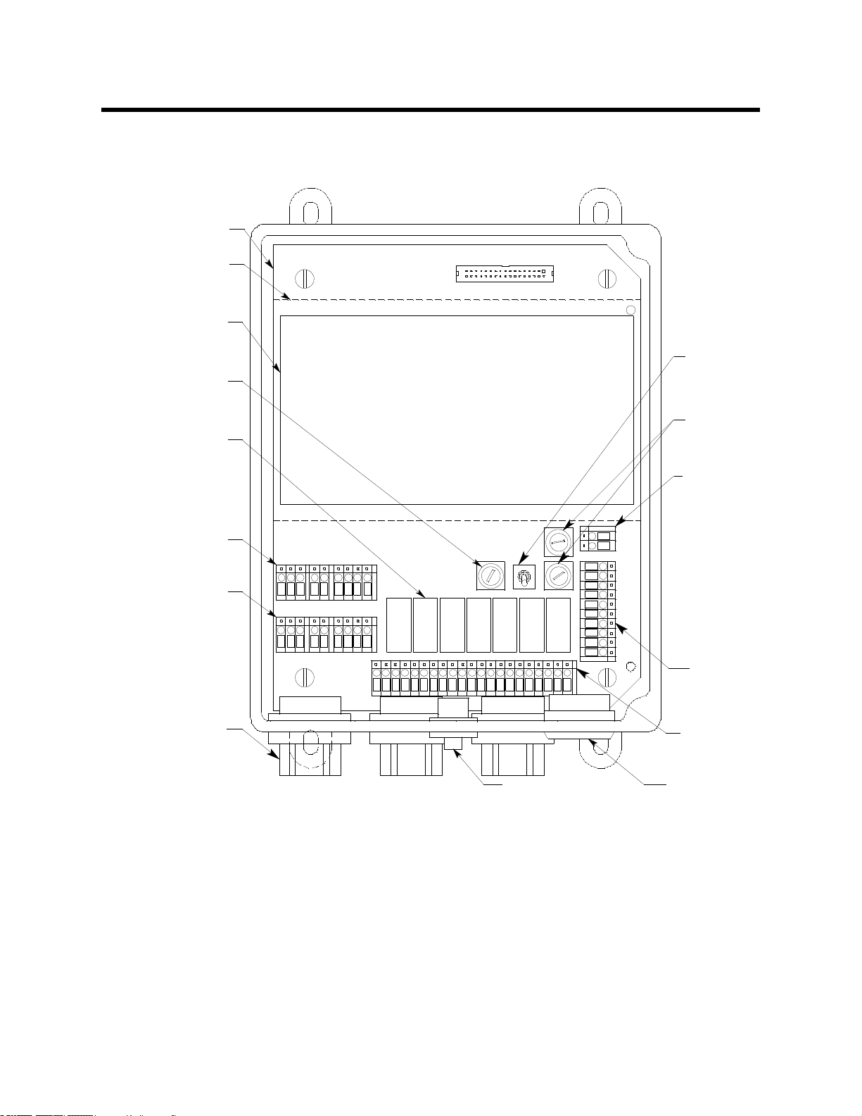
Internal Description
Power
Switch
AC Fuses
Controller
Terminal
Strip
Buzzer
Alarm
Terminal
Strip
Alarm Rel ays
(see Figure 3)
DC Fuse
Displ ay PCB
(see Figure 2)
Main PCB
Reset Switch
3/4" Conduit
Hu b , 3X
Detector/T ransm itter
Terminal Strip,
Channel 2
Detector/T ransm itter
Terminal Strip,
Channel 1
Power
Supply
AC In
Terminal
Strip
Figure 1. Beacon 200 Gas Monitor Component Location
This section describes the internal components of the Beacon 200.
Display Printed Circuit Board (PCB)
The display PCB is mounted to the power supply mounting plate which is in
turn mounted to the main PCB. The power supply mounting plate and main
PCB are described below. The display PCB includes the display, the status
lights, and the program buttons.
10 • Internal Description
Page 11
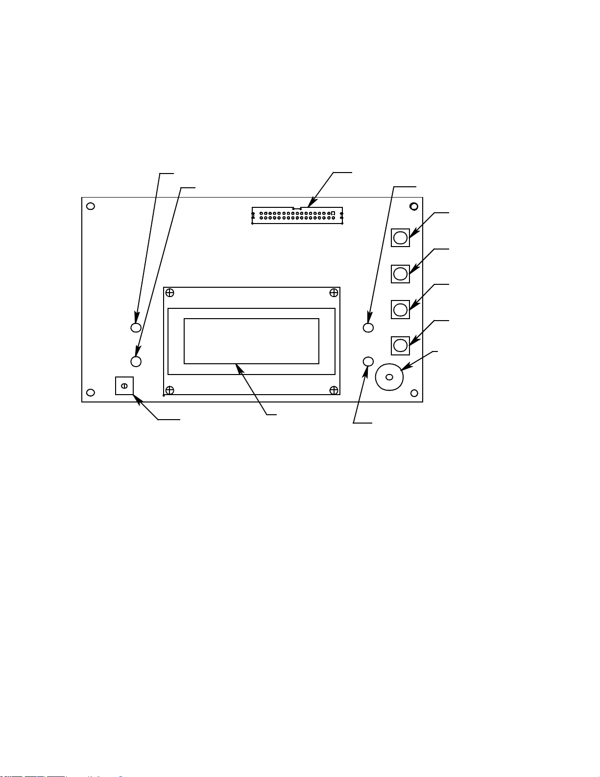
Display
ESCAPE
Button
UP/YES
Button
ENTER
Button
DOWN/NO
Button
Button Repeater
Buzzer
Display Screen
FAIL Light
PILOT Light
Display Cable Connector
J1
Display Contrast
Adjust Pot
ALARM 2 Light
ALARM 1 Light
Figure 2. Display Board Component Location
The display simultaneously indicates the channel number, current gas
reading, measuring unit, and target gas of all active channels.
The display also indicates messages, settings, and other data when you
are operating the instrument programs.
Internal Description • 11
Page 12

Status Lights
The Beacon 200 includes four status lights that indicate the current status
of the monitor. The status lights are to the left and right of the display (see
Figure 2).
• Pilot Light. The pilot light is on when the Beacon 200 is receiving
incoming power.
• Fail Light. The fail light turns on when the Beacon 200 is experiencing a
fail condition. A fail condition can be caused by a failure within the
Beacon 200 or detector head(s) wired to the Beacon 200. See Chapter
5, Maintenance, or the troubleshooting section in the applicable
detector head manual to respond to a fail condition.
• Alarm 1 Light. The alarm 1 light is on when the Beacon 200 is
experiencing an alarm 1 gas condition.
• Alarm 2 Light. The alarm 2 light is on when the Beacon 200 is
experiencing an alarm 2 gas condition.
Program Buttons
The Beacon 200 includes four program buttons that allow you to enter the
instrument programs, navigate through the programs, update instrument
and channel settings, and save changes to the program settings. When a
program button is pressed, a buzzer located on the display PCB beeps.
The program buttons are near the right edge of the display PCB (see
Figure 2).
Table 2: Beacon 200 Program Button Functions
Button Function
ESCAPE • Moves backward through the program menus
• Cancels changes you make in the program menus
• Enters the Channel Control and Setup program (press with the ENTER button)
UP/YES • Accepts the displayed setting and proceeds to the next setting
• Changes the displayed setting
• Enters the Calibration program (press with the ENTER button)
DOWN/NO • Allows you to update the displayed setting
• Changes the displayed setting
ENTER • Saves changes you make in the programs
• Enters the Channel Control and Setup program (press with ESCAPE button)
• Enters the Calibration program (press with the UP/YES button)
• Enters the Input Setup Program (press while flipping power switch to ON position)
12 • Internal Description
Page 13

Main PCB
The main PCB is mounted inside the housing. The power supply mounting
plate is mounted to the main PCB with four standoffs and the display PCB
is mounted to the power supply mounting plate with four standoffs. The
main PCB includes the terminal strips, relays, fuses, and power switch.
NOTE: If any of the Beacon 200’s channels have been set up for
hydrogen-specific LEL operation, the main PCB for that channel
or channels has been modified and can only be used with a
hydrogen-specific sensor. If you want to detect a different
combustible gas or use a different detector, the Beacon 200 must
be sent back to RKI Instruments, Inc. for modification.
Terminal Strips
The Beacon 200 includes four terminal strips for external wiring
connections. See “Wiring the Beacon 200 Gas Monitor” for detailed wiring
procedures.
• Detector/Transmitter Terminal Strips. Two detector/transmitter
terminal strips are located near the bottom left corner of the main circuit
board (see Figure 1). These two 9-point terminal strips facilitate wiring
connections to the detectors or transmitters. Although each terminal
strip can accommodate several different detector head models, only
one detector head at a time may be wired per channel. The top terminal
strip is for channel 1 and the bottom terminal strip is for channel 2.
• Alarm Terminal Strip. The alarm terminal strip is located along the
bottom edge of the main circuit board (see Figure 1). This 21-point
terminal strips facilitates wiring connections to external alarm devices
(horn, strobe, etc.). Terminals are provided for individual channel as
well as common alarm relay contacts.
• Controller Terminal Strip. The 10-point controller terminal strip is near
the lower right edge of the main circuit board (see Figure 1). The
controller terminal strip facilitates various internal and external wiring
connections. Table 3 lists the function of each terminal.
Table 3: Terminal Assignments for the Controller Terminal Strip
Terminal Connects to:
BAT -
BAT +
+ CH1 OUT + connection of 4 - 20 mA output, channel 1
- CH 1 OUT - connection of 4 - 20 mA output, channel 1
- connection from 24 VDC power source
+ connection from 24 VDC power source1 (or 24 V backup battery)
1
(or 24 V backup battery)
Internal Description • 13
Page 14

Table 3: Terminal Assignments for the Controller Terminal Strip (Continued)
Terminal Connects to:
+ CH2 OUT + connection of 4 - 20 mA output, channel 2
- CH2 OUT - connection of 4 - 20 mA output, channel 2
RESET (2) Reset switch (factory-wired)
BUZ-/BUZ+ Internal buzzer (factory-wired)
1
If DC power is used as the primary power source, do not make wiring connections to the AC terminal strip.
• AC In Terminal Strip. The AC in terminal strip is a 2-point terminal strip
located above the controller terminal strip (see Figure 1). It facilitates
wiring from the AC power source. Table 4 lists the function of each
terminal.
Table 4: Terminal Assignments for the AC In Terminal Strip
Terminal Connects to:
LINE Hot wire from AC power source.
NEUT Neutral wire from AC power source.
NOTE: The AC power source’s ground wire must be connected to the
ground stud. See “Connecting the AC Power Source” on page 20
for instructions.
Relays
The Beacon 200 includes four channel relays (two per channel) and three
common relays. Both sets of relays are single-pole, double-throw (SPDT)
and are rated for 10 amps at 250 VAC (resistive).
NOTE: You can select normally energized (NE) or normally de-energized
(NDE) settings for each channel in the Channel Control and Setup
program. This section describes the default setting: normally deenergized.
The alarm 1 and alarm 2 common relays are factory-set as NDE
and the fail common relay is factory-set as NE. The alarm 1, alarm
2, and fail common relays’ NE/NDE settings are not useradjustable.
• Channel Relays. The four channel relays are above the alarm terminal
strip (see Figure 1). These relays are dedicated to specific channels
and alarm levels.
14 • Internal Description
Page 15
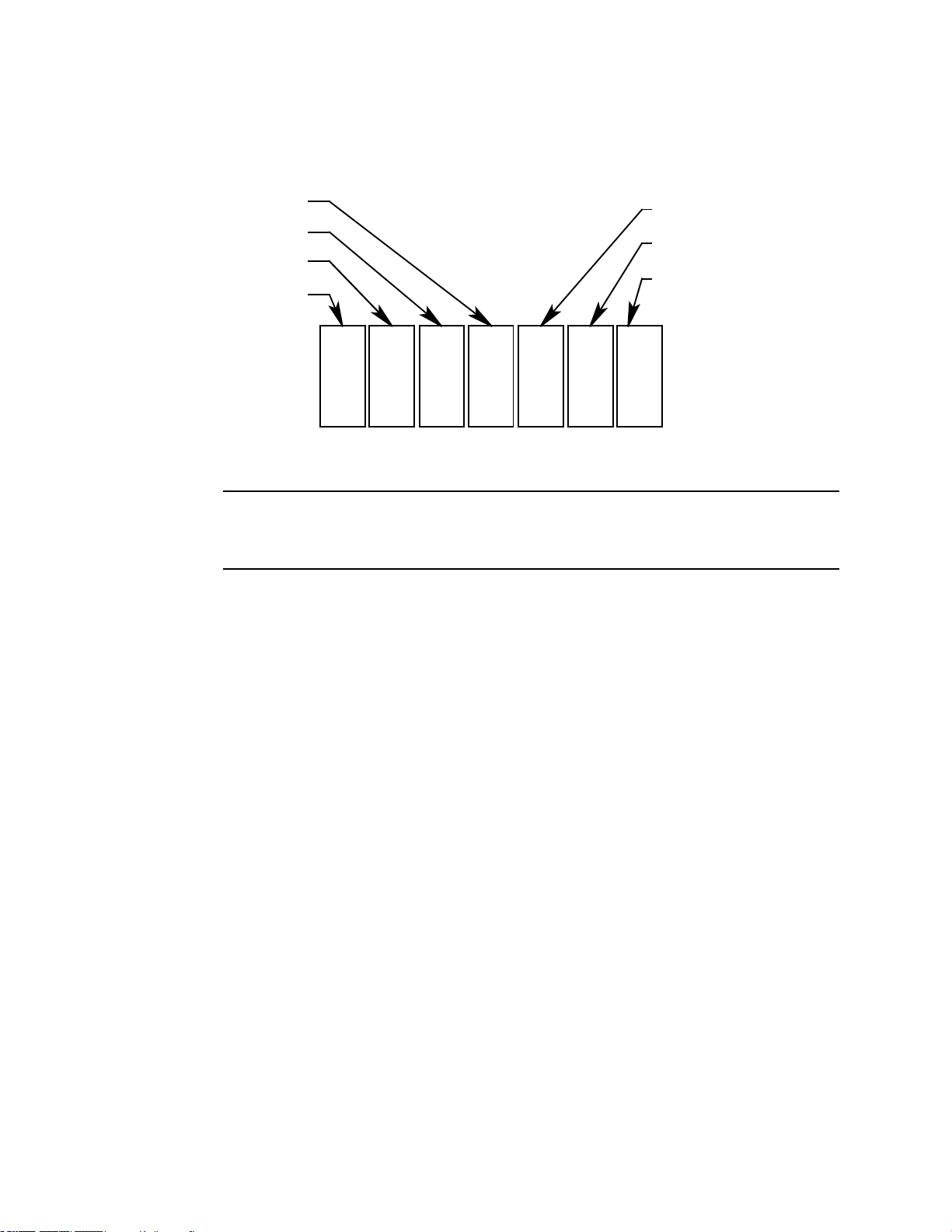
For example, the channel 1, alarm 1 relay energizes if channel 1
K5 K6 K7
Channel 2, Alarm 1
Channel 1, Alarm 2
Channel 1, Alarm 1
K1 K2 K3
Common Alarm 1
Common Alarm 2
Common Fail
K4
Channel 2, Alarm 2
Figure 3. Beacon 200 Channel Relay Allocation
recognizes an alarm 1 condition. Figure 3 below illustrates the
allocation of the channel relays.
NOTE: The alarm 2 channel relays may be set to operate as individual
channel fail relays. See the Configure Channel Settings section of
Chapter 5 for instructions.
• Common Relays. The three common relays, alarm 1, alarm 2, and fail,
are to the left of the controller terminal strip (see Figure 1). These relays
are common for both channels.
For example, the alarm 1 common relay energizes if either channel 1 or
channel 2 recognizes an alarm 1 condition.
Fuses
There are three fuses that are used in the Beacon 200. Two of them are AC
fuses and one of them is a DC fuse.
• AC Fuses. The two fuses located directly to the left of the controller
terminal strip are the AC fuses. They cut off the incoming AC power in
the event of a short circuit or other electrical fault which causes a high
current draw in the Beacon 200. They are housed in vertical fuse
holders and are held in the holder by a quarter turn cover. They are
labelled as F2 (top fuse) and F3 (bottom fuse) on the PCB silk-screen
and are rated to 3 A, 250 V, 1/4 x 1 1/4”, fast acting.
• DC Fuse. The fuse located to the left of the power switch is the DC
fuse. It cuts off incoming DC power in the event of a short circuit or
other electrical fault which causes a high current draw in the Beacon
200. It is also housed in a vertical fuse holder and is held in the holder
by a quarter turn cover. It is labelled as F1 on the PCB silk-screen and
is rated to 6A, 250 V, 1/4 x 1 1/4”, fast acting.
Internal Description • 15
Page 16

Power Switch
The power switch is located above the relays and in between the AC and
DC fuses (see Figure 1). The power switch turns the incoming AC power
source on and off at the Beacon 200. When the switch is up, the power
switch is on.
NOTE: The DC power input has no on/off switch and is not affected by the
position of this switch.
Power Supply
The power supply is mounted to the power supply mounting plate which is
located behind the display PCB. The power supply mounting plate is
mounted to the main PCB with four standoffs. The power supply receives
the AC input from the external power source and converts it to a DC
voltage that is usable by the Beacon 200 circuitry.
16 • Internal Description
Page 17

Chapter 3: Installation and Start Up
Overview
This chapter describes procedures to mount the Beacon 200 Gas Monitor,
make wiring connections to the monitor, and start up the monitor.
WARNING: Perform all installation and start-up procedures in a
“fresh air” environment (known to be free of combustible
gas, toxic gas, and of normal oxygen content). The
Beacon 200 is not in operation as a gas monitoring
system until the start-up procedure is complete.
Mounting the Beacon 200 Gas Monitor
WARNING: Only aut horized and properly trained personnel should
perform any mounting procedures.
Perform the following procedure to install the Beacon 200 at the mounting
site.
1. Select the mounting site. When you select the mounting site consider
the following factors:
• Is an AC or DC power source available?
• Is there enough room to open the housing door and make wiring
connections through the conduit hubs at the bottom of the housing?
• Are the display screen and status lights visible?
2. Close and latch the housing door.
3. Position the monitor on a vertical surface at eye level (4 1/2 to 5 feet
from the floor).
4. The Beacon 200 is shipped with the mounting feet positioned behind
the housing. Loosen the screws that secure the feet to the housing,
rotate the feet to their mounting position (as shown in Figure 4), then
tighten the screws.
Overview • 17
Page 18
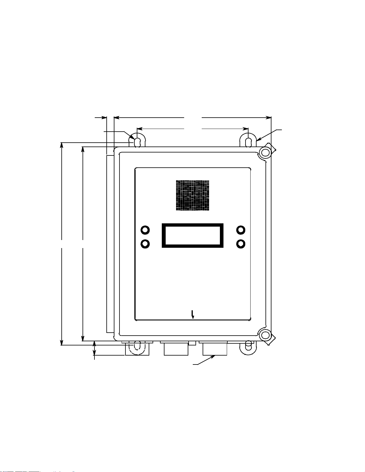
5. Insert 1/4 in. or 5/16 in. screws through the slots in the mounting feet at
Mounting
Feet, 4X
Ø .38 x .50 slot, 4X
.41
6.00
8.50
ALARM 2
PILOT
FAIL
RESET
BEACON 200
GAS MONITOR
ALARM 1
10.5010.94
3/4 " Conduit Hub(3)
.80
Figure 4. Beacon 200 Gas Monitor Outline and Mounting Dimensions
each corner of the housing to secure the housing to the mounting
surface (see Figure 4).
6. Each of the door clamps has a feature for locking device installation. A
locking device that requires a tool to unlock must be installed in each
door clamp.
18 • Mounting the Beacon 200 Gas Monitor
Page 19

NO T E: A C ground
connec tion is m ade
to ground stud in
lower rig h t corn e r
of c i rcuit board.
115V/220V~
+
COM-A1 COM-FAILCOM-A2
BAT
CH2-A1CH1-A2
Reset Switch
(Fa c tory W i re d)
Buzze r
(Fa c tory W i re d)
Oxygen
Detecto r
Channel 1 Recorder
1K M axImpedance
BUZ
Green
+
White
+S
LEL
OXYG E NAMP /P REA M P
NO NC C NO NC CNO NC CNO NC C NO NC C
CHANNEL 2
+S +
LEL
OXYG E NAMP /P REA M P
Typica l Detector/Transmitter
Terminal Strip Wiring
Onl y o ne d et ector or t ransmi tterc a nbe
wired t o Ch1 orC h2 at a time. S ee d etector
head w iring d iagr am for specific wi ring.
BUZ +
RESET
RESET
CH2-A2
Typical Ala rm Re lay TerminalStrip Wiring
BAT +
AC
In Terminal Strip Wiring
CH 1
OUT
Line (H ot)
Neutral
Black
LEL Detector
Contact Rating o f 10 Amps at 115/220V~
Resistive o r 10A @ 3 0V R esistive for E ach
SetofAlarmRelayContacts.
NO NC C
RW G B
Green
FB ( 4-20 mA )
2-W ire 4-20 ma
Transm itter
+24V
3-W ire 4-20 ma
Transm itter
- DC GROUND
FB ( 4-20 mA )
RW G B
+24V
Alarm Devices
Channel 2 Recorder
1K M axImpedance
CHANNEL 1
CH 2
OUT
+
White
Red
NO NC C
Controlle r Term inal
Strip Wiring
24 V
CH1-A1
4- 20mAO ut
4- 20mAO ut
Alarm Device
Power
Figure 5. Beacon 200 Gas Monitor General External Wiring Diagram
Mounting the Beacon 200 Gas Monitor • 19
Page 20

Wiring the Beacon 200 Gas Monitor
WARNING: Only aut horized and properly trained personnel should
perform any wiring procedures.
This section describes procedures to connect the AC power source, DC
power source, external alarm(s), recorder, and detector head(s). See
Figure 5 for a general wiring diagram of all external wiring to the Beacon
200.
WARNING: Make all connections to the Beacon 200 before you plug
in or connect mains power. Before you make any wiring
adjustments, always verify that mains power to the
Beacon 200 is turned off or disconnected.
Routing Wiring Into the Beacon 200 Housing
Wiring must be brought into the housing through one of the three factoryinstalled conduit hubs on the bottom of the housing.
Do not
200 housing and routing wiring through holes not factory drilled will void the
warranty and could result in:
• Damage to internal components from the drilling process.
• Moisture damage to internal components from poorly sealed holes.
• Unpredictable Beacon 200 behavior due to EMI/RFI interference
• Possible shorting of Beacon 200 components due to wires routed
drill into the Beacon 200 housing for any reason. Drilling the Beacon
caused by wires routed across the PCBs.
across the PCBs.
Connecting the AC Power Source
NOTE: If you are using DC power as the primary power source, go to the
next section, “Connecting the DC Power Source.”
The AC In terminal strip will accept 24 - 14 AWG wire. For 115 VAC
connection, select wire that is rated to a minimum of 80°C, 0.75 A, and
150V. For 220 VAC connection, select wire that is rated to a minimum of
80°C, 0.5 A, and 250 V. When selecting wire, be sure to meet the local
electrical code.
A certified switch or circuit breaker must also be installed in the AC line. For
20 • Wiring the Beacon 200 Gas Monitor
Page 21

115 VAC connection, the switch or circuit breaker must be rated to 115
Line (H ot)
Neutral
115 V/220 V ~ ± 10%,
50/60 Hz
Disconnect D evice
AC In Terminal Strip
Figure 6. AC Power Wiring
VAC, 50/60 Hz, and 0.5 A. For 220 VAC connection, the switch or circuit
breaker must be rated to 220 VAC, 50/60 Hz, and 0.3 A.
Perform the following procedure to connect the AC power source to the
Beacon 200.
WARNING: Verify that mains power to the Beacon 200 is turned off or
disconnected before you continue with this procedure.
1. Turn off or disconnect mains power to the Beacon 200.
2. Open the housing door, then place the power switch in the OFF
position.
3. Install an appropriately rated cable bushing or conduit to the right-most
conduit hub on the bottom of the Beacon 200 housing.
CAUTION: Only use the three facto ry installed condui t hubs on the bottom
of the housing for wire entry into the housing. Do not drill the
housing for any reason. See “Routing Wiring Into the Beacon
200 Housing” on page 20 for more information.
4. Locate the 2-point AC In terminal strip (see Figure 1). The terminals
are labelled LINE and NEUT.
5. Guide the AC power cord or wires through the right-most conduit hub
on the bottom of the Beacon 200 housing.
CAUTION: Do not route power and det ector head wiring through the same
conduit hub. The p ower wiring may di sr upt th e transmission of
the detector head signal to the monitor.
6. Connect the line (hot) and neutral AC wires to the AC power terminal
strip as shown in Figure 6.
Wiring the Beacon 200 Gas Monitor • 21
Page 22

7. Connect the ground wire to the unused crimp terminal that is factory
installed at the base of the ground stud.
a. Remove all installed connections (from conduit hubs and power
supply).
b. Remove the bottom lug.
c. Crimp the ground wire to the lug.
d. Reinstall the lug.
e. Reinstall all of the other ground connections (from conduit hubs and
power supply).
WARNING: Follow this grounding procedure to maintain the CSA
classification of the Beacon 200.
Connecting the DC Power Source
WARNING: Verify that mains power to the Beacon 200 is turned off or
disconnected before you continue with this procedure.
DC power may be used as a primary power source. If DC power
(connected to the BAT terminals on the controller terminal strip) is the
primary power source, DO NOT connect AC power to the AC In terminal
strip.
A 24 VDC battery (connected to the BAT terminals on the controller
terminal strip) may also be used as a backup power source if AC power
(connected to the AC In terminal strip) is the primary power source.
The controller terminal strip will accept 24 - 14 AWG wire. Select wire that
is rated to a minimum of 80°C, 0.75 A, and 150V. When selecting wire, be
sure to meet the local electrical code.
WARNING: The BAT terminals on the controller terminal strip are
only intended for connecting a battery or a 24 VDC supply
to the Beacon 200. Do not connect any horns or strobes
to the BAT terminals on the controller terminal strip.
1. Turn off or disconnect mains power to the Beacon 200.
2. Open the housing door, then place the power switch in the OFF
position. Locate the DC power terminals on the controller terminal strip
(see Figure 1). They are labelled BAT - and BAT +
3. Install an appropriately rated cable bushing or conduit to one of the
unused conduit hubs on the bottom of the Beacon 200 housing.
22 • Wiring the Beacon 200 Gas Monitor
Page 23

CAUTION: Only use the three facto ry installed condui t hubs on the bottom
24 VDC ± 2.5 VDC
+
BAT
BAT +
Controller Terminal Strip
Figure 7. DC Power Wiring
of the housing for wire entry into the housing. Do not drill the
housing for any reason. See “Routing Wiring Into the Beacon
200 Housing” on page 20 for more information.
4. Guide a DC power cord or wires through the selected conduit hub.
CAUTION: Do not route power and det ector head wiring through the same
conduit hub. The p ower wiring may di sr upt th e transmission of
the detector head signal to the monitor.
CAUTION: When a batter y is used as backup power, the Beacon 200
trickle charges the battery. Do not use a non-rechargeable
battery as backup power. Use RKI backup battery 49-8102RK
or an appropriately rate d re cha rg ea bl e le ad acid type battery.
5. Connect the DC wires to the controller terminal strip as shown in
Figure 7.
NOTE: If a 24 VDC battery is used as a backup power source, as long as
AC power is on the Beacon 200 will keep a trickle charge on the
battery to maintain its charge. If AC power is interrupted, the
Beacon 200 will operate from the DC backup battery until the
battery voltage drops to 21.5 volts or less, or until AC power is
restored. Battery recharge time will vary depending on how much
the battery was drained.
Wiring the Beacon 200 Gas Monitor • 23
Page 24

Connecting External Alarms
The alarm terminals will accept 24 - 14 AWG wire. Select wire that is rated
to a minimum of 80°C, up to 10 A depending on the device being powered,
and up to 250V depending on the device being powered.
Perform the following procedure to connect external alarm devices to the
Beacon 200.
NOTE: The alarm terminal strip includes terminals for channel alarms
and common alarms. Channel alarms are activated by one
particular channel. Common alarms are activated by either of the
two channels.The example used in this procedure describes
connecting an external alarm device to one of the channel alarm
terminals: the channel 1, alarm 1 terminals.
WARNING: Do not connec t external alarms to the BAT terminals on
the controller terminal strip.
1. Turn off or disconnect mains power to the Beacon 200.
2. Open the housing door, then place the power switch in the OFF
position. Locate the alarm terminal strip (see Figure 1).
3. Install an appropriately rated cable bushing or conduit in an unused
conduit hub on the bottom of the Beacon 200 housing.
CAUTION: Only use the three facto ry installed condui t hubs on the bottom
of the housing for wire entry into the housing. Do not drill the
housing for any reason. See “Routing Wiring Into the Beacon
200 Housing” on page 20 for more information.
4. Guide the wiring of the external alarm device through the selected
conduit hub on the bottom of the Beacon 200 housing.
CAUTION: Do not route the external alarm wiring and detector head
wiring through the same conduit hub. The external alarm
wiring may disrupt the transmission of the detector signal to
the Beacon 200.
24 • Wiring the Beacon 200 Gas Monitor
Page 25

5. Connect the leads from the external alarm device and power to the
Beacon 200 Alarm
Terminal Strip
-(N)
+ (H)
CH1-A1
NO NC C
External Alarm
Device
External Power
Source
Figure 8. Typical External Alarm Wiring
alarm terminals as shown in Figure 8.
6. Repeat steps 3 through 5 for additional external alarm devices.
Connecting a Recorder
The recorder output terminals will accept 24 - 14 AWG wire. Select wire
that is rated to a minimum of 80°C, 0.2 A, and 150V.
Perform the following procedure to connect an analog recording device to
the Beacon 200. The output at the recorder output terminals is a 4 - 20 mA
signal that is proportional to the detection range of the applicable detector
head.
1. Turn off or disconnect mains power to the Beacon 200.
2. Open the housing door, then place the power switch in the OFF
position. Locate the recorder output terminals on the controller terminal
strip (see Figure 1).
3. Install an appropriately rated cable bushing or conduit in an unused
conduit hub on the bottom of the Beacon 200 housing.
CAUTION: Only use the three facto ry installed condui t hubs on the bottom
of the housing for wire entry into the housing. Do not drill the
housing for any reason. See “Routing Wiring Into the Beacon
200 Housing” on page 20 for more information.
4. Guide the wiring from the recording device through the selected
conduit hub on the Beacon 200.
Wiring the Beacon 200 Gas Monitor • 25
Page 26

5. Connect the wires from the recording device to the recorder output
+
CH2
OUT
+
CH1
OUT
+
Recording Device
#2, 1Kohm Max
Impedance
Recording Device
#1, 1Kohm Max
Impedance
+
Figure 9. Recorder Output Wiring
terminals as shown in Figure 9.
Connecting RKI Detector Heads
The detector/transmitter terminals will accept 24 - 14 AWG wire. Select
wire that is rated to a minimum of 80°C, 0.75 A, and 150V.
26 • Wiring the Beacon 200 Gas Monitor
Perform the following procedure to connect an RKI detector head to the
Beacon 200.
NOTE: If any of the Beacon 200’s channels have been set up for
hydrogen-specific LEL operation, that channel or channels can
only be used with a hydrogen-specific sensor. If you want to detect
a different combustible gas or use a different detector, the Beacon
200 must be sent back to RKI Instruments, Inc. for modification.
1. Turn off or disconnect mains power to the Beacon 200.
2. Open the Beacon 200 door and place the power switch in the off
position.
3. See the detector head instruction manual for instructions on how to
connect wires to the detector head.
4. Install an appropriately rated cable bushing or conduit in an unused
conduit hub on the bottom of the Beacon 200 housing.
CAUTION: Only use the three facto ry installed condui t hubs on the bottom
of the housing for wire entry into the housing. Do not drill the
housing for any reason. See “Routing Wiring Into the Beacon
200 Housing” on page 20 for more information.
Page 27

5. Route the wires in conduit or shielded cable from the detector head
through the selected conduit hub into the Beacon 200. See Table 5
below for wire size and distance guidelines.
Unshielded twisted pair cable in conduit or shielded twisted pair cable
is recommended for all the direct connect detector heads. For the LEL
detector, pair the R & B wires and the W & G wires. Shielded cable or
wires in conduit are recommended for the 2-wire and 3-wire 4 - 20 mA
transmitters.
6. Connect the wires from the detector head to the appropriate detector/
transmitter terminals. The top detector terminal strip is for channel 1
and the bottom one is for channel 2. See the detector head instruction
manual for controller terminal connections.
CAUTION: Do not route power and det ector head wiring through the same
conduit hub. The p ower wiring may di sr upt th e transmission of
the detector head’s to the Beacon 200.
Table 5: Wire Size Guidelines for RKI Detector Head Wiring
Number of
Detector Head Type
Direct Connect LEL 4 500 ft. 1,000 ft. 2,000 ft.
Direct Connect Oxygen 2 500 ft. 1,000 ft. 2,000 ft.
Direct Connect H2S 2 500 ft. 1,000 ft. 2,000 ft.
Direct Connect CO 2 500 ft. 1,000 ft. 2,000 ft.
Direct Connect Cl2 2 500 ft. 1,000 ft. 2,000 ft.
Direct Connect SO2 2 500 ft. 1,000 ft. 2,000 ft.
2-Wire 4 - 20 mA Transmitter 2 2,500 ft. 5,000 ft. 8,000 ft.
3-Wire 4 - 20 mA Transmitter 3 2,500 ft. 5,000 ft. 8,000 ft.
Wires to
Controller
Max Distance
to Controller
w/18 Gauge
Wire
Max Distance
to Controller
w/16 Gauge
Wire
Max Distance
to Controller
w/14 Gauge
Wire
Connecting User-Supplied 4 - 20 mA Transmitters
The Beacon 200 may be used with a user supplied 2-wire or 3-wire 4 - 20
mA transmitter which runs on 24 VDC. When this is done, the following
Beacon 200 parameters are normally setup at RKI Instruments: unit of
measure, item name, and full scale. For example, “PSI AIR” with a full
scale of 10 PSI.
The detector/transmitter terminals will accept 24 - 14 AWG wire. Select
wire that is rated to a minimum of 80°C, 0.75 A, and 150V.
Wiring the Beacon 200 Gas Monitor • 27
Page 28

Perform the following procedure to connect a 4 - 20 mA transmitter, which
AMP/PREAMP OXYGEN
+ + S
LEL
R W G B
2-Wire 4-20 ma
Transmitter
+ 24 VDC
FB (4-20 mA)
OXYGEN
2-Wire Connection
+ S
AMP/PREAMP
+
3-Wire 4-20 ma
Transmitter
3-Wire Connection
+ 24 VDC
FB (4-20 mA)
-
(DC GROUND)
LEL
R W G B
Figure 10. Generic 4 to 20 mA Transmitter Output Wiring
you supply, to the Beacon 200.
1. Turn off or disconnect mains power to the Beacon 200.
2. Open the Beacon 200 door and turn off the power switch.
3. See the transmitter’s instruction manual for instructions on how to
connect wires to the transmitter.
4. Install an appropriately rated cable bushing or conduit in an unused
conduit hub on the bottom of the Beacon 200 housing.
CAUTION: Only use the three facto ry installed condui t hubs on the bottom
of the housing for wire entry into the housing. Do not drill the
housing for any reason. See “Routing Wiring Into the Beacon
200 Housing” on page 20 for more information.
5. Route the wires from the transmitter through the selected conduit hub
into the Beacon 200.
6. Connect the wires from the transmitter to the appropriate detector/
transmitter terminals. The top detector terminal strip is for channel 1
and the bottom one is for channel 2. See the transmitter instruction
manual for controller terminal connections. Figure 10 below illustrates
typical transmitter wiring connections.
CAUTION: Do not route power and transmitter wiring through the same
conduit hub. The p ower wiring may di sr upt th e transmission of
the transmitter’s signal to the Beacon 200.
28 • Wiring the Beacon 200 Gas Monitor
Page 29

Starting Up the Beacon 200 Gas Monitor
WARNING: Only aut horized and properly trained personnel should
perform any startup procedures.
Perform the following procedure to place the Beacon 200 into normal
operation.
1. Complete the mounting and wiring procedures described earlier in this
chapter.
2. Complete all installation procedures described in the detector head or
user supplied 4 - 20 mA transmitter instruction manual.
3. Verify that all wiring connections are correct and secure and that the
Beacon 200’s power switch is in the OFF position.
4. Turn on or connect mains power to the Beacon 200.
5. Place the Beacon 200’s power switch in the ON position. RKI
INSTRUMENTS BEACON 200 appears on the display for a few
seconds, then WARMING UP appears for each active channel. The
warm-up period will last for one minute.
NOTE: To prevent unwanted alarms during warm up, the alarm circuits
are not active while the WARMING UP message is displayed.
6. Verify that the PILOT light is on. If the PILOT light is not on, see the
troubleshooting guide in Chapter 5, Maintenance.
7. Perform the start-up procedure for each detector head or user supplied
4 - 20 mA transmitter as described in the detector head or transmitter
instruction manual
Starting Up the Beacon 200 Gas Monitor • 29
Page 30

Chapter 4: Operation
1
2
0
20.9
%
L
E
%
CH4
Oxy
L
:
:
g
e
n
Overview
This chapter describes the Beacon 200 Gas Monitor in normal operation.
This chapter also describes the Beacon 200 in alarm 1, alarm 2, and fail
conditions and suggests response to these conditions.
Normal Operation
Normal operation is defined as follows:
• The start-up procedure is complete.
• The Beacon 200 is not indicating an alarm 1, alarm 2, or fail condition.
• The Beacon 200 is not running the Channel Control & Setup or
Calibration Programs.
During normal operation, the Beacon 200 simultaneously displays the
current gas reading, unit of measure, and target gas for each active
channel.
The PILOT light is on during normal operation indicating that the Beacon
200 is receiving incoming power.
30 • Overview
Page 31

Recorder Output Operation
The output at the recorder output terminals is a 4 - 20 mA signal for each
active channel that is proportional to the detection range of the channel. A
channel that is set as CHANNEL NOT USED or CHANNEL DISABLED in
the Channel Control & Setup Program (see Chapter 5) has an output of 0
mA.
There are several special circumstances where the recorder output will
behave as follows:
• When a channel is in WARMUP after the Beacon 200 is turned on, the
recorder output will be at 4 mA for all channel types except oxygen. For
oxygen channels, the output will be 17.4 mA while in WARMUP.
• If the Beacon 200 is being powered by a battery and is in low battery
alarm, the recorder output for each channel will be 0 mA.
• When a channel is added or a channel type changed, the display will
indicate NEEDS CALIBRATION for that channel when the Beacon 200
is first turned on and will continue to indicate this until the channel is
calibrated. In this situation, the recorder output will be 3.2 mA until the
channel is calibrated.
• If a channel goes into a fail condition, the recorder output will be 0 mA.
• If you enter any of the instrument programs, such as the Calibration
Program, the recorder output will hold at the value it was at when you
entered the program was entered until you return to normal operation.
Recorder Output Operation • 31
Page 32

Alarm Indications
This section describes the Beacon 200 in alarm 1, alarm 2, and fail
conditions and suggests response to these conditions. Table 6 below lists
the alarm indications for each condition.
NOTE: The Beacon 200 includes alarm on and alarm off delay settings for
each channel and level of gas alarm. The alarm indications
described in this section operate according to the factory set delay
settings. See the Configure Channel Settings Menu section of
Chapter 5 for all the factory settings.
Table 6: Visual and Audible Alarm Indications
Condition Cause Visual Indication(s)
Alarm 1
Alarm 2
Fail • Disconnected or misconnected
Low Battery
*
*2If DC power is used as primary or backup power source.
1
1
1
If the Beacon 200 is in both an alarm 1 and an alarm 2 condition, both alarm lights are on and the display
alternates between the gas reading and the ALARM-1 ALARM-2 messa ge.
Increasing (decreasing for O2) gas
reading at or above the alarm 1
setpoint
Increasing gas reading at or above
the alarm 2 setpoint
detector wiring
• Display reading below -10% of full
scale or lower
• Defective components
2
No AC power and DC power source
(primary or backup) less than 21.5
volts.
• ALARM 1 light is on
• Gas reading flashes and
alternates with ALARM-1
message
• ALARM 2 light is on
• Gas reading flashes and
alternates with ALARM-2
message
• FAIL light is on
• FAIL message flashes in place
of gas reading
• FAIL light is on
• SUPPLY VOLTAGE IS TOO
LOW LOW POWER
STANDBY message and actual
voltage of incoming DC power
Pulsing tone
Pulsing tone
Steady tone
None
Audible
Indication
NOTE: You can select normally energized (NE) or normally de-energized
(NDE) channel relay settings in the Channel Control & Setup
menu. The following sections describe the default setting for the
channel relays which is NDE.
Common alarm 1 and alarm 2 relays are factory-set as NDE, and
the common fail relay is factory set as NE. The common relays’
NE/NDE settings are not user-adjustable.
32 • Alarm Indications
Page 33

Alarm 1 Condition
This section describes the audible and visual indications for an alarm 1
condition and suggests response to an alarm 1 condition.
Alarm 1 Condition Indications
When the gas reading of an active channel reaches the alarm 1 setpoint,
the Beacon 200 senses an alarm 1 condition. The Beacon 200 alerts you to
an alarm 1 condition as follows:
• The ALARM 1 light turns on.
• The gas reading in alarm 1 condition flashes and alternates with the
ALARM-1 message.
• The buzzer sounds a pulsing tone.
• The common alarm 1 relay energizes.
• The applicable alarm 1 channel relay energizes.
Responding to an Alarm 1 Condition
This section suggests response to an alarm 1 condition.
1. Follow your established procedure for a low level combustible or toxic
gas condition or a decreasing oxygen content condition.
2. Oxygen alarms are self-resetting and will automatically clear when the
oxygen rises above the alarm 1 setpoint.
3. Alarms for all other gas types are latching. After the gas reading falls
below the alarm 1 setpoint, press the reset switch to reset the alarm 1
circuit. Resetting the alarm 1 circuit silences the buzzer, turns off the
ALARM 1 light, resets the channel display, and de-energizes the
common and channel alarm 1 relays.
NOTE: To silence the buzzer while in an alarm 1 condition, press the
reset switch.
You cannot de-energize the alarm 1 relays until the gas reading
falls below (above for oxygen) the alarm 1 setpoint.
Alarm Indications • 33
Page 34

Alarm 2 Condition
This section describes the audible and visual indications for an alarm 2
condition and suggests response to an alarm 2 condition.
Alarm 2 Condition Indications
When the gas reading of an active channel reaches the alarm 2 setpoint,
the Beacon 200 senses an alarm 2 condition. The Beacon 200 alerts you to
an alarm 2 condition as follows:
• The ALARM 2 light turns on.
• The gas reading in alarm 2 condition continues to flash and alternates
with the ALARM-2 messages.
• The buzzer sounds a pulsing tone.
• The common alarm 2 relay energizes.
• The applicable alarm 2 channel relay energizes.
Responding to an Alarm 2 Condition
This section suggests response to an alarm 2 condition.
1. Follow your established procedure for a high level combustible or toxic
gas condition or an increasing oxygen content condition.
2. Oxygen alarms are self-resetting and will automatically clear when the
oxygen rises above the alarm 2 setpoint.
3. Alarms for all other gas types are latching. After the gas reading falls
below the alarm 2 setpoint, press the reset switch to reset the alarm
circuit. Resetting the alarm circuit turns off the ALARM 2 light, and deenergizes the common and channel alarm 2 relays.
NOTE: To silence the buzzer while in an alarm 2 condition, press the
reset switch.
You cannot de-energize the alarm 2 relays until the gas reading
falls below the alarm 2 setpoint.
Fail Condition
This section describes the audible and visual indications for a fail condition
and suggests response to a fail condition.
Fail Condition Indications
The Beacon 200 senses a fail condition for any of the following:
• The detector head wiring to the Beacon 200 is disconnected or
34 • Alarm Indications
Page 35

incorrectly connected.
• The detector head’s detector is disconnected or incorrectly connected.
• The display reading is -10% of full scale or lower.
• The Beacon 200 or detector head is malfunctioning.
When the Beacon 200 senses a fail condition, it alerts you as follows:
• The FAIL light turns on.
• The gas reading for the failing channel is replaced by the FAIL
message.
• The buzzer sounds a steady tone.
• The common fail relay de-energizes.
NOTE: If you elected to use the channel’s alarm 2 relay as an individual
fail relay in the Channel Control & Setup menu, the relay deenergizes in a fail condition. See the Channel Control & Setup
section of Chapter 5 for a description of this setting.
Responding to a Fail Condition
This section suggests response to a fail condition.
1. Verify that the detector head wiring to the Beacon 200 is correctly and
securely connected.
2. Verify that the detector head’s detector is correctly and securely
connected.
3. See the troubleshooting guide in the detector head instruction manual.
Low Battery Condition
This section describes the audible and visual indications for a low battery
condition and suggests response to a low battery condition. This condition
only applies when DC power is used as a primary or backup power source.
NOTE: When a 24 VDC battery is used as a backup power source, the
Beacon 200 keeps the battery charged by providing a trickle
charge from the AC power source. If AC power is interrupted, the
Beacon 200 will operate from the DC backup battery until the
battery voltage drops to 21.5 volts or less, or until AC power is
restored.
Alarm Indications • 35
Page 36

Low Battery Condition Indications
The Beacon 200 senses a low battery condition when:
• AC power is disconnected, misconnected, or interrupted
AND
• the DC power source is 21.5 volts or less
When the Beacon 200 senses a low battery condition, it alerts you as
follows:
• The FAIL light turns on.
• The top display screen displays the SUPPLY VOLTAGE IS TOO LOW,
LOW POWER STANDBY message and the actual voltage of incoming
DC power.
Responding to a Low Battery Condition
This section suggests response to a low battery condition.
• If DC power is the primary power source:
1. For a temporary DC power source, disconnect primary DC power at
the Beacon 200, then connect a 24 VDC backup battery.
2. Determine and correct the cause of primary DC power loss.
When the DC power source rises above 22.0 volts, the Beacon 200
begins the warm up process.
• If DC power is the backup power source:
1. Replace or recharge the 24 VDC backup battery to resume backup
power capability.
2. Determine and correct the cause of primary AC power loss.
When backup DC or primary AC power is restored, the Beacon 200
begins the warm up process. When AC power is restored, the Beacon
200 charges the backup battery until it is fully recharged. Charge time
varies depending on the battery size and how much the battery was
depleted. Once the battery is fully charged, the Beacon 200 reverts to
a trickle charge to maintain the battery charge.
36 • Alarm Indications
Page 37

Viewing & Resetting Min/Max Readings
The reset switch may be used to view and reset the minimum and
maximum gas readings for the active channel(s).
1. While the Beacon 200 is in normal operation, press and hold the reset
switch button for 3 seconds.
2. The display will indicate MIN / MAX Display Press RESET when
done viewing . . . for 5 seconds before displaying the minimum and
maximum readings for the active channel(s). The minimum reading is
on the left and the maximum is on the right side of the display for each
channel.
3. Press and release the reset switch button to exit the min/max screen.
The display will indicate To RESET Min/MAX values Press and HOLD
RESET Button for 10 seconds and then return to normal operation.
• To return to normal operation without resetting the minimum and
maximum readings, do not press the reset switch button and allow
the unit to return to normal operation.
• To reset the minimum and maximum readings, before the unit
returns to normal operation press and hold the reset switch button
until the display indicates Min/Max Values Have Been Reset.
Release the reset switch button.The unit will then return to normal
operation.
Viewing & Resetting Min/Max Readings • 37
Page 38

Chapter 5: Channel Control and Setup Program
Overview
The Channel Control & Setup Program allows viewing of and changes to
instrument setup parameters. It is accessed using the program buttons.
The Channel Control & Setup Program includes three menus as described
in Table 7.
Table 7: Channel Control & Setup Program Menus
Menu Function
Enable/Disable Channel(s) Configures channels as enabled, disabled, or not used
Configure Channel Settings Configures alarm settings, noise filter setting, and zero
suppression setting for each channel
View System Information Displays the firmware version number and the instrument
operating voltage
To enter the Channel Control & Setup Program, simultaneously press and
hold the ESCAPE and ENTER buttons for approximately 5 seconds.
The Channel Control & Setup Program menu includes a 5-minute time-out
feature. If you do not press a button for 5 minutes, the Beacon 200
automatically returns to normal operation.
NOTE: If the Beacon 200 returns to normal operation because of a
program time-out, the active channels enter a warm-up period just
as they do when the unit is first turned on.
If you are installing a new system, the channels have been setup
at the factory for the ordered detector heads. Use the Channel
Control & Setup Program only if you want to disable or enable a
channel, delete a channel, or change channel settings. If a
channel is being added or a channel is being changed from one
type to another, contact RKI Instruments, Inc. for additional
documentation required to define the channel type.
38 • Overview
Page 39

Enable/Disable Channel(s) Menu
1. From normal operation, simultaneously press and hold the ESCAPE
and ENTER buttons for approximately 5 seconds to enter the Channel
Control & Setup Program. Release the buttons when the Control &
Setup Program Proceed? [YES] or [NO] message appears on the
display screen.
2. Press the UP/YES button to continue.
3. Press the UP/YES or DOWN/NO button until the 1) Enable/Disable
Channel(s) message appears on the display screen, then press the
ENTER button.
4. Use the UP/YES and DOWN/NO buttons to select the channel you
want to enable or disable, then press the ENTER button.
5. Press the DOWN/NO button. The CHANNEL USAGE setting displays
on the display screen.
6. Use the UP/YES and DOWN/NO buttons to display the setting you
want, then press the ENTER button to select the setting. The table
below describes the three available settings.
Table 8: Beacon 200 Channel Usage Settings
Setting Description
CHANNEL ENABLED The Beacon 200 displays gas readings and initiates gas and channel failure alarms
when appropriate.
Use this setting for normal operation when the channel has a detector head wired to
it.
CHANNEL DISABLED The Beacon 200 displays DISABLED for the channel and the channel’s alarm circuit
is not active.
Use this setting when the channel has a detector head wired to it, but gas readings
and alarms are not required for the channel (for example if the detector head requires
maintenance or is malfunctioning).
CHANNEL NOT USED The Beacon 200 leaves the channel blank on the display screen.
Use this setting when the channel does not have a detector head wired to it.
7. Press the ESCAPE button, then press the DOWN/NO button to return
to normal operation.
Enable/Disable Channel(s) Menu • 39
Page 40

Configure Channel Settings
Con f iguration for
CHANNEL 1
has nbee
completed
eSav Set t i ngs
?
[
Y
/N
]
Menu
This section describes how to view and change channel parameters for the
installed gas channels.
1. Simultaneously press and hold the ESCAPE and ENTER buttons for
approximately 5 seconds to enter the Channel Control & Setup
Program. Release the buttons when the Control & Setup Program
Proceed? [YES] or [NO] message appears on the display screen.
2. Press the UP/YES button to continue.
3. Press the UP/YES or DOWN/NO button until the 2) Configure
Channel Setting(s) message appears on the display screen, then
press the ENTER button.
4. Use the UP/YES and DOWN/NO buttons to select the channel for
which you want to set parameters, then press the ENTER button.
5. Press the UP/YES button until the parameter you want to set appears
on the display screen. The screen will display the current setting and
ask if it is OK.
Table 9 lists the parameters you can set for a channel. Table 9 also lists
the factory set value for each parameter.
NOTE: Use the ESCAPE button to go back to a previously displayed
parameter.
6. If the setting is not OK and you want to change the it, press the DOWN/
NO button. The parameter is now adjustable.
7. Use the UP/YES or DOWN/NO button to update the parameter, then
press the ENTER button to continue.
8. Repeat steps 5 through 7 to set any other channel parameters.
9. Press the UP/YES button until the following message appears on the
display screen.
40 • Configure Channel Settings Menu
Page 41

10. Press the UP/YES button to save the configuration. The screen will
then return to the Channel Control & Setup menu.
11. Press ESCAPE to return to the screen which asks Control & Setup
Program Proceed? [YES] or [NO].
12. {Press the DOWN/NO button to return to normal operation.
Table 9: Channel Setting Parameters
Parameter
(Factory-Set Value)
ALARM-1 Level
See the Beacon 200 Detector Head
Specification Sheet for the detector
head installed on this channel
ALARM-1 ON DELAY
(1 sec)
ALARM-1 OFF DELAY
(0 sec)
ALARM-1 (activation)
(DECREASING for oxygen channels,
INCREASING for all other channel
types)
ALARM-1 Relay (action)
(NORMALLY DE-ENERGIZED)
ALARM-1 Relay (reset)
(SELF RESETTING for oxygen,
LATCHING for all other channel types)
Description
The gas reading at which the Beacon 200 initiates an alarm 1 condition
for this channel.
The amount of time the Beacon 200 delays activation of the alarm 1
circuit once an alarm 1 condition is initiated.
The amount of time the Beacon 200 delays turning off the alarm 1 circuit
once an alarm 1 condition passes.
Indicates if the alarm 1 circuit is activated by gas readings INCREASING
or DECREASING to the ALARM-1 Level.
If set as NORMALLY DE-ENERGIZED, the channel’s alarm 1 relay is de-
energized in normal operation and energizes when an alarm 1 condition
is initiated.
If set as NORMALLY ENERGIZED, the channel’s alarm 1 relay is
energized in normal operation and de-energizes when an alarm 1
condition is initiated.
If set as LATCHING, you must press the RESET button to reset the
alarm 1 circuit after the alarm 1 condition passes.
If set as SELF RESETTING, the Beacon 200 automatically resets the
alarm 1 circuit after the alarm 1 condition passes.
ALARM-2 Relay (used for)
(ALARM-2 Condition)
ALARM-2 Level
See the Beacon 200 Detector Head
Specification Sheet for the detector
head installed on this channel
ALARM-2 ON DELAY
(2 min for oxygen, 1 sec for all other
channel types)
ALARM-2 OFF DELAY
(0 sec)
If set as ALARM-2 Condition, the channel’s alarm 2 relay activates
when an alarm 2 condition is initiated for the channel.
If set as FAIL Condition, the channel’s alarm 2 relay activates when a
fail condition is initiated for the channel.
The gas reading at which the Beacon 200 initiates an alarm 2 condition
for this channel.
The amount of time the Beacon 200 delays activation of the alarm 2
circuit once an alarm 2 condition is initiated.
The amount of time the Beacon 200 delays turning off the alarm 2 circuit
once an alarm 2 condition passes.
Configure Channel Settings Menu • 41
Page 42

Table 9: Channel Setting Parameters (Continued)
Parameter
(Factory-Set Value)
ALARM-2 (activation)
(INCREASING)
ALARM-2 Relay (action)
(NORMALLY DE-ENERGIZED)
ALARM-2 Relay (reset)
(SELF RESETTING for oxygen,
LATCHING for all other channel types)
NOISE FILTER
(3)
ZERO SUPPRESSION
(0.0% of the detection range in terms
of the detection units for carbon
dioxide channel types, 0.5% oxygen
for oxygen channels, 2.0% of the
detection range in terms of the
detection units for all other channel
types)
Description
Indicates if the alarm 2 circuit is activated by gas readings INCREASING
or DECREASING to the ALARM-2 Level.
If set as NORMALLY DE-ENERGIZED, the channel’s alarm 2 relay is de-
energized in normal operation and energizes when an alarm 2 condition
is initiated.
If set as NORMALLY ENERGIZED, the channel’s alarm 2 relay is
energized in normal operation and de-energizes when an alarm 2
condition is initiated.
If set as LATCHING, you must press the RESET button to reset the
alarm 2 circuit after the alarm 2 condition passes.
If set as SELF RESETTING, the Beacon 200 automatically resets the
alarm 2 circuit after the alarm 2 condition passes.
The noise filter feature helps “smooth out” jumpy or noisy signals from
the detector head. You can set the noise filter from 1 to 8.
A setting of 8 produces the greatest amount of smoothing but also
responds slowest to changes in the response reading.
A setting of 1 responds fastest to changes in the response reading but
produces the least amount of smoothing.
The zero suppression feature helps prevent “jumpy” readings near the
fresh air reading.
For example, if the zero suppression setting on a %LEL channel is 2.0%
and the full scale is 100% LEL, the Beacon 200 will display a reading of
0% LEL for gas readings from -2% LEL to 2% LEL.
View System Information Menu
The View System Information Menu consists of only one display screen
which indicates the version number of the firmware that is running the
instrument and the system voltage. The system voltage is the voltage that
is directly running the instrument’s circuitry. When the unit is running from
AC power, this voltage is normally 24.0 volts ± 0.2 volts. When the unit is
running from DC power, this voltage reading can be used as an indication
of the DC voltage powering the unit.
42 • Configure Channel Settings Menu
Page 43

Chapter 6: Input Setup Program
Overview
This chapter describes how to use the Input Setup Program to add a
channel or change the channel type of an installed channel on the Beacon
200. The Input Setup Program allows you to define the type of detector
head, the units and gas type, and the full scale for that channel.
To enter the Input Setup Program, the Beacon 200 must first be off. While
the Beacon 200 is off, press and hold the ENTER button, then turn on the
Beacon 200 with the ON/OFF switch.
The Input Setup Program menu includes a 5-minute time-out feature. If you
do not press a button for 5 minutes, the Beacon 200 automatically begins
normal operation.
NOTE: If the Beacon 200 enters normal operation because of a program
time-out, the active channels enter a warm-up period just as they
do when the unit is first turned on.
Overview • 43
Page 44

Setting Up a New Channel or Changing an Existing Channel
1. While the Beacon 200 is off, press and hold the ENTER button, then
turn on the Beacon 200 with the ON/OFF switch.
2. The Beacon 200 will beep repeatedly while you are holding down the
ENTER button and then the screen will show INPUT SETUP
PROGRAM on the top line.
3. Press the ENTER button to continue.
If you press the ESCAPE button, the unit will start-up and enter its
warm-up period.
4. Press the UP/YES or DOWN/NO button until the channel you wish to
add or change appears on the display screen, then press the ENTER
button. The detector head type screen appears.
5. The display screen indicates what type of detector head is currently
selected for that channel and asks if it is OK. Table 1 below briefly
describes each type.
Table 10: Beacon 200 Detector Head Types
Detector Head Type Description
4 - 20 mA Amp [+S(-)] A 4 - 20 mA detector head is connected to the Beacon 200
with 2 or 3 wires, depending on the detector head model,
using the AMP/PREAMP +, S, and - terminals on a detector
head terminal strip. All calibration adjustments are made at
the detector head.
PreAmp [+S] A PreAmp detector head is connected to the Beacon 200 with
2 wires using the AMP/PREAMP + and S terminals on a
detector head terminal strip. All calibration adjustments are
made at the Beacon 200.
O2 Direct [+-] An O2 Direct detector head is an oxygen detector head in
which the oxygen detector is wired to the Beacon 200 with 2
wires using the OXYGEN + and - terminals on a detector
head terminal strip. All calibration adjustments are made at
the Beacon 200.
LEL Direct [RWGB] An LEL Direct detector head is a combustible gas detector
head in which the combustible gas detector is wired to the
Beacon 200 with 4 wires using the LEL R, W, G, and B
terminals on a detector head terminal strip. All calibration
adjustments are made at the Beacon 200.
If the detector head type is not correct, press the DOWN/NO button
and continue with step 6.
44 • Setting Up a New Channel or Changing an Existing Channel
Page 45

If the detector head type is correct, press the UP/YES button to
proceed to the units and gas type screen and skip to step 7.
NOTE: See the detector head operator’s manual and the Beacon 200
Detector Head Specification sheet for the detector head to
determine the detector head type.
6. Use the UP/YES and DOWN/NO buttons to scroll through the list of
detector head types until the correct one is displayed. Press the
ENTER button to accept the type. The units and gas type screen
appears.
7. If the units and gas type are not correct, press the DOWN/NO button
and continue with step 8.
If the units and gas type are correct, press the UP/YES button to
proceed to the full scale screen and skip to step 9.
8. Use the UP/YES and DOWN/NO buttons to scroll through a list of units
and gas type choices.
NOTE: See the Beacon 200 Detector Head Specification Sheet for the
detector head to determine the correct units and gas type.
When the desired units and gas type appears, press the ENTER
button to accept the choice. The full scale screen appears.
One of the choices is User Will Specify. If the desired units and gas
type setting is not in the list, this setting will allow you to enter a 10
character units and gas type setting. With this choice displayed, press
the ENTER button and a screen will appear which allows you to input
the characters. Use the UP/YES and DOWN/NO buttons to select a
character and then press ENTER to accept it and continue with the
next character. When all characters have been entered, the full scale
screen will appear.
9. If the full scale setting is not correct, press the DOWN/NO button and
continue with step 10.
If the full scale setting is correct, press the UP/YES button to proceed
to the save screen and skip to step 11.
Setting Up a New Channel or Changing an Existing Channel • 45
Page 46

10. Use the UP/YES and DOWN/NO buttons to scroll through a list of full
scale settings.
NOTE: See the Beacon 200 Detector Head Specification Sheet for the
detector head to determine the correct full scale setting.
When the desired full scale setting appears, press the ENTER button
to accept the setting. The save screen appears.
One of the choices is User Will Specify. If the desired full scale setting
is not in the list, this setting will allow you to enter a full scale setting.
With this choice displayed, press the ENTER button and a screen will
appear which prompts you to choose how many decimal places you
want in the full scale setting. You can select up to 3 decimal places,
then press the ENTER button to proceed to the select full scale screen.
Use the UP/YES and DOWN/NO buttons to select a full scale setting,
then press ENTER to accept it. The save screen appears.
11. To save the settings, press the UP/YES button and the settings will be
saved. The display will return to the first screen of the Input Setup
Program.
If you do not want to save the settings, press the DOWN/NO button.
The display will return to the first screen of the Input Setup Program.
12. Press the ENTER button to perform additional setup or the ESCAPE
button to exit the Input Setup Program and begin the Beacon 200’s
warm-up sequence.
NOTE: Once the Beacon 200 channels are configured correctly, see the
detector head operator’s manual(s) for a complete description of
detector head installation procedures.
46 • Setting Up a New Channel or Changing an Existing Channel
Page 47

Chapter 7: Maintenance
WARNING: Only aut horized and properly trained personnel should
perform any maintenance procedures.
Overview
This chapter describes use of the Calibration Program and corrective
maintenance procedures for the Beacon 200. It includes a troubleshooting
guide for problems you may encounter with the Beacon 200. Procedures to
replace components of the Beacon 200 are at the end of this chapter.
Calibration Program
The Calibration Program is used to calibrate the Beacon 200’s active
channel(s). Since the Beacon 200 can support both direct connect (internal
amp) and 4-20 mA transmitter (remote amp) detector heads, when
calibrating the active channel(s) there are three possible detector head
combinations:
• Direct connect detector head(s) only.
If one or two direct connect detector heads are active, then all
calibration adjustments are made at the Beacon 200 after calibration
gas is applied at the detector(s).
• 4-20 mA transmitter detector head(s) only.
If one or two 4-20 mA transmitter detector heads are active, then all
calibration adjustments are made at the detector head(s) after
calibration gas is applied to the detector(s).
• A direct connect and a 4-20 mA transmitter detector head.
If one direct connect and one 4-20 mA transmitter detector head are
installed, then calibration adjustments must be made at the Beacon 200
for the direct connect detector head after applying gas to its detector,
and at the detector head for the 4-20 mA transmitter detector head.
Overview • 47
Page 48

Calibration Program Flow
Select Cal. Gas
Concentration
for Channel 2
Calibrate
Channel 1 Y/N?
Calibration
Timeout
Selection
ENTER
Normal
Operation
Apply Gas to
Ch. 1 & Ch. 2
Detectors
Air Adjust
Channel 2
(If Installed)
Press Enter to
Adjust Span
Span
Channel 2 Y/N?
(If Installed)
Select Cal. Gas
Concentration
for Channel 1
Air Adjust
Channel 1
Calibration
Program Enter
ENTER/ESCAPE
ESCAPE
Calibrate
Channel 2 Y/N?
(If Installed)
Span
Channel 1 Y/N?
Figure 11. Direct Connect Detector Head(s) Only
Figures 11, 12, and 13 below illustrate the general flow of the Calibration
Program for the three possible detector head combinations. See the next
section, Entering the Calibration Program, for instructions to enter the
Calibration Program. In general, the program screens provide instructions
to guide you through the program. At any point in the calibration program,
the ESCAPE button may be used to either return to the previous screen or
abort a process.
48 • Calibration Program
Page 49

Press Enter
When Done
Calibrate
Channel 1 Y/N?
Calibration
Timeout
Selection
ENTER
Calibrate at
Detector
Head(s)
Calibration
Program Enter
ENTER/ESCAPE
ESCAPE
Calibrate
Channel 2 Y/N?
(If Installed)
Normal
Operation
Figure 12. 4 - 20 mA Transmitter Detector Head(s) Only
Calibration Program • 49
Page 50

Normal
Operation
ENTER
ESCAPE
Calibration
Timeout
Selection
Calibration
Program Enter
ENTER/ESCAPE
Yes
No
TransmitterTransmitter
Calibrate
Channel 2 Y/N?
Direct Connect
Calibrate
Channel 2 at
Detector Head
Air Adjust
Channel 2
Press Enter
When Done
Select Cal. Gas
Concentration
for Channel 2
Apply Gas to
Ch. 2 Detector
Press Enter to
Adjust Span
YesNoYes
Calibrate
Channel 1 Y/N?
Transmitter
Calibrate
Channel 1 at
Detector Head
Press Enter
When Done
Press Enter to
Adjust Span
Direct Connect
Air Adjust
Channel 1
Select Cal. Gas
Concentration
for Channel 1
Apply Gas to
Ch. 1 Detector
Figure 13. 4 - 20 mA & Direct Connect Detector Head(s)
50 • Calibration Program
Page 51

Entering the Calibration Program
1. Assemble the calibration kit(s). See the instruction manual for each
detector head for procedures specific to that detector head.
2. Simultaneously press and hold the ENTER and UP/YES buttons for
approximately 5 seconds to enter the Calibration Program. Release the
buttons when the CALIBRATION PROGRAM... message displays and
asks if you want to continue or return to normal operation.
NOTE: While in the Calibration Program, the alarm status of the Beacon
200 will be locked in the state it was in when the Calibration
Program was entered.
3. Press the ENTER button to continue and display the Calibration Time-
out setting.
The Beacon 200 will remain in the Calibration Program for the amount
of time indicated by the Calibration Time-out setting or until you exit the
program. If necessary, adjust the setting using the UP/YES and
DOWN/NO buttons. Make sure you have allotted enough time to
perform the calibration procedure. Consider the type of detector
head(s) installed and the distance from the Beacon 200 when
determining the time required.
NOTE: If you do not accept a Time-out setting and stay at this screen or
press ESCAPE and do not press control buttons again, then the
Beacon 200 will exit the Calibration Program and begin its warmup period 5 minutes after the last button was pushed. This warmup period functions as if the unit were just powered up.
4. Press the ENTER button to accept the Time-out setting, start the Time-
out period and continue in the Calibration Program.
NOTE: The following describes calibration with a typical channel
allocation which may be different from yours. This example
allocation has two active channels with both types of detector
heads installed. Channel 1 is a 4-20 mA detector head and
channel 2 is a direct connect detector head. See the detector
head instruction manuals for calibration information and
procedures specific to the detector heads.
Calibration Program • 51
Page 52

Calibrating a 4-20 mA Detector Head
1. The display asks if you want to calibrate channel 1 (in this example a 4-
20 mA detector head). Press the UP/YES button to continue with
calibrating channel 1.
If you press the DOWN/NO button, the display will skip channel 1 and
ask if you want to calibrate channel 2.
2. If you pressed the UP/YES button, since channel 1 is a 4 - 20 mA
detector head in this example, the unit will display the following
message for a few seconds before continuing: Reminder. Calibration
Must Be Done at the Detector Head. Then the display will alternate
between the current gas reading for channel 1 and the message
CALIBRATE AT HEAD above the time remaining in the calibration
Time-out.
3. Verify that the detector head is in a fresh-air environment. (If
necessary, use a zero-emission air cylinder, also known as zero air, to
introduce a fresh-air sample when adjusting the zero reading below.)
4. Adjust the detector head’s zero reading (fresh air reading for oxygen).
See the detector head’s instruction manual for instructions on how to
adjust the zero reading (fresh air reading for oxygen).
5. Apply calibration gas to the detector head’s detector and adjust the
detector head’s span reading (zero reading for oxygen). See the
detector head’s instruction manual for instructions on how to adjust the
span reading (zero reading for oxygen).
6. Press the ENTER button to indicate that you are done with calibrating
channel 1 and are ready to continue.
Calibrating a Direct Connect Detector Head
1. The display asks if you want to calibrate channel 2 (in this example a
direct connect detector head). Press the UP/YES button to continue
with calibrating channel 2.
If you press the DOWN/NO button, the display will skip channel 2 and
return to the first calibration program screen which asks if you want to
continue or escape from the program.
2. If you pressed the UP/YES button, since channel 2 is a direct connect
detector head in this example, the unit will display the following
message for a few seconds before continuing: Expose Detector(s) To
Fresh Air. . . When Done Press ENTER. Then the display will
alternate between the gas reading and the message FRESH AIR
ENTER to ACCEPT ESCAPE to ABORT above the time remaining
in the calibration Time-out.
52 • Calibration Program
Page 53

3. If the detector is in a fresh air environment, press the ENTER button.
The unit will adjust the zero reading and display the message Fresh
Air Adjust Passed for: Channel 2 before continuing.
If you suspect the detector area is not a fresh air environment, apply
zero air to the detector before pressing the ENTER button. See the
detector head instruction manual for instructions to apply zero air to the
detector. The Beacon 200 will freeze the display reading for channel 2
at the lowest level reached while applying zero air (highest level for an
oxygen channel). After applying zero air for the required amount of
time, usually two minutes, remove the zero air source from the
detector. Press the ENTER button at the Beacon 200. The unit will
adjust the zero reading and display the message Fresh Air Adjust
Passed for: Channel 2 before continuing.
4. The display asks if you want to perform a span (zero for an oxygen
channel) operation on channel 2 by applying gas. Press the UP/YES
button to continue with adjusting the span on channel 2.
If you press the DOWN/NO button, the unit will return to the first
calibration program screen which asks if you want to continue or
escape from the Calibration Program.
5. If you pressed the UP/YES button, the display will prompt you for the
span gas (zero gas for an oxygen channel) concentration that will be
used. Adjust the displayed concentration up or down as needed using
the UP/YES and DOWN/NO buttons so that it matches the
concentration in the calibration cylinder.
6. Press the ENTER button to accept the calibration gas concentration
and continue. The unit will display the message Expose Detector(s)
To Gas. . . When Done Press ENTER for a few seconds. It will then
alternate between the gas reading for channel 2 and the message
APPLYING GAS ENTER to ACCEPT ESCAPE to ABORT above
the time remaining in the calibration time-out.
7. Apply the calibration gas to the detector. See the detector head
instruction manual for instructions on how to apply gas to the detector.
When the calibration gas is applied, the Beacon 200 will freeze the
display gas reading at the highest level reached while the gas was
applied (lowest for an oxygen channel).
8. After applying calibration gas for the required amount of time, usually
two minutes, remove the gas from the detector.
Calibration Program • 53
Page 54

9. Press the ENTER button at the Beacon 200 to proceed with the
calibration adjustment.
If the Beacon 200 is able to successfully make the calibration
adjustment, it will display the message Cal Passed for: Channel 2. It
will then return to the first calibration program screen which asks if you
want to continue or escape from the program. Press ESCAPE to return
to normal operation.
If the Beacon 200 is not able to make the calibration adjustment, it will
display the message Not Enough Response! CAL Failed for:
Channel 2, then return to the first calibration program screen which
asks if you want to continue or escape from the program. Press
ENTER to start the calibration process again or ESCAPE to return to
normal operation.
NOTE: Be sure to allow enough time between the application of
calibration gas and returning to normal operation for the gas
reading to return to normal levels to avoid false alarms. The alarm
circuits are active when the Beacon 200 returns to normal
operation.
Replacing the Fuses
The Beacon 200 includes three fuses: one DC and two AC fuses. The
replacement DC fuse must be rated to 6 A, 250 V, and 1/4 x 1 1/4”, fast
acting. The replacement AC fuses must be rated to 3 A, 250 V, 1/4 x 1 1/4”,
fast acting.
To replace other components of the Beacon 200, contact RKI Instruments,
Inc. for further information.
1. Turn off or disconnect mains power to the Beacon 200.
2. Open the housing door of the Beacon 200, then place the power switch
in the OFF position.
3. Locate the vertical fuse holders on either side of the power switch.
The DC fuse which is labelled F1 on the PCB silk-screen is to the left of
the power switch. The AC fuses are labelled F2 and F3 and are to the
right of the power switch.
4. Use a flat-blade screwdriver to rotate the applicable fuse holder 1/4
turn counterclockwise. The fuse holder releases from the socket.
54 • Replacing the Fuses
Page 55

5. Remove the fuse holder from the socket, then remove the fuse from the
fuse holder.
CAUTION: Verify that the r eplace ment fuse i s the same t ype and rating a s
the fuse you are replacing.
6. Install the appropriate replacement fuse in the fuse holder, then place
the fuse holder in the socket.
7. Push the fuse holder into the socket, then turn the holder 1/4 turn
clockwise to secure it in the socket.
8. Turn on or connect mains power to the Beacon 200.
9. Place the Beacon 200’s power switch in the ON position, then verify
that the PILOT light is on.
10. Close and secure the housing door.
Preventive Maintenance
Preventive maintenance of the Beacon 200 consists of daily, monthly, and
quarterly procedures to ensure that the detector head is operating properly.
See the detector head instruction manual(s) for preventive maintenance
procedures that apply to the detector head(s) supplied with your Beacon
200.
Preventive Maintenance • 55
Page 56

Troubleshooting
The troubleshooting guide describes symptoms, probable causes, and
recommended action for problems you may encounter with the Beacon
200.
NOTE: This troubleshooting guide describes controller problems only.
See the detector head instruction manual(s) for troubleshooting
procedures that apply to the detector head(s) supplied with your
Beacon 200.
Table 11: Troubleshooting the Beacon 200
Condition Symptom(s) Probable Causes Recommended Action
No Power • The PILOT light is
Frequent or
Suspect
Alarms
off.
• The display screens
are blank.
• The Beacon 200
alerts you to
frequent or suspect
alarms.
• The detector head’s
fresh air readings
remain on zero
(20.9 for oxygen).
• The power wiring is
disconnected or
misconnected.
• One or both AC fuses
or the DC fuse is
blown.
• The display cable is
disconnected or
misconnected.
• The Beacon 200 is
experiencing false
readings due to RFI or
EMI.
• The detector head
wiring is
disconnected,
misconnected, or
intermittent.
1. Verify that the wiring to the power
source is correct and secure.
2. At the Beacon 200, verify that the
wiring to the AC terminals is correct
and secure.
3. Check the continuity of the applicable
(AC or DC) fuse.
4. Verify that the display cable is
connected.
The display (ribbon) cable plugs into
connectors on the top edge of the
display board (labeled J1) and on the
top edge of the main circuit board
(also labelled J1).
5. If the power difficulties continue,
contact RKI for further instruction.
1. Verify that the detector head wiring is
properly shielded (see the detector
head instruction manual).
2. Verify that the detector head wiring is
correct and secure.
3. Verify that power and detector head
wiring is routed through separate
conduit hubs on the bottom of the
Beacon 200 housing.
4. Increase the alarm on delay setting in
the Channel Control & Setup
Program.
5. If the frequent or suspect alarm
difficulties continue, contact RKI for
further instruction.
56 • Troubleshooting
Page 57

Table 11: Troubleshooting the Beacon 200 (Continued)
Condition Symptom(s) Probable Causes Recommended Action
Flickering
Display
Buzzer not
Working
Reset Switch
not Working
• The display
readings flicker
often.
• The buzzer does not
sound an audible
alarm during alarm
conditions.
• The buzzer sounds
weak or broken.
• The buzzer does not
silence when you
press the reset
switch.
• The applicable
alarm circuit does
not reset when you
press the reset
switch after an
alarm condition
passes.
• The Beacon 200 is
experiencing false
readings due to RFI or
EMI.
• The noise filter setting
is too low.
• The zero suppression
setting is too low.
• The display screen is
malfunctioning.
•The buzzer is
disconnected or
misconnected.
•The buzzer is
malfunctioning.
• The reset switch is
disconnected or
misconnected.
• The reset switch is
malfunctioning.
1. Verify that the detector head wiring is
properly shielded (see the detector
head instruction manual).
2. Verify that the detector head wiring is
correct and secure.
3. Verify that power and detector head
wiring is routed through separate
conduit hubs on the bottom of the
Beacon 200 housing.
4. Increase the noise filter setting in the
Channel Control & Setup Program.
5. Increase the zero suppression setting
in the Channel Control & Setup
Program
6. If the display difficulties continue,
contact RKI for further instruction.
1. Verify that the wiring to the BUZ- and
BUZ+ terminals of the controller
terminal strip is correct and secure.
2. If the buzzer difficulties continue,
contact RKI for further instruction.
1. Verify that the wiring to the RESET (2)
terminals of the controller terminal
strip is correct and secure.
2. If the reset switch difficulties continue,
contact RKI for further instruction.
Troubleshooting • 57
Page 58

Parts List
The table below lists the part numbers and descriptions for replacement
parts and accessories offered for the Beacon 200 Gas Monitor.
Table 12: Parts List, Beacon 200 Gas Monitor
Part No. Description
18-0107RK Conduit Hub (3/4 in.)
43-0440RK Reset Switch
43-4165RK AC Fuse, 1/4” x 1 1/4”, fast acting, 3A, 250 V
43-4170RK DC Fuse, 1/4” x 1 1/4”, fast acting, 6A, 250 V
52-1016RK Buzzer
57-0050RK Main PCB, standard, for use with standard LEL sensors
57-0050-H2-01 Main PCB, for hydrogen-specific LEL Channel 1
57-0050-H2-02 Main PCB, for hydrogen-specific LEL Channel 1 and
71-0059RK Beacon 200 Gas Monitor Operator’s Manual (this document)
Channel 2
58 • Parts List
 Loading...