

Page 1

Beacon 110 Rig Monitor
Operator’s Manual
Part Number: 71-0 232RK
Revision: C
Released: 9/30/14
RKI Instruments, Inc.
www.rkiinstruments.com
Page 2

WARNING
Read and understand this instruction manual before operating
instrument. Improper use of the rig monitor could result in bodily
harm or death.
Periodic calibration and maintenance of the rig monitor is
essential for proper operation and correct readings. Please
calibrate and maintain this rig monitor regularly! Frequency of
calibration depends upon the type of use you have and the sensor
types. Typical calibration frequencies for most applications are
between 3 and 6 months, but can be required more often or less
often based on your usage.
Beacon 110 Rig Monitor Operator’s Manual
Page 3

Product Warranty
RKI Instruments, Inc. warrants gas alarm equipment s old by us t o be free from def ects in material s,
workmanship, and performance for a period of one year from date of shipment from RKI
Instruments, Inc. Any parts found defective within that period will be repaired or replaced, at our
option, free of charge. This warrant y does not apply to those items which by their nature are subject
to deterioration or consumption in normal service, and which must b e cleaned, repaired, o r replaced
on a routine basis. Examples of such items are:
Warranty is voided by abuse including mechanical damage, alteration, rough handling, or repair
procedures not in accordance with the operator’s manual. This warranty indicates the full extent of
our liability, and we are not responsible for removal or replacement costs, local repair costs,
transportation costs, or contingent expenses incurred without our prior approval.
THIS WARRANTY IS EXPRESSLY IN LIEU OF ANY AND ALL OTHER
WARRANTIES AND REPRESENTATIONS, EXPRESSED OR IMPLIED, AND
ALL OTHER OBLIGATIONS OR LIABILITIES ON THE PART OF RKI
INSTRUMENTS, INC. INCLUDING BUT N OT LIMITED T O, THE WARRANTY
OF MERCHANTABILITY OR FITNESS FOR A PARTICULAR PURPOSE. IN
NO EVENT SHALL RKI INSTRUMENTS, INC. BE LIABLE FOR INDIRECT,
INCIDENTAL, OR CONSEQUENTIAL LOSS OR DAMAGE OF ANY KIND
CONNECTED WITH THE USE OF ITS PRODUCTS OR FAILURE OF ITS
PRODUCTS TO FUNCTION OR OPERATE PROPERLY.
a) Absorbent cartridges d) Batteries
b) Pump diaphragms and valves e) Filter elements
c) Fuses
This warranty covers instruments and parts sold to users by authorized distributors, dealers, and
representatives as appointed by RKI Instruments, Inc.
We do not assume indemnification for any accident or damage caused by the operation of this gas
monitor, and our warranty is limited to the replacement of parts or our complete goods.
Beacon 110 Rig Monitor Operator’s Manual
Page 4

Table of Contents
Chapter 1: Introduction . . . . . . . . . . . . . . . . . . . . . . . . . . . . . . . . . . . . . . . . . . . . . . . . . . . . . . . 1
Overview . . . . . . . . . . . . . . . . . . . . . . . . . . . . . . . . . . . . . . . . . . . . . . . . . . . . . . . . . . . . . . 1
About the Beacon 110 Rig Monitor . . . . . . . . . . . . . . . . . . . . . . . . . . . . . . . . . . . . . . . . . . 1
About this Manual . . . . . . . . . . . . . . . . . . . . . . . . . . . . . . . . . . . . . . . . . . . . . . . . . . . . . . . 1
Specifications . . . . . . . . . . . . . . . . . . . . . . . . . . . . . . . . . . . . . . . . . . . . . . . . . . . . . . . . . . . 2
Chapter 2: Description . . . . . . . . . . . . . . . . . . . . . . . . . . . . . . . . . . . . . . . . . . . . . . . . . . . . . . . . 3
Overview . . . . . . . . . . . . . . . . . . . . . . . . . . . . . . . . . . . . . . . . . . . . . . . . . . . . . . . . . . . . . . 3
External Description . . . . . . . . . . . . . . . . . . . . . . . . . . . . . . . . . . . . . . . . . . . . . . . . . . . . . 4
Internal Description . . . . . . . . . . . . . . . . . . . . . . . . . . . . . . . . . . . . . . . . . . . . . . . . . . . . . . 7
Chapter 3: Installation & Startup . . . . . . . . . . . . . . . . . . . . . . . . . . . . . . . . . . . . . . . . . . . . . . 11
Overview . . . . . . . . . . . . . . . . . . . . . . . . . . . . . . . . . . . . . . . . . . . . . . . . . . . . . . . . . . . . . 11
Mounting the Beacon 110 Rig Monitor . . . . . . . . . . . . . . . . . . . . . . . . . . . . . . . . . . . . . . 11
Wiring the Beacon 110 Rig Monitor. . . . . . . . . . . . . . . . . . . . . . . . . . . . . . . . . . . . . . . . . 13
Start Up . . . . . . . . . . . . . . . . . . . . . . . . . . . . . . . . . . . . . . . . . . . . . . . . . . . . . . . . . . . . . . 16
Chapter 4: Operation . . . . . . . . . . . . . . . . . . . . . . . . . . . . . . . . . . . . . . . . . . . . . . . . . . . . . . . . 17
Overview . . . . . . . . . . . . . . . . . . . . . . . . . . . . . . . . . . . . . . . . . . . . . . . . . . . . . . . . . . . . . 17
Normal Operation . . . . . . . . . . . . . . . . . . . . . . . . . . . . . . . . . . . . . . . . . . . . . . . . . . . . . . 17
Information Screen . . . . . . . . . . . . . . . . . . . . . . . . . . . . . . . . . . . . . . . . . . . . . . . . . . . . . . 17
4 - 20 mA Signal Output Operation . . . . . . . . . . . . . . . . . . . . . . . . . . . . . . . . . . . . . . . . . 18
Viewing and Resetting Min/Max Readings . . . . . . . . . . . . . . . . . . . . . . . . . . . . . . . . . . . 18
Alarm Indications . . . . . . . . . . . . . . . . . . . . . . . . . . . . . . . . . . . . . . . . . . . . . . . . . . . . . . . 19
Chapter 5: Configuration Mode . . . . . . . . . . . . . . . . . . . . . . . . . . . . . . . . . . . . . . . . . . . . . . . . 22
Overview . . . . . . . . . . . . . . . . . . . . . . . . . . . . . . . . . . . . . . . . . . . . . . . . . . . . . . . . . . . . . 22
Viewing & Changing Beacon 110 Rig Monitor Parameters . . . . . . . . . . . . . . . . . . . . . . 22
Beacon 110 Rig Monitor Operator’s Manual
Page 5

Chapter 6: Maintenance . . . . . . . . . . . . . . . . . . . . . . . . . . . . . . . . . . . . . . . . . . . . . . . . . . . . . . 25
Overview. . . . . . . . . . . . . . . . . . . . . . . . . . . . . . . . . . . . . . . . . . . . . . . . . . . . . . . . . . . . . . 25
Calibration Frequency. . . . . . . . . . . . . . . . . . . . . . . . . . . . . . . . . . . . . . . . . . . . . . . . . . . . 25
Calibration Mode . . . . . . . . . . . . . . . . . . . . . . . . . . . . . . . . . . . . . . . . . . . . . . . . . . . . . . . 25
Adjusting Strobe/Horn Volume. . . . . . . . . . . . . . . . . . . . . . . . . . . . . . . . . . . . . . . . . . . . . 29
Replacing Components of the Rig Monitor . . . . . . . . . . . . . . . . . . . . . . . . . . . . . . . . . . . 30
Preventive Maintenance . . . . . . . . . . . . . . . . . . . . . . . . . . . . . . . . . . . . . . . . . . . . . . . . . . 32
Trouble Shooting. . . . . . . . . . . . . . . . . . . . . . . . . . . . . . . . . . . . . . . . . . . . . . . . . . . . . . . . 33
Parts List . . . . . . . . . . . . . . . . . . . . . . . . . . . . . . . . . . . . . . . . . . . . . . . . . . . . . . . . . . . . . 36
Appendix A: Control Button Quick Reference Guide. . . . . . . . . . . . . . . . . . . . . . . . . . . . . . . 37
Beacon 110 Rig Monitor Operator’s Manual
Page 6

Chapter 1: Introduction
Overview
This chapter briefly describes the Beacon 1 10 R ig Monitor. This chapter also describes the Beacon
110 Rig Monitor Operator’s Manual (this document). Table 1 at the end of th is chapter lists the
specifications for the Rig Monitor.
About the Beacon 110 Rig Monitor
The Beacon 110 Rig Monitor is a fixed mount, hydrogen sulfide monitoring controller designed for
use at oil drilling sites. All user adjustable parameters may be accessed using push button switches.
A direct connect hydrogen sulfide (H
The Rig Monitor displays the current gas reading on an LCD display which is visible through a
window in the housing door. It includes audible and visual alarms that warn you of hazardous gas
conditions. The alarm circuit includes two levels of gas alarms. The fail circuit alerts you to failures
in the gas detector head or controller . The Rig Monitor pro vi des a 4 - 20 mA sig nal prop orti on al to
the target gas reading for use by a recording device. Two sets of relay contacts, one controlled by
Alarm 2 and one by the fail alarm, rated at 10 amps 115 VAC, 10 amps 220 VAC, and 10 amps 30
VDC are available for controlling devices such as lights or horns or for controlling higher rated
relays. The alarm 1 relay is factory wired to the strobe/horn.
S) detector is connected to the Beacon 110.
2
Two operating modes allow you to display and change setup and calibration settings. They are
Calibration Mode and Configuration Mode.
About this Manual
The Beacon 110 Rig Monitor Operator’s Manual uses the following conventions for notes,
cautions, and warnings.
NOTE: Describes additional or critical information.
CAUTION: Describes potential damage to equipment.
WAR NING: Describes potential danger that can result in injury or death.
1 Beacon 110 Rig Monitor Operator’s Manual
Page 7

Specifications
Table 1 lists specifications for the Beacon 110 Rig Monitor.
Table 1: Beacon 110 Rig Monitor Specifications
Input Power 10.8 - 14.5 VDC, 1A VDC
Construction (housing) Fiberglass/polyester with lexan window (NEMA 4X)
Dimensions 19 in. H x 7.2 in. W x 5.6 in. D
(483 mm H x 183 mm W x 142 mm D)
Weight 13 lbs.
Environmental Conditions • For indoor or outdoor locations (Type 4X)
• -20°C to 50°C (-4°F to 122°F) ambient
• Maximum relative humidity of 80%
Relays • Relay contacts rated for 10A @ 115/220V~ resistive or 10A @ 30V
User Controls • Three push button control switches
Signal Output • 4 to 20 mA, 500 ohms impedance max
Sampling Method Diffusion
Detection Range 0 to 100 PPM (parts per million) H
Response Time 90% in 30 seconds
Accuracy ± 5% of reading or ± 2 ppm H
resistive
• SPDT Form C except for Alarm 1 relay contact (factory wired to alarm
strobe/horn)
• One ON/OFF toggle switch
• One push button reset switch
S
2
S (whichever is greater)
2
WARN ING: When using the Beacon 110 Rig Monitor, you must follow the instructions and
warnings in this manual to assure proper and safe operation of the
Beacon 110 Rig Monitor and to minimize the risk of personal injury. Be sure to
maintain and periodica lly calibr ate the Be acon 110 Rig Monitor as described in
this manual.
Beacon 110 Rig Monitor Operator’s Manual 2
Page 8
Chapter 2: Description
Overview
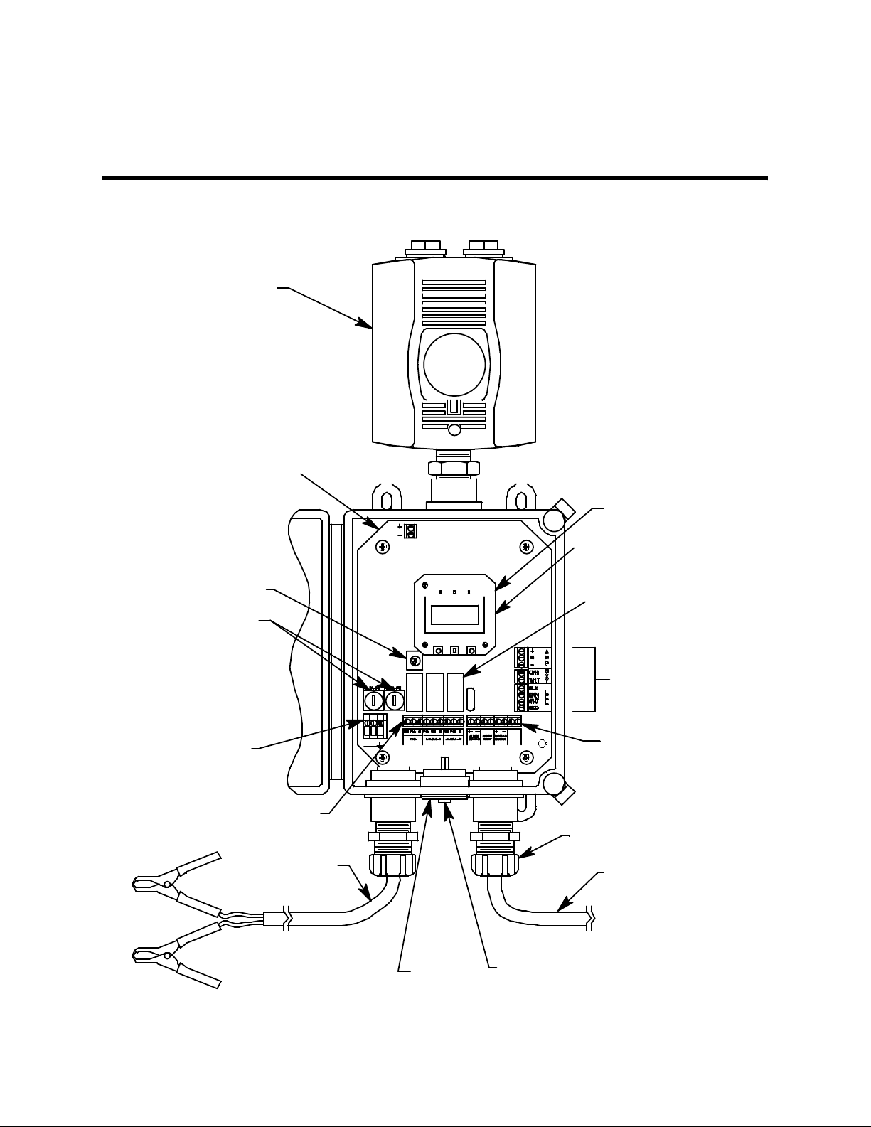
This chapter describes external and internal components of the Beacon 110 Rig Monitor.
HORN/STROBE
MAINPCB
POWER SWITCH
DC FUSES
DC IN
TERMINAL STRIP
ALARM TERMINALSTRIP
12VDC BATT ERY
CABLE
CONTROL PCB
POWER CONVERTER
(UNDER CONTR OL P CB)
RELAY (3X)
DETECTOR/
TRANSMITTER
TERMINAL
STRIPS
FAC TORY
12 VDC
WIRED
CONTROLLER
TERMINALSTRIP
CABLE BUSHING (2X)
DETECTOR CABLE
BUZZ ER
RESET SWITCH
(BEHIND BUZZER)
Figure 1: Beacon 110 Rig Monitor Component Location
3 Beacon 110 Rig Monitor Operator’s Manual
Page 9

External Description
This section describes th e hous ing and all external componen ts of the B eacon 110 Rig Monitor. For
the purposes of this description, the housing door is considered the front of the monitor.
Housing
The Rig Monitor’s fiberglass housing is weather- and corrosion-resistant. It is suitable for
installation where general purpose equipment is in use. The housing door is hinged on the left side
and is secured by two latches on the right side. The display screen and status lights are visible
through a window in the housing door. Four mounting feet are attached to the back of the housing
(one at each corner). The mounting feet allow installation to a ve rtical sur face. Two cable bushings
on the bottom of the housing are for wiring connections. One cable bushing is for the 12 VDC
battery connection. The other is for the direct connect H
wired.
Buzzer
The buzzer is on the bottom center of t he housing in front of the reset switch. The buzzer sounds
audible alarms to warn you of gas alarms and instrument failures.
Reset Switch
S detector connection. Both are factory
2
The reset switch is on the bottom of the housing behind the buzzer. The reset switch serves four
functions:
• You can reset the alarm circuits for “latched” alarms after an alarm 1 or alarm 2 condition
passes.
• You can silence the buzzer during an alarm 1 or an alarm 2 condition. You cannot silence a fail
condition.
• You can turn off the strobe/horn in an alarm 1 condition once the condition has passed.
• You can display and reset the minimum and maximum readings that the Rig Monitor has
experienced since the last min/max reset or startup.
Alarm Strobe/Horn
The Rig Monitor has a red alarm strobe light/horn installed on the top of the housing. The Rig
Monitor retains its NEMA 4X rating with the strobe installed. Strobe/horn operation is controlled
by the Alarm 1 relay contacts. The relay action settings can be changed in Configuration Mode.
Beacon 110 Rig Monitor Operator’s Manual 4
Page 10
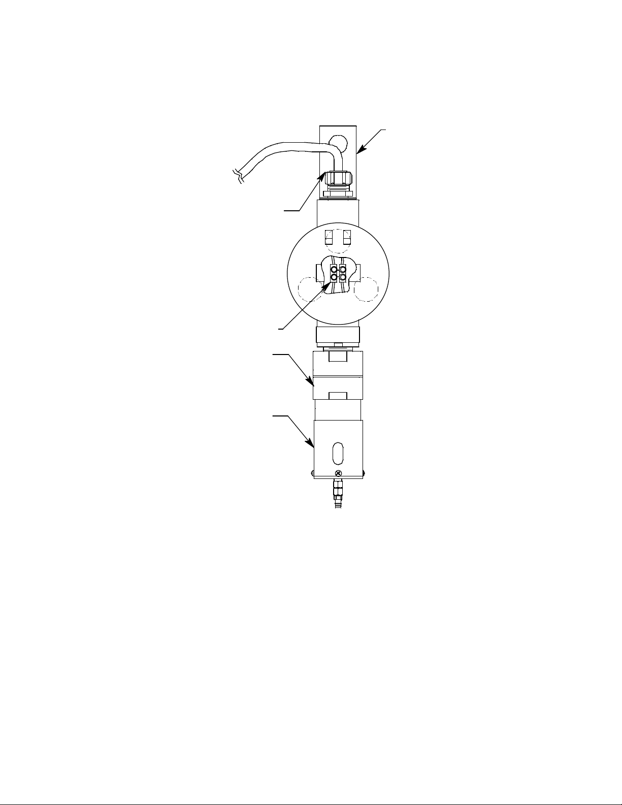
H2S Detector and Cable
The H2S detector consists of a junction box with a mounting bracket, the detector, and the
calibration cup/splash guard.
Mounting Bracket
To Beacon 110
Cable Bushing
Terminal Strip
H2S Detector
(Factory Wi red)
CalibrationCup/
Splash Guard
Figure 2: H
S Detector Component Location
2
The H2S detector is factory wired through the right cable bushing of the Beacon 110 controller an d
has a 25 foot cable for remote installation. The mounting bracket at the top of the junction box is
used to mount the junction box. The junction box protects the detector wiring connections. Three
spacers installed on the back of the junction box control the distance of the junction box from a
mounting surface and ensure that there is enough room to perform a calibration. A cover on the
front of the junction box allows access to the interior of the junction box.
The detector housing body protects the sensing componen ts w ith i n th e h ous i ng. U s e the removable
cap near the bottom of the housing to access the sensor for maintenance or replacement. The cap
protects the sensor from damage and includes a flame arrestor which contains any sparks which
may occur within the detector housing. A cap gasket seals the interface between the housing and
cap. A flame arrestor guard is permanently bonded to the cap.
The calibration cup/splash guard is screwed onto the bottom of the flame arrestor guard.
5 Beacon 110 Rig Monitor Operator’s Manual
Page 11
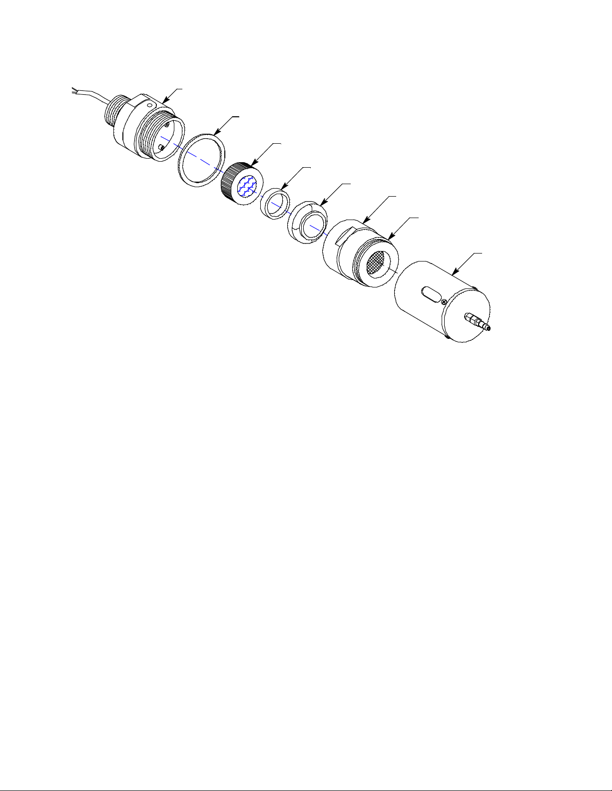
Detector Housing Body
/
Cap Gasket
H2S Pl ug - in Senso r
Spacer
Rubber Boot
Detector
Housing Cap
Flame
Arrestor
Guard
Calibration Cup
Splash Guard
Figure 3: H2S Detector Component Location
The sensor is secured within the sensor housing by four pins. Through a series of chemical and
electrical reactions, the sensor produces an electrical outp ut that corres po nds t o the det ecti on rang e
of the detector . A pre-amplifier, located between the sockets and two interconnect wires, conditions
the sensor’s signal before the signal reaches the controller. A rubber boot and spacer are installed
on the sensor face to ensure that the sensor remains plugged into the detector housing body.
12 VDC Battery Cable
A 50 foot cable with clamps for connection to a 12 VDC battery (customer supplied battery not
included) is factory-wired through the left ca ble bush ing of the Beacon 110. One end of the cable is
connected to the Beacon 110 terminal strips.
Beacon 110 Rig Monitor Operator’s Manual 6
Page 12
Internal Description
This section describes the internal components of the Beacon 110 Rig Monitor
Power Converter
The power converter is located underneath the control PCB. It takes 12 VDC voltage supplied to
the Rig Monitor and converts it to 24 VDC which is used to run the Rig Monitor.
Main Printed Circuit Board (PCB)
The main PCB is mounted inside the housing. The main PCB includes the terminal strip s, relays ,
fuses, and power switch.
Terminal Strips
The Rig Monitor includes terminal strips for field and factory wiring connections. See “Wiring the
Beacon 110 Rig Monitor” on page 13 for detailed wiring procedures.
• 12 VDC In Terminal Strip. The 12 VDC In terminal strip is a 3-point terminal strip located in
the lower left corner of the main PCB. It facilitates wiring from a 12 VDC battery with the
factory supplied battery cable. Table 2 lists the function of each terminal.
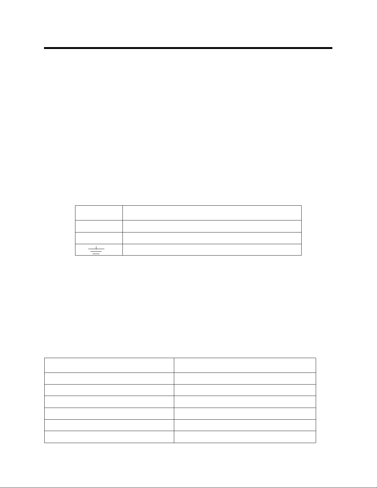
Table 2: Terminal Assignments for the DC In Terminal Strip
Terminal Connects to:
12 VDC + Positive (white) wire from 12 V battery.
12 VDC - Negative (black) wire from 12 V battery.
Earth ground, factory wired
• Alarm Terminal Strip. The 9-point alarm terminal strip is located along the bottom edge of
the main circuit board to the right of the DC In terminal strip (see Figure ). It facilitates wiring
external alarm devices (horn, strobe, etc.) to the alarm relay contacts and includes common
(C), normally closed (NC) and normally open (NO) terminals for fail, alarm 1, and alarm 2.
The factory installed s trobe/ horn i s factor y wired to the NO contact o f th e Alarm 1 relay and to
the (-) contact of the external DC terminal.
• Controller Terminal Strip. The 8-point controller terminal strip is located along the bottom
edge of the main circuit board to the right of the alarm terminal strip (see Figure ). The
controller terminal strip facilitates various internal and external wiring connections. Table 3
lists the function of each terminal.
Table 3: Terminal Assignments for the Controller Terminal Strip
Terminal Connects to:
Alarm Buzzer + & - Factory installed buzzer (factory-wired)
Alarm Reset (2) Reset switch (factory-wired)
4 - 20 mA Output + + connection of 4 - 20 mA output
4 - 20 mA Output - - connection of 4 - 20 mA output
FACTORY WIRED (TB9) (right terminal) not used
FACTORY WIRED (TB9) (left terminal) - connection from 12 VDC strobe, factory wired
7 Beacon 110 Rig Monitor Operator’s Manual
Page 13

• Detector/Transmitter Terminal Strips. Three adjacent terminal strips are located along the
right side of the main circuit board above the controller terminal strip (see Figure ). These three
terminal strips labelled LEL, Oxy , and AMP facilitate wiring connections to a detector or a 4 -
20 mA transmitter. The Beacon 110 Rig Monitor only uses the top terminal strip, labelled
AMP, for wiring to the H
S detector. The LEL and Oxy terminal strips are not used.
2
Ground Stud
The threaded ground stud is used for making connections to earth ground. It is connected through
the main PCB to the (earth) terminal on the 12 VDC In terminal strip. A kep nut on the stud
may be removed for installation of one or more lugs to make wiring connections. The detector
cable shield’s drain wire is connected to the stud.
Relays
The Rig Monitor includes three alarm relays located above the alarm terminal strip. They are from
left to right Fail, Alarm 1, and Alarm 2. The relays are form C, single-pole, double-throw (SPDT)
and rated for 10 amps at 250 VAC (resistive). The Rig Monitor uses the Alarm 1 relay to control the
factory installed strobe/horn. Only the Fail and Alarm 2 relays are available for customer use.
NOTE: You can select normally energized (N.EN) or normally de-energized (N.DE-EN)
settings for the alarm 1 and alarm 2 relays. S ee “Chapter 5: Configuration Mode” on
page 22.
The fail relay is factory set as normally energized and is not user adjustable.
DC Circuit Protection
Two DC fuses are used in the Rig Monitor. The two fuses are located on the left side of the main
PCB, above the 12 VDC power terminal strip. They cut off the incoming 12 VDC power in the
event of a short circuit or other electrical fault which causes a high curren t draw in the Rig Monitor.
They are housed in vertical fuse holders and are he ld in the holder by a qu arter turn cover. They are
labelled as F1 (left fuse) and F2 (right fuse) on the PCB silk-screen and are rated at 3 A, 250 V.
Power Switch
The power switch is located to the right o f the power s upply and above the relays ( see Figure ). The
power switch turns the incoming 12 VDC power source on and off at the Rig Monitor. When the
switch is up, the power switch is on.
Control PCB
The LCD display and control buttons are located on th e control PCB. It is installed on the main
PCB with three standoffs. The control PCB is connected to the main PCB with the display cable
which is a ribbon cable terminated with 20 position rectangular connectors on each end. The
display cable connects to the control PCB on the back of the top edge and to the main PCB directly
below the control PCB.
Beacon 110 Rig Monitor Operator’s Manual 8
Page 14

F
Alarm 1 LED
er
ail LED
F
A1 A2
Alarm 2 LED
LCD Display
Contrast
Potentiomet
UP/YES DOWN/NO
ENTER
Control Switches
Figure 4: Control PCB Component Location
LCD Display
The LCD display is located at the top of the control PCB. It indicates the current gas reading and
displays messages and parameters in the Rig Monitor’s operating modes.
Contrast Potentiometer
The contrast potentiometer is located to the right of the LCD display. It is used to adjust the contrast
of the LCD. If the background of the LCD appears so dark that the characters are not visible or if
the characters are too dim, turn the adjustment screw on the potentiometer clockwise or
counterclockwise until the desired visibility is obtained.
Control Buttons
The Rig Monitor includes three push button switches that allow you to enter the Rig Monitor’s
operating modes, navigate through the modes, update settings, and save changes to the settin gs .
The push button switches are located along the bo ttom ed ge o f th e con trol PCB (s ee Figu re 4). The
UP/YES button is on the left, the DOWN/NO button is in the middle, and the ENTER button is on
the right.
Table 4: Beacon 110 Rig Monitor Control Button Functions
Switch Function
UP/YES • Saves settings
DOWN/NO • Cancels setting changes
9 Beacon 110 Rig Monitor Operator’s Manual
• Changes the displayed setting
• Enters Calibration Mode
• Enters Configuration Mode (press with ENTER button)
• Changes the displayed setting
• Displays the Information Screen
Page 15

Table 4: Beacon 110 Rig Monitor Control Button Functions
Switch Function
ENTER • Initiates operations
• Enters Configuration Mode (press with UP/YES button)
• Accepts displayed parameters
Status LEDs
The Rig Monitor includes three active status LEDs that are located above the display (see Figure).
Two LEDs, labelled RX and TX, to the right of those described below, are not active.
• Fail LED
The fail LED turns on when the Rig Monitor is experiencing a fail condition. A fail
condition can be caused by a detector failure or low detector signal.
• Alarm 1 LED
The alarm 1 LED is on when the Rig Monitor is experiencing an alarm 1 condition.
• Alarm 2 LED
The alarm 2 LED is on when the Rig Monitor is experiencing an alarm 2 condition.
Beacon 110 Rig Monitor Operator’s Manual 10
Page 16

Chapter 3: Installation & Startup
Overview
This chapter describes procedures to mount the Beacon 110 Rig Monitor, make wiring connectio ns
to the monitor, and start up the monitor.
WAR NING: Perform all installation and start-up procedures in a “fresh air” environment
(environment known to be free of toxic gas, and of normal oxygen content). The
Beacon 110 Rig Monitor is not in operation as a gas monitoring system until the
start-up procedure is complete.
Mounting the Beacon 110 Rig Monitor
Perform the following procedure to install the instrument housing at the mounting site.
7.20
5.6
4.83
4.00 MT G
4.50"
8.0" Max
Ø .30 X .50SLOTS ( 4X) MOUNTING
1.70
ALM 1FAIL
ALM 2
8.50
10.00
Conduit
Hubs (3X)
1.47
3/4
BEACON 110
GAS MON I TOR
RESET
3.03
Door Latches
8.94 MT G
3/4 Cable
Bushings
(2X)
Figure 5: Beacon 110 Rig Monitor Outline & Mounting Dimensions
11 Beacon 110 Rig Monitor Operator’s Manual
Page 17

1. Select the mounting site. When you select the mounting site consider the following factors:
5
• Is a DC power source available?
• Is there enough room to open the housing door and make wiring connections through the
cable bushings at the bottom of the housing?
• Are the display screen and status lights on the Rig Monitor visible?
2. If necessary, close and latch the Rig Monitor housing door.
3. Position the monitor on a vertical surface at eye level (4 1/2 to 5 feet from the floor).
4. Insert 1/4 in. or 5/16 in. screws through the slots in the Rig Monitor mounting feet at each
corner of the housing to secure the housing to the mounting surface.
5. Use the mount ing bracket to hang the H
S detector at approximately breathing level.
2
To Left
Cable
Bushing
To Right
Cable
Bushing
12 VDC
Batter y
Cable
Detector
Cable
Mounting
Bracket
1.50
Ø .7
.75
14.2" Max
Figure 6: Junction Box Outline & Mounting Dimensions
6. At the monitoring site you select, hang the junction box with the detector facing down (see
Figure 6).
Beacon 110 Rig Monitor Operator’s Manual 12
Page 18

Wiring the Beacon 110 Rig Monitor
This section describes procedures to connect external alarm(s) and a recorder to the Rig Monitor.
The power, detector, and strobe/horn wiring are all factory wired as shown below.
Strobe / Horn
Beacon 110
Mai n PCB
L
N
G
24V
TB1
OUT
GND
Power
IN
Converter
Red
Black
Detector
Cable
PCB
Ground
Conduit Hubs
ALARM
ALARM
ALARM
4-2 0mA
RESET
RESET
BU ZZE R
FAIL
ALA RM 1
ALAR M 2
OUTPUT
FACTOR Y
WIRED
Terminal Block
Buzzer
Reset
Switch
Black
Red
BlackWhite
Black
White
Battery
Black
Red
TO 12
VDC
Battery
Terminals
H2S De te cto r
Cable
Figure 7: Rig Monitor Factory Wiring
13 Beacon 110 Rig Monitor Operator’s Manual
Page 19

WARNING: Make all connections to the Beacon 110 Rig Monitor before you plug in or turn
ALARM-2
ALARM-1
FAIL
Exte rn al Al ar m Dev ic e
on the DC power source. Before you make any wiring adjustments, always verify
that all power sources are not live.
Connecting DC Power
Perform the following functions to connect the Rig Monitor to DC power. One end of the battery
cable is already factory wired to the appropriate terminals at the Rig Monitor housin g. Use the ot her
end to connect a 12 VDC battery.
NOTE: Be sure to turn off the Beacon 110 Rig Monitor before connecting or disconnecting it
from the 12 VDC battery.
1. Turn off, unplug, or disconnect all incoming power to the Rig Monitor.
2. Open the housing door, then place the power switch in the OFF position.
3. Connect the red battery clamp to the (+) terminal of the 12 VDC battery.
4. Connect the black battery clamp to the (-) terminal of the 12 VDC battery.
Connecting External Alarms
Perform the following procedure to connect external alarms to the Rig Monitor’s Fail or Alarm 2
terminals. The Alarm 1 terminals are factory wired and are not available for field use.
1. Disconnect the bat tery clamps from the + and - terminals of the 12 VDC battery.
2. Open the housing door, then place the power switch in the OFF position.
3. Locate the alarm terminal strip. See Figure 1 to assist you in locating the alarm terminal strip.
4. Install an appropriately rated cable bushing i n the Rig Monitor housing. Both factory supplied
conduit hubs are used in the Rig Monitor, so you will need to drill a hole in the housing for a
conduit hub and cable bushing.
5. Guide the wiring of the external alarm through the new cable bushing.
6. Connect the leads from the external alarm to the appropriate terminals on the alarm terminal
strip as shown in Figure 8 to obtain the desired operation.
Beacon 110 Alarm
NCNO
CNO
Factory
Wired
NC C NCNO C
Terminal Strip
(+) H
(-) N
External
Source
Power
Beacon 110 Rig Monitor Operator’s Manual 14
Figure 8: Typical Alarm Device Wiring
7. Repeat steps 5 and 6 for an additional alarm device.
Page 20

Connecting Recorders
A
T
Perform the following procedure to connect an analog signal recording device to the Rig Monitor.
The output at the recorder output terminals is a 4 - 20 mA signal that is proportional to the detection
range of the H
Alarm 1 terminals are factory wired and no t available for field use.
1. Disconnect the battery clamps from the + and - terminals of the 12 VDC battery.
2. Open the housing door, and locate the recorder output terminals on the controller terminal
strip. See Figure 1 to assist you in locating the recorder output terminals. They are labelled 4 -
20 mA OUTPUT + and 4 - 20 mA OUTPUT -.
3. Place the power switch in the off position.
4. Install an appropriately rated cable bushing i n the Rig Monitor housing. Both factory supplied
conduit hubs are used in the Rig Monitor, so you will need to drill a hole in the housing for a
conduit hub and cable bushing.
5. Guide the wiring from the recording device through the new cable bushing.
6. Connect the leads from the recording device to the analog output terminal strip as shown in
Figure 9 below.
S detector head connected to the Rig Monitor’s Fail or Alarm 2 terminals. The
2
4-20 m
OUTPU
Recording Device,
500 Ohms Max
Impedance
Figure 9: Recorder Output Wiring
15 Beacon 110 Rig Monitor Operator’s Manual
Page 21

Start Up
Introducing Incoming Power
Perform the following procedure to place the Rig Monitor into normal operation.
1. Complete the mounting and wiring procedures described earlier in this chapter.
2. Verify that all wiring connections are correct and s ecure and that the Rig Monitor’s power
switch is in the OFF position.
3. If not already connected, connect the battery clamps to the + and - terminals of the 12 VDC
battery.
4. Turn on the power switch.
5. The LCD display will indicate the firmware version when the Rig Monitor is first powered up
and will then count down a one minute warm-up period before normal operation begins.
During normal operation, the display will indicate the current gas reading and target gas.
Verify that the display is indicating the current gas reading and target gas after the warm-up
period is complete and normal operation begins, for example:
H2S
0 ppm
NOTE: To prevent unwanted alarms during warm up, the alarm circuits are not active during
the warm-up period.
6. The H
S detector will begin operating once power is introduced to the Rig Monitor.
2
Beacon 110 Rig Monitor Operator’s Manual 16
Page 22

Chapter 4: Operation
Overview
This chapter describes the Beacon 110 Rig Monitor in normal operation. This chapter also
describes the Rig Monitor in alarm 1, alarm 2, and fail conditions and suggests response to these
conditions.
Normal Operation
Normal operation is defined as follows:
• The start-up procedure is complete.
• The Rig Monitor is not indicating an alarm 1, alarm 2, or fail condition.
• The Rig Monitor is not in Calibration or Configuration Mode.
During normal operation, the Rig Monitor simultaneously displays the current gas reading, unit of
measure, and target gas.
Information Screen
The Information Screen displays the Rig Monitor’s operating voltage and firmware and hardware
information. To display the Information Screen, do the following:
1. Press and hold the DOWN/NO button for 3 seconds. The Information Screen will appear.
2. Continue holding the DOWN/NO button to keep the Information Screen on the display. The
top line indicates the operating voltage that the power converter is providing to the Rig
Monitor. The second line indicates the firmware that is running, version 5.0 in this example,
and the Rig Monitor’s hard ware vers i on , vers ion 2A in this example. This information may be
useful if you need to contact the facto ry with questions about the Rig Monitor.
3. Release the DOWN/NO button when you are done viewing the Information Screen. The
display will return to the normal operation screen within a couple of seconds.
NOTE: The Information Screen is not a good indicator of battery life because the power
converter will operate as normal and have an output of 24 volts until the 12 VDC
battery dies.
H2S
0 ppm
24.2V
v5.0 2A
17 Beacon 110 Rig Monitor Operator’s Manual
Page 23

4 - 20 mA Signal Output Operation
The output at the 4 - 20 mA output terminals is a 4 - 20 mA signal that is proportional to the
detection range of the Rig Monitor. During normal operation, this signal tracks the gas
concentration on the LCD.
There are several circumstances where the signal output will not track the display reading but will
behave as follows:
• When the Rig Monitor is in its warm-up period, the signal output will be fixed at 4 mA (zero).
• If you e nter Calibration Mode or Configuration Mode, the signal output will be fixed at 3.5 mA
until the Rig Monitor returns to normal operation.
• If the Rig Monitor’s input power decreases below 10 volts so that the Rig Monitor is in a low
power alarm, the signal output is fixed below 2.4 mA until the low power alarm is cleared.
NOTE: Under typical operating conditions, there will be no low power alarm. The 12 VDC
battery that is recommended for operation will die before the power converter
recognizes a low power condition.
• If the R ig Monitor goes into a fail condition, after a 30 second delay, the signal output is fixed
below 2.4 mA until the fail alarm is cleared. During the 30 second delay, the output follows the
detector output. In the case of a downscale reading, the displayed gas reading will only go as
low as -10% of full scale but the signal output will continue to track the reading even if it’s
lower than -10% of full scale.
Viewing and Resetting Min/Max
Readings
The reset switch may be used to view and reset the minimum and maximum gas readings.
NOTE: Minimum and maximum readings are reset if the instrument is turned off.
1. While the Rig Monitor is in normal operation, press and hold the reset switch button for 5
seconds.
2. The display will indicate the minimum reading on the bottom display line and the maximum
reading on the top display line for about 3 seconds before indicating <RESET> TO CLEAR.
3. To return to normal operation without resetting the minimum and maximum readi ngs, do not
press the reset switch button and allow the unit to return to normal operation. It will return to
normal operation in about 5 seconds.
To reset the min imu m and max imu m r eadi n gs, p r ess and hol d the r es et s wit ch butt on
while the <RESET> TO CLEAR message is on the display until the dis p lay indicates
Min/MAX Is RESET. Release the reset switch button.The unit will then return to
normal operation in about 5 seconds.
Beacon 110 Rig Monitor Operator’s Manual 18
Page 24

Alarm Indications
NOTE: The Beacon 110 Rig Monitor includes alarm on and alarm of f delay settings for alarm 1
and alarm 2. The alarm indications described in this section operate according to the
factory set alarm settings. See Table 6 on page 23 for all the factory settings.
Table 5: Visual and Audible Alarm Indications
Condition Cause Visual Indication(s)
Alarm 1
1
Increasing gas reading at or above the
alarm 1 setpoint
• Alarm 1 LED is on
• Gas reading alternates with
ALARM-1 message
Audible
Indication
• Pulsing tone
• Strobe/horn
turns on
• Strobe/horn turns on
Alarm 2
1
Increasing gas reading at or above the
alarm 2 setpoint
• Alarm 2 LED is on
• Gas reading alternates with
• Pulsing tone
ALARM-2 message
Fail • Disconnected or misconnected
detector head wiring
• Display reading at -10% of full scale
or lower
• Defective components
• Fail LED is on
• FAIL mes sage replaces gas
reading
NOTE: There is a 30 second
delay on the fail indications.
Low Power Dead 12 VDC battery • Fail LED is on
• Steady tone
• None
• LowPower message
NOTE: Under typical operating conditions, there will be no low power alarm. The 12 VDC battery that is recommended for operation will die before the power converter recognizes a low power condition.
1
*
If the Beacon 110 Rig Monitor is in both an alarm 1 and an alarm 2 condition, both alarm LEDs are on
and the display alternates between the gas reading and the ALMS 1&2 message.
NOTE: You can select normally energized (N. EN) or normally de-energized (N. DE-EN)
alarm 1 and alarm 2 relay action settings in Configuration Mode. The following
sections describe the standard factory setting for these relays which is N. DE-EN.
The fail relay is set as normally energized in the firmware and is not user-adjustable.
CAUTION: Changing the relay action setting for the Alarm 1 relay in Configuration Mode will
cause the strobe/horn to be on during normal operation.
19 Beacon 110 Rig Monitor Operator’s Manual
Page 25

Alarm 1 Condition
Alarm 1 Condition Indications
When the gas reading reaches the alarm 1 setpoint, the Rig Monitor senses an alarm 1 condition.
The Rig Monitor alerts you to an alarm 1 condition as foll ows:
• The alarm 1 LED turns on.
• The gas reading alternates with the ALARM-1 message.
• The buzzer sounds a pulsing tone.
• The alarm 1 relay energizes and the strobe/horn activates.
Responding to an Alarm 1 Condition
1. Follow your establ ished procedure for a toxic gas condition.
2. The alarms are factory set as latching. After the gas reading falls below the alarm 1 setpoint,
press the reset switch to reset the alarm 1 circuit. Resetting the alarm 1 circuit silences the
buzzer, turns off the alarm 1 LED, returns the LCD to the normal operation screen, deenergizes the alarm 1 relay, and turns off the strobe/horn.
NOTE: If the reset switch is pressed while the Beacon 110 Rig Monitor is in an alarm 1
condition, the buzzer will be silenced and the alarm 1 LED will flash.
You cannot de-energize the alarm 1 relay and consequently turn off the strobe/horn
until the gas reading falls below the alarm 1 setpoint.
Alarm 2 Condition
Alarm 2 Condition Indications
When the gas reading reaches the alarm 2 setpoint, the Rig Monitor senses an alarm 2 condition.
The Rig Monitor alerts you to an alarm 2 condition as foll ows:
• The alarm 2 LED turns on.
• The gas reading alternates with the ALARM-2 message.
• The buzzer sounds a pulsing tone.
• The alarm 2 relay energizes and the strobe/horn will remain activated.
NOTE: If the Beacon 110 Rig Monitor is in both an alarm 1 and alarm 2 condition, both the
alarm 1 and alarm 2 LEDs will be on, the gas reading will alternate with the ALMS
1&2 message, and both alarm relays will energize.
Beacon 110 Rig Monitor Operator’s Manual 20
Page 26

Responding to an Alarm 2 Condition
1. Follow your establ ished procedure for a toxic gas condition.
2. The alarms are factory set as latching. After the gas reading falls below the alarm 2 setpoint,
press the reset switch to reset the alarm circuit. Resetting the alarm circuit silences the buzzer,
turns off the Alarm 2 LED, returns the LCD to the normal operation screen, and de-energizes
the alarm 2 relay.
NOTE: If the reset switch is pressed while the Rig Monitor is in an alarm 2 condition, the
buzzer will be silenced and the alarm 2 LED will flash but all other indications will
remain unchanged.
You cannot de-energize the alarm 2 relay until the gas reading falls below the alarm 2
setpoint.
Fail Condition
Fail Condition Indications
The Rig Monitor indicates a fail condition for any of the following:
• The detector head wiring is disconnected or incorrectly connected.
• The display reading is -10% of full scale or lower.
When the Rig Monitor senses a fail condition, it alerts you as follow s:
• The fail LED turns on.
• The gas reading is replaced by the FAIL message.
• The buzzer sounds a steady tone.
• The fail relay de-energizes.
NOTE: The fail alarm has a 30 second delay.
Responding to a Fail Condition
NOTE: A fail condition cannot be reset using the reset switch.
1. Verify that the detector head wiring is correctly and securely connected.
2. Verify that the replaceable plug-in sensor is properly installed.
3. If necessary set the zero reading for you r detect or head as describ ed in “Calibration Mode” on
page 25.
Low Power Condition
The 12 VDC battery that is recommended for operation of the Rig Monitor is typically dead before
the power converter recognizes a low power condition. As a result, when the Rig Monitor is used
with a 12 VDC battery, there may be no low power alarm and the unit will instead shut off once the
battery is dead.
21 Beacon 110 Rig Monitor Operator’s Manual
Page 27

Chapter 5: Configuration Mode
Overview
This chapter describes how to view and change Beacon 110 Rig Monitor parameters using
Configuration Mode. It is accessed using the program buttons.
Configuration Mode incl udes a 5-mi nute time-o ut featur e. If you do not press a cont rol but ton for 5
minutes, the Rig Monitor automatically returns to normal operation.
NOTE: If the Beacon 110 R ig Monitor returns to normal operation because of a time-out, it
enters a warm-up period just as it does when it is first turned on.
If you are installing a new Rig Monitor, it has been set up at the factory. Use
Configuration Mode only if you want to change the Rig Monitor’s setup.
Viewing & Changing Beacon 110 Rig
Monitor Parameters
1. Whil e in nor mal operation, simult aneously pr ess and h old the UP /YES and ENTER button s for
5 seconds to enter Configuration Mode. Release the buttons when the following screen
appears.
Enter
Config?
2. If you want to exit Configuration Mode, press and release the DOW N/NO button and the Rig
Monitor will return to normal operation.
If you want to continue in Configuration Mode, press and release the UP/YES button. The
target gas and the full scale will be displayed for a few seconds before the first adjustable
parameter, the alarm 1 setpoint, is displayed.
3. If you want to change the currently displayed parameter, use the UP/YES and DOWN/NO
buttons to adjust it to the desired setting, then press ENTER to continue to the next parameter.
If the currently displayed parameter is OK, press the ENTER button to proceed to the next
parameter.
Table 6 lists the Rig Monitor parameters you can set. Table 6 also lists the factory set
value for each parameter.
Beacon 110 Rig Monitor Operator’s Manual 22
Page 28

Table 6: Configuration Parameters
Parameter
(Factory Set Value)
ALARM-1
(10 ppm)
ALARM-1 (activation)
(Increase)
ALARM-1 (relay action)
(N. DE-EN)
ALARM-1 (relay reset)
(LATCH)
A1Stro be The strobe controlled by thi s para meter is not inst alled in the Rig Monitor.
A1 OnDy (alarm 1 on delay)
(1 secs)
The gas reading at which the Rig Monitor initiates an alarm 1 condition.
Indicates if the alarm 1 circuit is activated by gas readings increasing
Increase) or decreasing (Decrease) to the ALARM-1 Level.
(
• Note: Changing this parameter will affect the operation of the factory
installed strobe/horn. Do not change this parameter from the factory
setting.
If set as N. DE-EN, th e alarm 1 relay is de-ene rgized in norm al opera tion
and energizes w h en an alarm 1 condition is initiated.
If set as
de-energizes when an alarm 1 cond iti on is initia ted .
• Note: Changing this parameter will affect the operation of the factory
If set as LATCH, you must press the reset switch to reset the alarm 1 cir-
cuit after the alarm 1 condition passes.
If set as
cuit after the alarm 1 condition passes.
The amount of time the Rig Monitor delays activation of the alarm 1 circuit once an alarm 1 condition is ini tia ted .
N. EN, the alarm 1 relay i s energized in normal operation and
installed strobe/horn. Do not change this parameter from the factory
setting.
SELF-RST, the Rig Monitor autom a tically resets the alarm 1 cir-
Description
A1 OffDy (alarm 1 off delay)
(0 sec.)
ALARM-2
(50 ppm)
ALARM-2 (activation)
(Increase)
ALARM-2 (relay action)
(N. DE-EN)
ALARM-2 (relay reset)
(LATCH)
A2Stro be The strobe controlled by thi s para meter is not inst alled in the Rig Monitor.
A2 OnDy (alarm 2 on delay)
(1 secs)
A2 OffDy (alarm 2 off delay)
(0 sec.)
The amount of time the Rig Monitor delays turning off the alarm 1 circuit
once an alarm 1 condition passes. This parameter appears only if the
alarm 1 relay res e t setting is set to
The gas reading at which the Rig Monitor initiates an alarm 2 condition.
Indicates if the alarm 2 circuit is activated by gas readings increasing
Increase) or decreasing (Decrease) to the ALARM-1 Level.
(
If set as
and energizes w h en an alarm 2 condition is initiated.
If set as
de-energizes when an alarm 2 cond iti on is initia ted .
If set as
circuit after the alarm 2 condition passes.
If set as
cuit after the alarm 2 condition passes.
The amount of time the Rig Monitor delays activation of the alarm 2 circuit once an alarm 2 condition is ini tia ted .
The amount of time the Rig Monitor delays turning off the alarm 2 circuit
once an alarm 2 condition passes. This parameter appears only if the
alarm 2 relay res e t setting is set to
N. DE-EN, the alarm 2 relay is de-energized in normal opera tion
N. EN, the alarm 2 relay i s energized in normal operation and
LATCH, you must press the ENTER button to reset the alarm 2
SELF-RST, the Rig Monitor autom a tically resets the alarm 2 cir-
SELF--RST.
SELF-RST.
23 Beacon 110 Rig Monitor Operator’s Manual
Page 29

Table 6: Configuration Parameters (Continued)
ZeroSupp
(2 ppm)
FILTER
(5 secs)
CAL Time
(15 mins)
Parameter
(Factory Set Value)
4. When you have scrolled through all the adjustable parameters, SAVE IT? YES/NO appears on
the display.
5. To save the adjustments made, press and release the UP/YES button. Config Saved is
indicated on the display for a few seconds and th e Rig Monitor returns to normal operation.
Description
The zero suppression feature helps prevent “jumpy” readings near the
fresh air reading.
For example, if the zero suppression setting for the H
ppm, the Rig Monitor will display a reading of 0 ppm for gas readings
from -2 ppm to 2 ppm.
The filter feature helps “smooth out” jumpy or noisy signals from the
detector. You can set the filter from 0 seconds to 60 seconds in 5 seconds increments.
The displayed gas reading is the average reading over the previous time
period defined by the filter setting. So if the filter is set to 5 seconds, the
displayed gas reading is the average over the past 5 seconds.
The calibration tim e-out set s the am ount of time after th e last bu tton push
while in Calib ration Mode th at the Ri g Monitor wil l wait before returning to
normal operation. If the calibration time-out is set to
Rig Monitor will return t o norma l operation automa tical ly 15 minu tes af ter
the last button pu sh.
S detector is 2
2
15 mins, then the
If you do not wish to save the adjustments, press and release the DOWN/NO button. The DO
OVER? YES/NO message will display. Press and release the DOWN/NO button. The
ABORT? YES/NO message will display. Press the UP/YES button to return to normal
operation.
Beacon 110 Rig Monitor Operator’s Manual 24
Page 30

Chapter 6: Maintenance
Overview
This chapter describes how to calibrate the Beacon 110 Rig Monitor using Calibration Mode,
replace the DC fuses, and preventive maintenance procedures for the Rig Monitor. It includes a
troubleshooting guide for problems you may encounter with the Rig Monitor.
Calibration Frequency
Although there is no particular calibration frequency that is correct for all applications, a calibration
frequency of every 3 to 6 months is adequate for most Rig Monitor applications. Unless experience
in a particular application dictates otherwise, RKI Instruments, Inc. recommends a calibration
frequency of every 3 months.
If an application is not very demanding, for example detection in a clean, temperature controlled
environment where hydrogen sulfide is not normally present, and calibration adjustments are
minimal at calibration, then a calibration frequency of every 6 months may be adequate.
If an application is very demanding, for example if hydrogen sulfide is present often and in
significant concentrations or the environment is not well controlled, then more frequent calibration
than every 3 months may be necessary.
Calibration Mode
Calibration Mode is used to calibrate the Rig Monitor’s detector head. All calibration adjustments
are made at the Rig Monitor housing after calibration gas is applied to the detector.
Calibration Gas Response Memory Feature
The Rig Monitor has the capability to “remember” the detector’s response to the calibration gas
after the gas is remove d from the detector during the fresh air or span adjustment procedure. This
feature enables one person to perform calibration if the detector is mounted remotely from the Rig
Monitor. When zero air is applied to the Rig Monitor during a fresh air adjustment, the Rig Monitor
will freeze the display reading at the lowest response and the Rig Monitor will continue to display
this reading and retain it in its memory until the fresh air adjustment procedure is completed. When
calibration gas is applied to the Rig Monitor during a span adjustment, the Rig Monitor will freeze
the display reading at the highest response to the calibration gas. The calibration gas can then be
removed and the Rig Monitor will continue to display this reading and retain it in its memory until
the span adjustment procedure is completed.
25 Beacon 110 Rig Monitor Operator’s Manual
Page 31

Calibration Program Flow
Figure 10 below illustrates the general flow of the Calibration Program fo r a direct connect
detector. See the next section, “Preparing for Calibration”, for instructions to enter Calibration
Mode. In general, if a question mark, “?”, is part of the display text, use the UP/YES or DOWN/NO
button to respond. Use the UP/YES and DOWN/NO buttons to increase or decrease a displayed gas
reading when performing a span (zero for oxygen) operation, and use the ENTER button to accept
a displayed value and continue.
No
Normal Op eration
Press
UP/YES
Calibrate?
Yes/No
Yes
Fresh Air
Adjust?
Yes/No
Fresh Air Adjust
Apply Gas to
Detector
Adj ust Sp an
Setting
Yes
No
Sp an Y/ N ?
Yes
Press ENTER to
Accept Span
Setting
No
Figure 10: Direct Connect Detector Head
This section describes how to calibrate the H
S detector. It includes procedures to prepare for
2
calibration, set the zero reading, set the response reading, and return to normal operation. It
describes calibration using a calibration kit that includes a calibration cup/splash guard, calibration
gas, sample tubing, and a fixed flow regulator with an on/off knob. RKI Instruments, Inc.
recommends using a 0. 5 LPM (liters per minute) fixed fl ow regulator.
Prepari ng for Ca libration
WARNING: The Beacon 110 Rig Monitor is not an active gas monitoring device during the
calibration procedure. The 4-20 mA output signal will “freeze” at 3.5 mA and
all relays will remain in their non-alarm state while the Rig Monitor is in
Calibration Mode. The 4 - 20 mA output signal will not indi cate cur rent
readings and the relays will not resu me operating normally until the Rig
Monitor is in normal operatio n ag ain.
Beacon 110 Rig Monitor Operator’s Manual 26
Page 32

1. While in normal operation, press and hold the UP/YES button for 5 seconds to enter
Calibration Mode. Release the button when the following screen appears.
Calib?
YES/NO
2. If you want to exit Calibration Mode, press and release the DOWN/NO button. The Rig
Monitor will indicate Leaving CAL Mode and the Rig Monitor will return to normal
operation.
If you want to continue with calibration, press and release the UP/YES button. The display will
indicate the target gas and CAL Mode for a few seconds before showing FreshAir Adjust?.
Setting the Zero Reading
1. The display will indicate FreshAir Adjust? as described above in “Preparing for Calibration”.
2. If you want to skip adjusting the fresh air reading, press and release the DOWN/NO button.
The display will indicate SPAN w/Cal Gas?. Skip to Step 11.
If you want to continue with adjusting the fresh air reading, press and release the UP/YES
button. ENTER will alternate with FreshAir on the top display line and the current gas
reading will be on the bottom display line.
3. If the detector is in a fresh air environment, press and release the ENTER button. The Rig
Monitor will perform a fresh air adjustment and the display will indicate SPAN w/Cal Gas?.
Continue to the next section, Setting the Response Reading.
If you suspect the detector area is not a fresh air environment, continue with Step 4.
4. Screw the regulator into the zero air calibration cylinder.
5. Use the calibration ki t sampl e tubi ng to connect the fixed flow regulat o r to the calibrat ion cup/
splash guard.
6. Turn the regulator’s on/off knob counterclockwise to open it. The Rig Monitor will freeze the
display reading at the lowest level reached while applying zero air.
7. Allow the gas to flow for two minutes.
8. Turn the regulator’s on/off knob clockwise to close it. The Rig Monitor will continue to
display the minimum gas response on the display and retain the response level in its memory.
9. Press and release the ENTER button on the Rig Monitor controller. The Rig Monitor will
perform a fresh air adjustment and the display will indicate SPAN w/Cal Gas?.
10. If you applied zero air to the detector, unscrew the regulator from the zero air calibration
cylinder.
11. If you applied zero air to the detector, leave the sample tubing connected to the regulator and
the calibration cup/splash guard.
If you did not apply zero air to the detector, use the calibration kit sample tubing to
connect the fixed flow regulator to the calibration cup/splash gu ard.
NOTE: Depending on the size of your zero air cylinder, it is possible that you will have a
different regulator for the zero air cylinder and the H
S gas cylinder. If necessary to fit
2
the H2S calibration gas cylinder, change the regulator.
27 Beacon 110 Rig Monitor Operator’s Manual
Page 33

Setting the Response Reading
1. Screw the regulator into the calibr a tion gas cylinder.
2. If you want to skip adjusting the span setting, press and release the DOWN/NO button. The
display will indicate Leaving Cal Mode and the Beacon 110 Rig Monitor will return to normal
operation.
If you want to continue with adjusting the span setting, press and release the UP/YES button.
APPLY will alternate with SPAN Gas on the top display line and the current gas reading will
be on the bottom display line.
3. Turn the regulator’s on/off knob counterclockwise to open it.
When calibration gas is applied, the Rig Monitor will freeze the display gas reading at
the highest level reached while the gas was applied.
4. Allow gas to flow for 2 minutes.
5. Turn the regulator’s on/off knob clockwise to close it. The Rig Monitor will continue to
display the maximum gas response on the display and retain the resp onse level in its memory.
6. Adjust the gas reading up or down to match the calibration gas cylinder concentration by using
the UP/YES and DOWN/NO buttons, then press and release the ENTER button.
7. The Rig Monitor will perform a span operation. The display will indicate SPAN Gas PASS for
a few seconds, then indicate SPAN Gas SAVED before indicating Leaving CAL Mode for a
few seconds.
8. Unscrew the regulator from the cylinder and disconnect the sample tubing from the calibration
cup/splash guard hose barb.
NOTE: For convenience, leave regulator connected to the sample tubing.
Returning to Normal Operation
1. The display will now alternate between the normal operation screen and the message
REMOVE CAL GAS for 1 minute. If the calibration gas has not been removed from the
detector, remove it now to avoid unwanted alarms.
During this 1 minute period, the 4 - 20 mA output will remain fixed at 3.5 mA and the
relays will remain in their non-alarm state to avoid unwanted alarms while the
calibration gas clears from the detector. At the end of the 1 minute period, the
REMOVE CAL GAS message will stop appearing and the Rig Mo nitor will return to
normal operation.
2. Store the components of the calibration kit in a safe place.
Beacon 110 Rig Monitor Operator’s Manual 28
Page 34

Adjusting Strobe/Horn Volume
The horn volume on the strobe/horn can be adjusted by doing the following:
1. Open the housing door of the Rig Monitor, then place the power switch in the OFF position.
2. Disconnect the battery clamps from the + and - terminals of the 12 VDC battery.
3. Loosen the captive screw at the bottom front of the strobe/horn.
4. Grasp the top and bottom of the strobe/horn and push up and out in order to remove the cover.
Top
Base
Captive
Screw
Push Out
Push Up Here
Figure 11: Top Case Removal
5. Turn the cover over and locate the Audio Select switch at the top of the cover as shown in the
figure below.
5
6
4
3
2
1
AUDIO
SELECT
Audio Select Switch
CANDE LLA SELECT
Strobe Brightness Switch
(DO NOT ADJUST)
Figure 12: Strobe/Horn Cover
6. The Audio Select switch can be set at any number between 1 and 6. Numbers 1-3 all produce
an intermittent buzzing sound with 1 being the loudest and 3 being the quietest. Numbers 4-6
all produce a steady buzzing sound with 4 being the loudest and 6 being the quietest. The
factory setting is 2.
29 Beacon 110 Rig Monitor Operator’s Manual
Page 35

7. Turn the Audio Select switch so that the selection arrow is pointing to the desired number.
8. Place the cover over the base and push in and down in order to reinstall the cover. Make sure
that the cover is sealed to the base by the gasket.
9. Screw the captive screw at the bottom front of the strobe/horn back in.
Replacing Components of the Rig Monitor
This section describes how to replace the fu ses, the H2S sensor, and the en tire detector assem bly. In
most cases, it is not necessary to replace the entire detector assembly.
Replacing the Fuses
The Rig Monitor has two replaceable DC fuses.
NOTE: T o replace o ther co mpo nents of the B eacon 110 Rig Monitor, contact RKI Instruments,
Inc. for further information.
1. Open the housing door of the Rig Monitor, then place the power switch in the OFF position.
2. Disconnect the battery clamps from the + and - terminals of the 12 VDC battery.
3. Locate the vertical fuse holders above the 12 VDC In Terminal Strip. The DC fuses are
labelled F1 and F2 on the main PCB silkscreen.
4. Use a flat-blade screwdriver to rotate the applicable fuse holder 1/4 turn counterclockwise. The
fuse holder releases from the socket.
5. Remove the fuse holder from the socket, then remove the fuse from the fuse holder.
CAUTION: Verify that the replacement fuse is the same type and rating as the fuse you are
replacing. See the “Parts List” on page 36 for correct fuse.
6. Install the appropriate replacement fuse in the fuse holder, then place the fuse holder in the
socket.
7. Push the fuse holder into the socket, then turn the holder 1/4 turn clockwise to secure it in the
socket.
8. Connect the battery clamps to the + and - terminals of the 12 VDC battery.
9. Place the Rig Monitor’s power switch in the ON position, then verify that the Rig Monitor
completes its warm-up sequence and enters normal operation.
10. Close and secure the housing door.
Replacing the Plug-In H2S Sensor
CAUTION: The sensor contains electrolyte which is a dilute acid. Do not disassemble the sensor
when replacing it with a new one. If sensor electrolyte comes in contact with your
skin, wash affected area thoroughly with soap and water.
1. Turn off the Rig Monitor.
2. Disconnect the battery clamps from the + and - terminals of the 12 VDC battery.
3. Unscrew the calibration cup/splash guard from the detector housing cap.
4. Unscrew the detector housing cap from the detector housing body. Make sure not to lose the
Beacon 110 Rig Monitor Operator’s Manual 30
Page 36

cap gasket.
5. Unplug and remove the H
S sensor with the rubber boot and spacer attached.
2
6. Remove the rubber boot and spacer from the old sensor.
7. Install the spacer and rubber boot onto the replacement sensor’s face.
8. Carefully plug the replacement sensor into the four-socket pattern that is located in the detector
housing.
9. Make sure the cap gasket is in place and screw the detector housing cap back onto the detector
housing body.
10. Screw the calibration cup/splash guard back onto the detector housing cap.
11. Connect the battery clamps to the + and - terminals of the 12 VDC battery.
12. Turn on the Rig Monitor and place into normal operation.
CAUTION: Allow the replacement sensor to warm up for 5 minut es before you continue with the
next step.
13. Calibrate the replacement sensor as described in the Calibration s ection of this manual.
Replacing the H2S Detector
NOTE: In most cases, it is only necessary to replace the H2S sensor.
1. Turn off the Rig Monitor.
2. Disconnect the battery clamps from the + and - terminals of the 12 VDC battery.
3. Remove the junction box cover.
4. Disconnect the detector leads from the terminal block in the junction box. Note the position of
the color-coded leads as you remove them.
5. Unscrew the calibration cup/splash guard from the detector housing cap.
6. Unscrew the detector from the junction box hub.
7. Guide the detector leads of the replacement detector through the junction box hub then screw
the mounting threads of the detector into the hub.
8. Connect the detector leads to the terminal block the same way the old detector was wired. See
Figure 7 to verify the connections are correct.
9. Screw the calibration cup/splash guard onto the new detector’s housing cap.
10. Reinstall the junction box cover.
11. Connect the battery clamps to the + and - terminals of the 12 VDC battery.
12. Turn on the Rig Monitor and place into normal operation.
CAUTION: Allow the replacement detector to wa rm up for 5 minutes before you continue with
the next step.
13. Calibrate the replacement detector as described in the Calibration section of thi s manual.
31 Beacon 110 Rig Monitor Operator’s Manual
Page 37

Preventive Maintenance
This section describes a preventive maintenance s chedule to ensure the optimum performance of
the H
S detector. It includes daily, monthly, and quarterly procedures.
2
Daily
Verify a display reading of 0 P P M H2S at the controller. Investigate significant changes in the
display reading.
Monthly
This procedure describes a test to verify that the H2S detector responds properly to hydrogen
sulfide. It describes a test using a fixed flow regulator with an on/off knob. RKI Instruments, Inc.
recommends using a 0. 5 LPM (liters per minute) fixed fl ow regulator.
NOTE: Performing a response test on the H2S detector may cause alarms. Be sure to put the Rig
Monitor into its calibration program or disable external alarms before performing this
test.
Preparing for the response test
1. While in normal operation, press and hold the UP/YES button for 5 seconds and press the UP/
YES button again when asked if you would like to enter Calibration Mode.
2. Verify that the R ig Mon itor display reading is 0.
If the display reading is not zero, set the zero reading of the detector as described in
the Start Up section of this manual, then continue this procedure.
3. Screw the regulator into the calibra tion cylinder.
4. Use the calibration kit sample tubing to connect the regulator to the calibration cup/splash
guard.
Performing the response test
1. Turn the regulator’s on/off knob counterclockwise to open the regulator. Gas will begin to
flow.
2. Allow the gas to flow for two minutes, then verif y that the reading is within ± 20% of the
cylinder gas concentration.
NOTE: If the reading is not within ± 20% of the correct response reading, calibrate the detector
as described in the Calibration section of this manual.
3. Turn the regulator’s on/off knob clockwise to close the regulator.
4. Unscrew the regulator from the calibratio n cylinder.
5. When the Rig Monitor display readin g falls below the alarm setpoints, return it to normal
operation.
6. Store the components of the calibration kit in a safe place.
Quarterly
Calibrate the H2S detector as described in the Calibration section of this manual.
Beacon 110 Rig Monitor Operator’s Manual 32
Page 38

Troubleshooting
The troubleshooting guide describes symptoms, probable causes, and recommended action for
problems you may encounter with the Beacon 110 Rig Monitor.
Table 7: Troubleshooting the Beacon 1 10 Rig Monitor
Condition Symptom(s) Probable Causes Recommended Action
No Power • The display
backlight is off and
the display screen is
blank.
Frequent or
Suspect
Alarms
• The Rig Monitor
alerts you to
frequent or suspect
alarms while the
detector head’s
fresh air readings
remain on zero.
• The power wiring at
the Rig Monitor is
disconnected or
misconnected.
• One or both DC fuses
is blown.
• The display cable is
disconnected or
misconnected.
• The battery is dead or
at a very low vo ltage.
• The Rig Monitor is
experiencing false
readings due to R FI or
EMI.
•The H
S detector
2
head wiring is
disconnected,
misconnected, or
intermittent.
1. Verify that the wiring to the power
source is correct and secure.
2. At the Rig Monitor, verify that the
wiring to the DC terminals is correct
and secure.
3. Check the continuity of the DC fuses.
4. Verify that the display cable is
connected.
The display (ribbon) cable plugs into a
connector on the top edge of the
control PCB and on the main PCB
below the control PCB.
5. If the power difficulties continue,
contact RKI for further instruc tio n.
1. Verify that the H
S detector head
2
wiring is properly sh ielded.
2. Verify that the H
S detector head
2
wiring is correct and secure.
3. If power is routed through the Alarm 2
or Fail contacts to power a device,
confirm it is not routed through the
detector conduit hub.
4. Increase the al arm o n delay s ett ing i n
Configuration Mode.
5. If the frequent or sus p ect alarm
difficulties contin ue, cont a ct RKI for
further instruction.
Flickering
Display
• The display reading
flickers often.
• The Rig Monitor is
experiencing false
readings due to R FI or
EMI.
• The noise filter setting
is too low.
• The zero suppression
setting is too low.
• The display screen is
malfunctioning.
1. Verify that the H
wiring is properly sh ielded.
2. Verify that the H
wiring is correct and secure.
3. If power is routed through the Alarm 2
or Fail contacts to power a device,
confirm it is not routed through the
detector conduit hub.
4. Increase the filter setting in
Configuration Mode.
S detector head
2
S detector head
2
5. Increase the zero suppre ssion s etting
in Configuration Mode.
6. If the display difficulties continue,
contact RKI for further instruc tio n.
33 Beacon 110 Rig Monitor Operator’s Manual
Page 39

Table 7: Troubleshooting the Beacon 110 Rig Monitor (Continued)
Condition Symptom(s) Probable Causes Recommended Action
Buzzer Not
Working
• The buzzer does not
sound an audible
alarm during alarm
conditions.
• The buzzer sounds
weak or broken.
Reset Switch
Not Working
• The buzzer does not
silence when you
press the reset
switch.
• The alarm 1 or
alarm 2 circuit does
not reset when you
press the reset
switch after the
alarm condition
passes.
Strobe/Horn
Not Working
• The strobe/horn
does not activate
when an alarm 1
condition occurs.
Fail Condition Rig Monitor indicates a
fail condition.
• The buzzer is
disconnected or
misconnected.
• The buzzer is
malfunctioning.
• The reset switch is
disconnected or
misconnected.
• The reset switch is
malfunctioning.
• The strobe/horn is
malfunctioning.
• The strobe/horn
wiring is disconnecte d
or misconnected.
•The H
S detector
2
wiring is disconnected
or misconnected.
• The plug-in H
S
2
sensor is not properly
plugged into the
sockets in th e detector
housing body.
• The detector’s zero
reading is low enough
to cause a fail
condition.
• The detector is
malfunctioning.
1. Verify that the wiring to the
BUZZER + & - terminals of the
ALARM
Controller Terminal Strip is correct
and secure.
2. If the buzzer difficulties continue,
contact RKI for further instruc tio n.
1. Verify that the wiring to the
RESET
(2) terminals of the Alarm/
ALARM
Controller Terminal Strip is correct
and secure.
2. If the reset switch dif ficulties co ntinue,
contact RKI for further instruc tio n.
1. Verify that the strobe/horn is wired
properly to the alarm terminal strip.
The red wire goes to the + terminal
and the black wire goes to the terminal.
2. If the strobe/horn difficulties continue,
contact RKI for further instruc tio n.
1. Verify that the H
S detector wiring is
2
correct and secure.
2. Confirm that the plug-in H
S sensor is
2
installed properly.
3. Perform a zero adjustment. A full
calibration is recomme nde d.
4. If the fail condition continues, replace
the plug-in sensor as described later
in this section.
5. If the fail condition continues, contact
RKI for further instruction.
Beacon 110 Rig Monitor Operator’s Manual 34
Page 40

Table 7: Troubleshooting the Beacon 110 Rig Monitor (Continued)
Condition Symptom(s) Probable Causes Recommended Action
Slow or No
Response/
Difficult or
Unable to
Calibrate
• Detector responds
slowly or does not
respond during
response test.
• Unable to accurately
set the zero or
response reading
during calibration.
• Detector requires
frequent calibration.
Note: Under “normal”
circumstances, the
detector requires
calibration once every 3
months.
Some applications may
require a more frequent
calibration schedule.
• The cali bration cylinder
is low, out-dated, or
defective.
• The flame arrestor in
the detector housing
cap is wet or clogged
with dirt or other
particulates.
• The calibration gas is
not an appropriate
concentration.
• The detector is
malfunctioning.
1. Verify that the calibration cylinder
contains an adequate supply of a
fresh test sample.
2. Check the detector housing cap to
determine if the flame arrestor is wet
or dirty. Clean if necessary.
3. Verify that the calibration gas
concentration is appropriate for the
detector . Zero emissi on air (0 ppm
H
S) is normally used for a zero
2
adjustment if the environment is
suspect and 25 PPM H
S in nitrogen
2
is normally used for a response
adjustment.
4. If the calibration/response difficulties
continue, replace the plug-in sensor
as described later in this section.
5. If the calibration/response difficulties
continue, contact RKI for further
instruction.
35 Beacon 110 Rig Monitor Operator’s Manual
Page 41

Parts List
Table 8 lists replacement parts and accessories for the Beacon 110 Rig Monitor.
Table 8: Parts List
Part Number Description
06-1248RK-03 Sample tubing for calibration, 3 foot length
07-0033RK Detector housing cap gasket
07-0203RK Rubber retaining boot
14-2101RK Spacer between H
S sensor and rubber boot
2
18-0061RK Cable bushing
18-0107RK Conduit hub (3/4 in)
18-0400RK-01 Jun ction box with rubber spacers
43-0440RK Reset Switch
43-4165RK Fuse, 1/4” x 1 1/4”, fast acting, 3A, 250 V
51-0096RK Strobe/horn, 10-33 VDC, NEMA 4X
52-1016RK Buzzer
65-2427RK-05 H
65-2428 H
S sensor with j-box (does not include cable and cable bushing)
2
S detector (with plug-in sensor)
2
71-0232RK Beacon 110 Rig Monitor Operator’s Manual (this document)
81-0151RK-02 Calibration cylinder, 25 PPM H
81-0064RK-04 Calibration cylinder, 25 PPM H
S in nitrogen, 58 liter steel
2
S in nitrogen, 34 liter steel
2
81-0076RK Zero air calibration cylinder, 17 liter steel
81-0076RK-01 Zero air calibration cylinder, 34 liter steel
81-0076RK-03 Zero air calibration cylinder, 103 liter steel
81-1050RK Regulator with gauge and knob, 0.5 LPM, for 17 liter and 34 liter steel cali-
bration cylinders
81-1051RK Regulator with gauge and knob, 0.5 LPM , for 34AL/58/103 liter calibration
cylinders
81-1116RK Calibration cup/splash guard
ES-1537-H2S H
Beacon 110 Rig Monitor Operator’s Manual 36
S replacement sensor
2
Page 42

Appendix A: Control Button Quick Reference Guide
The Beacon 110 Rig Mon itor’s control buttons and reset switch allow access to operational modes,
resetting of alarms, and display of the Information Screen. Table 9 shows which button
combinations perform these functions and which parameters are available for adjustment while in
the operational modes. While in these modes, display prompts showing a “?” require you to
respond by pressing either the UP/YES (for yes) or DOWN/NO (for no) button. To change
parameter settings, use the UP/YES and DOWN/NO buttons to get the desired setting, then press
and release the ENTER button to accept the setting.
Table 9: Control Button Quick Reference Chart
Mode Entered or
Function Performed
Alarm Reset Press and Release
Min/Max Press and Hold th e
Show Information Screen Press and Hold
Calibration Mode Press and Hold
Configuration Mode Press and Hold
Button
Combination
the Reset Switch
Reset Switch for 3
seconds
DOWN/NO
UP/YES for 5
seconds
UP/YES & ENTER
for 5 seconds
Adjustable or Viewable Parameters
n/a
Minimum and maximum readings can be viewed
and reset.
• Operating DC Voltage.
• Beacon 110 Rig Monitor Version/Revision
Information
• Fresh Air Adjust
• Span Adjust with Calibration Gas
• Alarm Levels
• Increasing or Decreasing Alarms
• Normally Energized or No rmally De-en ergized
Relays
• Latching or Self-resetting Alarms
• Strobe operation (if installed)
• Alarm On Delay
• Alarm Off Delay (if self-resetting)
• Zero Suppression
• Noise Filter
• Calibration Time-out Period
37 Beacon 110 Rig Monitor Operator’s Manual
 Loading...