

Page 1
Module Type Controller SRX
Digital Output Module
X-DO-A/X-DO-B
Instruction Manual
IMS01N05-E1
Thank you for purchasing this RKC product. In order to
achieve maximum performance and ensure proper operation
of your new instrument, carefully read all the instructions in
this manual. Please place this manual in a convenient
location for easy reference.
SYMBOLS
: This mark indicates precautions that must be
WARNING
CAUTION
An external protection device must be installed if
z
failure of this instrument could result in damage to
the instrument, equipment or injury to personnel.
All wiring must be completed before power is turned
z
on to prevent electric shock, fire or damage to
instrument and equipment.
This instrument must be used in accordance with the
z
specifications to prevent fire or damage to
instrument and equipment.
This instrument is not intended for use in locations
z
subject to flammable or explosive gases.
Do not touch high-voltage connections such as
z
power supply terminals, etc. to avoid electric shock.
RKC is not responsible if this instrument is repaired,
z
modified or disassembled by other than
factory-approved personnel. Malfunction can occur
and warranty is void under these conditions.
z
This is a Class A instrument. In a domestic environment,
this instrument may cause radio interference, in which
case the user may be required to take adequate measures.
taken if there is danger of electric shock, fire,
etc., which could result in loss of life or injury.
: This mark indicates that if these precautions
and operating procedures are not taken,
damage to the instrument may result.
: This mark indicates that all precautions should
!
be taken for safe usage.
: This mark indicates important information on
installation, handling and operating
procedures.
: This mark indicates supplemental information
on installation, handling and operating
procedures.
: This mark indicates where additional
information may be located.
WARNING
!
CAUTION
z
This instrument is protected from electric shock by
reinforced insulation. Provide reinforced insulation between
the wire for the input signal and the wires for instrument
power supply, source of power and loads.
z
Be sure to provide an appropriate surge control circuit
respectively for the following:
If input/output or signal lines within the building are
−
longer than 30 meters.
If input/output or signal lines leave the building,
−
regardless the length.
z
This instrument is designed for installation in an enclosed
instrumentation panel. All high-voltage connections such
as power supply terminals must be enclosed in the
instrumentation panel to avoid electric shock by operating
personnel.
z
All precautions described in this manual should be taken to
avoid damage to the instrument or equipment.
z
All wiring must be in accordance with local codes and
regulations.
z
All wiring must be completed before power is turned on to
prevent electric shock, instrument failure, or incorrect
action.
The power must be turned off before repairing work for
input break and output failure including replacement of
sensor, contactor or SSR, and all wiring must be
completed before power is turned on again.
z
To prevent instrument damage or failure, protect the power
line and the input/output lines from high currents with a
protection device such as fuse, circuit breaker, etc.
z
Prevent metal fragments or lead wire scraps from falling
inside instrument case to avoid electric shock, fire or
malfunction.
z
Tighten each terminal screw to the specified torque found
in the manual to avoid electric shock, fire or malfunction.
z
For proper operation of this instrument, provide adequate
ventilation for heat dispensation.
z
Do not connect wires to unused terminals as this will
interfere with proper operation of the instrument.
z
Turn off the power supply before cleaning the instrument.
z
Do not use a volatile solvent such as paint thinner to clean
the instrument. Deformation or discoloration will occur. Use
a soft, dry cloth to remove stains from the instrument.
z
To avoid damage to instrument display, do not rub with an
abrasive material or push front panel with a hard object.
z
Do not connect modular connectors to telephone line.
NOTICE
z
This manual assumes that the reader has a fundamental
knowledge of the principles of electricity, process control,
computer technology and communications.
z
The figures, diagrams and numeric values used in this
manual are only for purpose of illustration.
z
RKC is not responsible for any damage or injury that is
caused as a result of using this instrument, instrument
failure or indirect damage.
z
Periodic maintenance is required for safe and proper
operation of this instrument. Some components have a
limited service life, or characteristics that change over time.
z
Every effort has been made to ensure accuracy of all
information contained herein. RKC makes no warranty
expressed or implied, with respect to the accuracy of the
information. The information in this manual is subject to
change without prior notice.
z
No portion of this document may be reprinted, modified,
copied, transmitted, digitized, stored, processed or
retrieved through any mechanical, electronic, optical or
other means without prior written approval from RKC.
All Rights Reserved, Copyright 2002, RKC INSTRUMENT INC.
RKC INSTRUMENT INC.
®
Page 2
1. OUTLINE
A
A
3. PARTS DESCRIPTION
Two types of digital output (DO) module are available: the
X-DO-A with 12 output channels (terminal block only) and the
X-DO-B with 28 output channels (12-point terminal block/
16-point connector).
As the
digital output
(DO) module is not provided with terminals
for power supply and host communication, it is always used
together with the module (temperature control module [basic
type] X-TIO-A, etc.) with terminals for power supply and host
communication.
Host computer
RS-485
Control
output
Control
output
Digital
input
Digital
output
Temperature
control module
[basic type]
X-TIO-A
Digital output
module
X-DO-A
Temperature
control module
[extension type]
Digital input
module
X-DI-A
X-TIO-B
Measured
input
Digital
input
Digital
output
Measured
input
SRX configuration example
Contents of digital input signal
The signal of the following can be selected.
z
Temperature control (TIO) module
Burnout state, Event 1 state, Event 2 state, Heater break alarm
(HBA) state, Control loop break alarm (LBA) state, Program end
state, Pattern end state, Wait state, Time signal 1 to 16 output
state
z
Digital input (DI) module
Input state of DI module CH1 to 28
The DO channel is assigned by communication.
For details, see the
Communication Instruction Manual (IMS01N01-E
Module Type Controller SRX
.
)
2. PRODUCT CHECK
Check whether the delivered product is as specified by referring
to the following model code.
X–DO–
(1) Type
A: Output 12 points
(Only terminal blocks)
B: Output 28 points
(Terminal block: 12 points, Connector: 16 points)
Accessories
Instruction Manual (IMS01N05-E1)........................... 1
(1)
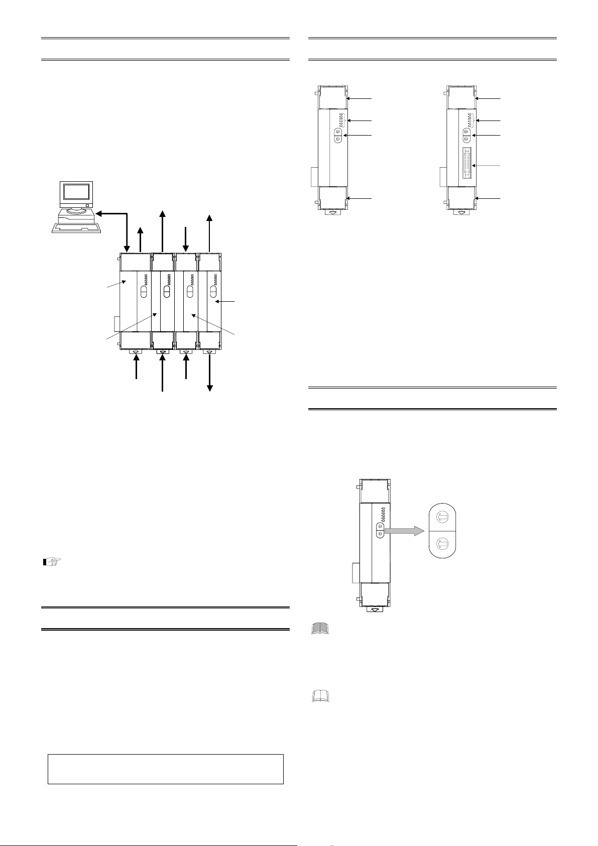
[X-DO-A] [X-DO-B]
Terminal cover
FAIL/RUN
RX/TX
EVENT1
EVENT2
EVENT3
EVTNT4
3
2
4
1
5
5 5
0
6
9
7
8
3
2
4
1
5
0
6
9
7
8
Indication lamps
ddress setting
switch
FAIL/RUN
RX/TX
EVENT1
EVENT2
EVENT3
EVTNT4
3
2
4
1
5
5 5
0
6
9
7
8
3
2
4
1
5
0
6
9
7
8
Terminal cover
Terminal cover
Indication lamps
ddress setting
switch
Digital output
connecter
Terminal cover
[Indication lamps]
FAIL/RUN
z
When normally: A green lamp turns on (RUN)
When abnormally: A red lamp turns on (FAIL)
RX/TX
z
During data send and receive: A green lamp turns on
EVENT 1 to 4
z
Event output ON: A green lamp turns on
Event 1 to 4 is assigned to every DO channel.
If several DO channels are assigned to one EVENT lamp, the
lamp is lit by the OR operation of outputs from each DO
channel.
4. COMMUNICATION SETTING
Set communication setting before mounting and wiring of SRX.
4.1 Module Address Setting
Set an address of module. For this setting, use a small blade
screwdriver.
FAIL/RUN
RX/TX
EVENT1
EVENT2
EVENT3
EVTNT4
• For Modbus, the value obtained by adding “1” to
the set address corresponds to the address used
Address setting switch
3
2
4
1
5
5 5
0
6
9
7
8
3
2
4
1
5
0
6
9
7
8
High-order digit
3
2
4
1
5
5 5
setting
0
6
9
7
8
(Set value × 10)
3
2
4
Low-order digit
1
5
0
6
setting
9
7
8
(Set value × 1)
Setting range: 0 to 99
(Factory set value: 00)
for the actual program.
• Set the module address such that it is different to
the other addresses on the same line. Otherwise,
problems or malfunction may result.
The above figure is X-DO-A module. The figure of
X-DO-B module is the same as a X-DO-A module.
2
IMS01N05-E1
Page 3

4.2 Protocol Selections and
Communication Speed Setting
With the DIP switch which there is on the right side of module,
select communication speed, data bit configuration, protocol and
termination resistor of internal data bus.
DIP switch
ON
ON
1 2 3 4 5 6 7 8
1 2 3 4 5 6 7 8
Right side
1 2 Communication speed
OFF OFF 2400 bps
ON OFF 9600 bps
OFF ON 19200 bps
ON ON 38400 bps
Factory set value: 9600 bps
3 4 5 Data bit configuration
OFF OFF OFF Data 7-bit, without parity *
OFF OFF ON Data 7-bit, Even parity *
OFF ON ON Data 7-bit, Odd parity *
ON OFF OFF Data 8-bit, without parity
ON OFF ON Data 8-bit, Even parity
ON ON ON Data 8-bit, Odd parity
When the Modbus communication protocol selected, this
*
setting becomes invalid.
Factory set value: Data 8-bit, without parity
6 Protocol selection
OFF RKC communication
ON Modbus
Factory set value: RKC communication
8 Internal data bus termination resistor setting
OFF Termination resistor OFF
ON Termination resistor ON
Factory set value: Termination resistor OFF
• Switch No. 7: OFF fixed (Don’t change this one)
• When two or more modules are connected on the
same line for their use, set DIP switches
corresponding to the switches, 1 to 6 on all of the
modules to the same positions. In addition, always
turn on the switch, 8 (with the internal bus
termination resistance connected) in module of
both ends.
• Be changed into communication time setting mode
by using switch No. 4, 5 and 6.
For communication time setting mode, see the
Type Controller SRX Communication Instruction
Manual (IMS01N01-E)
.
ON
OFF
Module
5. MOUNTING
To prevent electric shock or instrument failure,
always turn off the power before mounting or
removing the instrument.
5.1 Mounting Cautions
(1) This instrument is intended to be used under the following
environmental conditions.
[OVERVOLTAGE CATEGORY II, POLLUTION DEGREE 2]
(2) Avoid the following when selecting the mounting location.
Ambient temperature of less than −10 °C or more than +50 °C.
•
Ambient humidity of less than 5 % or more than 95 % RH.
•
Rapid changes in ambient temperature, which may cause
•
condensation.
Corrosive or inflammable gases.
•
Direct vibration or shock to the mainframe.
•
Water, oil, chemicals, vapor or steam splashes.
•
Excessive dust, salt or iron particles.
•
Excessive induction noise, static electricity, magnetic fields or
•
noise.
Direct air flow from an air conditioner.
•
Exposure to direct sunlight.
•
Excessive heat accumulation.
•
(3) Mounting consideration
Install the module 200 mm away from the main power line.
•
Ensure at least 50 mm space on top and bottom of the control
•
unit for maintenance and environmental reasons.
5.2 Dimensions
[X-DO-A]
[X-DO-B]
(Unit: mm)
125
5
(Unit: mm)
125
5
WARNING
!
(IEC61010-1)
110 6.8
30
78
124.3
110
78
6.8
30
IMS01N05-E1
3
Page 4

5.3 DIN rail Mounting
Mounting procedures
Pull down the mounting bracket at the bottom of the module.
1.
(A) Attach the hooks on the top of the module to the DIN rail
and push the lower section into place on the DIN rail. (B)
DIN rail
(B) Push
Mounting
bracket
Slide the mounting bracket up to secure the module to the
2.
DIN rail. (Fig. 2)
(A) Pull down
Fig. 1
5.4 Panel Mounting
Mounting procedures
Pull down the mounting bracket (A) until locked and that a
1.
mounting hole appears.
Prepare one mounting bracket per module (B) sold
2.
separately (KSRX-55) and then insert it in the rear of the
terminal board at top of the module until locked but a
mounting hole does not disappear.
Mount each module directly on the panel with screws which
3.
are inserted in the mounting holes of the top and bottom
mounting brackets.
Recommended tightening torque: 0.3 N⋅m (3 kgf⋅cm)
The customer needs to provide the M3 size screws.
Select the screw length that matches the mounting
panel.
(B) Insert
Mounting bracket
(Sold separately)
[KSRX-55]
Mounting
holes
Locked
Fig. 2
End Plate mounting
Hold tight both ends of the modules jointed together with the end
plates attached to the temperature control module [basic type]
and then fix the end plates with screws.
End Plate
For the conservation of the contact of connector, install a joint
*
connector cover (be attached to the
[basic type]) in module of both ends.
Temperature control module [basic type]
Joint connector cover *
temperature control
End Plate
module
Removing procedures
Pull down a mounting bracket with a blade screwdriver (A). Lift
the module from bottom, and take it off (B).
(A) Pull down
Mounting
30 ± 0.2
(Unit: mm)
dimensions
35.25 ± 0.2
0.2
±
130.5
M3
Module of 40.5 mm wide Module of 30 mm wide
5.5 Jointing Each Module
Up to 31 SRXs consisting of the each modules can be jointed
together. Joint these modules according to the following
procedure.
Jointing procedure
Mount the modules on the DIN rail and then joint these
1.
modules together with the joint connector while sliding the
relevant module.
Lift each of the joint tabs located at the top and bottom of the
2.
module and then insert it in the slot of the adjacent module to
fix these two modules.
For panel mounting, first joint each module and then
mount it on the panel.
4
(A) Pull down
(B) Lift and take off
Joint connector
Joint tab
There is one joint tab at each
of the top and bottom of on
module. Therefore, fix two
adjacent modules with these
two joint tabs.
When viewed
from top
Joint tab
insertion slot
IMS01N05-E1
Page 5

6. WIRING
p
To prevent electric shock or instrument failure, do
not turn on the power until all the wiring is
com
leted.
CAUTION
To avoid noise induction, keep input signal wire away from
instrument power line, load lines and power lines of other
electric equipment.
Terminal configuration
z
X-DO-A/X-DO-B (common)
WARNING
!
Digital output CH1 to 6
Circuit configuration
DO 1
DO 6
COM
DO 25
Load
Load
Load
24 V
DC
L
DO 3
3
COM
7
6
7 6 5 4
11 10 9 8
24 V
DC
11
COM
14
DO 12
L
10
Digital output CH7 to 12
Use the solderless terminal appropriate to the screw
size (M3).
5.9 mm or less
Pin layout of connector
z
X-DO-B
1
10
Digital output
CH13 to 28
Pin Nos. 1 and 6, and pin Nos. 11 and 16 are internally
connected, respectively.
IMS01N05-E1
L
DO 2
2
L
DO 6
3 2 1
14 13 12
DO 9
L
13
DO 11
L
1
2
3
11
4
5
20
6
7
8
9
10
L
DO 1
1
L
DO 5
5
L
DO 4
4
Upper-side
terminals
Lower-side
terminals
9
DO 8
L
12
L
8
DO 7
L
DO 10
Recommended tightening
0.4 N⋅m (4 kgf⋅cm)
torque:
COM
DO 13
DO 14
DO 15
DO 16
COM
DO 17
DO 18
DO 19
DO 20
24 V
DC
L
L
L
L
24 V
DC
L
L
L
L
11
12
13
14
15
16
17
18
19
20
COM
DO 21
DO 22
DO 23
DO 24
COM
DO 25
DO 26
DO 27
DO 28
24 V
DC
L
L
L
L
24 V
DC
L
L
L
L
DO 28
COM
Load
24 V DC
Connection example
z
Relay contact output (Relay terminal connection)
Relay terminal RT1S-OD16-24V-S
(manufactured by Matsushita
Electric Works, Ltd)
Connection cable
W-BQ-02
F +
DO 28
DO 27
DO 26
DO 25
DO 24
DO 23
DO 22
DO 21
DO 20
DO 19
DO 18
DO 17
DO 16
DO 15
DO 14
DO 13
24 V DC
L
E +
L
L
D +
L
C +
L
B +
L
A +
L
9 +
L
8 +
L
7 +
L
6 +
5 +
L
L
4 +
3 +
L
L
2 +
L
1 +
L
0 +
VCC
F −
E −
D −
C −
B −
A −
9 −
8 −
7 −
6 −
5 −
4 −
3 −
2 −
1 −
0 −
NC
GND
AC
(DC power supply is
possible.)
Independent common
is possible.
5
Page 6

z
Transistor output
(Connector terminal connection)
Connection cable
W-BQ-01
DO 28
DO 27
DO 26
DO 25
DO 24
DO 23
DO 22
DO 21
L
L
L
L
COM
L
L
L
L
COM
B10
B9
B8
B7
B6
B5
B4
B3
B2
B1
A10
A9
A8
A7
A6
A5
A4
A3
A2
A1
For the connection cable, use the RKC product (Sold
separately).
Cable type: W-BQ-01-3000 [Standard cable length: 3 m]
(For connector terminal connection)
W-BQ-02-3000 [Standard cable length: 3 m]
(For relay terminal connection)
Recommended connector terminal:
•
Manufactured by Matsushita Electric Works, Ltd
CT2-20 (DIN rail mounting type)
CT2-M-20 (direct mounting type)
Recommended relay terminal:
•
Manufactured by Matsushita Electric Works, Ltd
RT1S-OD16-24V-S
7. FUNCTIONS
Connector terminal CT2-20
(manufactured by Matsushita
Electric Works, Ltd)
DO 20
L
DO 19
L
DO 18
L
L
DO 17
COM
L
DO 16
DO 15
L
L
DO 14
DO 13
L
COM
24 V DC
8. SPECIFICATIONS
Outputs
Output type: Transistor output (sink type)
Number of outputs: X-DO-A: 12 points (6 points/common):
Digital output function
The signal of the following can be selected.
Temperature control (TIO) module
Digital input (DI) module
LED display
Number of display: 6 points
Display contents: Operation: RUN/FAIL lamp
Communications
Communication interface: Based on RS-485, EIA standard
Communication protocol: RKC communication or Modbus
Connection: Internal bus
Others
Power supply voltage: 24 V DC
Current consumption: X-DO-A: 70 mA max./module
Ambient temperature range:
Ambient humidity range: 5 to 95 %RH (Non condensing)
Weight: X-DO-A: Approx. 150 g
Rated load: 24 V DC
Maximum load current: 50 mA/point
ON voltage: 2 V max.
Terminal
X-DO-B: 28 points
Terminal: 12 points
(6 points/common)
Connector: 16 points
(4 points/common)
:
Burnout state, Event 1 state, Event 2 state,
Heater break alarm (HBA) state, Control
loop break alarm (LBA) state, Program
end state, Pattern end state, Wait state,
Time signal 1 to 16 output state
:
Input state of DI module CH1 to 28
Communication: RX/TX lamp
Event: EVENT1 to 4 lamps
(Supplied by temperature control
module [basic type])
X-DO-B: 90 mA max./module
10 to +50 °C
−
Absolute humidity:
MAX.W.C 29 g/m
3
dry air at 101.3 kPa
X-DO-B: Approx. 160 g
Contents of Digital Output Signal
Each status of the temperature control (TIO) module or the
digital input (DI) module is assigned to each DO channel as its
corresponding output signal.
Temperature control (TIO) module
Each status of the TIO module described in the following is
assigned to each DO channel.
Burnout state, Event 1 state, Event 2 state, Heater break alarm
(HBA) state, Control loop break alarm (LBA) state, Program end
state, Pattern end state, Wait state, Time signal 1 to 16 output
state
Digital input (DI) module
Each status of the DI module described in the following is
assigned to each DO channel.
Input state of DI module CH1 to 28
6
Modbus is a registered trademark of Schneider Electric.
z
Company names and product names used in this manual are the
z
trademarks or registered trademarks of the respective companies.
The first edition: OCT. 2002 [IMQ01]
RKC INSTRUMENT INC.
®
HEADQUARTERS:16-6, KUGAHARA 5-CHOME, OHTA-KU
TOKYO 146-8515 JAPAN
PHONE: 03-3751-9799 (+81 3 3751 9799)
E-mail: info@rkcinst.co.jp
FAX: 03-3751-8585 (+81 3 3751 8585)
IMS01N05-E1
 Loading...