

Page 1

A
.
Module Type Controller SRV
Temperature Control Module for DeviceNet
V-TIO-J/V-TIO-K
Instruction Manual
IMS01P10-E1
Thank you for purchasing this RKC product. In order to
achieve maximum performance and ensure proper operation
of your new instrument, carefully read all the instructions in
this manual. Please place this manual in a convenient
location for easy reference.
SYMBOLS
WARNING
CAUTION
An external protection device must be installed if
failure of this instrument could result in damage to
the instrument, equipment or injury to personnel.
All wiring must be completed before power is turned
on to prevent electric shock, fire or damage to
instrument and equipment.
This instrument must be used in accordance with the
specifications to prevent fire or damage to
instrument and equipment.
This instrument is not intended for use in locations
subject to flammable or explosive gases.
Do not touch high-voltage connections such as
power supply terminals, etc. to avoid electric shock.
RKC is not responsible if this instrument is repaired,
modified or disassembled by other than
factory-approved personnel. Malfunction can occur
and warranty is void under these conditions.
This is a Class A instrument. In a domestic environment,
this instrument may cause radio interference, in which
case the user may be required to take adequate measures.
: This mark indicates precautions that must be
taken if there is danger of electric shock, fire,
etc., which could result in loss of life or injury.
: This mark indicates that if these precautions
and operating procedures are not taken,
damage to the instrument may result.
: This mark indicates that all precautions should
!
be taken for safe usage.
: This mark indicates important information on
installation, handling and operating
procedures.
: This mark indicates supplemental information
on installation, handling and operating
procedures.
: This mark indicates where additional
information may be located.
WARNING
!
CAUTION
This instrument is protected from electric shock by
reinforced insulation. Provide reinforced insulation between
the wire for the input signal and the wires for instrument
power supply, source of power and loads.
Be sure to provide an appropriate surge control circuit
respectively for the following:
− If input/output or signal lines within the building are
longer than 30 meters.
− If input/output or signal lines leave the building,
regardless the length.
This instrument is designed for installation in an enclosed
instrumentation panel. All high-voltage connections such
as power supply terminals must be enclosed in the
instrumentation panel to avoid electric shock by operating
personnel.
All precautions described in this manual should be taken to
avoid damage to the instrument or equipment.
All wiring must be in accordance with local codes and
regulations.
All wiring must be completed before power is turned on to
prevent electric shock, instrument failure, or incorrect
action.
The power must be turned off before repairing work for
input break and output failure including replacement of
sensor, contactor or SSR, and all wiring must be
completed before power is turned on again.
To prevent instrument damage or failure, protect the power
line and the input/output lines from high currents with a
protection device such as fuse, circuit breaker, etc.
Prevent metal fragments or lead wire scraps from falling
inside instrument case to avoid electric shock, fire or
malfunction.
Tighten each terminal screw to the specified torque found
in the manual to avoid electric shock, fire or malfunction.
For proper operation of this instrument, provide adequate
ventilation for heat dispensation.
Do not connect wires to unused terminals as this will
interfere with proper operation of the instrument.
Turn off the power supply before cleaning the instrument.
Do not use a volatile solvent such as paint thinner to clean
the instrument. Deformation or discoloration will occur. Use
a soft, dry cloth to remove stains from the instrument.
To avoid damage to instrument display, do not rub with an
abrasive material or push front panel with a hard object.
Do not connect modular connectors to telephone line.
NOTICE
This manual assumes that the reader has a fundamental
knowledge of the principles of electricity, process control,
computer technology and communications.
The figures, diagrams and numeric values used in this
manual are only for purpose of illustration.
RKC is not responsible for any damage or injury that is
caused as a result of using this instrument, instrument
failure or indirect damage.
Periodic maintenance is required for safe and proper
operation of this instrument. Some components have a
limited service life, or characteristics that change over time.
Every effort has been made to ensure accuracy of all
information contained herein. RKC makes no warranty
expressed or implied, with respect to the accuracy of the
information. The information in this manual is subject to
change without prior notice.
No portion of this document may be reprinted, modified,
copied, transmitted, digitized, stored, processed or
retrieved through any mechanical, electronic, optical or
other means without prior written approval from RKC.
ll Rights Reserved, Copyright 2004, RKC INSTRUMENT INC
RKC INSTRUMENT INC.
®
Page 2
1. OUTLINE
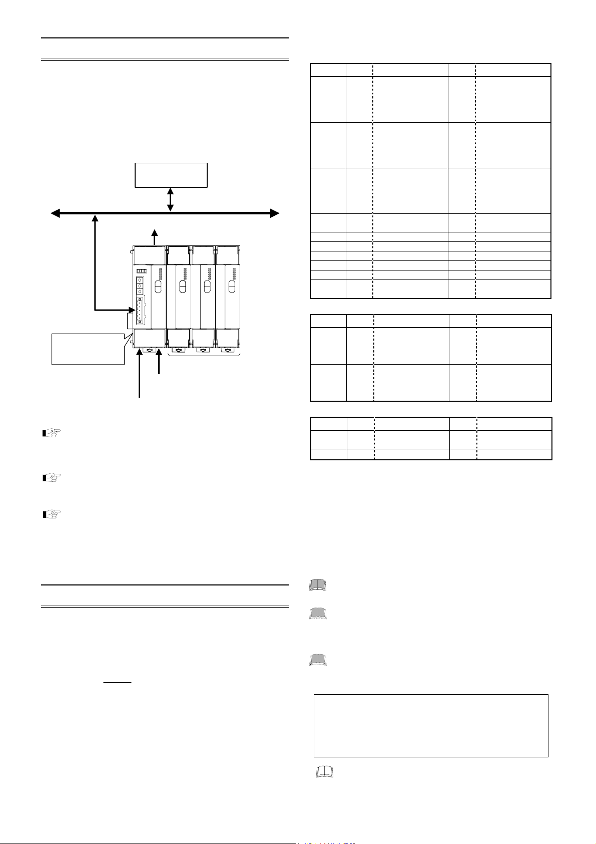
The temperature control module for DeviceNet V-TIO-J/V-TIO-K
can send and receive data to/from DeviceNet compatible
programmable controller (PLC) by the DeviceNet that is a
multi-vendor compatible open field network.
One V-TIO-J/V-TIO-K module enables temperature control
corresponding to two channels. It has power supply and
communication terminals in addition to temperature control input
and output terminals.
All data are set by communication.
Master
Slave
Temperature control
module for DeviceNet
V-TIO-J/V-TIO-K
Power supply
For details when dividing two or more temperature
control modules into some groups and then installed,
Programmable
controller (PLC)
Control output
Measured
(24 V DC)
input
DeviceNet
Usable modules:
•
Temperature control module
[Basic type]: V-TIO-A/V-TIO-C
•
Temperature control module
[Extension type]: V-TIO-B/V-TIO-D
(Up to 30 modules)
see the Module Type Controller SRV DeviceNet
Communication Instruction Manual (IMS01P11-E).
For details, see the Module Type Controller SRV
DeviceNet
(IMS01P11-E).
For host communication using host communication
terminals, see the Appendix B of Module Type
Communication Instruction Manual
Controller SRV DeviceNet Communication
Instruction Manual (IMS01P11-E) and the Module
Type Controller SRV Communication Instruction
Manual (IMS01P01-E).
2. PRODUCT CHECK
Before using this product, check each of the following:
• Model code
• Check that all of the accessories delivered are complete.
• Check that there are no scratch or breakage in external
appearance (case, front panel, or terminal, etc).
V–TIO– – N N N – N N – –
(1) (2) (3) (4) (5) (6) (7)
(1) Type
J: Module for DeviceNet, heat control
K: Module for DeviceNet, heat/cool control
(2) Control action (Each channel common code)
[For heat control]
F: PID action with autotuning (AT) (reverse action)
D: PID action with autotuning (AT) (direct action)
[For heat/cool control]
B: Heat/cool PID action with autotuning (AT) (air cooling)
W: Heat/cool PID action with autotuning (AT) (water cooling)
2
*
(3) Input range (Each channel common code)
[Thermocouple input]
Type Code Range Code Range
K K02 0 to 400 °C KB9 32 to 752 °F
K04 0 to 800 °C KB8 32 to 1472 °F
K16 −200 to +1372 °C KB7 −328 to +2501 °F
K09 0.0 to 400.0 °C KC2 32.0 to 752.0 °F
K35 −200.0 to +400.0 °C KC1 −328.0 to +752.0 °F
J J02 0 to 400 °C JC2 32 to 752 °F
J04 0 to 800 °C JC1 32 to 1472 °F
J15 −200 to +1200 °C JB9 −328 to +2192 °F
J09 0.0 to 400.0 °C JC4 32.0 to 752.0 °F
J27 −200.0 to +400.0 °C JC3 −328.0 to +752.0 °F
T T08 0 to 400 °C TB9 32 to 752 °F
T09 0 to 200 °C TC1 32 to 392 °F
T16 −200 to +400 °C TB8 −328 to +752 °F
T06 0.0 to 400.0 °C TC3 32.0 to 752.0 °F
T19 −200.0 to +400.0 °C TC2 −328.0 to +752.0 °F
E E01 0 to 800 °C EA8 32 to 1472 °F
E02 0 to 1000 °C EA7 32 to 1832 °F
S S05 0 to 1768 °C SA6 32 to 3214 °F
R R06 0 to 1768 °C RA6 32 to 3214 °F
N N02 0 to 1300 °C NA6 32 to 2372 °F
B B03 0 to 1800 °C BB1 32 to 3272 °F
PLⅡ A02 0 to 1390 °C AA6 32 to 2534 °F
W5Re/
W26Re
[RTD input]
Type Code Range Code Range
Pt100 D17 0 to 400 °C DC5 32 to 752 °F
D33 0 to 850 °C DC4 32 to 1562 °F
D16 0.0 to 400.0 °C DC7 32.0 to 752.0 °F
D28 −200.0 to +400.0 °C DC6 −328.0 to +752.0 °F
JPt100 P17 0 to 400 °C PC5 32 to 752 °F
P23 0 to 600 °C PC4 32 to 1112 °F
P16 0.0 to 400.0 °C PC7 32.0 to 752.0 °F
P28 −200.0 to +400.0 °C PC6 −328.0 to +752.0 °F
[Voltage/current input]
Voltage 201 0 to 100 mV DC 401 0 to 5 V DC
501 0 to 10 V DC 601 1 to 5 V DC
Current 701 0 to 20 mA DC 801 4 to 20 mA DC
W03 0 to 2300 °C WA9 32 to 4172 °F
Code Type Code Type
(4) Control output (CH1), (5) Control output (CH2)
M: Relay contact output V: Voltage pulse output 0/12 V DC
4: 0 to 5 V DC 5: 0 to 10 V DC 6: 1 to 5 V DC
7: 0 to 20 mA DC 8: 4 to 20 mA DC
(6) CT type (Each channel common code)
P: CTL-6-P-N (for 0 to 30 A) S: CTL-12-S56-10L-N (for 0 to 100 A)
(7) DeviceNet connector type
N: Open-style connector (Unshielded type)
1: Micro-style connector (Shield type)
For heat/cool PID control (V-TIO-K), input channel 2
becomes unused.
For heat/cool PID control (V-TIO-K), Control output
(CH1) corresponds to the heating output and
Control output (CH2) corresponds to the cooling
output.
Heater break alarm function can not be used when
control output is voltage/current output.
Accessories
Floppy disk (EDS file)................................................. 1
End Plate.................................................................... 2
Joint connector cover ................................................. 2
Instruction Manual (IMS01P10-E1)............................ 1
If any of the products are missing, damaged, or if your
manual is incomplete, please contact RKC sales office
or the agent.
IMS01P10-E1
Page 3

r
r
3. PARTS DESCRIPTION
Indication lamps 2
Node address
setting switch
DeviceNet communication
speed setting switch
DeviceNet connecto
[Open-style connector]
(COM.PORT)
FAIL/RUN
RX/TX
EVENT1
NS
EVENT2
MS
FAIL
RUN
EVENT3
EVENT4
MSD LSD DR
NODE ADDRESS
V+ CAN_H Drain CAN_L V−
COM. PORT
Joint connector
(Left side)
DeviceNet side Temperature control side
Front view of open-style connector type
FAIL/RUN
RX/TX
EVENT1
EVENT2
NET
FAIL
RUN
MOD
EVENT3
EVENT4
MSD LSD RATE
NODE ADDRESS
COM. PORT
DeviceNet connecto
[Micro-style connector]
(COM.PORT)
Front view of micro-style connector type
Indication
lamps 2
FAIL
RUN
FAIL/RUN
RX/TX
EVENT1
NS
MS
EVENT2
EVENT3
EVENT4
Temperature control sideDeviceNet side
[Indication lamps 1]
FAIL/RUN (for temperature control)
When normally: A green lamp turns on (RUN)
When abnormally: A red lamp turns on (FAIL)
RX/TX (for host communication using host communication
terminals)
During data send and receive: A green lamp turns on
EVENT 1 to 4
Display various states by setting.
ON state: A green lamp turns on
Display contents:
Event 1 state, Event 2 state, Comprehensive event state, Output state,
Control state, Execution segment state, Time signal state
[Indication lamps 2]
FAIL (for DeviceNet communication)
When abnormally: A red lamp turns on
Communication environment setting mode by the switch:
A red lamp flashes
RUN (for DeviceNet communication)
When normally: A green lamp turns on
Memory backup error: A green lamp flashes slowly
Module configuration error: A green lamp flashes slowly
Communication error: A green lamp flashes slowly
Data collection just after the power is turned on:
A green lamp flashes rapidly
NS or NET (Network status)
Network is operating normally, but communications have not yet
been established: A green lamp flashes
Terminal cover
Indication lamps 1
Module address
setting switch
Joint connector
(Right side)
Terminal cover
Connectors other than the
micro-style connector are
the same as those of the
open-style connector type.
However, only the following
names are different.
(A function is the same)
Indication lamps 2
•
Open-style connector:
NS, MS
Micro-style connector:
NET, MOD
DeviceNet communication
•
speed setting switch
Open-style connector: DR
Micro-style connector: RATE
Indication
lamps 1
Network is operating normally (communications established):
A green lamp turns on
I/O connection is timeout: A red lamp flashes
A fatal communications error has occurred
Network communications are not possible:
A red lamp turns on
MS or MOD (Module status)
When DeviceNet communication is normal:
A green lamp turns on
Module configuration error: A green lamp flashes
Memory backup error: A red lamp turns on
4. COMMUNICATION SETTING
Set communication setting before mounting and wiring of SRV.
CAUTION
Do not separate the module mainframe from the terminal
base with the power turned on. If separated, adjusted data
may be destroyed; control be stopped, and no return can be
made.
4.1 Address Setting
Node address setting
To identify each device connected to the network, it is necessary
to set a different address to each device (node). For the
DeviceNet, as it is possible to connect up to 64 devices including
a master to the network, node address (MAC ID) from 0 to 63
can be set.
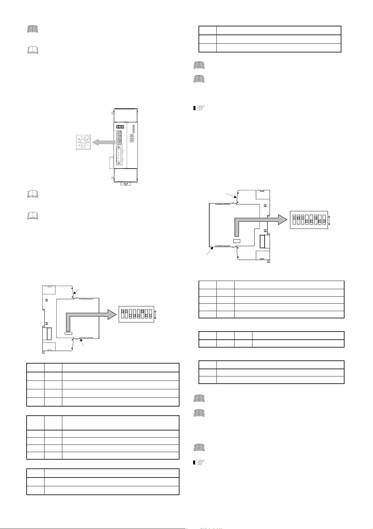
Module address setting
Set a module address (temperature control side). For this setting,
use a small blade screwdriver.
For this setting, use a small blade screwdriver.
Node address setting switch
MSD: High-order digit setting
(Set value ×10)
LSD: Low-order digit setting
(Set value ×1)
FAIL/RUN
RX/TX
EVENT1
EVENT2
NS
MS
FAIL
RUN
EVENT3
EVENT4
MSD LSD DR
NODE ADDRESS
V+ CAN_H Drain CAN_L V−
COM. PORT
Setting range: 0 to 63
(Factory set value: 63)
The above figure is open-style connector type. The
figure of micro-style connector type is the same as a
open-style connector type.
When any number exceeding 64 is set, the node
address number becomes “63.”
FAIL/RUN
RX/TX
EVENT1
EVENT2
NS
MS
FAIL
RUN
EVENT3
EVENT4
MSD LSD DR
NODE ADDRESS
V+ CAN_H Drain CAN_L V−
COM. PORT
Module address setting switch
High-order digit setting
(set value × 10)
Low-order digit setting
(set value × 1)
Setting range: 0 to 98
(Factory set value: 0)
Do not set “99” to a module address of the
temperature control side, as the module address of
DeviceNet side is fixed in “99.” Otherwise,
malfunction may result.
IMS01P10-E1
3
Page 4
Set the module address such that it is different to
the other addresses on the same line. Otherwise,
problems or malfunction may result.
The previous page figure is open-style connector type.
The figure of micro-style connector type is the same as
a open-style connector type.
4.2 DeviceNet Communication Setting
Communication speed setting
Set the communication speed of DeviceNet. For this setting, use
a small blade screwdriver.
DeviceNet communication
speed setting switch
Setting range: 0: 125 kbps
(Factory set value: 0)
The above figure is open-style connector type. The
figure of micro-style connector type is the same as a
open-style connector type.
When any number between 3 and 9 is set, the
communication speed becomes “500 kbps.”
Number of communication data items when
conducting polling I/O communication and host
communication protocol setting
With the DIP switch 1 which there is on the left side of module,
set the number of communication data items when conducting
DeviceNet polling I/O communication, host communication
and internal communication mode.
protocol
Factory set value: 38400 bps
Factory set value: 8 words
Factory set value: Modbus
Left side view (DeviceNet side)
1 2 Host communication (RS-485) speed
OFF OFF 2400 bps
ON OFF 9600 bps
OFF ON 19200 bps
ON ON 38400 bps
4 5 Number of communication data items when
conducting polling I/O communication
OFF OFF 8 words
ON OFF 26 words
OFF ON 46 words
ON ON 100 words
6 Host communication protocol selection
OFF RKC communication
ON Modbus
(DR or RATE)
1: 250 kbps
2: 500 kbps
Terminal base
Module mainframe
FAIL/RUN
RX/TX
EVENT1
NS
EVENT2
MS
FAIL
RUN
EVENT3
EVENT4
MSD LSD DR
NODE ADDRESS
CAN_H Drain CAN_L V
+
V
COM. PORT
−
DIP switch 1
ON
ON
1 2 3 4 5 6 7 8
1 2 3 4 5 6 7 8
ON
OFF
7 Internal communication mode selection
OFF DeviceNet communication mode
ON Host communication (RS-485) mode
Factory set value: DeviceNet communication mode
Switch No. 3: OFF fixed (Don’t change this one)
Switch No. 8: OFF fixed (Don’t change this one)
Switch No. 1, 2, 6 and 7 are used for the setting
related to host communication on the DeviceNet
side. When used only for DeviceNet communication,
do not change the factory set values.
For the host communication of DeviceNet side, see the
Appendix B of Module Type Controller SRV
DeviceNet Communication Instruction Manual
(IMS01P11-E).
4.3 Host Communication Setting
(temperature control side)
With the DIP switch 2 which there is on the right side of module,
the communication speed, data bit configuration, protocol, and
set
termination resistor of internal data bus
temperature control side.
Terminal base
Module mainframe
Right side view (Temperature control side)
1 2 Host communication (RS-485) speed
OFF OFF 2400 bps
ON OFF 9600 bps
OFF ON 19200 bps
ON ON 38400 bps
Factory set value: 38400 bps
3 4 5 Data bit configuration
ON OFF OFF Data 8-bit, without parity, Stop 1-bit
Factory set value: Data 8-bit, without parity, Stop 1-bit
6 Host communication protocol selection
OFF RKC communication
ON Modbus
Factory set value: Modbus
Switch No. 7: OFF fixed (Don’t change this one)
Switch No. 8: OFF fixed (Don’t change this one)
When connecting two or more modules (V-TIO-A,
V-TIO-B, V-TIO-C or V-TIO-D) to the module (V-TIO-J
or V-TIO-K), match all of the switch No. 1 to 6
settings with the internal settings of the module
(V-TIO-J or V-TIO-K).
When no host communication terminals are used, it
is not necessary to set the DIP switch 2.
For host communication using host communication
terminals, see the Appendix B of Module Type
Controller SRV DeviceNet Communication
Instruction Manual (IMS01P11-E) and the Module
Type Controller SRV Communication Instruction
Manual (IMS01P01-E).
for host communication of
DIP switch 2
ON
ON
1 2 3 4 5 6 7 8
1 2 3 4 5 6 7 8
ON
OFF
4
IMS01P10-E1
Page 5
5. MOUNTING
To prevent electric shock or instrument failure,
always turn off the power before mounting or
removing the instrument.
5.1 Mounting Cautions
(1) This instrument is intended to be used under the following
environmental conditions. (IEC61010-1)
[OVERVOLTAGE CATEGORY II, POLLUTION DEGREE 2]
(2) Use this instrument within the following ambient temperature
and ambient humidity.
• Allowable ambient temperature: −10 to +50 °C
• Allowable ambient humidity: 5 to 95 % RH
(Absolute humidity: MAX.W.C 29 g/m
(3) Avoid the following when selecting the mounting location.
• Rapid changes in ambient temperature, which may cause
condensation.
• Corrosive or inflammable gases.
• Direct vibration or shock to the mainframe.
• Water, oil, chemicals, vapor or steam splashes.
• Excessive dust, salt or iron particles.
• Excessive induction noise, static electricity, magnetic fields or
noise.
• Direct air flow from an air conditioner.
• Exposure to direct sunlight.
• Excessive heat accumulation.
(4) Mounting consideration
• Install the module 200 mm away from the main power line.
• Ensure at least 50 mm space on top and bottom of the control
unit for maintenance and environmental reasons.
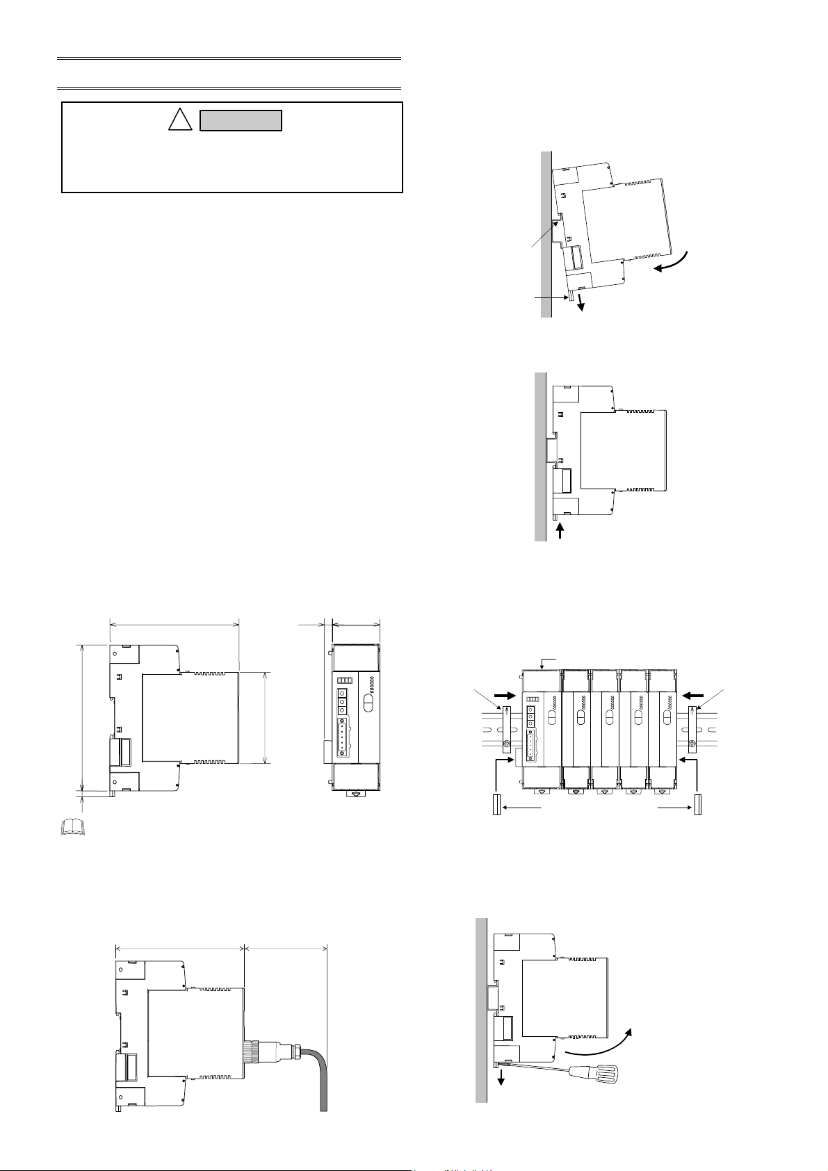
5.2 Dimensions
125
110
!
WARNING
78
3
dry air at 101.3 kPa)
(Unit: mm)
6.8
40.5
5.3 DIN rail Mounting
Mounting procedures
1. Pull down the mounting bracket at the bottom of the module
(A). Attach the hooks on the top of the module to the DIN rail
and push the lower section into place on the DIN rail (B).
DIN rail
(B) Push
Mounting
bracket
2. Slide the mounting bracket up to secure the module to the
DIN rail.
End Plate mounting
Hold tight both ends of the modules jointed together with the end
plates and then fix the end plates with screws. Even if only one
V-TIO-J/V-TIO-K module is used, also hold tight both ends of the
module with the end plates.
End Plate
(A) Pull down
Locked
V-TIO-J/V-TIO-K module
End Plate
5
The above figure is open-style connector type. The
figure of micro-style connector type is the same as a
open-style connector type.
Depth in connector mounting
Conduct installation in consideration of the sizes of the
connector and cable when connector-connected.
[Usage example of micro-style connector] (Unit: mm)
110
Approx. 100 *
* For open-style
connector:
Approx. 50 mm
IMS01P10-E1
Joint connector cover *
* For the conservation of the contact of connector, install a joint
connector cover in module of both ends.
Removing procedures
Pull down a mounting bracket with a blade screwdriver (A). Lift
the module from bottom, and take it off (B).
(B) Lift and take off
(A) Pull down
5
Page 6
r
)
(A)
−
A
−
−
A
3
e
5.4 Panel Mounting
Mounting procedures
1. Pull down the mounting bracket (A) until locked and that a
mounting hole appears.
2. Prepare one mounting bracket per module (B) sold
separately (KSRX-55) and then insert it in the rear of the
terminal board at top of the module until locked but a
mounting hole does not disappear.
3. Mount each module directly on the panel with screws which
are inserted in the mounting holes of the top and bottom
mounting brackets.
Recommended tightening torque: 0.3 N⋅m (3 kgf⋅cm)
The customer needs to provide the M3 size screws.
Select the screw length that matches the mounting
panel.
(B) Insert
Mounting
Mounting bracket
(Sold separately)
(A) Pull down
[KSRX-55]
30 ± 0.2
Mounting
holes
(Unit: mm)
dimensions
35.25 ± 0.2
0.2
±
M3
Module of 40.5 mm wide Module of 30 mm wide
130.5
5.5 Jointing Each Module
Up to 30 modules (V-TIO-A, V-TIO-B, V-TIO-C or /V-TIO-D) can
be connected to one module (V-TIO-J or V-TIO-K).
modules according to the following procedure.
Jointing procedures
1. Mount the modules on the DIN rail and then joint these
modules together with the joint connector while sliding the
relevant module.
2. Lift each of the joint tabs located at the top and bottom of the
module and then insert it in the slot of the adjacent module to
fix these two modules.
For panel mounting, first joint each module and then
mount it on the panel.
Joint connecto
Joint tab
There is one joint tab at each
of the top and bottom of on
module. Therefore, fix two
adjacent modules with these
two joint tabs.
6
Joint these
When viewed
from top
Joint tab
insertion slot
6. WIRING
To prevent electric shock or instrument failure, do not
turn on the power until all the wiring is completed.
6.1 Wiring Cautions
For thermocouple input, use the appropriate compensation
wire.
For RTD input, use low resistance lead wire with no
difference in resistance between the three lead wires.
To avoid noise induction, keep input signal wire away from
instrument power line, load lines and power lines of other
electric equipment.
If there is electrical noise in the vicinity of the instrument that
could affect operation, use a noise filter.
− Shorten the distance between the twisted power supply wire
pitches to achieve the most effective noise reduction.
− Always install the noise filter on a grounded panel.
Minimize the wiring distance between the noise filter output
and the instrument power supply terminals to achieve the
most effective noise reduction.
− Do not connect fuses or switches to the noise filter output
wiring as this will reduce the effectiveness of the noise filter.
Power supply wiring must be twisted and have a low voltage
drop.
For an instrument with 24 V power supply, supply power from
a SELV circuit.
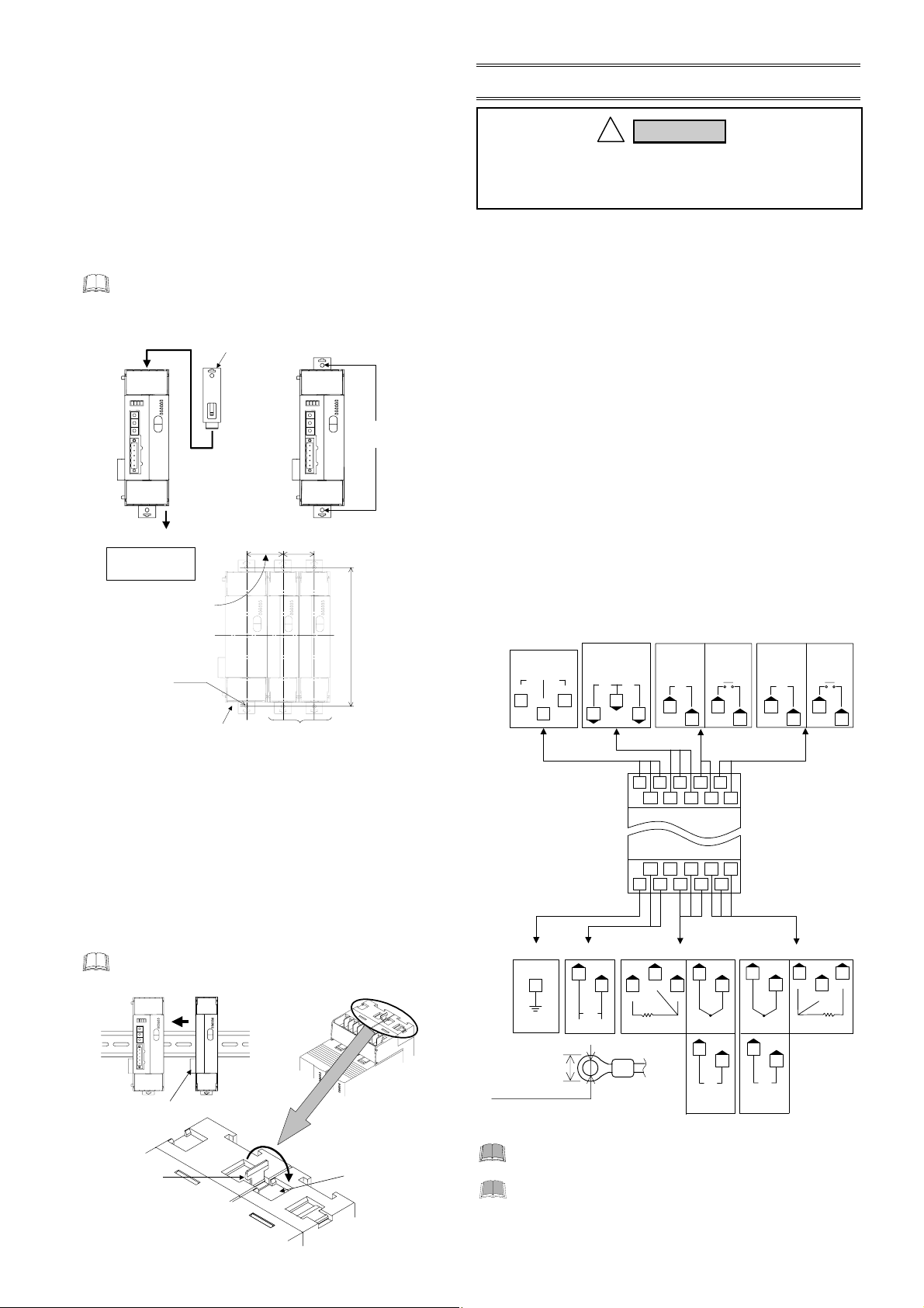
6.2 Terminal Configuration
Internal communicat ion
or
Host communication
RS-485
T/R
T/R(B
15
16
SG
17
Power supply
Ground
18
20
DC
+
FG
24 V
5.9 mm or less
.2 mm or mor
Recommended tightening torque:
0.4 N
⋅m (4 kgf⋅cm)
For heat/cool PID control (V-TIO-K), input channel 2
becomes unused.
For heat/cool PID control (V-TIO-K), Control output
(CH1) corresponds to the heating output and
Control output (CH2) corresponds to the cooling
output.
WARNING
!
CT input Control output 1 Control output 2
CT1
19
Voltage pulse/
Current/
Voltage
CT2
3
OUT1
+ −
2
67
16 15 3 2 1
17 7 6 5 4
18 11 10 9 8
20 19 14 13 12
Input channel 1
10
B
14 13
RTD1
RTD
B
Relay contact
5
10
TC1
+
Thermocouple
10
+
IN1
Voltage/
Voltage/
Current
Current
OUT1
NO
2
5
Upper-side terminal
Lower-side terminal
9
13
−
+
Thermocouple
9
13
+
−
Voltage/
Current
Voltage pulse/
Current/
Voltage
OUT2
−
+
1
4
Input channel 2
9
B
12
TC2
12
IN2
Relay contact
OUT2
1
12
B
RTD2
RTD
IMS01P10-E1
NO
4
8
Page 7
Heater break alarm function can not be used when
control output is voltage/current output.
Terminal No. 11 is not used.
Use the solderless terminal appropriate to the screw
size (M3).
7. SPECIFICATIONS
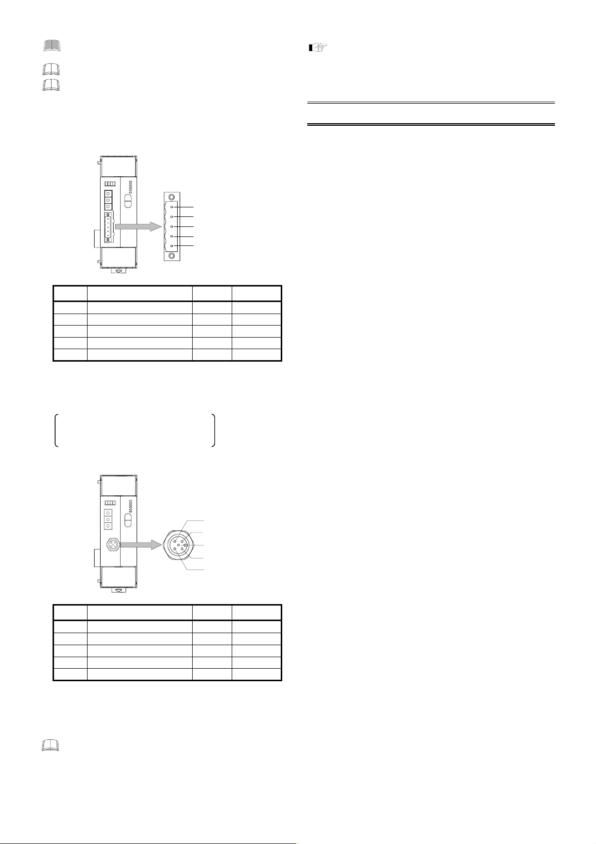
6.3 Pin Layout of Connector
Open-style connector
DeviceNet connector
Open-style connector
(COM. PORT)
1: V−
2: CAN_L
3: Drain
4: CAN_H
5: V+
Pin No. Signal name Symbol Cable color
1
Power supply, minus (−) V−
Black
2 Communication data, low CAN_L Blue
3 Shield Drain
4 Communication data, high CAN_H White
5
Power supply, plus (+) V+
Red
• Connection plugs
SRXDN-01 (Sold separately)
MSTB2.5/5-STF-5.08AUM (PHOENIX CONTACT, Inc.) or
equal
Multi-drop type (recommended models)
TMSTBP2.5/5-STF-5.08AUM
(PHOENIX CONTACT, Inc.)
Micro-style connector
DeviceNet connector
Micro-style connector
(COM. PORT)
3: V−
2: V+
5: CAN_L
1: Drain
4: CAN_H
Pin No. Signal name Symbol Cable color
1 Shield Drain
2
Power supply, plus (+) V+
3
Power supply, minus (−) V−
Red
Black
4 Communication data, high CAN_H White
5 Communication data, low CAN_L Blue
• Connection socket
Recommended models: SACC-M12FS-5CON-PG 9-M
(PHOENIX CONTACT, Inc.)
(This socket is a type to use thin cable.)
Use the communication cable (thick cable or thin cable)
that matched specification of DeviceNet.
By thickness of a cable to use and connection method,
usable connection connector type is different.
Inputs
Number of inputs: 2 points
Input type:
Sampling cycle: 500 ms
PV bias: −Input span to +Input span
CT input: 2 points
Number of outputs: 2 points
Output type:
Number of controls: 2 points
Control method: Brilliant PID control
Additional function: Autotuning function
Events
Number of events: 2 points/channel
Event type: Temperature event:
Number of HBA: 2 points
Setting range: 0.0 to 100.0 A (0.0 A: OFF)
Additional function: Number of event delay times:
For cable specifications, connection method and vendor,
see the home page of ODVA (Open DeviceNet Vender
Association).
URL: http://www.odva.org
Isolated between each channel:
Thermocouple input, Voltage (low) input
Not isolated between each channel:
RTD input, Voltage (high) input,
Current input
• Thermocouple K, J, T, S, R, E, B, N (JIS-C1602-1995)
PLII (NBS)
W5Re/W26Re (ASTM-E988-96)
• RTD: Pt100 (JIS-C1604-1997)
JPt100 (JIS-C1604-1989, Pt100 of
JIS-C1604-1981)
• Voltage (low): 0 to 100 mV
• Voltage (high): 0 to 5 V, 0 to 10 V, 1 to 5 V
• Current: 0 to 20 mA, 4 to 20 mA
(Input impedance: 250 Ω)
0.0 to 30.0 A (CTL-6P-N) or
0.0 to 100.0 A (CTL-12-S56-10L-N)
Outputs
(Isolated between input and output, and
between output and power supply)
•Relay contact: 250 V AC, 3 A (Resistive load)
1a contact
Electrical life: 300,000 times or more
(Rated load)
•Voltage pulse: 0/12 V DC
(Load resistance 600 Ω or more)
•Current: 0 to 20 mA DC, 4 to 20 mA DC
(Load resistance 600 Ω or less)
•Voltage: 0 to 5 V DC, 0 to 10 V DC, 1 to 5 V DC
(Load resistance 1 kΩ or more)
Control action
Reverse action or direct action is
selectable (Specify when ordering)
Heat/cool control is selectable
(Specify when ordering)
Deviation high, Deviation low,
Deviation high/low, Band,
Process high, Process low
Heater break alarm,
Control loop break alarm,
Burnout, Temperature rise completion
Heater break alarm (HBA) function
1 to 255 times
Continued on the next page.
IMS01P10-E1
7
Page 8

]
Continued from the previous page.
Control loop break alarm (LBA) function
Number of LBA: 2 points
LBA time: 1 to 7200 seconds
LBA deadband (LBD) setting:
0 to Input span
DeviceNet communication
Protocol: DeviceNet
Connection method: Multi-drop connection,
T-branch connection
(Terminating resistor [121Ω, 1/4 W] is
necessary)
Communication speed: 125 kbps, 250 kbps, or 500 kbps
Error control: CRC error, Node address (MAC ID)
duplication check
Maximum number of connection nodes:
64 (including master)
Host communication
(using host communication terminals)
Communication interface: Based on RS-485, EIA standard
Communication protocol: RKC communication
(ANSI X3.28 subcategory 2.5, A4)
or Modbus
Maximum connections: 32 instruments * maximum including
a host computer
As each of the DeviceNet board and
*
temperature control board incorporated in the
V-TIO-J/V-TIO-K module is handled as one unit,
one V-TIO-J/V-TIO-K module corresponds two
Others
modules.
Power supply voltage: 24 V DC
Power supply voltage range:
21.6 V DC to 26.4 V DC
Current consumption: 170 mA max./module
Allowable ambient temperature:
−10 to +50 °C
Allowable ambient humidity:
5 to 95 %RH
Absolute humidity:
MAX.W.C 29 g/m
Weight: Open-style connector type:
Approx. 250 g
Micro-style connector type:
Approx. 270 g
3
dry air at 101.3 kPa
DeviceNet is a registered trademark of Open DeviceNet Vender Association, Inc.
Modbus is a registered trademark of Schneider Electric.
Company names and product names used in this manual are the trademarks or registered trademarks of the respective companies.
This product has been self-tested by RKC found to comply with ODVA Conformance Test Software V17.
The first edition: AUG. 2004[IMQ00
HEADQUARTERS: 16-6, KUGAHARA 5-CHOME, OHTA-KU TOKYO 146-8515 JAPAN
RKC INSTRUMENT INC.
®
AUG. 2004 IMS01P10-E1
PHONE: 03-3751-9799 (+81 3 3751 9799) E-mail: info@rkcinst.co.jp
FAX: 03-3751-8585 (+81 3 3751 8585)
 Loading...