


2PS2B-.85
Table of contents
 Loading...
OPERATING INSTRUCTIONS
and PARTS LIST for
RIX GAS COMPRESSOR
MODEL NO. 2PS2B-.85
(FOR SPECIFIC MODEL NUMBER INFORMATION,
SEE TABLE ON FOLLOWING PAGE.)
APPLICABLE TO S/N# 10369 AND ABOVE

GENERIC MANUAL FOR
2PS2B-.85 COMPRESSOR
This is a generic manual for all of the RIX Model 2PS2B-.85 compressors. The various compressors
are summarized in the table below.
SPECIFIC PACKAGE INFORMATION FOR THE
RIX INDUSTRIES' 2PS2B-.85 COMPRESSOR
FLOW HP SPEED SUCTION VOLTAGE MODEL *
PRESSURE FREQUENCY NUMBER
(SCFH) (RPM) PSIG (HZ)
120 V - 60 HZ 2PS2B-.85-L
30 to 60 1-1/2 190 30 to 70
240 V - 50 HZ 2PS2B-.85-L50
120 V - 60 HZ 2PS2B-.85-H
60 to 120 1-1/2 390 30 to 70 240 V - 60 HZ 2PS2B-.85-HH
240 V - 50 HZ 2PS2B-.85-H50
Generally speaking the compressors are identical except for differences in the motors, motor starters,
sheaves, etc. The parts applicable to each different model are clearly indicated in the parts list.
Overload heaters may vary from compressor to compressor.
Part numbers appropriate to the different options are indicated in the parts list.
* Some compressors may have been invoiced using a different model number. All represented
models use the 2PS nomenclature.

TABLE OF CONTENTS
PART I
Table of Contents ................................. i-ii
Serial Number Page .............................. iii
Safety Summary .................................... iv
Warranty .................................................. v
Chapter Page Chapter Page
1. GENERAL INFORMATION ................................ 1-1 5. TROUBLESHOOTING........................................ 5-1
1-1 Introduction .................................................... 1-1 5-1 Troubleshooting............................................ 5-1
1-2 Equipment Description ................................... 1-1
1-3 Oxygen Cleanliness ........................................ 1-3 6. CORRECTIVE MAINTENANCE ........... 6-1
2. OPERATION........................................................... 2-1 6-1 Introduction .................................................. 6-1
6-2 Belt & Pulleys............................................... 6-1
2-1 Introduction .................................................... 2-1 6-3 Cylinder Heads ............................................. 6-2
2-2 Controls & Indicators ..................................... 2-1 6-4 Compressor Valves.......................................6-3
2-3 Operating Procedures ..................................... 2-2 6-5 Cylinders ...................................................... 6-5
6-6 Crankcase ..................................................... 6-5
3. FUNCTIONAL DESCRIPTION ........................... 3-1 6-7 Piston Rings.................................................. 6-5
6-8 Piston Assembly ........................................... 6-6
3-1 Major Components ......................................... 3-1 6-9 Main Bearings .............................................. 6-7
6-10 Connecting Rod Bearings............................. 6-7
4. SCHEDULED MAINTENANCE .......................... 4-1 6-11 Belt Drive ..................................................... 6-8
6-12 Heat Exchangers........................................... 6-9
4-1 Introduction .................................................... 4-1 6-13 Piston Clearance Adjustment........................ 6-9
4-2 Filter Cleaning ................................................ 4-2
4-3 Compression Valves Inspection
& Reconditioning ........................................ 4-2 7. PARTS LIST.......................................................... 7-1
4-4 Pressure Relief Valves.................................... 4-2
4-5 Belt Adjustment.............................................. 4-3 7-1 Introduction & Compressor Parts List.......... 7-1
4-6 Gas System Piping.......................................... 4-3 7-2 Accessories Parts List & Option Packages... 7-3
4-7 Bearing Inspection.......................................... 4-4 7-3 Plumbing Parts List ...................................... 7-7
4-8 Piston Ring Replacement................................ 4-4 7-4 Hardware Parts List ...................................... 7-8
LIST OF TABLES
Table Title Page Table Title Page
1-1 Reference Data....................................................... 1-2 6-2 Relief Valve Settings ......................................... 6-10
1-2 Equipment, Accessories & Documents Supplied .. 1-2 6-3 Operating Temperatures .................................... 6-10
2-1 Operating Procedures - Operator Start................... 2-2 6-4 Wrench Torques (Oiled Threads)...................... 6-10
2-2 Operating Procedures - Modes of Operation ......... 2-3 6-5 Control Switch Settings ..................................... 6-10
2-3 Operating Procedures - Operator Stop................... 2-3 6-6 Clearances & Tolerances ................................... 6-11
2-4 Operating Procedures - Emergency Stop............... 2-4 7-1 Compressor Parts List.......................................... 7-1
4-1 Preventive Maintenance......................................... 4-1 7-2 Accessory Parts List & Option Packages ............ 7-3
5-1 Compressor Troubleshooting Guide...................... 5-1 7-3 Plumbing Parts List ............................................. 7-7
6-1 Normal Operating Pressure Ranges..................... 6-10 7-4 Hardware Parts List ............................................. 7-8
i

TABLE OF CONTENTS
PART I (Continued)
LIST OF CHARTS
Chart Title Page Chart Title Page
5-1 High Pressure Troubles.......................................... 5-2 5-6 Unusual Vibration Troubles ................................ 5-4
5-2 Low Pressure Troubles .......................................... 5-2 5-7 Inability to Start Compressor............................... 5-5
5-3 High Temperature Troubles................................... 5-3 5-8 Inability to Restart Compressor ........................... 5-5
5-4 Reduced Capacity Troubles ................................... 5-3 5-9 Inability to Stop Compressor ............................... 5-6
5-5 Unusual Noise Troubles ........................................ 5-4
LIST OF ILLUSTRATIONS
Figure Title Page Figure Title Page
1-1 2PS2B Oxygen Booster ........................................ 1-4 7-1 2PS2B Cross Section ........................................... 7-9
1-1a 2PS2B Oxygen Booster ........................................ 1-5 7-2 2nd Stage Valve Assembly................................ 7-10
1-1b 2PS2B Oxygen Booster ........................................ 1-6 7-3 1
st
Stage Piston Assembly.................................. 7-11
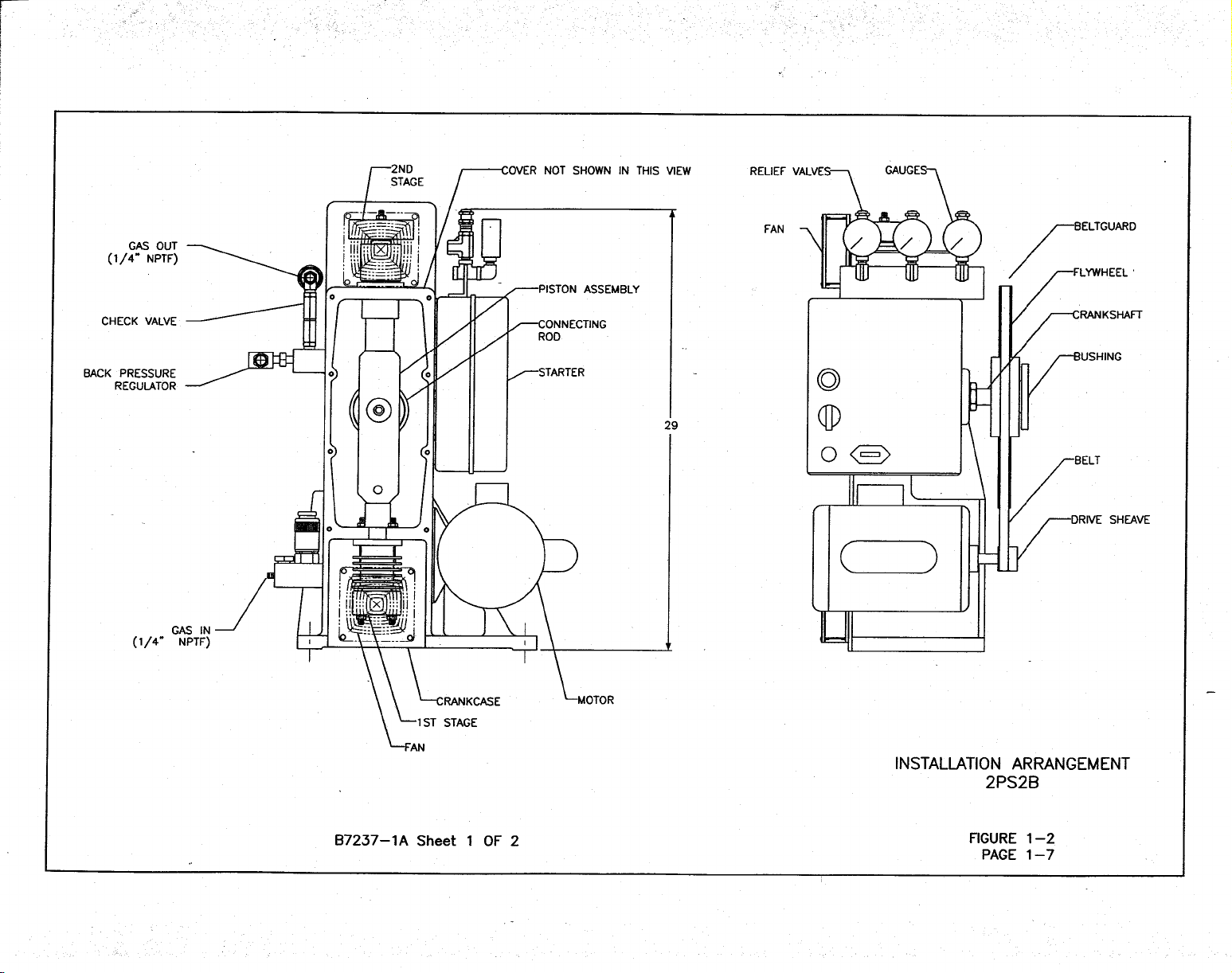
1-2 Install Arrangement ............................................... 1-7 7-4 1
st
Stage Valve Assembly .................................. 7-12
1-2a Install Arrangement ............................................... 1-8 7-5 2
nd
Stage Piston Assembly................................. 7-13
3-1 Compressor Assembly ........................................... 3-2 7-6 Accessories Drawing......................................... 7-14
3-2 Flow Schematic...................................................... 3-3 7-7a Plumbing Installation, Suction........................... 7-15
3-3 Electric Schematic ................................................. 3-4 7-7b Plumbing Installation, 1
st
Stage Discharge ........ 7-16
3-4 Wiring Diagram ..................................................... 3-5 7-7c Plumbing Installation, 2
nd
Stage Discharge ....... 7-17
TABLE OF CONTENTS
PART II
MANUFACTURER'S DRAWING AND TECHNICAL INFORMATION FOR:
Title Drawing Number
Pressure Switches: Inlet and Discharge..................................................................A8029A
ii

SERIAL NUMBER PAGE
This manual is applicable to all
RIX Industries
Model 2PS2B-.85 Oxygen Compressors
bearing one of the following serial numbers:
10369 AND ABOVE
iii

SAFETY SUMMARY
The following is a general safety precaution that is not related to any specific procedure and
therefore does not appear elsewhere in this publication. This is a recommended precaution that
personnel must understand and apply during many phases of operation and maintenance:
KEEP AWAY FROM LIVE CIRCUITS. Operating personnel must at all times
observe all safety regulations. Do not
replace components or make adjustments inside
the electrical enclosures with the voltage supply turned on.
The following WARNINGS and CAUTIONS appear in this manual and are
repeated here for emphasis.
CAUTION
Do not operate if safety guards are damaged or
removed.(Pg. 1-1)
CAUTION
Do not attempt any repair without first cutting off
power at the main breaker switch and consulting
cleanliness requirements. In automatic mode, the
compressor may start at any time.(Pg. 1-1)
CAUTION
Check relief valves for correct operation at regular
periods. Do not reset for any pressure other than that
stamped on the valve body.(Pg. 1-1)
CAUTION
Do not bypass the pressure switches. This would
eliminate safety features and could result in damage
to the compressor (Pg. 1-1)
WARNING
Do not touch discharge gas lines from the cylinders.
These are hot and can cause serious burns(Pg. 1-1)
WARNING
To prevent FIRE, SERIOUS INJURY, and/or
DEATH, it is the User’s responsibility to ensure all
parts used in the compression assembly, gas
plumbing of this RIX Oxygen compressor and any
other existing portions of the gas stream that may be
exposed during the installation of new or replacement
parts are cleaned for Oxygen Service prior to
installation.
Any work to be done on the compressor where the
gas stream may be exposed must be done in
accordance with safe Oxygen Equipment handling
procedures.
No attempt should be made to work on the machine
without full knowledge of Oxygen equipment
handling and the potential hazards of contamination.
Factory Oxygen cleaned parts are denoted by an “X”
prefix at the beginning of the part number. It is the
User’ s responsibility to maintain the cleanliness of
factory cleaned parts and any other existing portions
of the gas stream that may be exposed during the
initial installation, start up, or during installation of
replacement parts.
RIX Industries recommends the customer establish a
procedure for working with oxygen machinery.
Refer to Compressed Gas Association, Inc.
publication number CGA G-4.1, Cleaning Equipment
for Oxygen Service.
WARNING
Before performing any of the scheduled maintenance
tasks in Chapter 4, the compressor should be shut off
and tagged Out of Service. This is to prevent an
inadvertent start which could cause injury to
personnel or damage to the equipment. After
completing the maintenance action, the compressor
should be restored to full operation and the tags
removed.(Pg. 4-1)
WARNING
Discharge pipes, fittings, and port areas can cause
painful burns if touched. Always exercise caution
around the compressor when it is running or has
recently been run.(Pg. 2-1, 2-2)
WARNING
The compressor may start at any time when in
automatic mode. Before attempting any repairs or
adjustments: de-energize the machine by pushing the
STOP button, disconnect power to the system (to
avoid shock hazard), vent pressure by opening hand
valves down stream and give the discharge piping
time to cool down. Discharge lines are hot and can
cause burns.(Pg. 4-1, 6-1)
WARNING
Hot discharge lines can produce painful burns. Be
careful to avoid making contact with hot pipes while
performing tests and repairs.(Pg. 4-3)
iv

RIX INDUSTRIES’
COMPRESSOR WARRANTY
RIX Industries warrants all 2PS2B-.85 Compressors as follows:
Twelve (12) months of operation or eighteen (18) months from date of shipment
or 2,000 hours of operation, whichever occurs first, covering materials and workmanship.
Warranty does not cover normal wear or consequential damages.
RIX certifies that all oxygen compressors have been test run on pure oxygen gas at
desired pressures and flow rates and that the compressors are oxygen clean at shipment.
Purchaser takes full responsibility for all components added to the compressor package
that could contaminate the gas stream causing a failure
All warranty work conducted at RIX facilities at Sparks, Nevada, USA or
Benicia, California, USA, at RIX’s discretion. All freight and/or transportation charges
are to be paid by purchaser.
v

CHAPTER 1
GENERAL INFORMATION
SAFETY PRECAUTIONS
The following safety precautions apply to the RIX 2PS2B-.85 Compressor.
Proper attention to safety should be maintained whenever operating or servicing
this equipment. A complete listing of safety precautions is given in the Safety
Summary on Page iv.
Do not operate if safety guards are damaged or removed.
Do not touch discharge gas lines from the cylinders. These are hot and can cause
serious burns.
Do not attempt any repair without first cutting off power at the main breaker
switch and consulting cleanliness requirements.
Check relief valves for correct operation at regular periods. Do not reset for any
pressure other than that stamped on valve body.
Do not bypass pressure switches. This would eliminate safety features and could
result in damage to the compressor.
1-1 INTRODUCTION
1-1.1 PURPOSE. The intent of this manual is to provide information pertinent to the
operation, maintenance and installation of the high pressure, oil-less, air cooled compressor, RIX
Model 2PS2B-.85.
1-1.2 SCOPE. This publication sets forth requirements and procedures for the
operation, maintenance and installation of this subject equipment. It also includes descriptive
data and tests necessary to achieve a functional understanding of the compressor operation
together with its associated flow and control circuitry.
1-2 EQUIPMENT DESCRIPTION
1-2.1 INTENDED USE. The subject compressor system is designed for use to provide
high pressure Oxygen for storage or liquification.
1-2.2 OPERATING CHARACTERISTICS. Each compressor produces 2250 psig, 30-
120 SCFH oil-less Oxygen at a crankshaft speed of 190-390 RPM with 30-70 psig inlet pressure.
Each compressor is a reciprocating, two stage opposed, single acting design powered by a 1-1/2
HP motor through a belt drive.
1-1

Table 1-1. Reference Data
Descriptive Data High pressure, air cooled compressor package, RIX Industries
oil-less, reciprocating, two stage Oxygen compressor.
Functional Characteristics 1-1/2 HP motor 30-120 SCFH Oxygen output at 2250 psig
pressure with low suction pressure, and high discharge
pressure safety shutdown features.
Capabilities & Limitations Continuous duty, air cooled, non-lubricated. Not suitable for
wet or explosive gasses.
Rated Outputs 30-120 SCFH Oxygen at 2250 psig pressure, 190 or 390 RPM,
100˚F Oxygen inlet temperature, 30-70 psig inlet pressure, and
dry gas.
Designed to operate from 35˚ to 105˚F ambient with up to 100
percent relative humidity, and deliver gas at 130˚F maximum.
Power Required 1-1/2 HP 120V 190 RPM 60 Hz 12 Amps 2PS2B-.85-L
1-1/2 HP 230V 190 RPM 50 Hz 6 Amps 2PS2B-.85-L50
1-1/2 HP 120V 390 RPM 60 Hz 19 Amps 2PS2B-.85-H
1-1/2 HP 230V 390 RPM 60 Hz 10 Amps 2PS2B-.85-HH
1-1/2 HP 230V 390 RPM 50 Hz 14 Amps 2PS2B-.85-H50
Table 1-2. Equipment, Accessories and Documents Supplied
Item Name or Nomenclature
Overall
Dimension
Uncrated
Weight & Volume
Compressor Length 23 in. Weight - 150 lbs.
Width 14 in. Volume - 5.4 cu. ft.
Height 29 in.
Operation, Maintenance &
Installation Manual
8.5" x 11"
Weight - 1 lb.
1-2

1.3 OXYGEN CLEANLINESS
The RIX 2PS2B-.85 Oxygen Compressor is specially designed and built to safely process pure
Oxygen Gas without oxidation or combustion. All compressor parts have been thoroughly
cleaned and inspected. Assembly is done in a special cleaning facility and clean room
environment with extreme care taken to prevent any combustibles from entering the system.
WARNING
To prevent FIRE, SERIOUS INJURY, and/or DEATH, it is the User’s responsibility to ensure
all parts used in the compression assembly, gas plumbing of this RIX Oxygen compressor and
any other existing portions of the gas stream that may be exposed during the installation of new
or replacement parts are cleaned for Oxygen Service prior to installation.
Any work to be done on the compressor where the gas stream may be exposed must be done in
accordance with safe Oxygen Equipment handling procedures.
No attempt should be made to work on the machine without full knowledge of Oxygen
equipment handling and the potential hazards of contamination.
Factory Oxygen cleaned parts are denoted by an “X” prefix at the beginning of the part number.
It is the User’s responsibility to maintain the cleanliness of factory cleaned parts and any other
existing portions of the gas stream that may be exposed during the initial installation, start up, or
during installation of replacement parts.
RIX Industries recommends the customer establish a procedure for working with oxygen
machinery. Refer to Compressed Gas Association, Inc. publication number CGA G-4.1,
Cleaning Equipment for Oxygen Service.
1-3


CHAPTER 2
OPERATION
2-1 INTRODUCTION
2-1.1 GENERAL INFORMATION. Built-In safety features, which automatically shut
down the compressor if suction pressure is too low or excessive pressure is reached in the second
stage discharge line, are included in the system. The low pressure switch senses the pressure in
the suction line. The high pressure switch senses the pressure in the discharge line from the
aftercooler. Pressure gauges are utilized to measure suction pressure and first and second stage
discharge pressures. The gauges left to right are suction pressure, 1st stage pressure and 2nd
stage (or discharge) pressure. See Figure 1-1 and Figure 1-2.
2.2 CONTROLS & INDICATORS
2-2.1 ELECTRIC POWER. The motor controller must be wired to a source of power
by a competent electrician in accordance with local and federal codes. Make sure the
compressor package is properly grounded. See Electrical Schematic, Figure 3-3.
2-2.2 SAFETY VALVES. Pressure relief valves are provided after each stage. These
valves prevent an accidental over-pressurization of the system. The first stage relief valve is set
for 700 psig; the second stage is set for 2500 psig. The relief valves are mounted behind their
respective gauges. There is an inlet relief valve, set at 75 psig.
WARNING
Discharge pipes, fittings, and port areas can cause painful burns if
touched. Always exercise caution around the compressor when it
is running or has recently run.
2-2.3 PRESSURE SWITCHES. The compressor will automatically shutdown when the
discharge pressure reaches 2250 psig and will restart when it drops (to approximately 1900 psi).
Similarly, when the inlet pressure drops to 30 psig the compressor will stop, and
will re-start automatically when it rises again (to approximately 33 psig).
The actuation point of each switch may be adjusted although the re-set dead band,
the amount of pressure increase or decrease to reset the switch, is not adjustable.
2-2.4 PRESSURE INDICATORS. Pressure gauges measure the inlet pressure and the
first and second stage discharge pressures.
Sensing Point Normal Pressure Range
Inlet 30-70 Psig
First Stage Discharge 350-600 Psig
Second Stage Discharge 1500-2200 Psig
2-2.5 BACK PRESSURE VALVE. This valve is factory set at 1500 psi and needs no
adjustment. If necessary the valve can be adjusted by loosening the jam nut and turning the set
screw in or out with a hex wrench. The valve is located in the discharge piping prior to the
check valve. See Figure 1-1a.
2-1

2-3 OPERATING PROCEDURES
2-3.1 GENERAL. The operator should read and understand the procedures outlined in
Table 2-1 through Table 2-4 prior to starting the compressor. The following tables outline the
steps necessary for starting and stopping the compressor under both normal and emergency
conditions.
WARNING
Discharge pipes, fittings, and port areas can cause painful burns if
touched. Always exercise caution around the compressor when it
is running or has recently run.
Table 2-1. Operating Procedures - Operator Start
Sequences of Steps Taken to Place
Explanation of Operation
Initial Safety Requirements
Remove beltguard and rotate the compressor flywheel by
hand. Visually check to see that there are no obstructions
in the way of moving parts or other indications of disorder
or disrepair. Replace beltguard.
Connection of Accessory
Equipment Necessary for
Operations
Permanent installations should have all necessary electrical
wiring and piping in place. Piping must be installed in
accordance with safe oxygen handling procedures.
Instructions for Obtaining or
Confirming Critical Inputs.
Confirm that electrical power is available for running the
compressor.
Control Settings and Adjustment
Necessary prior to Turn-on
As necessary (customer interfacing). Inlet pressure
adjusted and set (minimum 30 psig, maximum 70 psig).
Milestones Verify inlet pressure on inlet gauge.
Visual or Audible Observations A slight hissing may occur as inlet gas escapes past the
compressor rings.
Operator Checks and
Adjustments
Check for leaks.
Operator's Maintenance Actions
and Schedules
Service compressor according to guidelines set forth in
Chapter 4.
2-2

Table 2-2. Operating Procedures - Modes of Operation
Sequences of Steps Taken to Make
Explanation of Operation the Equipment Operational
Initial Safety Requirements See Table 2-1 for all steps related to normal start-up.
Connection of Accessory
Equipment Necessary for
Operations
Confirm that compressor is properly connected to suction
and discharge piping. (Verify all connections were made in
accordance with Safe Oxygen Equipment Handling
Procedures).
Instructions for Obtaining or
Confirming Critical Inputs
Verify proper power hook up. Verify proper inlet pressure.
Control Settings and
Adjustments Necessary Prior to
Turn-on
Inlet pressure set 30 psig minimum, 70 psig maximum.
Determination of Operational
Readiness
Make sure all safety devices are in place.
Milestones Put selector switch to AUTO
Visual or Audible Observations First and 2nd Stage pressures rise. Brief knocking sound
lasting less than 10 seconds. Fans (if equipped) start.
Operator Checks & Observations Verify nominal operating pressures. See Table 6-1.
Table 2-3. Operating Procedures - Operator Stop
Sequences of Steps Taken to Shut
Explanation of Operation the Equipment Down
Initial Safety Requirements
Determine that operation of the compressor is no longer
required.
Connection of Accessory
Equipment Necessary for
Operations
None.
Instructions for Obtaining or
Confirming Critical Inputs.
None.
Control Settings and
Adjustments Necessary prior to
Turn-off.
None.
Determination of Operational
Readiness.
Compressor may be shut off at any time.
2-3

Milestone Put selector switch to OFF.
Visual or Audible Observations Observe that motor and compressor wind down and cease
running. Observe fans (if equipped) stop.
Operator's Maintenance Actions
and Schedules
Shut off main electrical supply. Service compressor
according to guidelines set forth in Chapter 4.
Table 2-4. Operating Procedures - Emergency Stop
Sequences of Steps Taken to Shut
Explanation of Operation the Equipment Down
Initial Safety Requirements None.
Connection of Accessory
Equipment Necessary for
Operations
None.
Instructions for Obtaining or
Confirming Critical Inputs
None.
Control Settings and
Adjustments Necessary prior to
Shutdown
None.
Determination of Operational
Readiness
None.
Milestones Shut compressor off by putting selector switch to OFF on
motor controller.
Visual or Aural Observations Verify that motor and compressor have stopped. Verify
fans (if equipped) have stopped.
Operator Checks and
Adjustments
Bleed pressure by loosening a fitting upstream of back
pressure valve.
Operator's Maintenance Actions
and Schedule.
None. Return unit to normal operation after emergency is
over.
2-4

CHAPTER 3
FUNCTIONAL DESCRIPTION
3-1 MAJOR COMPONENTS
3-1.1 COMPRESSOR ASSEMBLY. (Figure 3-1) The compressor is an air cooled
reciprocating, oil-less, two cylinder, two stage, single-acting, opposed design. The two compression
cylinders consist of a 1st stage piston of 1-1/4" diameter, and a 2nd stage 1/2" with a 2" piston stroke.
The 1st stage piston assembly is the heart of the compressor. The piston assembly has the 1st stage on the
bottom end and the 2nd stage on the top. The pistons for these cylinders use self - lubricating TFE or
Teflon
®
plastic rings. Linear motion is imparted to the piston assembly from the rotary crankshaft by
means of a connecting rod attached to the piston which alternately compresses in its respective cylinder.
The 1st stage rider rings guide one end of the assembly while the 1-3/4" diameter rider ring on the 2nd
stage end guides the other. The main bearings and connecting rod bearings are all sealed, grease packed
for life, and self-lubricating. The compressor valves are stainless steel reed type, normally closed and
pressure-activated open.
3-1.2 SENSING INDICATORS. Sensing devices are provided for safety and to aid the
operator in troubleshooting.
3-1.2.1 PRESSURE GAUGES. Pressure gauges are utilized to monitor suction pressure as
well as first and second stage discharge pressures.
3-1.3 RELIEF VALVES. Two pressure relief valves are located in the gas system, one after
each stage. There is also be a relief valve set at 75 psi in the suction piping. These serve to prevent
damage to the cylinders and gas lines should excessive pressure build up. The relief valves are preset to
700 and 2500 psi. When the pressure of the gas on the area of the relief valve disc exceeds the spring
load, the disc is lifted and the gas relieves to atmosphere. When the pressure is below the rating for the
valve, the disc remains seated and no gas escapes.
3-1.4 AIR COOLING SYSTEM. The compressor is provided with two stainless steel heat
exchangers mounted next to the crankcase: each cools the gas after it has been compressed in its
respective stage. Each heat exchanger is made up of stainless steel tubing coils and is sized for passive or
forced air cooling depending on compressor horsepower.
3-l.5 DRIVE MOTOR. A 1-1/2 HP motor is used to power the compressor through a belt
drive.
3-1.6 BACK PRESSURE VALVE. A back pressure valve is located in the discharge piping.
This valve is provided to maintain a minimum pressure of 1500 psi on the 2nd stage floating piston. The
pressure is required to hold this free floating piston against its piston rod so that the piston will not hit
against the valve stop in the 2nd stage head.
3-1.7 FILTER. An interstage filter keeps the system relatively free from small material
particles. The mesh size is 140 micron.
3-1.8 PRESSURE SWITCHES. Two pressure switches are provided. One for low suction
pressure, the other for high discharge pressure. The suction pressure switch is normally open and closes
when the inlet pressure is above 28 psig. If suction pressure drops below this point the compressor will
shutdown. The discharge pressure switch is normally closed. The compressor starts and stops
automatically under control of these switches.
3-1
 Loading...