

Page 1

OPERATING INSTRUCTIONS
and PARTS LIST for
RIX GAS COMPRESSOR
MODEL NO. 2PS2B-.85
(FOR SPECIFIC MODEL NUMBER INFORMATION,
SEE TABLE ON FOLLOWING PAGE.)
APPLICABLE TO S/N# 10369 AND ABOVE
Page 2

GENERIC MANUAL FOR
2PS2B-.85 COMPRESSOR
This is a generic manual for all of the RIX Model 2PS2B-.85 compressors. The various compressors
are summarized in the table below.
SPECIFIC PACKAGE INFORMATION FOR THE
RIX INDUSTRIES' 2PS2B-.85 COMPRESSOR
FLOW HP SPEED SUCTION VOLTAGE MODEL *
PRESSURE FREQUENCY NUMBER
(SCFH) (RPM) PSIG (HZ)
120 V - 60 HZ 2PS2B-.85-L
30 to 60 1-1/2 190 30 to 70
240 V - 50 HZ 2PS2B-.85-L50
120 V - 60 HZ 2PS2B-.85-H
60 to 120 1-1/2 390 30 to 70 240 V - 60 HZ 2PS2B-.85-HH
240 V - 50 HZ 2PS2B-.85-H50
Generally speaking the compressors are identical except for differences in the motors, motor starters,
sheaves, etc. The parts applicable to each different model are clearly indicated in the parts list.
Overload heaters may vary from compressor to compressor.
Part numbers appropriate to the different options are indicated in the parts list.
* Some compressors may have been invoiced using a different model number. All represented
models use the 2PS nomenclature.
Page 3

TABLE OF CONTENTS
PART I
Table of Contents ................................. i-ii
Serial Number Page .............................. iii
Safety Summary .................................... iv
Warranty .................................................. v
Chapter Page Chapter Page
1. GENERAL INFORMATION ................................ 1-1 5. TROUBLESHOOTING........................................ 5-1
1-1 Introduction .................................................... 1-1 5-1 Troubleshooting............................................ 5-1
1-2 Equipment Description ................................... 1-1
1-3 Oxygen Cleanliness ........................................ 1-3 6. CORRECTIVE MAINTENANCE ........... 6-1
2. OPERATION........................................................... 2-1 6-1 Introduction .................................................. 6-1
6-2 Belt & Pulleys............................................... 6-1
2-1 Introduction .................................................... 2-1 6-3 Cylinder Heads ............................................. 6-2
2-2 Controls & Indicators ..................................... 2-1 6-4 Compressor Valves.......................................6-3
2-3 Operating Procedures ..................................... 2-2 6-5 Cylinders ...................................................... 6-5
6-6 Crankcase ..................................................... 6-5
3. FUNCTIONAL DESCRIPTION ........................... 3-1 6-7 Piston Rings.................................................. 6-5
6-8 Piston Assembly ........................................... 6-6
3-1 Major Components ......................................... 3-1 6-9 Main Bearings .............................................. 6-7
6-10 Connecting Rod Bearings............................. 6-7
4. SCHEDULED MAINTENANCE .......................... 4-1 6-11 Belt Drive ..................................................... 6-8
6-12 Heat Exchangers........................................... 6-9
4-1 Introduction .................................................... 4-1 6-13 Piston Clearance Adjustment........................ 6-9
4-2 Filter Cleaning ................................................ 4-2
4-3 Compression Valves Inspection
& Reconditioning ........................................ 4-2 7. PARTS LIST.......................................................... 7-1
4-4 Pressure Relief Valves.................................... 4-2
4-5 Belt Adjustment.............................................. 4-3 7-1 Introduction & Compressor Parts List.......... 7-1
4-6 Gas System Piping.......................................... 4-3 7-2 Accessories Parts List & Option Packages... 7-3
4-7 Bearing Inspection.......................................... 4-4 7-3 Plumbing Parts List ...................................... 7-7
4-8 Piston Ring Replacement................................ 4-4 7-4 Hardware Parts List ...................................... 7-8
LIST OF TABLES
Table Title Page Table Title Page
1-1 Reference Data....................................................... 1-2 6-2 Relief Valve Settings ......................................... 6-10
1-2 Equipment, Accessories & Documents Supplied .. 1-2 6-3 Operating Temperatures .................................... 6-10
2-1 Operating Procedures - Operator Start................... 2-2 6-4 Wrench Torques (Oiled Threads)...................... 6-10
2-2 Operating Procedures - Modes of Operation ......... 2-3 6-5 Control Switch Settings ..................................... 6-10
2-3 Operating Procedures - Operator Stop................... 2-3 6-6 Clearances & Tolerances ................................... 6-11
2-4 Operating Procedures - Emergency Stop............... 2-4 7-1 Compressor Parts List.......................................... 7-1
4-1 Preventive Maintenance......................................... 4-1 7-2 Accessory Parts List & Option Packages ............ 7-3
5-1 Compressor Troubleshooting Guide...................... 5-1 7-3 Plumbing Parts List ............................................. 7-7
6-1 Normal Operating Pressure Ranges..................... 6-10 7-4 Hardware Parts List ............................................. 7-8
i
Page 4

TABLE OF CONTENTS
PART I (Continued)
LIST OF CHARTS
Chart Title Page Chart Title Page
5-1 High Pressure Troubles.......................................... 5-2 5-6 Unusual Vibration Troubles ................................ 5-4
5-2 Low Pressure Troubles .......................................... 5-2 5-7 Inability to Start Compressor............................... 5-5
5-3 High Temperature Troubles................................... 5-3 5-8 Inability to Restart Compressor ........................... 5-5
5-4 Reduced Capacity Troubles ................................... 5-3 5-9 Inability to Stop Compressor ............................... 5-6
5-5 Unusual Noise Troubles ........................................ 5-4
LIST OF ILLUSTRATIONS
Figure Title Page Figure Title Page
1-1 2PS2B Oxygen Booster ........................................ 1-4 7-1 2PS2B Cross Section ........................................... 7-9
1-1a 2PS2B Oxygen Booster ........................................ 1-5 7-2 2nd Stage Valve Assembly................................ 7-10
1-1b 2PS2B Oxygen Booster ........................................ 1-6 7-3 1st Stage Piston Assembly.................................. 7-11
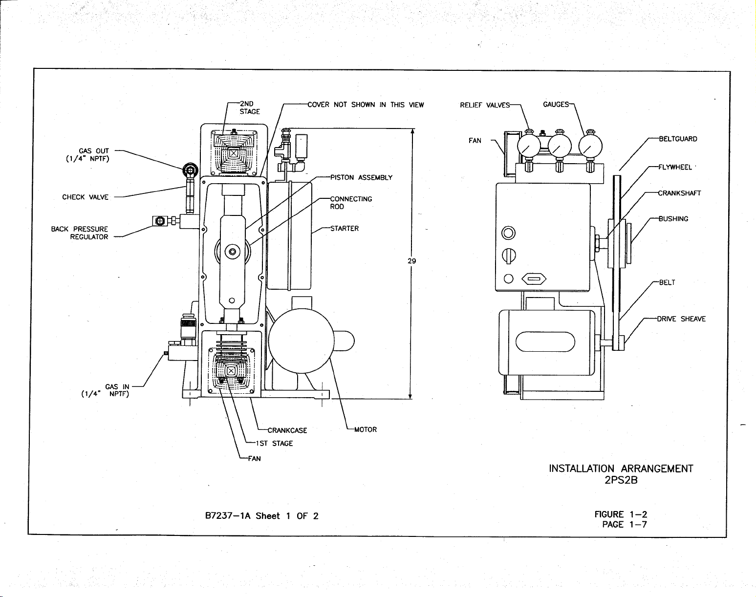
1-2 Install Arrangement ............................................... 1-7 7-4 1
1-2a Install Arrangement ............................................... 1-8 7-5 2
3-1 Compressor Assembly ........................................... 3-2 7-6 Accessories Drawing......................................... 7-14
3-2 Flow Schematic...................................................... 3-3 7-7a Plumbing Installation, Suction........................... 7-15
3-3 Electric Schematic ................................................. 3-4 7-7b Plumbing Installation, 1
3-4 Wiring Diagram ..................................................... 3-5 7-7c Plumbing Installation, 2
st
Stage Valve Assembly .................................. 7-12
nd
Stage Piston Assembly................................. 7-13
st
Stage Discharge ........ 7-16
nd
Stage Discharge ....... 7-17
TABLE OF CONTENTS
PART II
MANUFACTURER'S DRAWING AND TECHNICAL INFORMATION FOR:
Title Drawing Number
Pressure Switches: Inlet and Discharge..................................................................A8029A
ii
Page 5

SERIAL NUMBER PAGE
This manual is applicable to all
RIX Industries
Model 2PS2B-.85 Oxygen Compressors
bearing one of the following serial numbers:
10369 AND ABOVE
iii
Page 6

SAFETY SUMMARY
The following is a general safety precaution that is not related to any specific procedure and
therefore does not appear elsewhere in this publication. This is a recommended precaution that
personnel must understand and apply during many phases of operation and maintenance:
KEEP AWAY FROM LIVE CIRCUITS. Operating personnel must at all times
observe all safety regulations. Do not
replace components or make adjustments inside
the electrical enclosures with the voltage supply turned on.
The following WARNINGS and CAUTIONS appear in this manual and are
repeated here for emphasis.
CAUTION
Do not operate if safety guards are damaged or
removed.(Pg. 1-1)
CAUTION
Do not attempt any repair without first cutting off
power at the main breaker switch and consulting
cleanliness requirements. In automatic mode, the
compressor may start at any time.(Pg. 1-1)
CAUTION
Check relief valves for correct operation at regular
periods. Do not reset for any pressure other than that
stamped on the valve body.(Pg. 1-1)
CAUTION
Do not bypass the pressure switches. This would
eliminate safety features and could result in damage
to the compressor (Pg. 1-1)
WARNING
Do not touch discharge gas lines from the cylinders.
These are hot and can cause serious burns(Pg. 1-1)
WARNING
To prevent FIRE, SERIOUS INJURY, and/or
DEATH, it is the User’s responsibility to ensure all
parts used in the compression assembly, gas
plumbing of this RIX Oxygen compressor and any
other existing portions of the gas stream that may be
exposed during the installation of new or replacement
parts are cleaned for Oxygen Service prior to
installation.
Any work to be done on the compressor where the
gas stream may be exposed must be done in
accordance with safe Oxygen Equipment handling
procedures.
No attempt should be made to work on the machine
without full knowledge of Oxygen equipment
handling and the potential hazards of contamination.
Factory Oxygen cleaned parts are denoted by an “X”
prefix at the beginning of the part number. It is the
User’ s responsibility to maintain the cleanliness of
factory cleaned parts and any other existing portions
of the gas stream that may be exposed during the
initial installation, start up, or during installation of
replacement parts.
RIX Industries recommends the customer establish a
procedure for working with oxygen machinery.
Refer to Compressed Gas Association, Inc.
publication number CGA G-4.1, Cleaning Equipment
for Oxygen Service.
WARNING
Before performing any of the scheduled maintenance
tasks in Chapter 4, the compressor should be shut off
and tagged Out of Service. This is to prevent an
inadvertent start which could cause injury to
personnel or damage to the equipment. After
completing the maintenance action, the compressor
should be restored to full operation and the tags
removed.(Pg. 4-1)
WARNING
Discharge pipes, fittings, and port areas can cause
painful burns if touched. Always exercise caution
around the compressor when it is running or has
recently been run.(Pg. 2-1, 2-2)
WARNING
The compressor may start at any time when in
automatic mode. Before attempting any repairs or
adjustments: de-energize the machine by pushing the
STOP button, disconnect power to the system (to
avoid shock hazard), vent pressure by opening hand
valves down stream and give the discharge piping
time to cool down. Discharge lines are hot and can
cause burns.(Pg. 4-1, 6-1)
WARNING
Hot discharge lines can produce painful burns. Be
careful to avoid making contact with hot pipes while
performing tests and repairs.(Pg. 4-3)
iv
Page 7

RIX INDUSTRIES’
COMPRESSOR WARRANTY
RIX Industries warrants all 2PS2B-.85 Compressors as follows:
Twelve (12) months of operation or eighteen (18) months from date of shipment
or 2,000 hours of operation, whichever occurs first, covering materials and workmanship.
Warranty does not cover normal wear or consequential damages.
RIX certifies that all oxygen compressors have been test run on pure oxygen gas at
desired pressures and flow rates and that the compressors are oxygen clean at shipment.
Purchaser takes full responsibility for all components added to the compressor package
that could contaminate the gas stream causing a failure
All warranty work conducted at RIX facilities at Sparks, Nevada, USA or
Benicia, California, USA, at RIX’s discretion. All freight and/or transportation charges
are to be paid by purchaser.
v
Page 8

CHAPTER 1
GENERAL INFORMATION
SAFETY PRECAUTIONS
The following safety precautions apply to the RIX 2PS2B-.85 Compressor.
Proper attention to safety should be maintained whenever operating or servicing
this equipment. A complete listing of safety precautions is given in the Safety
Summary on Page iv.
Do not operate if safety guards are damaged or removed.
Do not touch discharge gas lines from the cylinders. These are hot and can cause
serious burns.
Do not attempt any repair without first cutting off power at the main breaker
switch and consulting cleanliness requirements.
Check relief valves for correct operation at regular periods. Do not reset for any
pressure other than that stamped on valve body.
Do not bypass pressure switches. This would eliminate safety features and could
result in damage to the compressor.
1-1 INTRODUCTION
1-1.1 PURPOSE. The intent of this manual is to provide information pertinent to the
operation, maintenance and installation of the high pressure, oil-less, air cooled compressor, RIX
Model 2PS2B-.85.
1-1.2 SCOPE. This publication sets forth requirements and procedures for the
operation, maintenance and installation of this subject equipment. It also includes descriptive
data and tests necessary to achieve a functional understanding of the compressor operation
together with its associated flow and control circuitry.
1-2 EQUIPMENT DESCRIPTION
1-2.1 INTENDED USE. The subject compressor system is designed for use to provide
high pressure Oxygen for storage or liquification.
1-2.2 OPERATING CHARACTERISTICS. Each compressor produces 2250 psig, 30120 SCFH oil-less Oxygen at a crankshaft speed of 190-390 RPM with 30-70 psig inlet pressure.
Each compressor is a reciprocating, two stage opposed, single acting design powered by a 1-1/2
HP motor through a belt drive.
1-1
Page 9

Table 1-1. Reference Data
Descriptive Data High pressure, air cooled compressor package, RIX Industries
oil-less, reciprocating, two stage Oxygen compressor.
Functional Characteristics 1-1/2 HP motor 30-120 SCFH Oxygen output at 2250 psig
pressure with low suction pressure, and high discharge
pressure safety shutdown features.
Capabilities & Limitations Continuous duty, air cooled, non-lubricated. Not suitable for
wet or explosive gasses.
Rated Outputs 30-120 SCFH Oxygen at 2250 psig pressure, 190 or 390 RPM,
100˚F Oxygen inlet temperature, 30-70 psig inlet pressure, and
dry gas.
Designed to operate from 35˚ to 105˚F ambient with up to 100
percent relative humidity, and deliver gas at 130˚F maximum.
Power Required 1-1/2 HP 120V 190 RPM 60 Hz 12 Amps 2PS2B-.85-L
1-1/2 HP 230V 190 RPM 50 Hz 6 Amps 2PS2B-.85-L50
1-1/2 HP 120V 390 RPM 60 Hz 19 Amps 2PS2B-.85-H
1-1/2 HP 230V 390 RPM 60 Hz 10 Amps 2PS2B-.85-HH
1-1/2 HP 230V 390 RPM 50 Hz 14 Amps 2PS2B-.85-H50
Table 1-2. Equipment, Accessories and Documents Supplied
Item Name or Nomenclature
Overall
Dimension
Uncrated
Weight & Volume
Compressor Length 23 in. Weight - 150 lbs.
Width 14 in. Volume - 5.4 cu. ft.
Height 29 in.
Operation, Maintenance &
Installation Manual
8.5" x 11"
Weight - 1 lb.
1-2
Page 10

1.3 OXYGEN CLEANLINESS
The RIX 2PS2B-.85 Oxygen Compressor is specially designed and built to safely process pure
Oxygen Gas without oxidation or combustion. All compressor parts have been thoroughly
cleaned and inspected. Assembly is done in a special cleaning facility and clean room
environment with extreme care taken to prevent any combustibles from entering the system.
WARNING
To prevent FIRE, SERIOUS INJURY, and/or DEATH, it is the User’s responsibility to ensure
all parts used in the compression assembly, gas plumbing of this RIX Oxygen compressor and
any other existing portions of the gas stream that may be exposed during the installation of new
or replacement parts are cleaned for Oxygen Service prior to installation.
Any work to be done on the compressor where the gas stream may be exposed must be done in
accordance with safe Oxygen Equipment handling procedures.
No attempt should be made to work on the machine without full knowledge of Oxygen
equipment handling and the potential hazards of contamination.
Factory Oxygen cleaned parts are denoted by an “X” prefix at the beginning of the part number.
It is the User’s responsibility to maintain the cleanliness of factory cleaned parts and any other
existing portions of the gas stream that may be exposed during the initial installation, start up, or
during installation of replacement parts.
RIX Industries recommends the customer establish a procedure for working with oxygen
machinery. Refer to Compressed Gas Association, Inc. publication number CGA G-4.1,
Cleaning Equipment for Oxygen Service.
1-3
Page 11

Page 12

Page 13

Page 14
Page 15

Page 16

CHAPTER 2
OPERATION
2-1 INTRODUCTION
2-1.1 GENERAL INFORMATION. Built-In safety features, which automatically shut
down the compressor if suction pressure is too low or excessive pressure is reached in the second
stage discharge line, are included in the system. The low pressure switch senses the pressure in
the suction line. The high pressure switch senses the pressure in the discharge line from the
aftercooler. Pressure gauges are utilized to measure suction pressure and first and second stage
discharge pressures. The gauges left to right are suction pressure, 1st stage pressure and 2nd
stage (or discharge) pressure. See Figure 1-1 and Figure 1-2.
2.2 CONTROLS & INDICATORS
2-2.1 ELECTRIC POWER. The motor controller must be wired to a source of power
by a competent electrician in accordance with local and federal codes. Make sure the
compressor package is properly grounded. See Electrical Schematic, Figure 3-3.
2-2.2 SAFETY VALVES. Pressure relief valves are provided after each stage. These
valves prevent an accidental over-pressurization of the system. The first stage relief valve is set
for 700 psig; the second stage is set for 2500 psig. The relief valves are mounted behind their
respective gauges. There is an inlet relief valve, set at 75 psig.
WARNING
Discharge pipes, fittings, and port areas can cause painful burns if
touched. Always exercise caution around the compressor when it
is running or has recently run.
2-2.3 PRESSURE SWITCHES. The compressor will automatically shutdown when the
discharge pressure reaches 2250 psig and will restart when it drops (to approximately 1900 psi).
Similarly, when the inlet pressure drops to 30 psig the compressor will stop, and
will re-start automatically when it rises again (to approximately 33 psig).
The actuation point of each switch may be adjusted although the re-set dead band,
the amount of pressure increase or decrease to reset the switch, is not adjustable.
2-2.4 PRESSURE INDICATORS. Pressure gauges measure the inlet pressure and the
first and second stage discharge pressures.
Sensing Point Normal Pressure Range
Inlet 30-70 Psig
First Stage Discharge 350-600 Psig
Second Stage Discharge 1500-2200 Psig
2-2.5 BACK PRESSURE VALVE. This valve is factory set at 1500 psi and needs no
adjustment. If necessary the valve can be adjusted by loosening the jam nut and turning the set
screw in or out with a hex wrench. The valve is located in the discharge piping prior to the
check valve. See Figure 1-1a.
2-1
Page 17

2-3 OPERATING PROCEDURES
2-3.1 GENERAL. The operator should read and understand the procedures outlined in
Table 2-1 through Table 2-4 prior to starting the compressor. The following tables outline the
steps necessary for starting and stopping the compressor under both normal and emergency
conditions.
WARNING
Discharge pipes, fittings, and port areas can cause painful burns if
touched. Always exercise caution around the compressor when it
is running or has recently run.
Table 2-1. Operating Procedures - Operator Start
Sequences of Steps Taken to Place
Explanation of Operation
Initial Safety Requirements
Remove beltguard and rotate the compressor flywheel by
hand. Visually check to see that there are no obstructions
in the way of moving parts or other indications of disorder
or disrepair. Replace beltguard.
Connection of Accessory
Equipment Necessary for
Operations
Instructions for Obtaining or
Confirming Critical Inputs.
Control Settings and Adjustment
Necessary prior to Turn-on
Permanent installations should have all necessary electrical
wiring and piping in place. Piping must be installed in
accordance with safe oxygen handling procedures.
Confirm that electrical power is available for running the
compressor.
As necessary (customer interfacing). Inlet pressure
adjusted and set (minimum 30 psig, maximum 70 psig).
Milestones Verify inlet pressure on inlet gauge.
Visual or Audible Observations A slight hissing may occur as inlet gas escapes past the
compressor rings.
Operator Checks and
Check for leaks.
Adjustments
Operator's Maintenance Actions
and Schedules
Service compressor according to guidelines set forth in
Chapter 4.
2-2
Page 18

Table 2-2. Operating Procedures - Modes of Operation
Sequences of Steps Taken to Make
Explanation of Operation the Equipment Operational
Initial Safety Requirements See Table 2-1 for all steps related to normal start-up.
Connection of Accessory
Equipment Necessary for
Operations
Confirm that compressor is properly connected to suction
and discharge piping. (Verify all connections were made in
accordance with Safe Oxygen Equipment Handling
Procedures).
Instructions for Obtaining or
Confirming Critical Inputs
Verify proper power hook up. Verify proper inlet pressure.
Control Settings and
Adjustments Necessary Prior to
Turn-on
Inlet pressure set 30 psig minimum, 70 psig maximum.
Determination of Operational
Make sure all safety devices are in place.
Readiness
Milestones Put selector switch to AUTO
Visual or Audible Observations First and 2nd Stage pressures rise. Brief knocking sound
lasting less than 10 seconds. Fans (if equipped) start.
Operator Checks & Observations Verify nominal operating pressures. See Table 6-1.
Table 2-3. Operating Procedures - Operator Stop
Sequences of Steps Taken to Shut
Explanation of Operation the Equipment Down
Initial Safety Requirements
Determine that operation of the compressor is no longer
required.
Connection of Accessory
Equipment Necessary for
None.
Operations
Instructions for Obtaining or
Confirming Critical Inputs.
None.
Control Settings and
None.
Adjustments Necessary prior to
Turn-off.
Determination of Operational
Compressor may be shut off at any time.
Readiness.
2-3
Page 19

Milestone Put selector switch to OFF.
Visual or Audible Observations Observe that motor and compressor wind down and cease
running. Observe fans (if equipped) stop.
Operator's Maintenance Actions
and Schedules
Shut off main electrical supply. Service compressor
according to guidelines set forth in Chapter 4.
Table 2-4. Operating Procedures - Emergency Stop
Sequences of Steps Taken to Shut
Explanation of Operation the Equipment Down
Initial Safety Requirements None.
Connection of Accessory
Equipment Necessary for
None.
Operations
Instructions for Obtaining or
None.
Confirming Critical Inputs
Control Settings and
None.
Adjustments Necessary prior to
Shutdown
Determination of Operational
Readiness
None.
Milestones Shut compressor off by putting selector switch to OFF on
motor controller.
Visual or Aural Observations Verify that motor and compressor have stopped. Verify
fans (if equipped) have stopped.
Operator Checks and
Adjustments
Bleed pressure by loosening a fitting upstream of back
pressure valve.
Operator's Maintenance Actions
and Schedule.
None. Return unit to normal operation after emergency is
over.
2-4
Page 20

CHAPTER 3
FUNCTIONAL DESCRIPTION
3-1 MAJOR COMPONENTS
3-1.1 COMPRESSOR ASSEMBLY. (Figure 3-1) The compressor is an air cooled
reciprocating, oil-less, two cylinder, two stage, single-acting, opposed design. The two compression
cylinders consist of a 1st stage piston of 1-1/4" diameter, and a 2nd stage 1/2" with a 2" piston stroke.
The 1st stage piston assembly is the heart of the compressor. The piston assembly has the 1st stage on the
bottom end and the 2nd stage on the top. The pistons for these cylinders use self - lubricating TFE or
Teflon® plastic rings. Linear motion is imparted to the piston assembly from the rotary crankshaft by
means of a connecting rod attached to the piston which alternately compresses in its respective cylinder.
The 1st stage rider rings guide one end of the assembly while the 1-3/4" diameter rider ring on the 2nd
stage end guides the other. The main bearings and connecting rod bearings are all sealed, grease packed
for life, and self-lubricating. The compressor valves are stainless steel reed type, normally closed and
pressure-activated open.
3-1.2 SENSING INDICATORS. Sensing devices are provided for safety and to aid the
operator in troubleshooting.
3-1.2.1 PRESSURE GAUGES. Pressure gauges are utilized to monitor suction pressure as
well as first and second stage discharge pressures.
3-1.3 RELIEF VALVES. Two pressure relief valves are located in the gas system, one after
each stage. There is also be a relief valve set at 75 psi in the suction piping. These serve to prevent
damage to the cylinders and gas lines should excessive pressure build up. The relief valves are preset to
700 and 2500 psi. When the pressure of the gas on the area of the relief valve disc exceeds the spring
load, the disc is lifted and the gas relieves to atmosphere. When the pressure is below the rating for the
valve, the disc remains seated and no gas escapes.
3-1.4 AIR COOLING SYSTEM. The compressor is provided with two stainless steel heat
exchangers mounted next to the crankcase: each cools the gas after it has been compressed in its
respective stage. Each heat exchanger is made up of stainless steel tubing coils and is sized for passive or
forced air cooling depending on compressor horsepower.
3-l.5 DRIVE MOTOR. A 1-1/2 HP motor is used to power the compressor through a belt
drive.
3-1.6 BACK PRESSURE VALVE. A back pressure valve is located in the discharge piping.
This valve is provided to maintain a minimum pressure of 1500 psi on the 2nd stage floating piston. The
pressure is required to hold this free floating piston against its piston rod so that the piston will not hit
against the valve stop in the 2nd stage head.
3-1.7 FILTER. An interstage filter keeps the system relatively free from small material
particles. The mesh size is 140 micron.
3-1.8 PRESSURE SWITCHES. Two pressure switches are provided. One for low suction
pressure, the other for high discharge pressure. The suction pressure switch is normally open and closes
when the inlet pressure is above 28 psig. If suction pressure drops below this point the compressor will
shutdown. The discharge pressure switch is normally closed. The compressor starts and stops
automatically under control of these switches.
3-1
Page 21

Page 22

Page 23

Page 24

Page 25

CHAPTER 4
SCHEDULED MAINTENANCE
4-1 INTRODUCTION
The purpose of this chapter is to provide the operator with the scheduled maintenance required to
insure a long service life of the RIX Compressor, Model 2PS2B-.85. This chapter covers the
procedures for performing examinations, tests, replacements, preventive maintenance tasks, and
overhauls. Material and test equipment requirements are covered in the following paragraphs for
each specific task. The chart is arranged with the most frequently performed tasks covered first,
the less frequent tasks later. Where maintenance tasks require significant disassembly, they are
referenced here for scheduling and explained in Chapter 6 - Corrective Maintenance. Also, any
corrective maintenance required as a result of any preventative maintenance inspections is
covered in Chapter 6. On a daily basis, visually inspect the operating compressor. Check gas
pressures, gas, temperatures, and for any leaks or unusual noises.
WARNING
The compressor may start at any time when in automatic mode.
Before attempting any repairs or adjustments, de-energize the
machine by putting the selector switch to OFF, disconnect power
to the system (to avoid shock hazard), vent pressure by opening
hand valves and give the discharge piping time to cool down
(discharge air lines are hot and can cause burns).
Table 4-1. Preventive Maintenance
Time Intervals in Hours
Para. Operation 2000 3000 4000
4-2 Filter Cleaning.....................................................................................X
4-3 Compressor Valves Inspection and Reconditioning .........................................................X
4-4 Pressure Relief Valves ......................................................................................................X
4-5 Belt Adjustment...................................................................................X
4-6 Gas System Piping ..............................................................................X
4-7 Bearing Inspection .............................................................................X
4-8 Piston Ring Replacement: 1st Stage ................................................................X
2nd Stage ................................................X
WARNING
Before performing any of the scheduled maintenance tasks in
Chapter 4, the compressor should be shut off and tagged Out of
Service. This is to prevent an inadvertent start which could cause
injury to personnel or damage to the equipment. After completing
the maintenance action, the compressor should be restored to full
operation and the tags removed.
4-1
Page 26

WARNING
To prevent FIRE, SERIOUS INJURY, and/or DEATH, it is the User’s responsibility to ensure all
parts used in the compression assembly, gas plumbing of this RIX Oxygen compressor and any
other existing portions of the gas stream that may be exposed during the installation of new or
replacement parts are cleaned for Oxygen Service prior to installation.
Any work to be done on the compressor where the gas stream may be exposed must be done
in accordance with safe Oxygen Equipment handling procedures.
No attempt should be made to work on the machine without full knowledge of Oxygen
equipment handling and the potential hazards of contamination.
Factory Oxygen cleaned parts are denoted by an “X” prefix at the beginning of the part number.
It is the User’ s responsibility to maintain the cleanliness of factory cleaned parts and any other
existing portions of the gas stream that may be exposed during the initial installation, start up, or
during installation of replacement parts.
RIX Industries recommends the customer establish a procedure for working with oxygen
machinery. Refer to Compressed Gas Association, Inc. publication number CGA G-4.1,
Cleaning Equipment for Oxygen Service.
4-2 FILTER CLEANING
4-2.1 FREQUENCY. Every 2000 hours of running time the external interstage filter
should be cleaned. Failing to clean the filter as scheduled may result in improper operation of
the compressor valves.
4-2.2 PROCEDURE.
a. Remove external filter shown on Figure 1-1b or Figure 3-2.
b. Clean and thoroughly dry filter.
c. Reinstall the filter with the flow in the proper direction.
4-3 COMPRESSION VALVES INSPECTION AND RECONDITIONING.
4-3.1 FREQUENCY. Every 4000 hours the compressor valves should be removed and
reconditioned. Step by step procedures for removing and servicing the valves are given in
Paragraph 6-4. As a minimum during the 4000 hour maintenance action, the O-rings should be
replaced with new parts and the valve seat resurfaced to remove any and all defects.
It is recommended to maintain a stock of spare valves so that servicing can be as
simple as possible. This allows the service man to change out the valves and reduce the down
time during this maintenance action. The used valves may then be reconditioned as time permits
so that they are ready for the next change out.
4-4 PRESSURE RELIEF VALVES.
4-4.1 FREQUENCY. The pressure relief valves should be removed from the
compressor and tested for correct set-point every 4000 hours. If a valve fails to lift at its rated
pressure, it must be readjusted and if necessary, serviced per Paragraph 6-13.
4-2
Page 27

4-5 BELT ADJUSTMENT.
4-5.1 Belt tension should be checked every 2000 hours of operation or if slipping
occurs.
4-5.2 PROCEDURE.
a. Shutdown compressor, disconnect power and bleed off pressure.
b. Remove belt guard.
c. Loosen motor bolts.
d. Push down on motor sheave and tighten motor bolts. Belt
should deflect 1/2 - 3/4" at mid span with approximately 10 lb.
force. NOTE: Alignment is critical to ensure proper belt
life.
e. Replace belt guard.
4-6 GAS SYSTEM PIPING.
4-6.1 FREQUENCY. Every 2000 hours of running time or any time the piping system
is disturbed, such as during a corrective maintenance action, the piping should be examined for
leaks. Any obvious leaks should be dealt with as they are detected. Leak testing the piping
requires that the compressor is pressurized, and therefore running.
NOTE
The test is simplified if the compressor is allowed to cool, then
restarted, immediately prior to running the leak test, since the hot
discharge pipes can boil away the leak test soap solution, making
detection of leaks difficult or impossible.
WARNING
Hot discharge lines can produce painful burns. Be careful to avoid
making contact with hot pipes while performing tests and repairs.
If a leak is detected, it should be noted or conspicuously marked so that it can be repaired at the
next convenient shutdown period.
4-6.2 MATERIALS. A soapy solution in a squirt bottle works best for locating leaks in
a gas system. The gaskets and O-rings needed for the specific repair should be on hand prior to
attempting to fix a leak.
4-6.3 PROCEDURE.
a. Restart compressor after it has been allowed to cool down. See
Chapter 2 - Operation.
b. Systematically move from joint to joint and fitting to fitting in
the gas system piping, spraying the leak test solution.
4-3
Page 28

c. Observe for the formation of bubbles. Mark the location of
any detected leaks. Large leaks may blow the soap solution
away as quickly as it is applied. These may be detected by
feel, again being careful of hot discharge lines.
d. Test relief valves by forming a bubble across the outlet
opening and observing if the bubble grows.
e. Leaks at fitting joints may, in some cases, be corrected by
tightening the joint.
CAUTION
Avoid over-tightening as this can produce distortion and make the
problem more severe. If the joint is tight and still leaks, the gasket
must be replaced.
f. O-ring joints cannot be corrected by additional tightening. In
most every case, the leaking o-ring must be discarded and a
new one installed. Always inspect the surfaces that seal
against the O-ring for defects and correct them as required.
4-7 BEARING INSPECTION.
4-7.1 FREQUENCY. Every 2000 hours inspect the main ball bearings, connecting rod
ball bearing, and connecting rod needle bearing to verify adequate lubrication and smooth
rotation. If replacement is necessary, follow the procedures given in Paragraphs 6-8 and 6-9.
Failure to replace the bearings could result in a bearing failure which would cause further
damage to the compressor.
4-8 PISTON RING REPLACEMENT.
4-8.1 FREQUENCY. Every 2000 hours, the 2nd stage floating piston, including new
compression rings, rider rings, and O-rings, should be replaced following the procedures given in
Paragraph 6-7. Every 3000 hours the 1st stage rings should be checked and replaced as
necessary. If the piston rings are allowed to wear beyond their service life, the compressor
output will be reduced, causing more frequent compressor operation and unnecessary wear on
other components. There is also the risk of damaging the cylinder walls if the rings wear out
completely.
4-4
Page 29

CHAPTER 5
COMPRESSOR TROUBLESHOOTING
5-1 TROUBLESHOOTING
5-1.1 INTRODUCTION. This chapter contains information to allow the technician to
locate a malfunction or identify a potential fault with the compressor. The troubleshooting guide
is prepared with the most likely and easily diagnosed probable causes listed first. The chart is
prepared so that all troubleshooting procedures and diagnostics can be performed on the
organizational level. Subsequent repair actions may involve higher levels of maintenance.
Diagrams included elsewhere in this manual may help in diagnosing troubles. For
convenience, they are listed here and referenced in the troubleshooting charts.
Table 5-1. Compressor Troubleshooting Guide
TYPE OF PROBLEM CHART PAGE
High Pressure Troubles 5-1 5-2
Low Pressure Troubles 5-2 5-2
High Temperature Troubles 5-3 5-3
Reduced Capacity Troubles 5-4 5-3
Unusual Noise Troubles 5-5 5-4
Unusual Vibration Troubles 5-6 5-4
Inability to Start Compressor 5-7 5-5
Inability to Restart Compressor 5-8 5-5
Inability to Stop Compressor 5-9 5-6
5-1
Page 30

CHART 5-1 HIGH PRESSURE TROUBLES
SYMPTOMS IMMEDIATE
ACTION
1. High pressure on
st
Stage.
1
1. Continue running
and monitor
pressures.
2. First stage relief
valve is “popping”.
3. High pressure on
2nd Stage.
2. Shutdown the
compressor.
3. Continue running
and monitor pressure.
PROBABLE
CAUSE
1. Defective suction
or discharge valve in
the next higher stage.
2. Defective relief
valve.
3. Pressure switch
improperly set or
inoperative.
4. Second stage relief
valve is “popping”.
4. Shutdown the
compressor.
4. Discharge lines or
back pressure valve is
restricted.
5. Defective relief
valve.
CHART 5-2 LOW PRESSURE TROUBLES
SYMPTOMS IMMEDIATE
ACTION
1. Low pressure on
1st stage.
1. Continue running
and monitor pressures
until a convenient
time to shut the
compressor down.
PROBABLE
CAUSE
1. Worn or broken
rings in the 1st stage.
Blown valve O-ring in
that stage.
2. Suction or
discharge valve on 1
stage is leaking.
3. Piping leaks.
REMEDY
1. Remove, clean,
repair or replace
suspect valves as
necessary. (Ref. 6-4)
2. Reset or replace the
relief valve. (Ref. 6-13)
3. Reset or replace
switch.
4. Clean back pressure
valve and/or lines.
5. Reset or replace the
relief valve. (Ref. 6-13)
REMEDY
1. Replace piston rings
and inspect cylinder for
wear or scoring. (Ref. 65, 6-7).
Replace O-ring. (Ref. 63, 6-4).
2. Clean, repair, or
st
replace suspect valve as
necessary. (Ref. 6-4).
3. Repair piping leaks.
5-2
Page 31

CHART 5-3 HIGH TEMPERATURE TROUBLES
SYMPTOMS IMMEDIATE
ACTION
1. Compressor over-
heats.
1. Shutdown the
compressor.
PROBABLE
CAUSE
1. Fans inoperative
(if equipped).
Insufficient cooling.
REMEDY
1. Repair or replace
fans.
2. Excessively high
temperature on heads
or discharge lines.
2. Restriction in
piping caused by
damage.
2. Inspect piping for
kinks and other
physical damage and
repair.
3. Faulty compressor
valves.
4. High ambient
temperature.
3. Repair or replace.
(Ref. 6-4)
4. Ventilate area or
shutdown until area
cools down.
CHART 5-4 REDUCED CAPACITY TROUBLES
SYMPTOMS IMMEDIATE
ACTION
1. Output of
compressor is
reduced.
1. Continue running;
monitor pressures;
service unit at first
opportunity.
PROBABLE
REMEDY
CAUSE
1. Low inlet pressure. 1. Restore to normal
pressure.
2. Longer than
normal time required
to fill receiver.
2. Leaks in piping
heads, heat
exchangers or seals.
3. First stage valves
leaking.
4. Loose belt.
2. Locate and repair.
(Ref. 4-6).
3. Check and repair as
necessary. (Ref. 6-4).
4. Tighten to correct
tension. (Ref. 6-2).
5. Worn compression
rings.
5. Replace rings. (Ref.
6-7).
5-3
Page 32

CHART 5-5 UNUSUAL NOISE TROUBLES
SYMPTOMS IMMEDIATE
ACTION
PROBABLE
CAUSE
REMEDY
1. Loud metallic
knock.
1. Try to isolate
location of noise.
1. Worn connecting
rod needle bearing.
1. Replace connecting
rod needle bearing.
(Ref. 6-10).
2. Clacking noises
from one of the
cylinder heads.
2. Check pressure
gauges. Shut
compressor down if
2. Worn or broken
valves.
2. Remove suspect
valves and repair or
replace them (Ref. 6-4)
pressures vary from
normal.
3. Flat, slapping
sound when
compressor starts and
stops.
3. Try to isolate
location of noise.
3. Worn piston and/or
cylinder liner. Worn
rider rings.
3. Remove suspect
pistons and cylinder
liners and check for
wear. Repair as
necessary. Replace
rider rings. (Ref. 6-7)
NOTE: A soft to moderate knocking sound is normal during operation of the compressor.
CHART 5-6 UNUSUAL VIBRATION TROUBLES
SYMPTOMS IMMEDIATE
ACTION
PROBABLE
CAUSE
REMEDY
1. Entire compressor
vibrates.
1. Stop compressor
and correct trouble
1. Compressor not
properly secured.
1. Tighten mounting
bolts.
before restarting.
2. Piston clearances
not properly adjusted.
2. Readjust piston
clearance (Ref. 6-14).
5-4
Page 33

CHART 5-7 INABILITY TO START COMPRESSOR
SYMPTOMS IMMEDIATE
ACTION
PROBABLE
CAUSE
REMEDY
1. Compressor fails
to start.
1. No immediate
action.
1. High pressure
switch senses high
pressure in receiver.
1. Readjust pressure
switch if setting is too
low. Otherwise wait
until there is a drop in
receiver pressure that
signals a restart.
Low pressure switch
senses low suction
pressure.
Check to see if system
has lost pressure.
Increase suction
pressure or re-adjust
pressure switch if
setting is too high.
2. Overload tripped. 2. Clear fault, press
reset button on the
motor controller, then
attempt restart. (Ref.
2-3).
2. Voltage too low.
2. Restore power and
check voltage to the
compressor. Reset
circuit breakers.
Replace fuses as
necessary.
3. Suction pressure
too high.
3. Adjust suction
pressure.
CHART 5-8 INABILITY TO RESTART COMPRESSOR
SYMPTOMS IMMEDIATE
ACTION
PROBABLE
CAUSE
REMEDY
1. Compressor fails
to start after recent
shutdown.
1. No immediate
action.
1. Shutdown was
initiated by high
pressure switch.
1. Allow pressure at
switch to drop,
compressor will
automatically re-start.
2. Shutdown was
initiated by low
pressure switch.
2. Allow inlet pressure
to increase.
Compressor will
automatically re-start.
5-5
Page 34

CHART 5-9 INABILITY TO RESTART COMPRESSOR
SYMPTOMS IMMEDIATE
ACTION
PROBABLE
CAUSE
REMEDY
1. Compressor does
not stop when high
pressure set point is
1. Push STOP
pushbutton on
controller.
1. Improperly set
inoperative pressure
switch.
1. Readjust, repair, or
replace pressure switch
as necessary.
reached.
2. Compressor does
not stop when selector
switch is turned to
2. Cut power to
compressor at main
disconnect.
2. Improperly wired
or faulty selector
switch on controller.
2. Trace circuit wiring
in motor controller
against wiring diagram.
OFF.
Repair or replace faulty
selector switch as
necessary.
5-6
Page 35

CHAPTER 6
CORRECTIVE MAINTENANCE
6-1 INTRODUCTION. This chapter presents instructions for all adjustments and
repairs to the compressor and its accessory items. All repairable parts and assemblies are covered in
this chapter. Scheduled maintenance items are covered in Chapter 4. Where special tools are
required, they are called out in the applicable paragraph. This chapter is divided into two sections:
Section I, Adjustments, and Section II, Repair.
WARNING
The compressor may start at any time when in automatic mode. Before
attempting any repairs or adjustments: de-energize the machine by pushing
the STOP button, disconnect power to the system (to avoid shock hazard),
vent pressure by opening hand valves down stream and give the discharge
piping time to cool down. Discharge gas lines are hot and can cause burns.
SECTION I ADJUSTMENTS AND ALIGNMENTS
6-2 BELT AND PULLEYS
6-2.1 ALIGNMENT OF DRIVE PULLEYS. Following any repair to the motor or pulleys
(i.e. motor sheave or compressor flywheel), it may become necessary to realign the pulleys. The
pulleys are either keyed to the shafts and locked in place with a setscrew or keyed to the shaft and
locked in place with tapered hubs. First remove the beltguard. The hub and pulley can be separated
by removing the three bolts that hold them together. The bolts can then be used as jacking devices
by inserting them in the threaded holes in the hub and tightening sequentially until the pulley breaks
loose from the hub. When this happens, the pulley and hub can be slid back and forth on the shaft to
achieve alignment. Alignment is measured by laying a straight edge across the outside faces of the
pulleys.
To tighten the pulleys after aligning, use the three bolts inserted into the assembly
holes (a clearance hole in the hub and a tapped hole in the pulley) or the setscrews. Check alignment
and repeat procedure if necessary. Replace beltguard.
6-2.2 TIGHTENING DRIVE BELT. To obtain the proper tension on the belt, use the
following procedure:
a. Remove the beltguard.
b. Loosen the motor tie-down bolts at least two turns.
c. Push down on the motor sheave and tighten motor bolts.
d. Correct belt tension allows a 1/2 to 3/4" deflection with a 10 lb. force applied across
the belt section at mid-span. NOTE: Alignment is critical to ensure proper belt
life.
e. Verify motor sheave alignment with flywheel.
f. Replace belt guard.
6-1
Page 36

SECTION II REPAIR – OXYGEN UNITS
WARNING
To prevent FIRE, SERIOUS INJURY, and/or DEATH, it is the User’s responsibility to ensure all
parts used in the compression assembly, gas plumbing of this RIX Oxygen compressor and any
other existing portions of the gas stream that may be exposed during the installation of new or
replacement parts are cleaned for Oxygen Service prior to installation.
Any work to be done on the compressor where the gas stream may be exposed must be done in
accordance with safe Oxygen Equipment handling procedures.
No attempt should be made to work on the machine without full knowledge of Oxygen equipment
handling and the potential hazards of contamination.
Factory Oxygen cleaned parts are denoted by an “X” prefix at the beginning of the part number. It
is the User’ s responsibility to maintain the cleanliness of factory cleaned parts and any other
existing portions of the gas stream that may be exposed during the initial installation, start up, or
during installation of replacement parts.
RIX Industries recommends the customer establish a procedure for working with oxygen
machinery. Refer to Compressed Gas Association, Inc. publication number CGA G-4.1,
Cleaning Equipment for Oxygen Service.
6-3 CYLINDER HEADS.
6-3.1 GENERAL. There is no scheduled maintenance requirement on the cylinder heads.
However, removal is necessary to perform other required maintenance. The procedures for
removing the 1st and 2nd stage heads are similar and may be accomplished by disconnecting the
piping and removing the retaining bolts.
6-3.2 REMOVE HEAD. (Figures 7-1, -3, -4 and -5)
a. Relieve pressure and allow heads to cool.
b. Disconnect the gas system piping from the head being removed.
c. Remove the retaining nuts; carefully lift the head from the cylinder. When
removing the 1st stage head, make sure that the cylinder does not come out of the
crankcase with the head. Discard the used O-rings. NOTE: It may be necessary to
lean back the compressor in order to remove 1st stage head.
6-3.3 INSTALL HEAD.
a. Install new O-rings on the cylinder if installing 1st stage head.
b. Carefully position and orient the head on the cylinder and over the mounting bolts.
Tighten in 2 or 3 ft-lbs. increments, using a cross sequence, until 15 ft-lbs. torque is
reached on the 1st stage and 15 ft-lbs. on the 2nd stage.
6-4 COMPRESSOR VALVES
6-2
Page 37

6-4.1 GENERAL. Each stage has a valve assembly whose main components are a suction
reed, discharge reed and a valve seat. A bad valve, either suction or discharge, in the 2nd stage will
usually be indicated by higher pressures than normal on the 1st stage. A bad suction or discharge
valve in the 1st stage will cause a loss of flow. Severe usage over long periods of time may result in
worn or broken valves which may be destructive if the unit is allowed to operate with them in this
condition. Worn or broken valves can be evidenced by clacking noises in the cylinder head.
Remove, disassemble, inspect and service the valves every 4000 hours of operation. This may
readily be accomplished by removing the cylinder heads.
6-4.2 REMOVAL AND INSTALLATION OF 1ST STAGE VALVE ASSEMBLIES (Figure 7-2)
6-4.2.1 REMOVAL OF SUCTION AND DISCHARGE VALVES.
a. Remove inlet and discharge piping from the head.
b. Remove the nuts which hold down the 1st stage head and drop the head off. Make
sure the cylinder does not come out of the crankcase with the head. It may be
necessary to lean back the compressor in order to remove head.
c. Remove the suction reed and inspect.
d. Remove the valve seat. Remove the discharge reed. Discard pitted, cracked or
broken valves. A scratched or pitted valve seat may need to be lapped
e. Inspect and repair as necessary.
6-4.2.2 INSTALLATION OF SUCTION AND DISCHARGE VALVES.
a. Once the valve reeds have been examined or replaced and the seat has been
examined, lapped or replaced, reassemble in reverse order of disassembly.
b. Install discharge reeds and O-ring. A light coating of oxygen compatible grease (RIX
P/N 45-1006) should be used on the O-ring.
c. Install the valve seat. Push down to engage O-ring properly.
d. Put the suction valve on the valve seat. Install head assembly and torque bolts to 15
ft-lbs.
6-4.3 REMOVAL AND INSTALLATION OF 2ND STAGE VALVE ASSEMBLY. (Figure 7-3)
6-4.3.1 REMOVAL OF THE 2ND STAGE VALVE.
a. Remove the inlet and discharge lines on the 2nd stage head. Remove the two nuts.
b. Lift off head. Remove O-ring, valve stop, suction valve, locating pin and second O-
ring. Discard all O-rings.
c. Remove the valve seat from the cylinder head. Removal can be assisted by
removing the plug in the head and using an object such as a bolt with a blunt end and
6-3
Page 38

putting it through the discharge port in the top of the head and tapping lightly on the
seat. Care must be taken not to damage the valve seat.
d. Remove the O-ring, discharge reed and second locating pin.
6-4.3.2 INSTALLATION OF 2ND STAGE VALVES.
CAUTION
When reinstalling valves with O-ring seals, care must be taken to avoid
damaging the O-rings. Lubricate the O-ring with oxygen compatible grease.
Avoid tilting the valve when installing into the head and apply even finger
pressure about the circumference until the valve is completely installed.
a. Apply a light film of oxygen compatible O-ring grease to the new O-rings.
b. Set the discharge valve over the pin in the head and place the first new O-ring in the
valve pocket. Refer to Figure 7-4 for proper orientation of the valve.
NOTE: If discharge or suction valves are installed in inverted position, the valve will not be
able to open properly.
c. Insert valve seat into head with the pin hole in the discharge side of the seat aligned
with the pin in the head. Look through the suction port in the head to check that the
locating pin has engaged the hole in the seat and the seat is inserted all the way to the
bottom of the head. Be sure valve seat is not inverted (See Figure 7-4).
d. Install O-ring and new pin on suction side of valve seat. Install suction valve,
referring to Figure 7-4 for proper orientation.
e. Install valve stop in head and O-ring on valve stop.
f. Reinstall the head using the two nuts and torque to 15 ft-lbs. Reconnect the inlet
and discharge lines.
6-4.4 VALVE INSPECTION AND REPAIR. The valve disassembly, inspection and repair
instructions here cover all the compressor valve assemblies. Figures 7-3 and 7-4 should be used as
guides for assembly.
a. Inspect the reed valves for cracking or pitting. Remove any deposits from the reeds.
A thin impression of a circle should be evident where the reed seals over the valve
seat ports. Any radial lines or streaks extending outward from these circles indicate
valve leakage.
b. Examine the valve seat carefully for cracks or pits and for leakage past the seat.
Streaked marks on the seat also indicate leakage. Replace or repair parts as required.
c. Lap the valve seat on a lapping plate or regrind the valve seat, using a very fine valve
grinding compound. When lapping or grinding, remove a minimum of material to
6-4
Page 39

just clean up the surface. When the trepans or grooves between sealing surfaces on
the valve are reduced to less than .100 inches deep, the seat should be replaced (1st
stage only).
d. Carefully clean the valve parts to remove the compression residue and valve grinding
compound from the seat.
e. Reassemble the valve in the reverse order of disassembly.
6-5 CYLINDERS.
6-5.1 GENERAL. The compression cylinders must be removed to service the rings and
pistons. The 2nd stage has a removable liner. There is no scheduled maintenance required on the
cylinders or liner.
6-5.2 REMOVE AND INSTALL 1ST AND 2ND STAGE COMPRESSION CYLINDERS.
(Figures 7-1)
a. Remove the cylinder head in accordance with Paragraph 6-3.2.
b. Turn the flywheel by hand to position the piston at bottom dead center (1st stage
only).
c. Remove retaining nuts.
d. Use caution to prevent side stress on the piston and rod assembly, slide the cylinder
off the piston. It may be necessary to lean back the compressor. Remove and
discard the used O-rings.
e. Be careful not to damage the shims.
f. Remove 2nd stage guide cylinder and liner.
NOTE: The 2nd stage piston will remain in the liner when liner is removed. See Paragraph 6-7.
g. Reinstall the compression cylinder and liner in the reverse sequence of removal,
using
new O-rings.
6-6 CRANKCASE
6-6.1 GENERAL. There is no scheduled maintenance on the crankcase. For crankshaft
and main bearing removal, see Paragraph 6-9 and 6-10.
6-7 PISTON RINGS
6-7.1 GENERAL. The compressor is single acting, meaning that in a single crankshaft
revolution, suction and compression occur once in each cylinder. In order to accomplish sealing
and to deliver oil-less gas, high pressure, non-lubed rings are used. A viton expander is used under
the compression rings. In addition to the compression rings, rider rings are used on each piston to
keep the piston centered in the cylinder, preventing metal to metal contact with the cylinder wall.
Each piston has compression rings and at least one rider ring. The rings should be inspected for
6-5
Page 40

wear and replaced as necessary. See Paragraph 4-8. Rings not meeting the tolerances specified in
Table 6-6 should be replaced.
6-7.2 REPLACE PISTON RINGS . (Figure 7-1; see also Figures. 7-3 and 7-5)
a. Remove the cylinder head in accordance with Paragraph 6-3.2.
b. Turn the flywheel by hand to position the piston at bottom dead center.
c. For the 1st stage compression area, the 1st stage cylinder must be removed. (See
Paragraph 6-5) For the 2nd stage compression area, the liner is lifted out and the
floating piston is pushed from the cylinder.
d. Remove and discard the used rings and expanders.
e. Clean the ring grooves, replace expanders and, by hand, carefully spread a new ring
and install in the ring groove. Repeat for each ring, being certain the ends of the
spiral fit completely into the groove to insure proper sealing.
f. Discard old rider rings.
g. Install new rider rings on pistons and on piston rod (big end) and follower.
h. Clean and inspect the cylinder liner for wear or damage. Wear must be within the
tolerance specified in Table 6-6.
i. Reinstall the cylinder head in accordance with Paragraph 6-3.3.
j. Rotate the flywheel by hand several times to be certain that the parts are free. See
Section 6-15 for piston clearance adjustment.
6-8 PISTON ASSEMBLY
6-8.1 GENERAL. The 1st stage piston assembly is connected together with the connecting
rod and retaining cap. This may only be removed or installed as an assembled unit.
6-8.2 PROCEDURE.
a. Remove both heads and cylinders (Ref. 6-3 and 6-5).
b. Rotate flywheel to position the 2nd stage (upper end) to the lowest point of its stroke
(bottom dead center).
6-8.3 Remove hex screw on bearing plate.
6-8.4 Gently slide assembly outward by pulling connecting rod off of crankshaft allowing
neck of piston to pass through slot in crankcase.
6-8.5 Remove connecting rod from piston assembly by removing snap rings and pressing
out wrist pin.
6-6
Page 41

6-8.6 Inspect bearings. Replace as necessary.
6-8.7 Installation is reverse of disassembly.
NOTE: Connecting rod and retainer cap must be installed prior to installing piston assembly.
6-9 MAIN BEARINGS
6-9.1 GENERAL. The crankshaft is supported in the crankcase by two main bearings.
They are radial ball bearing design, consisting of an inner race, outer race, ball bearings, cage and
seals.
6-9.2 REMOVE MAIN BEARINGS.
a. Remove piston assembly in accordance with Paragraph 6-8.
b. Remove flywheel, reference Paragraph 4-5.
c. Bend down locking tab on lockwasher and remove bearing nut. Special tool required.
d. Heat bearing housing (piston side) and push out crank.
NOTE: Flywheel side bearing stays in housing.
e. Heat outboard bearing housing and push out bearing from far end using suitable
fixture.
6-9.3 INSTALL MAIN BEARINGS.
a. Slide new main bearing onto the crankshaft. Verify that the bearing is pressed up
against the shoulder on the crankshaft
b. Slide each crankshaft into the crankcase. (Heating may be required.)
c. Install out board bearing (flywheel side).
d. Install new lockwasher with bearing nut and torque to 50 ft.-lb.
6-10 CONNECTING ROD BEARINGS.
6-10.1 GENERAL. The connecting rod is cast aluminum, with a closed eye at the upper
larger and lower ends. The smaller closed eye has a needle bearing around the wrist pin. The larger
closed eye has a ball bearing around the crankshaft. These bearings are supplied by RIX grease
packed for life with polyurea (RIX P/N 45-110) grease. At specified intervals all the bearings are
replaced. If the clearances are not within the tolerances specified in Table 6-6, the wrist pin should
be replaced.
6-10.2 REPLACE CONNECTING ROD BEARING SETS. (Figures 7-1)
a. Remove the piston assembly per Paragraph 6-8.
6-7
Page 42

b. With a pair of snap ring pliers, remove snap rings from wrist pin bore.
c. Remove the wrist pin by pushing it through the needle bearings from one side of the
piston to the other (may require a press). The piston may have to be heated to allow
the wrist pins to slide through.
d. Remove the connecting rod from piston assembly.
e. Remove retaining plate from connecting rod bearing.
f. Press needle bearing out of small end of connecting rod.
g. The large end connecting rod ball bearing has a shrink fit. Therefore, the connecting
rod should be heated in an oven to 300°F so that the ball bearings will slip out of the
connecting rods.
h. To install new ball bearings, heat connecting rods to 300°F in an oven. Once heated,
lay the large end of the connecting rod on a flat surface and slip the ball bearing into
the bore in the connecting rod. Allow to cool for a shrink fit.
i. Press a new needle bearing packed with Oxygen compatible grease into the small end
of the connecting rod. Be sure to press against the stamped end (end with
identification markings) of needle bearing.
j. Assemble the connecting rod into the piston by pushing the wrist pin through the
piston and needle bearing in the connecting rod. The piston may have to be heated to
allow the wrist pin to slide through.
k. Put snap rings into the grooves in the pistons.
l. Install the retaining plate in the connecting rod bearing.
6-11 BELT DRIVE
6-11.1 GENERAL. There is no scheduled replacement of the belt. Replacement is on an
as-required basis when it becomes frayed or broken.
6-11.2 COMPRESSOR DRIVE BELT. The belt is a flat multi-vee ribbon belt. It is suitable
for small radius bends such as that around the motor drive sheave.
6-11.2.1 Belt Removal.
a. Loosen the four motor tie-down bolts at least two turns.
b. Slide the motor toward the flywheel by lifting the motor.
c. Roll the belt off the sheaves
6-11.2.2 Belt Replacement.
a. To replace the belt, reverse order of above procedure.
b. Adjust belt tension per Paragraph 6-2.2. NOTE: Alignment is critical to ensure
proper belt life.
6-8
Page 43

6-12 HEAT EXCHANGERS
6.12.1 GENERAL. There is no scheduled maintenance on the heat exchangers. Should
fouling occur, the heat exchangers should be disassembled and cleaned.
6-14 PISTON CLEARANCE ADJUSTMENT
6-14.1 GENERAL. Prior to adjusting each piston, rotate the crankshaft to bring its
respective piston to the top of its stroke. Note: The 1st stage is at the top of its compression stroke
when the piston is all the way down.
6-14-2 ADJUSTMENT. 1st Stage
a. To adjust the 1st stage piston clearance remove the 1st stage head.
b. While holding the cylinder firmly in place rotate crankshaft to assure piston is all the
way down.
c. Measure the clearance between the piston and the top of the cylinder. Proper
clearance is .011" to .015".
d. Shims can be added or removed to reach the specified clearance.
NOTE: The clearance is factory set and should not need adjustment unless one or more
parts are replaced (cylinder, piston assembly, connecting rod, crankshaft or
crankcase).
e. Replace head.
6-14-3 ADJUSTMENT. 2nd Stage
a. To adjust the 2nd stage piston clearance remove the 2nd stage head.
b. While holding the cylinder firmly in place rotate crankshaft to assure piston is all the
way up.
c. Measure the clearance between the piston and the top of the cylinder liner. Proper
clearance is .012" to .016".
d. Rotate the spool/guide cylinder to reach the specified clearance.
NOTE: The clearance is factory set and should not need adjustment unless one or more
parts are replaced (cylinder, liner, floating piston assembly, connecting rod,
crankshaft or crankcase).
e. Replace head.
6-9
Page 44

Table 6-1. Normal Operating Pressure Ranges
Pressure
Inlet ............................................................................ 30-70 psig
1st Stage ................................................................. 350-600 psig
2nd Stage............................................................ 1500-2200 psig
If pressures do not fall within the above ranges, check the
troubleshooting charts, Chapter 5, for corrective action.
Table 6-2. Relief Valve Settings
Pressure
Suction............................................................................. 75 psig
1st Stage ........................................................................ 700 psig
2nd Stage..................................................................... 2500 psig
Table 6-3. Operating Temperatures
Normal Range ˚F
1st Stage Discharge Gas...............................................280 - 360
1st Stage Discharge After Cooler................................. 100 - 140
2nd Stage Discharge Gas .............................................180 - 240
2nd Stage Discharge After Cooler ...............................110 - 150
The above operating temperature is for an air temperature
range of 50˚F to 100˚F.
Table 6-4. Wrench Torques (Oiled Threads)
Foot Pounds
Retaining Cap Screw............................................................... 15
Crankcase Cover Bolts.............................................................. 8
Heat Exchanger Clamps............................................................ 6
1st Stage Cylinder/ Head Nuts ................................................ 15
2nd Stage Cylinder Nuts ......................................................... 15
2nd Stage Head Nuts............................................................... 15
Compressor Mounting Bolts ................................................... 50
Crankshaft Bearing Nut........................................................... 50
Table 6-5. Control Switch Settings
Adjustable Shutdown Re-start
Description Range Setting Setting
Low Pressure Switch 3 - 100 psig 25 psig 28 psig
High Pressure Switch 275 - 8000 psig 2200 psig 1900 psig
6-10
Page 45

Table 6-6. Clearances and Tolerances
(Refer to Figures 7-1 thru 7-8)
Nominal
Indicator Dimensions Wear Limit
Bearings By inspection for knocking or rough
running.
Connecting Rod, Lower Bore 3.146 Dia. .001 in. Dia. Max.
Connecting Rod, Upper Bore .687 Dia. .001 in. Dia. Max.
Wrist Pins .5000 Dia. .0005 in. Dia. Max.
Pistons: 1st Stage 1.25 Dia. 1.21 Dia. Min.
2nd Stage 0.50 Dia. .498 Dia. Min.
(Pistons do not wear under normal
conditions. Rider rings are used to prevent
the piston from contacting the cylinders.)
Rider Rings:
1.75 in. Dia. .110 Thick .020 in. Radial wear
1.25 in. Dia. .118 Thick .010 in. Radial wear
.50 in. Dia. .057 Thick .003 in. Radial wear
Piston Rings:
1st - .125 Radial Thick When average radial wear is 2/3
2nd - .065 " " of ring or blow-by occurs
Cylinder Liners 1.251 Dia. .002 in. Diametral wear
.501 Dia. .002 in. Diametral wear
Valve Plates, (see 1st -.025" Thick .002 in. wear or when pitted enough
Figures 7-6 thru 7-8) 2nd-.010" Thick to cause insufficient seating
Valve Seats, (see Pitted or Streaked .010 in. wear or when pitted enough
Figures 7-6 thru 7-8) to cause insufficient seating
6-11
Page 46

CHAPTER 7
COMPRESSOR PARTS LIST
7.1 INTRODUCTION.
The parts listed here cover all RIX Model 2PS2B-.85 Compressors identified by the Serial
Numbers shown on the Serial Number Page of this manual. Column 1 gives the figure and index
number. The part number is listed in Column 2, followed by a quantity and description in Columns
3 and 4.
An “X” at the beginning of any part number signifies “Oxygen Clean”. Spare parts with this
designation are specially cleaned and supplied in oxygen clean sealed plastic bags.
All are supplied through RIX Industries 4900 Industrial Way, Benicia, CA 94510; Telephone
707-747-5900, FAX 707-747-9200. (Cage code: 28953)
TABLE 7-1. COMPRESSOR PARTS LIST
Figure &
Index No. Part No. Qty. Description
Omitted numbers not included in this Assembly
7-1 1 X2-B6932 1 Cylinder Head
7-1 2 XAO15-A5565 1 Valve Assembly, 2nd Stage (Incls. 1-5)
7-2 -1 X15-B2706 2 Reed Valve
7-2 -2 X123-018-5-90 3 O-ring
7-2 -3 X15-B3570 1 Valve Seat
7-2 -4 X15-A4151 1 Valve Stop
7-2 -5 X17-758 2 Pin
7-1 3 X1-B5770 1 Cylinder, Spool/Guide
7-1 4 X1-B6931 1 Cylinder, 2nd Stage
7-1 5 X18-C1147-14-1G 1 Rider Ring, 1-3/4"
7-1 6 XA8-B5778 1 Piston Assembly, 1st Stage (Incls. 1-4)
7-3 -1 XA8-D2974 1 Piston
7-3 -2 X3-B5774 1 Rod, Follower
7-3 -3 X20-691 1 Flat Washer, 1/2 SS
7-3 -4 X53-71 1 Jam Nut, 1/2-20UNF SS
7-1 10 X123-030-5 1 O-ring
7-1 11 38-A7547 1 Bearing Plate
7-1 12 34-746 1 Screw, Flat Head Socket,
5/16-24UNF x 3/4" Lg.
7-1 13 181-728 1 Bearing, Rod
7-1 14 7-B5625 1 Connecting Rod
7-1
Page 47

TABLE 7-1. COMPRESSOR PARTS LIST (Continued)
Figure &
Index No. Part No. Qty. Description
7-1 15 181-7 1 Bearing
7-1 16 17-A8518 1 Wrist Pin
7-1 17 31-10 2 Ring, Snap
7-1 18 22-A7797 A/N* Shim
7-1 19 X1-D2574 1 Cylinder, 1st. Stage
7-1 20 X2-C2429 1 Head
7-1 21 XA15-A7798 1 Valve Assembly, 1st Stage (Incls. 1-4)
7-4 -1 X15-B5840 1 Reed Valve, Suction
7-4 -2 X123-030-5 1 O-ring
7-4 -3 X15-B5831 1 Valve Seat
7-4 -4 X15-B5878 1 Reed Valve, Discharge
7-1 22 105-C1993-35 4 Stud
7-1 23 53-45 8 Hex Nut, 5/16UNF Stl. Pltd.
7-1 24 20-692 8 Washer, Flat, 5/16 NOM. SAE Stl. Pltd.
7-1 25 X18-C1791-10G 2 Compression Ring, 1 1/4"
7-1 26 X123-313-5 2 O-ring
7-1 27 X18-B2117-2G 2 Rider Ring, 1 1/4"
7-1 28 100-D2537 1 Crankcase
7-1 29 53-610 1 Lock Nut
7-1 30 20-606 1 Lock Washer
7-1 31 5-C2381 1 Crankshaft
7-1 32 181-604 1 Bearing
7-1 33 181-26 1 Bearing
7-1 34 X18-A2750-5G 1 Rider Ring, 1/2" Dia.
7-1 35 64-B5768 1 Ring, Mounting, 2nd Stage
7-1 36 XA508-A7783 1 Piston Assembly, 2nd Stage (Incls. 1-5)
7-5 -1 X18-A2750-3G 2 Rider Ring, 1/2"
7-5 -2 X63-A5549 1 Sleeve Tool
7-5 -3 X18-C1791-4G 8 Compression Ring, 1/2"
7-5 -4 X123-011-5 8 O-ring
7-5 -5 X508-B5928 1 Piston
*
As needed - quantity 1 to 4 for .012 clearance.
7-2
Page 48

TABLE 7-2. ACCESSORY PARTS LIST
Figure &
Index No. Part No. Qty. Description
2PS2B-.85-L Low Speed 120V 60 Hz
(Option Packages begin on Page 7-4)
Using the 2PS2B-.85-L as the common Accessory Parts List, develop Option
Packages by making listed substitutions and/or additions to the following list.
Omitted numbers not included in this Assembly.
7-6
201 107-1035 1 Motor 1 ½ HP
7-6 202 113-703 1 Hour Meter 120VAC, 60 Hz
7-6 203 38-C2384 1 Cover, Crankcase
7-6 204 76-1265 1 Electric Starter
7-6 205 776-H41 1 Heater, Motor Starter
7-6 206 X74-401 3 Gauge Snubber
7-6 207 X60-824 1 Gauge, 0-160 Psi
7-6 208 X515-851 1 Relief Valve, Set @ 75 Psig
7-6 209 X60-826 1 Gauge, 0-1000 Psi
7-6 210 X515-852 1 Relief Valve, Set @ 700 Psig
7-6 211 X515-855 1 Relief Valve, Set @ 2500 Psig
7-6 212 X60-828 1 Gauge, 0-4000 Psi
7-6 213 XA40-B7140 1 Bracket, Pressure Gauge
7-6 214 A156-D2576 1 Belt Guard
7-6 215 36-6J140Q 1 Flywheel
7-6 216 11-100Q1 1 Bushing, Flywheel
7-6 217 41-520J6 1 Belt
7-6 218 36-6J15 1 Motor Sheave
7-6 219 X76-705 1 Pressure Switch, High Discharge
7-6 220 XA77-505 2 Filter
7-6 221 X116-464 1 Back Pressure Regulator
7-6 222 X615-53 1 Check Valve
7-6 223 40-A7802 1 Bracket, Belt Guard
7-6 224 X76-704 1 Pressure Switch, Low Inlet
7-6 225 61-164 2 Harness, Fan Plug Chord
7-6 226 42-112 1 Fan, Electric
7-6 227 156-153 3 Fan Guard
7-3
Page 49

TABLE 7-2. ACCESSORY PARTS LIST (Continued)
Figure &
Index No. Part No. Qty. Description
7-6 228 62-A7122-1 1 Nameplate
7-6 229 62-403 1 Label: RIX WORLD
7-6 230 62-A7278-3 1 Label: TRAINED PERSONNEL
7-6 231 62-A7507 1 Label: CLEANED FOR 0
TRAINED PERSONNEL
7-6 232 62-A7507-1 1 Label: SEE OPERATING INSTRUCTIONS
7-6 233 62-A7514 1 Label: RIX Address
7-6 234 138-512 1 Terminal Strip
7-6 235 62-A7634-3 1 Label: Suction
7-6 236 62-A7634-4 1 Label: 1st Stage
7-6 237 62-A7634-5 1 Label: 2nd Stage
7-6 238 X10-A7947 1 Manifold, Discharge
7-6 239 X10-A7946 1 Manifold, Suction
7-6 240 40-A8463 1 Bracket, Lifting Eye
7-6 241 76-1278 1 TIME Delay Relay
7-6 242 167-1005 1 Resistor, 50 k Ohm
7-6 243 158-1017 1 Electric Box
7-6 244 476-47 1 Electric Switch
7-6 245 476-76 2 Starter Contactor
7-6 246 A160-321 1 Light Assembly (Incls. 1)
SERVICE BY
2
7-6 -1 A160-303 1 Light Bulb
7-6 247 X315-1005 1 Solenoid Valve
7-6 248 40-B6989 1 Bracket, Terminal
7-6 249 62-422 1 Label, Automatic
7-6 250 62-A7634-17 1 Label, Run
7-6 251 61-1023 1 Connector, Electric
7-6 252 476-46 1 Push Button, Start
7-6 253 61-1020 2ft. Conduit, Flexible
7-6 254 138-425 2 Elbow, Liquid tite
7-6 255 61-1026 7 Electric Wire Nut
7-6 256 A163-400 1 Fuse, In-Line, 3 AMP
Option
Packages
7-4
Page 50

TABLE 7-2. ACCESSORY PARTS LIST (Continued)
Figure &
Index No. Part No. Qty. Description
(The 2PS2B-.85-L Accessory List begins on Page 7-3)
Using the 2PS2B-.85-L as the common Accessory Parts List, develop
Option Packages by making listed substitutions and/or additions to the “-L” list.
For the 2PS2B-.85-L50 Low Speed 240V 50 Hz, substitute the following:
7-6 201 107-1046 1 Motor 1 ½ HP, 1425 RPM
7-6 202 113-711 1 Hour Meter, 240VAC 50 Hz
7-6 205 776-H34 1 Overload Heater, Starter
7-6 218 36-6J18 1 Sheave, Motor
7-6 226 42-113 2 Fan, Electric
7-6 241 76-1276 1 Time Delay Relay
For the 2PS2B-.85-H High Speed 120V 60 Hz, substitute or add the following:
7-7 201 107-489 1 Motor 1-1/2 HP, 3450 RPM
For the 2PS2B-.85-H50 High Speed 240V 50 Hz, substitute or add the following:
7-6 201 107-489 1 Motor
7-7 202 113-711 1 Hour Meter, 240VAC 50 Hz
7-7 205 776-H35 1 Overload Heater, Starter
7-7 218 36-6J18 1 Sheave, Motor
7-7 226 42-113 2 Fan, Electric
7-7 241 76-1276 1 Time Delay Relay
Option Packages (Continued)
(The 2PS2B-.85-L Accessory List begins on Page 7-3)
7-5
Page 51

TABLE 7-2. ACCESSORY PARTS LIST (Continued)
Figure &
Index No. Part No. Qty. Description
Using the 2PS2B-.85-L as the common Accessory Parts List, develop
Option Packages by making listed substitutions and/or additions to the “-L” list.
For the 2PS2B-.85-HH High Speed 240V 60 Hz, substitute or add the following:
7-7 201 107-489 1 Motor, 3450 RPM
7-7 202 113-702 1 Hour Meter 240VAC 60 Hz
7-7 203 776-H32 1 Overload Heater, Starter
7-7 226 42-113 2 Fan Electric
7-7 241 76-1276 1 Time Delay Relay
7-6
Page 52

Page 53

Page 54

Page 55

HEAD (REF)
SUCTION
REED VALVE X15-B2706
PIN X17-758
O-RING X123-018-5-90
DISCHARGE
O-RING X123-018-5-90
SEAT X15-B3570
PIN X17-758
A5565A
VALVE ASSEMBLY
XAO15-A5565
REED VALVE X15-B2706
VALVE STOP X15-A4151
O-RING X123-018-5-90
VALVE ASSEMBLY
FIGURE 7-2
PAGE 7-10
Page 56

Page 57

A Item 2 was 123-130-5 7/21/93 DM
B Added "X" to Part Numbers 1/16/03 DCB/JAC
HEAD (REF)
4
1
Assembly Part Number XA15-A7798
A7798B
2
3
4 X15-B5878 1 REED VALVE - DISCH.
3 X15-B5831 1 VALVE SEAT
2 X123-030-5 1 O-RING
1 X15-B5840 1 REED VALVE - SUCT.
ITEM PART NUMBER QTY DESCRIPTION
Parts List
1ST STAGE VALVE ASSEMBLY
FIGURE 7-4
PAGE 7-12
Page 58

Page 59

Page 60
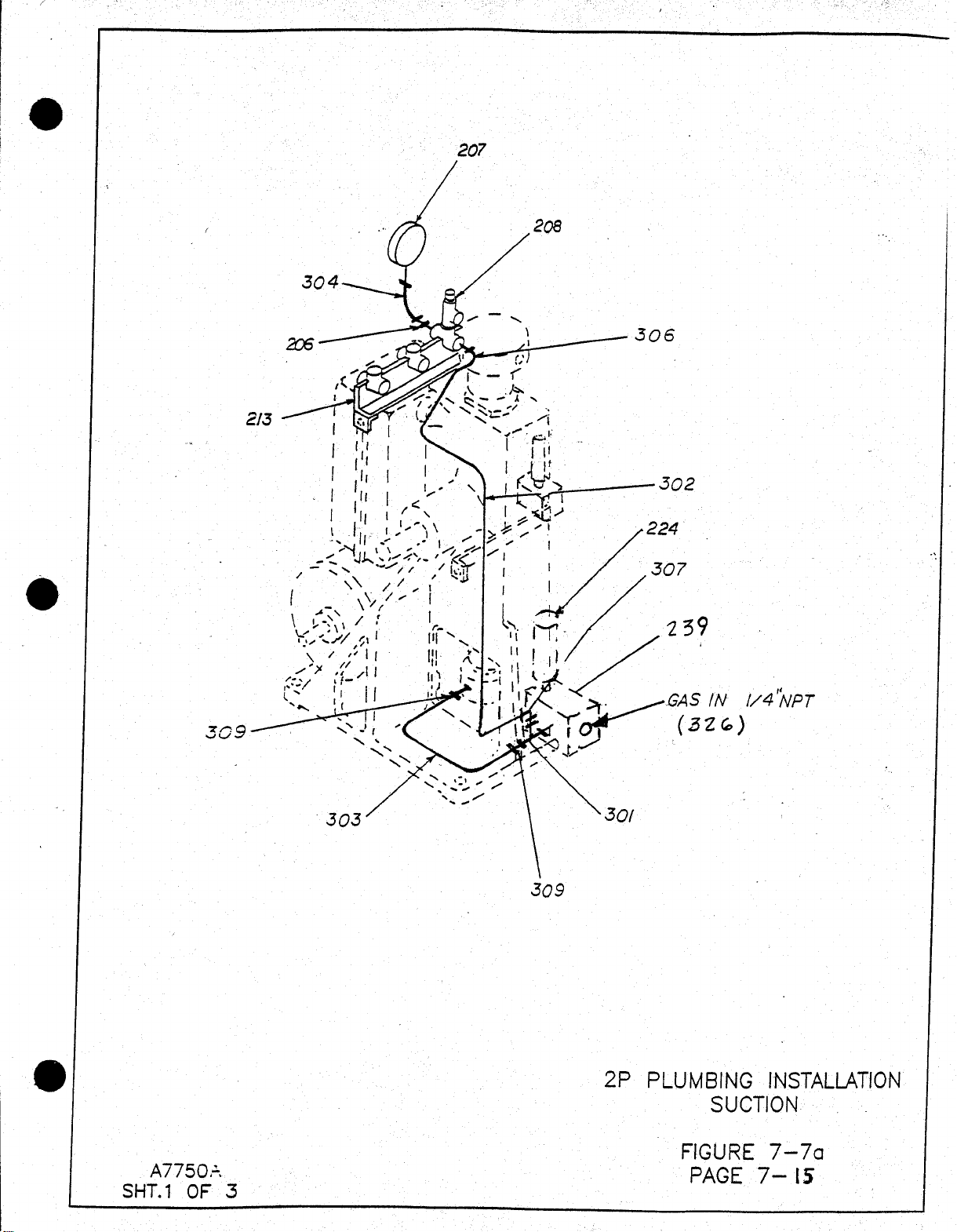
Page 61

Page 62

Page 63

Page 64

Page 65

Page 66

RIX 2PS2B OXYGEN COMPRESSOR
PART NO.
DESCRIPTION
Figure
Index
per unit
Cost ea
COST
XA508-A7783
1
387.85
387.85
Kit price
729.10
Phone 707-747-5900, Fax 707-747-9200
NEW COMPRESSOR SPARES KIT
PART NUMBER 204-6404
QTY COST TOTAL
41-520J6 Belt #7-7 217 1 23.40 23.40
45-1006 O2 Grease (2 oz) 1 32.50 32.50
X123-018-5-90 O-ring, 2nd head #7-2 2 3 3.00 9.00
X123-030-5 O-ring, 1st head #7-1 10 2 3.00 6.00
X123-313-5 O-ring #7-1 26 2 3.75 7.50
X123-904-3 O-ring, head plug #7-8a 312 2 3.00 6.00
X15-B2706 Reed Valve, 2nd stage #7-2 1 2 30.00 60.00
X15-B5840 Reed Valve, Suction 1st #7-4 1 1 30.00 30.00
X15-B5878 Reed Valve, Discharge 1st #7-4 4 1 26.70 26.70
X17-758 Pin #7-2 5 3 3.00 9.00
X18-A2750-5G Rider Ring, 1/2" #7-1 34 1 10.25 10.25
X18-B2117-2G Rider Ring, 1.25" #7-1 27 2 18.60 37.20
X18-C1147-14-1G Rider Ring, 1-3/4" #7-1 5 1 37.20 37.20
X18-C1791-10G Piston Ring,1.25" #7-1 25 2 23.25 46.50
Piston A'ssy, 2nd stage #7-1 36
Note #1: Reference, Technical manual 2PS2B
All pricing in U.S. Dollars, FOB RIX. Prices valid thru 12-02.
$75 minimum. $100 expedite fee. $30 wire transfer fee.
$30 export document fee - waived with credit card payment. $500 Letter of Credit fee.
2PS2B Parts 5-01
Page 67

Discharge
pressure
switch
Check
Valve
Back
pressure
regulator
Gas Inlet
Gas outlet
Inlet
pressure
switch
 Loading...