

Page 1

Getting Started Guide
January 2008
Page 2

© 2003-2007 Riverbed Technology, Incorporated. All rights reserved.
Riverbed Technology, Riverbed, Steelhead, RiOS, Interceptor and the Riverbed logo are trademarks or registered
trademarks of Riverbed Technology, Inc. All other trademarks used or mentioned herein belong to their
respective owners.
Linux is a trademark of Linus Torvalds in the United States and in other countries. JInitiator is a trademark or a
registered trademark of Oracle Corporation. Microsoft, Windows, Windows NT, Windows 2000, Windows Vista,
Outlook, and Internet Explorer are trademarks or registered trademarks of Microsoft Corporation in the United
States and in other countries. UNIX is a registered trademark in the United States and in other countries,
exclusively licensed through X/Open Company, Ltd.
Parts of this product are derived from the following software:
Apache © 2000-2003. The Apache Software Foundation. All rights reserved.
Busybox © 1999-2005 Eric Andersen
ethtool © 1994, 1995-8, 1999, 2001, 2002 Free Software Foundation, Inc.
Less © 1984-2002 Mark Nudelman
Libevent © 2000-2002 Niels Provos. All rights reserved.
LibGD, Version 2.0 licensed by Boutell.Com, Inc.
Libtecla © 2000, 2001 by Martin C. Shepherd. All rights reserved.
Linux Kernel © Linus Torvalds
login 2.11 © 1993 The Regents of the University of California. All rights reserved.
md5, md5.cc © 1995 University of Southern California, © 1991-2, RSA Data Security, Inc.
my_getopt.{c,h} © 1997, 2000, 2001, 2002, Benjamin Sittler. All rights reserved.
NET-SNMP © Copyright 1989, 1991, 1992 by Carnegie Mellon University. All rights reserved. Derivative Work 1996, 1998-2000 Copyright 1996, 1998-2000 The Regents of the University of California. All rights reserved.
OpenSSH, © 1983, 1990, 1992, 1993, 1995, 1993 The Regents of the University of California. All rights reserved.
pam © 2002-2004 Tall Maple Systems, Inc. All rights reserved.
pam-radius © 1989, 1991 Free Software Foundation, Inc.
pam-tacplus © 1997-2001 by Pawel Krawczyk
ssmtp GNU General Public License
syslogd © 2002-2005 Tall Maple Systems, Inc. All rights reserved.
Vixie-Cron © 1988, 1990, 1993, 1994 by Paul Vixie. All rights reserved.
Zile © 1997-2001 Sandro Sigalam © 2003 Reuben Thomas. All rights reserved.
This product includes software developed by the University of California, Berkeley and its contributors. This
product is derived from the RSA Data Security, Inc. MD5 Message-Digest Algorithm.
For detailed copyright and license agreements or modified source code (where required), see the Riverbed
Technical Support site at https://support.riverbed.com.
Other product names, brand names, marks, and symbols are registered trademarks or trademarks of their
respective owners.
The content of this manual is furnished on a RESTRICTED basis and is subject to change without notice and
should not be construed as a commitment by Riverbed Technology, Incorporated. Use, duplication, or disclosure
by the U.S. Government is subject to restrictions set forth in Subparagraphs (c) (1) and (2) of the Commercial
Computer Software Restricted Rights at 48 CFR 52.227-19, as applicable. Riverbed Technology, Incorporated
assumes no responsibility or liability for any errors or inaccuracies that may appear in this book.
Fourth Edition (January 2008)
Riverbed Technology
199 Fremont Street
San Francisco, CA 94105
Phone: 415.247.8800
Fax: 415.247.8801
Web: http://www.riverbed.com
Par t Num ber
710-00102 (PUB-00048)
Page 3

Contents
Preface .............................................................................................................................11
About This Guide ....................................................................................................................................... 11
Types of Users...................................................................................................................................... 11
Organization of This Guide................................................................................................................ 11
Document Conventions...................................................................................................................... 12
Hardware and Software Dependencies................................................................................................... 12
Additional Resources................................................................................................................................. 14
Online Notes......................................................................................................................................... 14
RiOS Documentation .......................................................................................................................... 15
Online Documentation........................................................................................................................ 15
Safety Guidelines ........................................................................................................................................ 15
Contacting Riverbed................................................................................................................................... 15
Internet.................................................................................................................................................. 15
Technical Support................................................................................................................................ 15
Documentation..................................................................................................................................... 15
Chapter 1 Installing the Steelhead Appliance ...................................................................................17
Installing the Steelhead Appliance........................................................................................................... 17
1. Getting Started................................................................................................................................. 17
2. Installing on a Rack ......................................................................................................................... 18
3. Connecting the Power..................................................................................................................... 18
4. Connecting to the Steelhead Appliance ....................................................................................... 18
5. Connecting the Steelhead Appliance to Your Network............................................................. 19
6. Checking Your Connections........................................................................................................... 20
7. Connecting to the Management Console..................................................................................... 20
Guía rápida de instalación del Dispositivo Steelhead........................................................................... 20
1. Introducción ..................................................................................................................................... 21
2. Instalación en un bastidor.............................................................................................................. 21
3. Conexión de la fuente de alimentación........................................................................................ 21
4. Conexión con el Dispositivo Steelhead ........................................................................................ 22
5. Conexión del Dispositivo Steelhead con la red........................................................................... 22
6. Comprobación de las conexiones.................................................................................................. 23
7. Conexión con la consola de administración................................................................................ 24
Schnellinstallation des Steelhead-Geräts................................................................................................. 24
1. Erste Schritte..................................................................................................................................... 24
2. Montage in einem Rack .................................................................................................................. 24
3. Stromanschluss ................................................................................................................................ 25
4. Verbinden des Steelhead-Geräts.................................................................................................... 25
5. Verbinden des Steelhead-Geräts mit dem Netzwerk ................................................................. 26
GETTING STARTED GUIDE III
Page 4

6. Überprüfen der Verbindungen ...................................................................................................... 27
7. Verbinden der Verwaltungskonsole.............................................................................................. 27
Guide d'installation rapide de l'appareil Steelhead............................................................................... 27
1. Mise en route.................................................................................................................................... 27
2. Montage sur un support................................................................................................................. 28
3. Branchement sur secteur ................................................................................................................ 28
4. Branchement à l'appareil Steelhead.............................................................................................. 28
5. Connexion de l'appareil Steelhead à votre réseau...................................................................... 29
6. Vérification des branchements ...................................................................................................... 30
7. Connexion à la Console de gestion............................................................................................... 30
Installazione dell'Apparecchiatura Steelhead ........................................................................................ 30
1. Operazioni preliminari ................................................................................................................... 30
2. Installazione nel rack ...................................................................................................................... 31
3. Collegamento dell'alimentazione.................................................................................................. 31
4. Collegamento dell'Apparecchiatura Steelhead........................................................................... 32
5. Collegamento dell'Apparecchiatura Steelhead alla rete............................................................ 32
6. Verifica della connessione .............................................................................................................. 33
7. Accesso alla console di gestione.................................................................................................... 33
Steelhead Appliance.......................................................................................................................... 34
安装
1.
使用入门
2.
在机架上安装
连接电源
3.
4.
连接到
5.
将
Steelhead
检查连接
6.
7.
连接到管理控制台
설치
Steelhead Appliance.......................................................................................................................... 37
시작하기
1.
랙에 설치
2.
3.
전원 연결
4.
Steelhead
5.
네트워크에
6.
관리 콘솔에 연결
7.
소프트웨어 및 설명서 업데이트
............................................................................................................................. 34
...................................................................................................................... 34
............................................................................................................................. 34
Steelhead
信息家电
............................................................................................... 35
信息家电连接到网络
..................................................................................... 35
............................................................................................................................ 36
............................................................................................................... 37
............................................................................................................................. 37
............................................................................................................................ 37
............................................................................................................................ 38
어플라이언스에 연결
Steelhead
어플라이언스 연결
......................................................................................... 38
.......................................................................... 39
................................................................................................................ 40
......................................................................................... 40
Руководство по быстрой установке устройств Steelhead ........................................................ 41
1. Начало работы ................................................................................................................. 41
2. Установк а в стойку ........................................................................................................... 41
3. Подключение электропитания......................................................................................... 41
4. Подключение к устройству Steelhead ............................................................................. 42
5. Подключение устройства ЦКА к вашей сети .................................................................. 42
6. Проверка сделанных соединений ................................................................................... 43
7. Подключение к консоли администрирования ................................................................ 44
Chapter 2 Installing and Deploying Steelhead Mobile .....................................................................45
Installing and Deploying Steelhead Mobile............................................................................................ 45
Overview .............................................................................................................................................. 45
1. Getting Started................................................................................................................................. 46
IV CONTENTS
Page 5

2. Deploying Steelhead Mobile in Environments with Firewalls................................................. 48
3. Installing on a Rack ......................................................................................................................... 48
4. Connecting the Power..................................................................................................................... 48
5. Connecting to the Mobile Controller............................................................................................ 49
6. Configuring the Mobile Controller............................................................................................... 49
7. Connecting the Mobile Controller to Your Network.................................................................. 49
8. Logging into the Mobile Controller.............................................................................................. 49
9. Next Steps......................................................................................................................................... 50
Instalación y despliegue de Steelhead Mobile........................................................................................ 50
Descripción general............................................................................................................................. 50
1. Introducción ..................................................................................................................................... 51
2. Despliegue de Steelhead Mobile en entornos con servidores de seguridad........................... 53
3. Instalación en un bastidor.............................................................................................................. 53
4. Conexión de la fuente de alimentación........................................................................................ 53
5. Conexión con el Mobile Controller............................................................................................... 54
6. Configuración de Mobile Controller............................................................................................. 54
7. Conexión de Mobile Controller a la red....................................................................................... 54
8. Inicio de sesión en el Mobile Controller....................................................................................... 55
9. Pasos siguientes ............................................................................................................................... 55
Installation und Bereitstellung von Steelhead Mobile .......................................................................... 55
Übersicht............................................................................................................................................... 55
1. Erste Schritte..................................................................................................................................... 56
2. Bereitstellung von Steelhead Mobile in Umgebungen mit Firewalls ...................................... 58
3. Montage in einem Rack .................................................................................................................. 58
4. Stromanschluss ................................................................................................................................ 58
5. Verbinden mit Mobile Controller .................................................................................................. 59
6. Konfigurieren des Mobile Controllers.......................................................................................... 59
7. Verbinden des Mobile Controllers mit dem Netzwerk.............................................................. 59
8. Anmelden am Mobile Controller.................................................................................................. 60
9. Nächste Schritte ............................................................................................................................... 60
Installation et déploiement de Steelhead Mobile................................................................................... 60
Généralités............................................................................................................................................ 60
1. Mise en route.................................................................................................................................... 61
2. Déploiement de Steelhead Mobile dans des environnements protégés par des pare-feu.... 63
3. Montage sur un support................................................................................................................. 63
4. Branchement sur secteur ................................................................................................................ 63
5. Connexion au Mobile Controller................................................................................................... 64
6. Configuration du Mobile Controller............................................................................................. 64
7. Connexion du Mobile Controller à votre réseau......................................................................... 64
8. Connexion au Mobile Controller................................................................................................... 65
9. Étapes suivantes............................................................................................................................... 65
Installazione e distribuzione di Steelhead Mobile................................................................................. 65
Panoramica........................................................................................................................................... 65
1. Operazioni preliminari ................................................................................................................... 66
2. Distribuzione di Steelhead Mobile in ambienti con firewall..................................................... 68
3. Installazione nel rack ...................................................................................................................... 68
4. Collegamento dell'alimentazione.................................................................................................. 68
5. Connessione al Mobile Controller................................................................................................. 69
GETTING STARTED GUIDE V
Page 6

6. Configurazione del Mobile Controller ......................................................................................... 69
7. Collegamento del Mobile Controller alla rete............................................................................. 69
8. Accesso al Mobile Controller......................................................................................................... 70
9. Passaggi successivi.......................................................................................................................... 70
安装和部署
概述
1.
2.
3.
4.
5.
6.
7.
8.
9.
Steelhead Mobile
........................................................................................................................................ 70
使用入门
............................................................................................................................. 71
在含防火墙的环境中部署
在机架上安装
连接电源
连接到
配置
将
Mobile Controller
登录到
后继步骤
............................................................................................................................. 73
Mobile Controller .................................................................................................... 73
Mobile Controller ........................................................................................................ 74
Mobile Controller .................................................................................................... 74
............................................................................................................................. 75
Steelhead Mobile
개요
........................................................................................................................................ 75
1.
시작하기
방화벽이 있는 환경에
2.
3.
랙에 설치
전원 연결
4.
............................................................................................................................. 76
............................................................................................................................ 77
............................................................................................................................ 78
5. Mobile Controller
6. Mobile Controller
네트워크에
7.
8. Mobile Controller
9.
다음 단계
............................................................................................................................ 79
................................................................................................................... 70
Steelhead Mobile ....................................................................... 73
...................................................................................................................... 73
连接到网络
설치 및 배포
................................................................................................................. 75
Steelhead Mobile
에 연결
구성
................................................................................................... 78
........................................................................................................ 78
Mobile Controller
에 로그인
........................................................................................ 74
배포
.................................................................... 77
연결
..................................................................................... 79
................................................................................................ 79
Уста н о в к а и ввод в действие устройства Steelhead Mobile ..................................................... 80
Обзор..................................................................................................................................... 80
1. Начало работы ................................................................................................................. 80
2. Размещение Steelhead Mobile в средах со шлюзами безопасности ............................ 82
3. Установк а в стойку ........................................................................................................... 82
4. Подключение электропитания......................................................................................... 84
5. Подключение к Mobile Controller...................................................................................... 84
6. Конфигурирование Mobile Controller ............................................................................... 84
7. Подключение устройства Mobile Controller к сети.......................................................... 85
8. Регистрация в журнале устройства Mobile Controller .................................................... 85
9. Последующие действия................................................................................................... 85
Chapter 3 Installing the Central Management Console ...................................................................87
Installing the CMC...................................................................................................................................... 87
1. Getting Started................................................................................................................................. 87
2. Installing on a Rack ......................................................................................................................... 87
3. Connecting the Power..................................................................................................................... 88
4. Connecting to the CMC .................................................................................................................. 88
5. Configuring the CMC ..................................................................................................................... 88
6. Connecting the CMC to Your Network........................................................................................ 88
7. Checking Your Connections........................................................................................................... 89
8. Logging into the CMC .................................................................................................................... 89
VI CONTENTS
Page 7

9. Creating Appliance Profiles........................................................................................................... 89
10. Creating Appliance Groups......................................................................................................... 89
11. Registering Steelhead Appliances............................................................................................... 90
Guía rápida de instalación de la consola CMC ...................................................................................... 90
1. Introducción ..................................................................................................................................... 90
2. Instalación en un bastidor.............................................................................................................. 90
3. Conexión de la fuente de alimentación........................................................................................ 90
4. Conexión con el Dispositivo CMC................................................................................................ 91
5. Configuración del Dispositivo CMC ............................................................................................ 91
6. Conexión del Dispositivo CMC con la red .................................................................................. 92
7. Comprobación de las conexiones.................................................................................................. 92
8. Conexión con el Dispositivo CMC................................................................................................ 92
9. Creación de perfiles de Dispositivo.............................................................................................. 92
10. Creación de grupos de Dispositivos........................................................................................... 93
11. Registro de Dispositivos Steelhead............................................................................................. 93
Schnellinstallation der CMC ..................................................................................................................... 93
1. Erste Schritte..................................................................................................................................... 93
2. Montage in einem Rack .................................................................................................................. 93
3. Stromanschluss ................................................................................................................................ 94
4. Verbinden des CMC-Geräts ........................................................................................................... 94
5. Konfigurieren des CMC-Geräts..................................................................................................... 94
6. Verbinden des CMC-Geräts mit dem Netzwerk......................................................................... 95
7. Überprüfen der Verbindungen ...................................................................................................... 95
8. Verbinden mit der CMC ................................................................................................................. 95
9. Erstellen von Geräteprofilen.......................................................................................................... 95
10. Erstellen von Gerätegruppen....................................................................................................... 95
11. Registrieren der Steelhead-Geräte............................................................................................... 96
Guide d'Installation rapide de la CMC.................................................................................................... 96
1. Mise en route.................................................................................................................................... 96
2. Montage sur un support................................................................................................................. 96
3. Branchement sur secteur ................................................................................................................ 96
4. Branchement à l'appareil CMC...................................................................................................... 97
5. Configuration de l'appareil CMC.................................................................................................. 97
6. Connexion de l'appareil CMC à votre réseau.............................................................................. 98
7. Vérification des branchements ...................................................................................................... 98
8. Connexion à la Console CMC........................................................................................................ 98
9. Création de profils d'appareil........................................................................................................ 98
10. Création de profils d'appareil ...................................................................................................... 98
11. Enregistrements d'appareils Steelhead....................................................................................... 99
Installazione della Central Management Console (CMC).................................................................... 99
1. Operazioni preliminari ................................................................................................................... 99
2. Installazione nel rack ...................................................................................................................... 99
3. Collegamento dell'alimentazione.................................................................................................. 99
4. Accesso alla console CMC............................................................................................................ 100
5. Configurazione della console CMC............................................................................................ 100
6. Collegamento della console CMC alla rete................................................................................ 100
7. Verifica della connessione ............................................................................................................ 101
8. Accesso alla console CMC............................................................................................................ 101
GETTING STARTED GUIDE VII
Page 8

9. Creazione di profili di Apparecchiature..................................................................................... 101
10. Creazione di gruppi di Apparecchiature ................................................................................. 101
11. Registrazione dell'Steelhead Apparecchiature........................................................................ 102
CMC................................................................................................................................................... 102
安装
. 使用入门
1
2.
在机架上安装
3.
连接电源
4.
连接到
5.
配置
6.
连接
7.
检查连接
8.
登录到
9.
创建信息家电配置文件
10.
创建信息家电组
11.
注册
Central Management Console (
1.
시작하기
2. 랙에 설치
3.
전원 연결
4.
CMC에
5.
CMC
6.
네트워크에 CMC 연결
7.
연결 확인
8. CMC
9.
어플라이언스 프로필 만들기
10.
어플라이언스 그룹 만들기
11. Steelhead Appliance 등록
......................................................................................................................... 102
.................................................................................................................... 102
........................................................................................................................... 102
CMC...................................................................................................................... 103
CMC ......................................................................................................................... 103
CMC
到网络
............................................................................................................. 103
........................................................................................................................... 104
CMC ................................................................................................................................... 104
...................................................................................................... 104
............................................................................................................... 104
Steelhead Appliance........................................................................................................... 105
CMC)설치
.......................................................................................... 105
........................................................................................................................... 105
.......................................................................................................................... 105
.......................................................................................................................... 105
연결
.................................................................................................................... 106
구성
......................................................................................................................... 106
...................................................................................................... 106
.......................................................................................................................... 107
에 로그인
................................................................................................................. 107
............................................................................................ 107
.............................................................................................. 107
.............................................................................................. 108
Руководство по быстрой установке CMC............................................................................... 108
1. Начало работы ............................................................................................................... 108
2. Установк а в стойку ......................................................................................................... 108
3. Подключение электропитания....................................................................................... 108
4. Конфигурирование устройства CMC ............................................................................ 109
5. одключение устройства CMC к вашей сети.................................................................. 109
6. Подключение устройства CMC к вашей сети ............................................................... 110
7. Проверка сделанных соединений ................................................................................. 110
8. Подключение к CMC....................................................................................................... 110
9. Создание профилей устройства ................................................................................... 110
10. Создание групп устройств ........................................................................................... 111
11. Регистр ация устройств Steelhead................................................................................ 111
Chapter 4 Installing the Interceptor Appliance ...............................................................................113
Installing the Interceptor Appliance...................................................................................................... 113
Overview ............................................................................................................................................ 113
1. Getting Started............................................................................................................................... 114
2. Installing on a Rack ....................................................................................................................... 114
3. Powering On the Interceptor Appliance.................................................................................... 114
4. Connecting to the Interceptor Appliance................................................................................... 114
5. Configuring the Interceptor Appliance...................................................................................... 115
VIII CONTENTS
Page 9

6. Connecting the Interceptor Appliance to Your Network ........................................................ 116
7. Verifying Your Connections......................................................................................................... 117
8. Configuring Routing..................................................................................................................... 117
Instalación del Dispositivo Interceptor.................................................................................................. 117
Descripción general........................................................................................................................... 117
1. Introducción ................................................................................................................................... 118
2. Instalación en un bastidor............................................................................................................ 118
3. Encendido del Dispositivo Interceptor....................................................................................... 118
4. Conexión con el Dispositivo Interceptor.................................................................................... 119
5. Configuración del Dispositivo Interceptor................................................................................ 119
6. Conexión del Dispositivo Interceptor a su red.......................................................................... 120
7. Comprobación de las conexiones................................................................................................ 121
8. Configuración del enrutamiento................................................................................................. 121
Installieren von Interceptor-Gerät.......................................................................................................... 121
Übersicht............................................................................................................................................. 122
1. Erste Schritte................................................................................................................................... 122
2. Montage in einem Rack ................................................................................................................ 122
3. Einschalten von Interceptor-Gerät.............................................................................................. 122
4. Verbinden mit Interceptor-Gerät................................................................................................. 123
5. Konfigurieren des Interceptor-Geräts......................................................................................... 123
6. Verbinden von Interceptor-Gerät mit dem Netzwerk.............................................................. 124
7. Überprüfen der Verbindungen .................................................................................................... 125
8. Konfigurieren des Routings......................................................................................................... 125
Installation de l’Appareil Interceptor .................................................................................................... 125
Généralités.......................................................................................................................................... 126
1. Mise en route.................................................................................................................................. 126
2. Montage sur un support............................................................................................................... 126
3. Mise sous tension de l’Appareil Interceptor.............................................................................. 126
4. Connexion à l’Appareil Interceptor ............................................................................................ 127
5. Configuration de l’Appareil Interceptor.................................................................................... 127
6. Connexion de l’Appareil Interceptor à votre réseau................................................................ 128
7. Vérification de vos connexions.................................................................................................... 129
8. Configuration du routage............................................................................................................. 129
Installazione dell'Apparecchiatura Interceptor.................................................................................... 129
Panoramica......................................................................................................................................... 130
1. Operazioni preliminari ................................................................................................................. 130
2. Installazione nel rack .................................................................................................................... 130
3. Accensione dell'Apparecchiatura Interceptor ........................................................................... 130
4. Connessione all'Apparecchiatura Interceptor ........................................................................... 131
5. Configurazione dell'Apparecchiatura Interceptor.................................................................... 131
6. Collegamento dell'Apparecchiatura Interceptor alla rete........................................................ 132
7. Verifica delle connessioni ............................................................................................................. 133
8. Configurazione dell'indirizzamento........................................................................................... 133
安装
Interceptor
概述
...................................................................................................................................... 134
1.
使用入门
2.
在机架上安装
打开 Interceptor Appliance
3.
信息家电
........................................................................................................................ 133
........................................................................................................................... 134
.................................................................................................................... 134
....................................................................................................... 134
GETTING STARTED GUIDE IX
Page 10

4.
连接到
5.
配置 Interceptor Appliance
6.
连接 Interceptor Appliance 到网络
7.
验证连接
8.
配置路由
설치
Interceptor
개요
1.
시작하기
랙에 설치
2.
3. Interceptor Appliance
4. Interceptor Appliance
5. Interceptor
6.
네트워크에
7.
연결 확인
8.
라우팅 구성
Interceptor Appliance
........................................................................................... 135
....................................................................................................... 135
................................................................................ 136
........................................................................................................................... 137
........................................................................................................................... 137
어플라이언스
................................................................................................................ 137
...................................................................................................................................... 138
........................................................................................................................... 138
.......................................................................................................................... 138
에 전원 공급
에 연결
어플라이언스 구성
Interceptor Appliance
.................................................................................. 138
.......................................................................................... 139
.......................................................................................... 139
연결
........................................................................... 140
.......................................................................................................................... 141
....................................................................................................................... 141
Уста н о в к а Устройства Interceptor............................................................................................. 141
Обзор................................................................................................................................... 142
1. Начало работы ............................................................................................................... 142
2. Установк а в стойку ......................................................................................................... 142
3. Включение Interceptor Appliance.................................................................................... 142
4. Подключение к Interceptor Appliance ............................................................................. 143
5. Конфигурирование устройства Interceptor ................................................................... 143
6. Подключение устройства Interceptor к сети.................................................................. 144
7. Проверка соединений .................................................................................................... 145
8. Конфигурирование маршрутизации.............................................................................. 145
X CONTENTS
Page 11

Preface
Welcome to the Getting Started Guide. Read this introduction for an overview of the information provided
in this guide and for an understanding of the documentation conventions used throughout. This
introduction contains the following sections:
“About This Guide,” next
“Hardware and Software Dependencies” on page 12
“Additional Resources” on page 14
“Safety Guidelines” on page 15
“Contacting Riverbed” on page 15
About This Guide
The Getting Started Guide describes how to quickly install and configure your RiOS system.
This guide is intended to provide you with the basic steps for installing and configuring your system. For
detailed information about installing and configuring your RiOS system, consult the appropriate guide:
Steelhead Appliance Installation and Configuration Guide
Steelhead Mobile Controller User’s Guide
Steelhead Central Management Console User’s Guide
Interceptor Appliance User’s Guide
Types of Users
This guide is written for storage and network administrators with familiarity administering and managing
WANS using common network protocols such as TCP, CIFS, HTTP, FTP, NFS, and so forth.
Organization of This Guide
The Getting Started Guide includes the following sections:
GETTING STARTED GUIDE 11
Page 12

Chapter 1, “Installing the Steelhead Appliance,” provides the basic steps for installing and configuring
the Steelhead appliance in English and other languages.
Chapter 2, “Installing and Deploying Steelhead Mobile,” provides the basic steps for installing,
configuring, and deploying Steelhead Mobile.
Chapter 3, “Installing the Central Management Console,” provides the basic steps for installing and
configuring the CMC in English and other languages.
Chapter 4, “Installing the Interceptor Appliance,” provides the basic steps for installing and
configuring the Interceptor appliance in English and other languages.
Document Conventions
This manual uses the following standard set of typographical conventions to introduce new terms, illustrate
screen displays, describe command syntax, and so forth.
Convention Meaning
italics Within text, new terms and emphasized words appear in italic typeface.
boldface Within text, commands, keywords, identifiers (names of classes, objects, constants, events,
functions, program variables), environment variables, filenames, Graphical User Interface
(GUI) controls, and other similar terms appear in bold typeface.
Courier Information displayed on your terminal screen and information that you are instructed to
enter appears in Courier font.
< > Within syntax descriptions, values that you specify appear in angle brackets. For example:
interface <ipaddress>
[] Within syntax descriptions, optional keywords or variables appear in brackets. For example:
ntp peer <addr> [version <number>]
{} Within syntax descriptions, required keywords or variables appear in braces. For example:
{delete <filename> | upload <filename>}
| Within syntax descriptions, the pipe symbol represents a choice to select one keyword or
variable to the left or right of the symbol. (The keyword or variable can be either optional or
required.) For example:
{delete <filename> | upload <filename>}
Hardware and Software Dependencies
The following table summarizes the hardware and software requirements for the RiOS systems.
Steelhead Appliance Hardware and Software Requirements
Steelhead Appliance
19 inch (483 mm) two or four-post rack. (The Model 50, 100, 200, 300 does not
require a rack.)
Steelhead Management Console Any computer that supports a Web browser with a color image display.
The Management Console has been tested with Mozilla Firefox version
1.0.xand 1.5.x and Microsoft Internet Explorer version 6.0x.
NOTE: Javascript and cookies must be enabled in your Web browser.
12 PREFACE
Page 13

Steelhead Mobile Hardware, Software, and Configuration Requirements
Mobile Controller 19-inch (483 mm) two- or four-post rack.
Mobile Controller Console Any computer that supports a Web browser with a color image display.
The Mobile Controller console has been tested with Mozilla Firefox version
1.0.x, 1.5.x and 2.0, and Microsoft Internet Explorer version 6.x and 7.0.
NOTE: Javascript and cookies must be enabled in your Web browser.
NOTE: If you want to encrypt your communication, you must have an SSL
capable browser.
No particular operating system is required.
Mobile Client Pentium III, 1.5 Mhz, 512 MB of RAM.
At least 1 GB of disk space for the data store.
Minimum Windows 2000 Professional SP4, Windows XP SP2 or Windows
Vista.
The client firewall must allow port 7801.
If you are enforcing outbound security, you must allow the following client
application components; rbtdebug.exe, rbtmon.exe, shmobile.exe, and
rbtsport.exe.
Administrator privileges are required to install Mobile Client software. User
privileges are required to run the software.
No more than one Mobile Client software installation. Multiple installations of
the Mobile Client software on a single endpoint is not supported. Fast user
switching is also not supported.
VPN environments require that the VPN tunnel not be optimized. When you
configure the acceleration policy, add a pass-through rule for the endpoint
client VPN port number.
Steelhead Appliance Version 4.0.x.
CMC Hardware Requirements Software and Operating System Requirements
Any computer that supports a Web browser with
color image display.
GETTING STARTED GUIDE 13
The CMC has been tested with Mozilla Firefox 1.0.x and
1.5.x, and Microsoft Internet Explorer 6.0x.
Note: Javascript and cookies must be enabled in your
browser.
Note: If you want to encrypt your communication, you must
have a Secure Sockets Layer (SSL) capable browser.
No particular operating system is required.
Page 14

Interceptor Hardware Requirements Software Requirements
Any computer that supports a Web browser with a
color image display.
RiOS CLI Hardware Requirements
One of the following:
• An ASCII terminal or emulator that can connect to
the serial console (9600 baud, 8 bits, no parity, 1
stop bit, and no flow control).
• A computer with a Secure Shell (ssh) client that is
connected by an IP network to the appliance
Primary interface.
Additional Resources
• Firefox 1.2.1
• Microsoft Internet Explorer 6.0x
Note: Javascript and cookies must be enabled in your
browser.
Note: If you want to encrypt your communication, you must
have an SSL-capable browser.
Software Requirements
Operating System Requirements
• Secure Shell (ssh). Free ssh clients include PuTTY for
Windows computers, OpenSSH for many Unix and Unixlike operating systems, and Cygwin.
This section describes resources that supplement the information in this guide. It contains the following
sections:
“Online Notes,” next
“RiOS Documentation” on page 15
“Online Documentation” on page 15
“Safety Guidelines” on page 15
Online Notes
The following online file supplements the information in this guide. It is available on the Riverbed Technical
Support site at http://www.riverbed.com.
Online File Purpose
<product>_<version_number>.txt Describes the product release and identifies fixed problems, known
problems, and workarounds. This file also provides documentation
information not covered in the manuals or that has been modified since
publication.
Please examine the release notes for your system before you begin the installation and configuration
process. It contains important information about the most recent release of RiOS systems.
14 PREFACE
Page 15

RiOS Documentation
You can access the complete document set for the RiOS systems on the Documentation Set CD that
accompanied your system.
Online Documentation
The Steelhead appliance documentation set is periodically updated with new information. To access the
most current version of the Steelhead appliance documentation and other technical information, consult the
Riverbed Technical Support site located at http://www.riverbed.com.
Safety Guidelines
Follow the safety precautions outlined in the Safety and Compliance Guide when installing and setting up
your system.
IMPORTANT: Failure to follow these safety guidelines can result in injury or damage to the equipment. Mishandling
of the equipment voids all warranties. Please read and follow safety guidelines and installation instructions carefully.
The Safety and Compliance Guide contains the safety information in English and other languages. Before you
install, operate, or service your system, you must be familiar with the safety information. Refer toSafety and
Compliance Guide if you do not clearly understand the safety information provided in the documentation.
Contacting Riverbed
This section describes how to contact departments within Riverbed.
Internet
You can find out about Riverbed products through our Web site at http://www.riverbed.com.
Technical Support
If you need technical support, for the fastest service, please open a trouble ticket at
https://support.riverbed.com. You can also call 1-87-RIVERBED (1-877-483-7233) in the United States and
Canada or +1 (415) 247-7381 outside the United States.
Documentation
We continually strive to improve the quality and usability of our documentation. We appreciate any
suggestions you may have about our online documentation or printed materials. Send documentation
comments to [email protected].
GETTING STARTED GUIDE 15
Page 16

16 PREFACE
Page 17

CHAPTER 1 Installing the Steelhead Appliance
In This Chapter
This chapter describes how to quickly install and configure the Steelhead appliance in English and other
languages. For detailed information about installing and configuring the Steelhead appliance, see the
Steelhead Appliance Installation and Configuration Guide.
1 INSTALLING THE STEELHEAD APPLI ANCE
Installing the Steelhead Appliance
This section describes how to quickly install and configure the Steelhead appliance in an in-path
configuration. In an in-path configuration, the Steelhead appliance is in the direct path of the client and
server. For details about additional configuration options, see the Steelhead Appliance Installation and
Configuration Guide.
1. Getting Started
Read the release notes for the product at http://www.riverbed.com/support. They contain important
information about this release.
Check your packing slip to make sure that you have all the necessary parts.
Make sure you have adequate space on a two or four post 19-inch rack. (The Model 50/100/200/300
does not have to be installed on a rack.)
Make sure that the ambient temperature does not exceed 35º C (95º F).
Make sure you have a standard Phillips screwdriver to install the appliance to a rack.
Gather the necessary information:
Host and domain name, IP address, DNS server, default gateway
Primary interface speed and duplex settings
In-path interface IP address, netmask, and default gateway
In-path LAN and WAN interface speed and duplex settings
GETTING STARTED GUIDE 17
Page 18
2. Installing on a Rack
If your model has a bezel, please remove it.
If your model requires rails, attach the rails to each side of the appliance. For details, see the
Documentation Set CD.
Align the screw holes on the flanges with the screw holes on the rack.
Insert and tighten the screws on each side of the appliance.
NOTE: Do not cover the air vents on the top of the Model 50/100/200/300. Doing so will cause restricted air flow and
may damage unit or reduce performance. The Model 50/100/200/300 is a desktop model; it does not need to be
mounted to a rack.
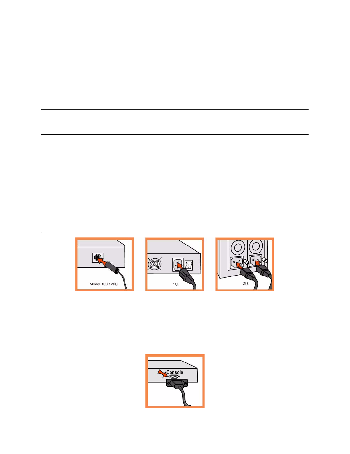
3. Connecting the Power
If your model has a master power switch, make sure it is in the off position (on the rear panel).
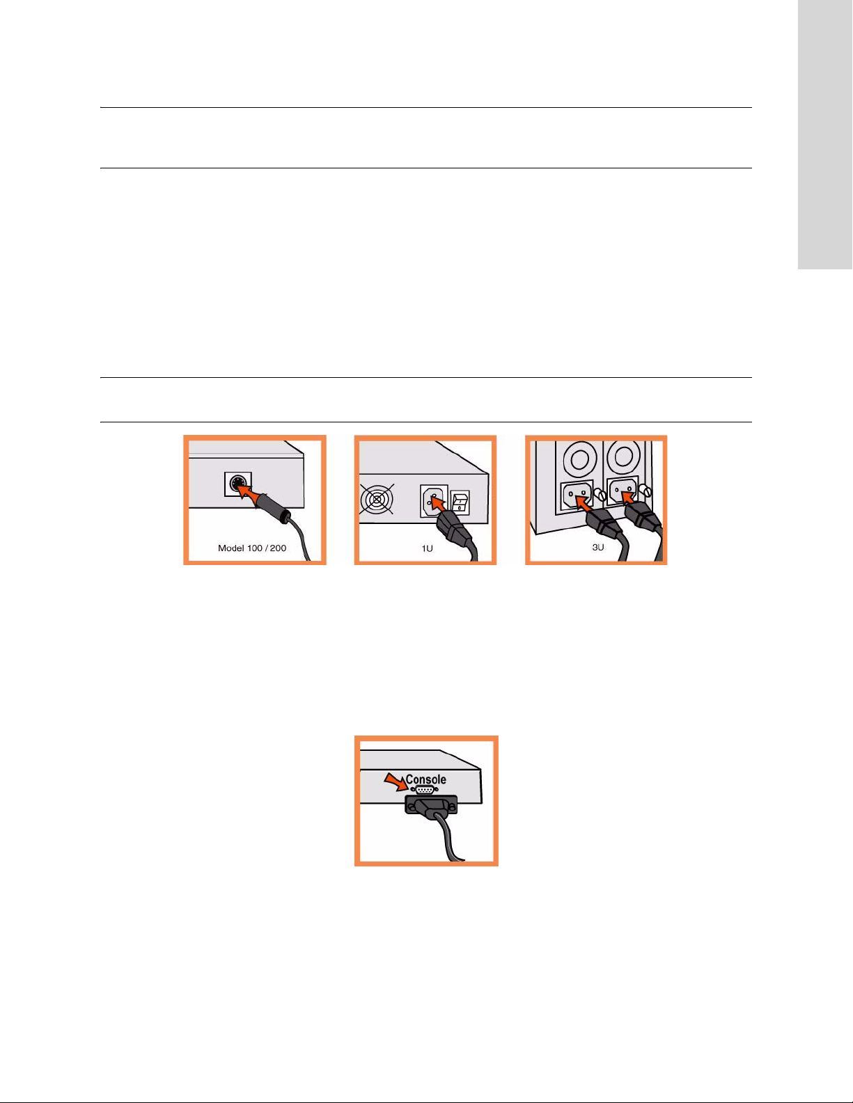
Plug the power cord or cords into the appliance and an AC outlet.
If your model has a master power switch, press in the master power switch (ON).
Press in the system power switch on the front of the appliance.
CAUTION: In all European electrical environments, you must ground the Green/Yellow tab on the power cord. If you
do not ground the Green/Yellow tab, it can cause electrical shock.
4. Connecting to the Steelhead Appliance
Plug the serial cable into the Console port and a terminal.
Make sure the Console port settings are: 9600, 8 data bits, no parity, 1 stop bit, no flow control.
Start your terminal emulation program (for example, HyperTerminal or Tera Term Pro).
At the login prompt, type admin. The default password is password.
18 1 - INSTALLING THE STEELHEAD APPLIANCE
Page 19
The configuration wizard automatically starts when you log into the Steelhead command-line interface
for the first time.
Follow the prompts to configure network and in-path interface settings for the Steelhead appliance.
Confirm your settings; then type exit to log out of the system.
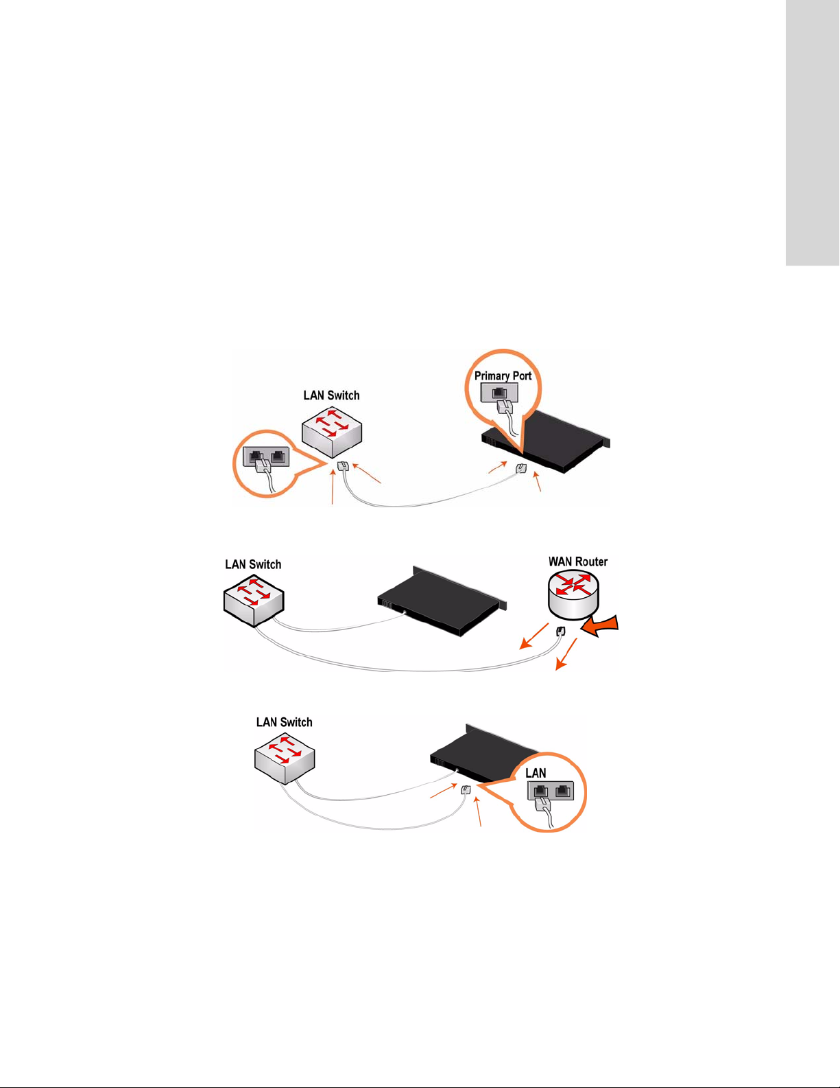
5. Connecting the Steelhead Appliance to Your Network
Make sure you use the correct cables to connect to your network:
– Straight-through cables: Primary and LAN ports to LAN switch.
– Cross-over cable: WAN port to WAN router.
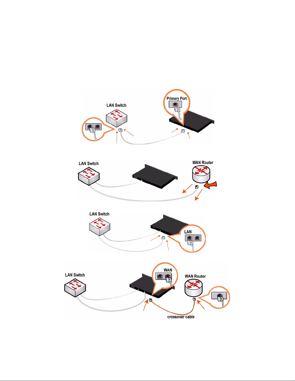
Plug the straight-through cable into the Primary port of the Steelhead appliance and the LAN switch.
This can be any port on your LAN switch that is configured to connect to a host.
1 INSTALLING THE STEELHEAD APPLIANCE
Identify the straight-through cable that connects your LAN switch to your WAN router; unplug the
end connected to the WAN router.
Plug the straight-through cable that you disconnected from the WAN router into the LAN port of the
Steelhead appliance.
GETTING STARTED GUIDE 19
Page 20
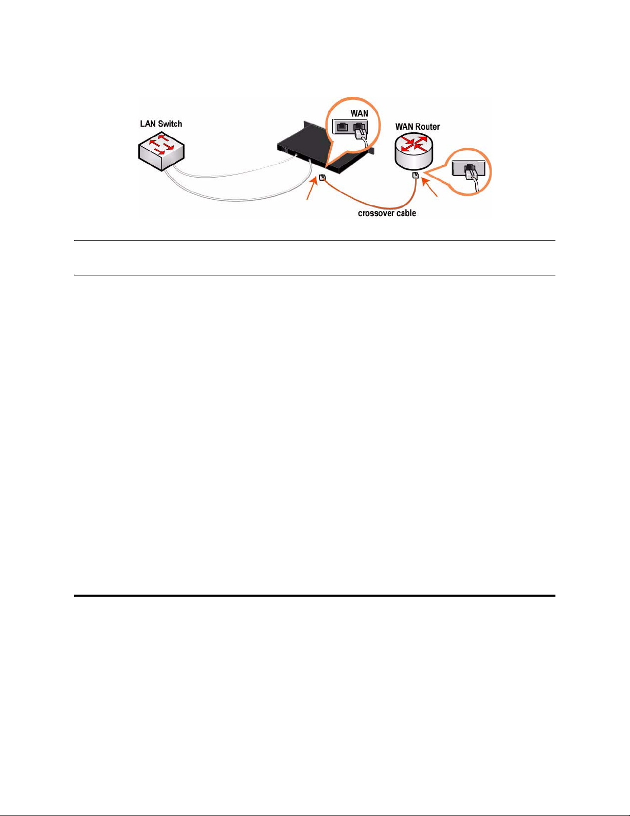
Using the provided cross-over cable, plug the cable into the WAN port of the Steelhead appliance and
the WAN router.
NOTE: If you have a Four-Port Copper Gigabit-Ethernet Bypass card, repeat the installation steps. For detailed
information about installing additional bypass cards, see the Bypass Card Installation Guide.
You can now optimize WAN traffic using the Steelhead appliance.
6. Checking Your Connections
Check the LED status lights to verify that the appliance is connected properly.
To check your connections, enter a ping command from the management interface:
ping -I <primary-IP-address> <primary-default-gateway>
ping -I <in-path-IP-address> <in-path-default-gateway>
7. Connecting to the Management Console
Enter the URL for the Management Console in the location box of your Web browser:
http://host.domain or https://host.domain
The Management Console appears, displaying the Welcome page.
In the Account text box, type admin.
In the Password text box, type the password you assigned.
Click Login to display the Home page.
Guía rápida de instalación del Dispositivo Steelhead
Esto capitulo describe cómo instalar y configurar rápidamente el dispositivo Steelhead en una
configuración “en ruta”. En este tipo de configuración el dispositivo Steelhead se encuentra en la ruta
directa entre el cliente y el servidor. Para obtener información sobre otras opciones de configuración,
consulte el CD de documentación de Riverbed.
20 1 - INSTALLING THE STEELHEAD APPLIANCE
Page 21

1. Introducción
Lea las notas de la versión correspondientes al producto en http://www.riverbed.com/support. Allí
encontrará información importante.
Compruebe con la lista de empaque si cuenta con todas las piezas necesarias.
Asegúrese de contar con el espacio necesario en un bastidor de dos o cuatro postes de 48,26 cm (19
pulgadas).
El Model 50/100/200/300 no se instala en un bastidor.
Asegúrese de que la temperatura ambiente no supere los 35º C (95º F).
Tenga a mano un destornillador Phillips estándar para instalar el dispositivo en el bastidor. En caso de
falla debe ser reparado exclusivamente por personal téchnico calificado designado por la empresa
importadora y/o responsable legal.
Reúna la siguiente información:
Nombre del host y del dominio, dirección IP, servidor DNS, portal predeterminado.
1 INSTALLING THE STEELHEAD APPLIANCE
Ajustes de velocidad y dúplex de la interfaz principal.
Dirección IP, máscara de red y puerta de enlace predeterminada de la interfaz en ruta.
Ajustes de velocidad y dúplex de la interfaz LAN y WAN en ruta.
2. Instalación en un bastidor
Si su modelo cuenta con un bisel, retírelo.
Si el modelo requiere rieles, instálelos a cada lado del dispositivo. Para obtener más información,
consulte el CD de documentación de Riverbed.
Alinee los orificios para tornillos de las bridas con sus pares en el bastidor.
Inserte los tornillos ubicados a ambos lados del dispositivo y ajústelos.
NOTE: Esta unidad fue diseñada para uso en interiores solamente. No exponer a lluvia o humedad. Al conectar
launidad al suministro eléctrico debe cumplirse con los recaudos indicados en la norma IEC 60950.
NOTE: No cubrir los orificios de ventilación en la parte superior de los modelos 50/100/200/300. Cubriendo los
orificios va a restringir la circulación de aire y puede dañar a la unidad o reducir su rendimiento. El modelo 50/100/
200/300 es un ordenador de mesa y no precisa ser montado en estantes con rieles.
3. Conexión de la fuente de alimentación
Si su modelo cuenta con un interruptor de encendido maestro, asegúrese de que esté en la posición de
apagado (en el panel posterior).
Enchufe el o los cables de alimentación en el dispositivo CMC y en el tomacorriente de CA.
Si su modelo cuenta con un interruptor de encendido maestro, colóquelo en la posición de encendido.
GETTING STARTED GUIDE 21
Page 22
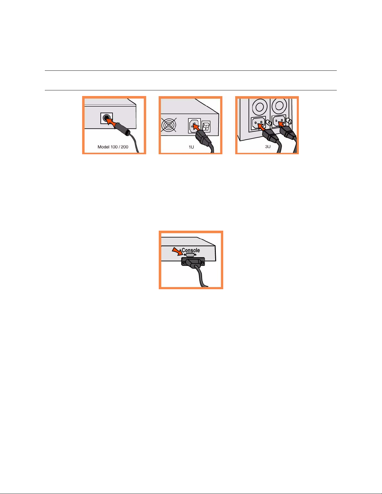
Coloque en la posición de encendido el interruptor de encendido del sistema que se encuentra en la
parte frontal del dispositivo Steelhead.
CAUTION: En todos los entornos eléctricos europeos, deberá conectar a tierra la lengüeta verde o amarilla del cable
de alimentación. De lo contrario, se podría producir un choque eléctrico..
4. Conexión con el Dispositivo Steelhead
Enchufe el cable serial en el puerto de la consola y en una terminal.
Asegúrese de que los ajustes del puerto de la consola sean los siguientes: 9600, 8 bits de datos, sin
paridad, un bit de parada, sin control de flujo.
Inicie el programa de emulación de terminal (por ejemplo, HyperTerminal o Tera Term Pro).
En indicador de inicio de sesión, escriba admin. La contraseña predeterminada es password..
El asistente de configuración se inicia automáticamente al iniciar la sesión en la interfaz de línea de
comandos de Steelhead por primera vez.
Siga las indicaciones que aparecen en pantalla para configurar la red y la interfaz en ruta para el
dispositivo Steelhead.
Confirme la configuración y, a continuación, escriba exit para cerrar la sesión con el sistema.
5. Conexión del Dispositivo Steelhead con la red
Asegúrese de usar los cables correctos para conectar el dispositivo con la red:
– Cables de conexión directa: puertos principal y LAN con el conmutador LAN.
– Cable de conexión cruzada: puerto WAN a enrutador WAN.
Enchufe el cable de conexión directa al puerto principal del dispositivo Steelhead y al conmutador
LAN.
22 1 - INSTALLING THE STEELHEAD APPLIANCE
Page 23
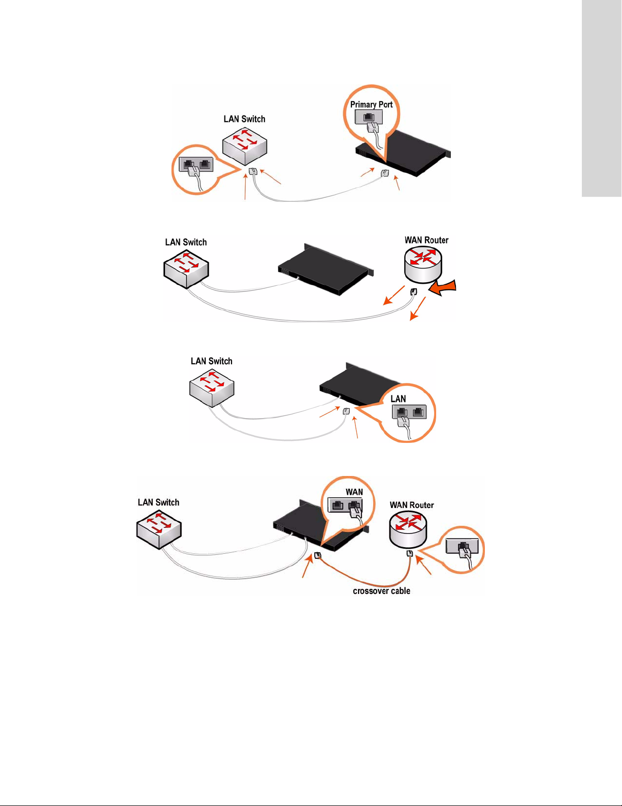
Puede ser cualquier puerto del conmutador LAN configurado para conectarse con el host.
Identifique el cable de conexión directa que conecta el conmutador LAN con el enrutador WAN;
desenchufe el extremo conectado al enrutador WAN.
1 INSTALLING THE STEELHEAD APPLIANCE
Enchufe el extremo del cable que desconectó del enrutador WAN en el puerto LAN del dispositivo
Steelhead.
Enchufe el cable de conexión cruzada suministrado en el puerto WAN del dispositivo Steelhead y el
enrutador WAN.
6. Comprobación de las conexiones
Controle el estado de los indicadores LED para comprobar si el dispositivo está correctamente
conectado.
Para comprobar las conexiones, escriba el comando ping en la interfaz de administración.
ping -I <primary-IP-address> <primary-default-gateway>
ping -I <in-path-IP-address> <in-path-default-gateway>
GETTING STARTED GUIDE 23
Page 24

7. Conexión con la consola de administración
Escriba el URL de Management Console en el cuadro de dirección del explorador de Internet:
http://host.domain o https://host.domain
Aparece la página de bienvenida de Management Console.
Escriba admin, en el cuadro de texto Account (Cuenta).
En el cuadro de texto Password (Contraseña), escriba la contraseña asignada.
Haga clic en Login (Inicio de sesión) para abrir la página de inicio.
Si desea obtener las últimas actualizaciones del software y la documentación de Steelhead, visite http://
www.riverbed.com.
Schnellinstallation des Steelhead-Geräts
Im Kapitel wird beschrieben, wie Sie das Steelhead-Gerät schnell in einer integrierten Konfiguration
installieren und konfigurieren können. In einer integrierten Konfiguration wird das Steelhead-Gerät im
direkten Pfad des Clients und Servers konfiguriert. Weitere Informationen zu den Konfigurationsoptionen
finden Sie auf der Riverbed Documentation CD.
1. Erste Schritte
Lesen Sie die Produkthinweise unter http://www.riverbed.com/support, die wichtige Informationen zu
dieser Version enthalten.
Überprüfen Sie den Packzettel, um sicherzustellen, dass alle erforderlichen Teile vorhanden sind.
Stellen Sie sicher, dass genügend Platz auf einem 19-Zoll-Rack mit zwei oder vier Säulen vorhanden
ist. (Das Modell 50/100/200/300 muss nicht in einem Rack montiert werden.)
Stellen Sie sicher, dass die Raumtemperatur nicht höher als 35 ºC (95 ºF) ist.
Zum Montieren des Geräts in einem Rack benötigen Sie einen Kreuzschlitzschraubenzieher.
Stellen Sie die erforderlichen Informationen zusammen:
Host- und Domänenname, IP-Adresse, DNS-Server, Standardgateway
Primäre Schnittstellengeschwindigkeit und Duplexeinstellungen
IP-Adresse der integrierten Schnittstellen, Netzmaske und Standardgateway
Integrierte LAN- und WAN-Schnittstellengeschwindigkeit und Duplexeinstellungen
2. Montage in einem Rack
Wenn das Modell mit einer Blende versehen ist, entfernen Sie diese.
Wenn das Modell Schienen erfordert, bringen Sie diese an den Seiten des Geräts an. Weitere
Informationen finden Sie auf der Riverbed Documentation CD.
Richten Sie die Befestigungslöcher an den Kanten mit den Befestigungslöchern im Rack aus.
Setzen Sie die Schrauben an den Seiten des Geräts ein und ziehen Sie diese an.
24 1 - INSTALLING THE STEELHEAD APPLIANCE
Page 25
NOTE: Do not cover the air vents on the top of the Model 50/100/200/300. Doing so will cause restricted air flow and
may damage unit or reduce performance. The Model 50/100/200/300 is a desktop model; it does not need to be
mounted to a rack.
3. Stromanschluss
Wenn Ihr Modell mit einem Hauptnetzschalter (an der Rückseite) ausgestattet ist, schalten Sie diesen
aus.
Stecken Sie das Stromkabel in das Gerät und in eine Steckdose ein.
Wenn Ihr Modell mit einem Hauptnetzschalter ausgestattet ist, schalten Sie diesen ein.
Drücken Sie den Systemnetzschalter an der Vorderseite der Steelhead.
CAUTION: In allen europäischen Ländern muss die grün-gelbe Klemme über das Stromkabel geerdet werden.
Ansonsten kann ein elektrischer Stromschlag verursacht werden.
1 INSTALLING THE STEELHEAD APPLIANCE
4. Verbinden des Steelhead-Geräts
Stecken Sie das serielle Kabel in den Konsolenanschluss und ein Terminal ein.
Überprüfen Sie die Einstellungen für den Konsolenanschluss: 9600, 8 Datenbits, keine Parität, 1
Stoppbit, keine Flusssteuerung.
Starten Sie das Terminalemulationsprogramm (z.B. HyperTerminal oder Tera Term Pro).
Geben Sie an der Anmeldeaufforderung admin ein. Das Standardkennwort ist password.
Der Konfigurations-Assistent wird automatisch gestartet, wenn Sie sich das erste Mal über die
Steelhead-Befehlszeile anmelden.
Folgen Sie den Anweisungen, um das Netzwerk und die integrierten Schnittstelleneinstellungen für
das Steelhead-Gerät zu konfigurieren.
Bestätigen Sie die Einstellungen und geben Sie anschließend exit ein, um sich abzumelden.
GETTING STARTED GUIDE 25
Page 26
5. Verbinden des Steelhead-Geräts mit dem Netzwerk
Stellen Sie sicher, dass Sie die richtigen Kabel für die Netzwerkverbindung verwenden:
– Durchgangskabel: Primäre und LAN-Ports zu LAN-Switch.
– Übergangskabel: WAN-Port zu WAN-Router.
Stecken Sie das Durchgangskabel in den primären Port des Steelhead-Geräts und des LAN-Switches
ein. Hierbeikann es sich um einen beliebigen Port auf dem LAN-Switch handeln, der für die
Verbindung mit einem Host konfiguriert ist..
Ziehen Sie das Durchgangskabel, das den LAN-Switch mit dem WAN-Router verbindet, aus dem
WAN -R ou te r.
Stecken Sie das Durchgangskabel anschließend in den LAN-Port des Steelhead-Geräts ein.
Stecken Sie das Übergangskabel in den WAN-Port des Steelhead-Geräts und den WAN-Router ein.
26 1 - INSTALLING THE STEELHEAD APPLIANCE
Page 27

6. Überprüfen der Verbindungen
Überprüfen Sie die LED-Statusanzeigen, um sicherzustellen, dass das Gerät richtig angeschlossen ist.
Um die Verbindungen zu überprüfen, geben Sie den Befehl ping in der Befehlszeile ein:
ping -I <primary-IP-address> <primary-default-gateway>
ping -I <in-path-IP-address> <in-path-default-gateway>
7. Verbinden der Verwaltungskonsole
Geben Sie den URL zur Verwaltungskonsole in den Webbrowser ein:
http://host.domain oder https://host.domain
Die Willkommensseite der Verwaltungskonsole wird angezeigt.
Geben Sie admin im Textfeld Konto ein.
Geben Sie im Textfeld Kennwort Ihr Kennwort ein.
Klicken Sie auf Login, um die Startseite anzuzeigen.
1 INSTALLING THE STEELHEAD APPLIANCE
Sie finden die neueste Steelhead-Gerätesoftware und Dokumentation unter http://www.riverbed.com.
Guide d'installation rapide de l'appareil Steelhead
Ce chapitre décrit les processus d'installation et de configuration rapides de l'appareil Steelhead dans une
configuration interne. Dans une configuration interne, l'appareil Steelhead se trouve dans la trajectoire
directe du client au serveur. Pour tout renseignement sur des options de configuration supplémentaires,
voir le CD de Documentation Riverbed.
1. Mise en route
Veuillez lire les instructions d’utilisation relatives au produit, qui sont situées sur le site
http://www.riverbed.com/support. Elles contiennent d'importantes informations sur cette version.
Vérifiez sur votre bon de livraison que toutes les pièces nécessaires vous ont bien été livrées.
Vérifiez que vous disposez d'un espace suffisant pour installer l'appareil sur un support de 50 cm à
deux ou quatre montants. (Il n'est pas nécessaire de monter le modèle 50/100/200/300 sur un
support.)
Assurez-vous que la température ambiante ne dépasse pas 35º C (95º F).
Vous devrez utiliser un tournevis à empreinte cruciforme standard pour monter l'appareil sur un
support.
Vous devrez fournir les informations suivantes :
le nom d'hôte et de domaine, l'adresse IP, le serveur DNS, la passerelle par défaut
les paramètres de débit et de duplex de l'interface principale
l'adresse IP, le masque de sous réseau et la passerelle par défaut de l'interface interne
les paramètres de débit et de duplex de l'interface interne du réseau local (LAN) et du réseau
étendu (WAN)
GETTING STARTED GUIDE 27
Page 28
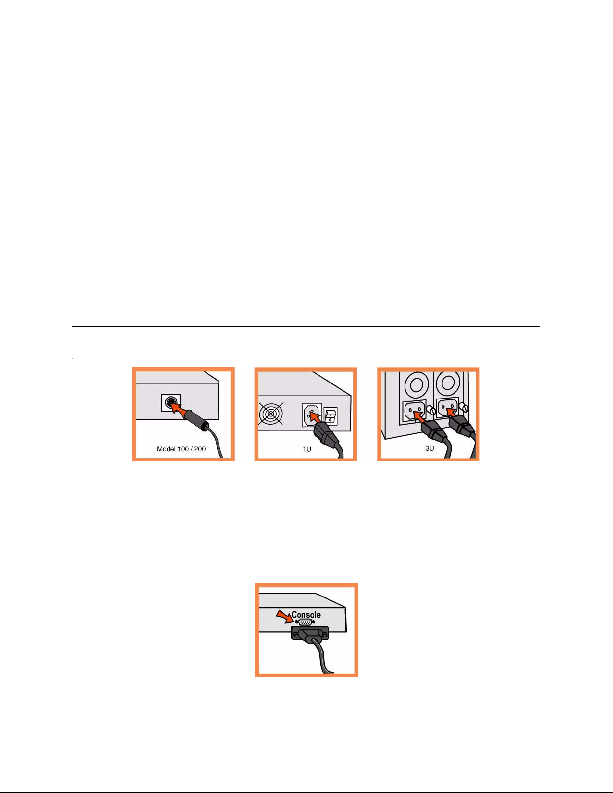
2. Montage sur un support
Si votre appareil est doté d'un cadre, veuillez le retirer.
Si des rails sont requis, fixez-les sur chaque côté de l'appareil. Pour plus de détails, voir le CD de
documentation Riverbed.
Alignez les trous de vis des brides aux trous de vis du support.
Insérez les vis sur chaque côté de l'appareil et serrez-les.
3. Branchement sur secteur
Si votre modèle est équipé d’un interrupteur d’alimentation principal, mettez-le en position Arrêt
(OFF) (sur le panneau arrière).
Branchez le(s) cordon(s) d’alimentation dans l’appareil et dans une prise secteur.
Si votre modèle est équipé d’un interrupteur d’alimentation principal, appuyez dessus pour le mettre
en position Marche (ON).
Appuyez sur l’interrupteur d’alimentation système situé à l’avant de l’appareil.
AVERTISSEMENT: Dans toutes les installations électriques en Europe, la fiche jaune/verte du cordon d'alimentation
doit être mise à la terre. En ne mettant pas la fiche jaune/verte à la terre, vous créez un risque de choc électrique..
4. Branchement à l'appareil Steelhead
Branchez le câble série dans le port Console et à un terminal.
Vérifiez que les paramètres du port Console sont bien les suivants : 9600, 8 bits de données, sans parité,
1 bit d'arrêt, pas de contrôle de flux.
Lancez votre programme d'émulation de terminal (par exemple, HyperTerminal ou Tera Term Pro).
À l'invite, entrez admin. Le mot de passe par défaut est password.
L'assistant de configuration est automatiquement lancé à la première ouverture de session de
l'interface de ligne de commande Steelhead.
28 1 - INSTALLING THE STEELHEAD APPLIANCE
Page 29
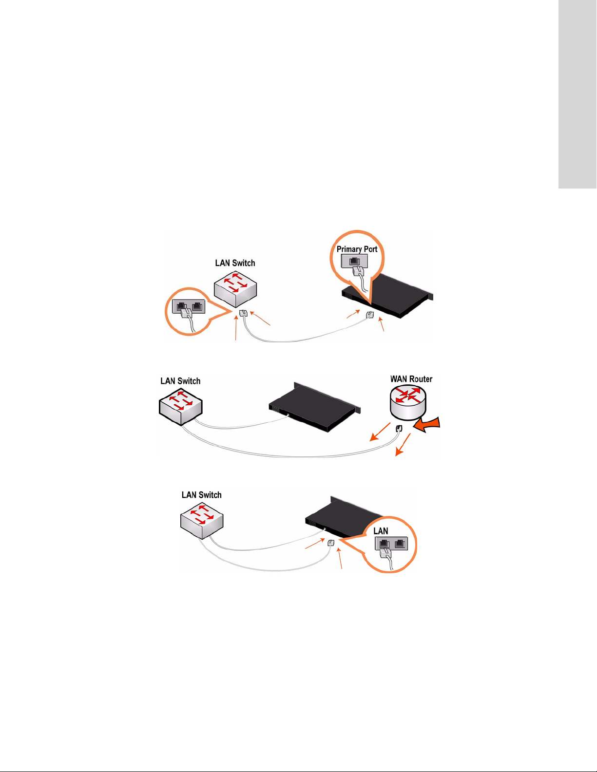
Suivez les invites pour configurer le réseau et les paramètres de l'interface interne de l'appareil
Steelhead.
Confirmez vos paramètres, puis tapez exit pour quitter le système.
5. Connexion de l'appareil Steelhead à votre réseau
Vérifiez que vous utilisez les câbles adéquats pour la connexion à votre réseau :
– Câbles droits : Connexion des ports principal et LAN à l'interrupteur LAN.
– Câble croisé : Connexion du port WAN au routeur WAN.
Branchez le câble droit dans le port principal de l'appareil Steelhead et dans l'interrupteur LAN. (Il
peut s'agir de tout port de votre interrupteur LAN configuré pour la connexion à un hôte.).
1 INSTALLING THE STEELHEAD APPLIANCE
Repérez le câble droit qui connecte l'interrupteur LAN au routeur WAN ; débranchez l'extrémité qui
est connectée au routeur WAN.
Branchez le câble droit que vous avez débranchez du routeur WAN dans le port LAN de l'appareil
Steelhead.
GETTING STARTED GUIDE 29
Page 30
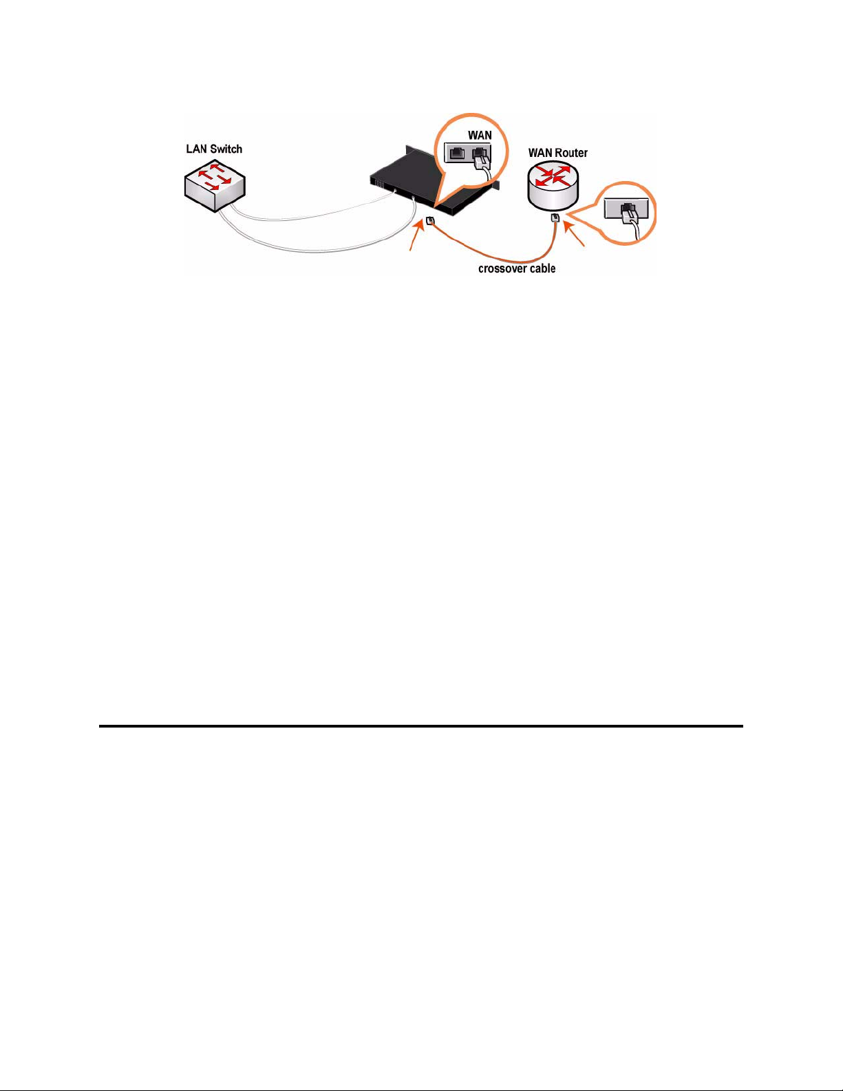
Branchez le câble croisé fourni dans le port WAN de l'appareil Steelhead et dans le routeur WAN.
6. Vérification des branchements
Pour vous assurer que l'appareil est bien branché, vérifiez que la DEL d'état s'allume.
Pour vérifier les branchements, entrez la commande ping dans l'interface de gestion:
ping -I <primary-IP-address> <primary-default-gateway>
ping -I <in-path-IP-address> <in-path-default-gateway>
7. Connexion à la Console de gestion
Entrez l'URL de la Console de gestion dans la zone d'adresse de votre navigateur Web :
http://host.domain ou https://host.domain
La Console de gestion apparaît, et la page de bienvenue est affichée.
Dans la zone de texte dédiée au compte, tapez admin.
Dans la zone de texte réservée au mot de passe, tapez votre mot de passe.
Cliquez sur Login (Ouvrir une session) pour afficher la page d'accueil.
Des mises à jour de logiciel et de documentation relatifs à l'appareil Steelhead sont disponibles sur le site
http://www.riverbed.com.
Installazione dell'Apparecchiatura Steelhead
In questo capitolo viene descritto come installare e configurare rapidamente l'apparecchiatura Steelhead nel
caso in cui venga posizionata nel percorso diretto tra il client e il server. Per informazioni su altre opzioni
di configurazione, consultare il Documentation Set CD.
1. Operazioni preliminari
Leggere le note sulla versione del prodotto disponibili all'indirizzo http://www.riverbed.com/support che
contengono informazioni importanti relative a questa versione specifica.
Verificare che nella confezione siano presenti tutti i componenti necessari.
Assicurarsi di disporre di spazio sufficiente in un rack da 19 pollici a due o quattro montanti
(il modello 50/100/200/300 non richiede l'installazione in un rack).
30 1 - INSTALLING THE STEELHEAD APPLIANCE
Page 31
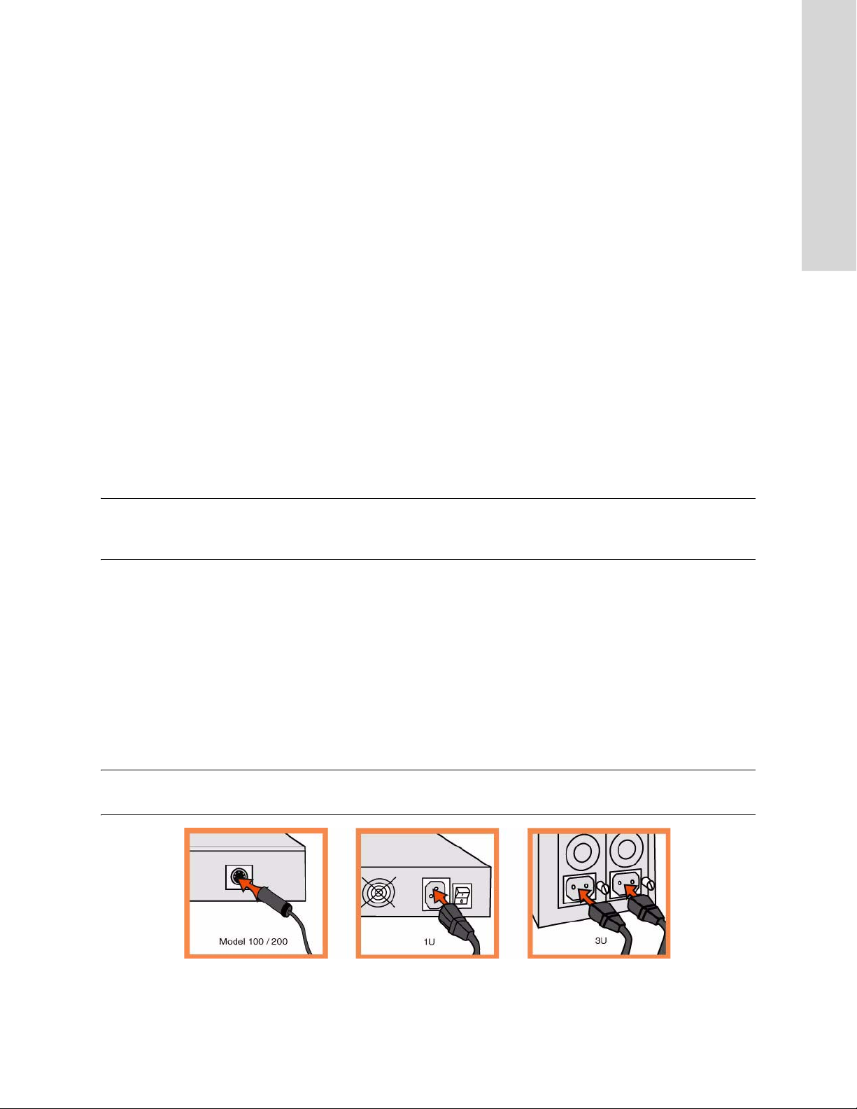
Assicurarsi che la temperatura ambiente non superi 35 ºC.
Assicurarsi di disporre di un cacciavite a croce standard da utilizzare per l'installazione
dell'apparecchiatura nel rack.
Raccogliere le informazioni necessarie:
nome del dominio e host, indirizzo IP, server DNS, gateway predefinito
Impostazioni duplex e velocità dell'interfaccia principale
Indirizzo IP, maschera di rete e gateway predefinito dell'interfaccia del percorso diretto tra client e server
Impostazioni duplex e velocità dell'interfaccia principale LAN e WAN del percorso diretto tra
client e server
2. Installazione nel rack
Se il modello è dotato di frontalino, rimuoverlo.
Se il modello richiede l'uso di guide, applicarle a entrambi i lati dell'apparecchiatura.
Per ulteriori informazioni, consultare la Documentation Set CD.
1 INSTALLING THE STEELHEAD APPLIANCE
Allineare i fori delle viti sulle flangie con quelli sul rack.
Inserire e serrare le viti su entrambi i lati dell'apparecchiatura.
NOTA: Non ostruire le prese d'aria presenti nella parte superiore del modello 50/100/200/300, altrimenti il flusso
d'aria ridotto potrebbe causare danni all'unità o un calo di prestazioni. Il modello 50/100/200/300 è di tipo desktop e
non richiede quindi l'installazione in un rack.
3. Collegamento dell'alimentazione
Se il modello è dotato di interruttore di alimentazione principale, sul pannello posteriore, verificare che
sia nella posizione off.
Collegare il cavo o i cavi di alimentazione all'apparecchiatura e alla presa di corrente CA.
Se il modello è dotato di interruttore di alimentazione principale, premerlo (ON).
Premere l'interruttore di accensione del sistema sul pannello frontale dell'apparecchiatura.
ATTENZIONE. per le installazioni elettriche in Europa è necessario mettere a terra la linguetta giallo/verde del cavo
di alimentazione per evitare possibili scariche elettriche.
GETTING STARTED GUIDE 31
Page 32
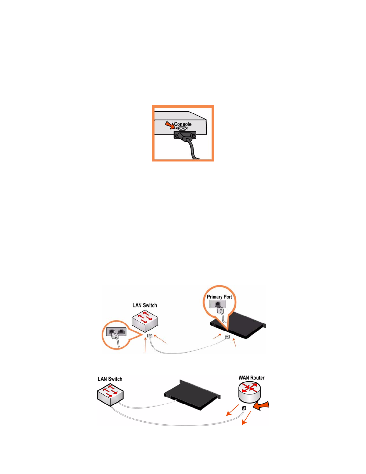
4. Collegamento dell'Apparecchiatura Steelhead
Collegare il cavo seriale alla porta Console e a un terminale.
Verificare che le impostazioni della porta Console siano: 9600, 8 bit di dati, nessuna parità, 1 bit di stop,
nessun controllo del flusso.
Avviare un programma di emulazione del terminale, ad esempio HyperTerminal o Tera Term Pro.
Al prompt di accesso digitare admin. La password predefinita è password.
Al primo accesso all'interfaccia da riga di comando di Steelhead viene automaticamente avviata la
procedura guidata di configurazione.
Attenersi alle istruzioni per configurare la rete e le impostazioni dell'interfaccia del percorso diretto tra
client e server.
Verificare le impostazioni e quindi digitare exit per uscire dal sistema.
5. Collegamento dell'Apparecchiatura Steelhead alla rete
Assicurarsi di utilizzare i cavi appropriati per il collegamento alla rete:
– Cavi dritti: dalle porte LAN e dalla porta principale allo switch LAN.
– Cavo invertito: dalla porta WAN al router WAN.
Collegare un cavo dritto tra la porta principale dell'apparecchiatura Steelhead e lo switch LAN,
utilizzando qualsiasi porta dello switch LAN configurata per il collegamento a un host.
Identificare il cavo dritto che collega lo switch LAN al router WAN e disinserire l'estremità collegata al
router WAN.
32 1 - INSTALLING THE STEELHEAD APPLIANCE
Page 33
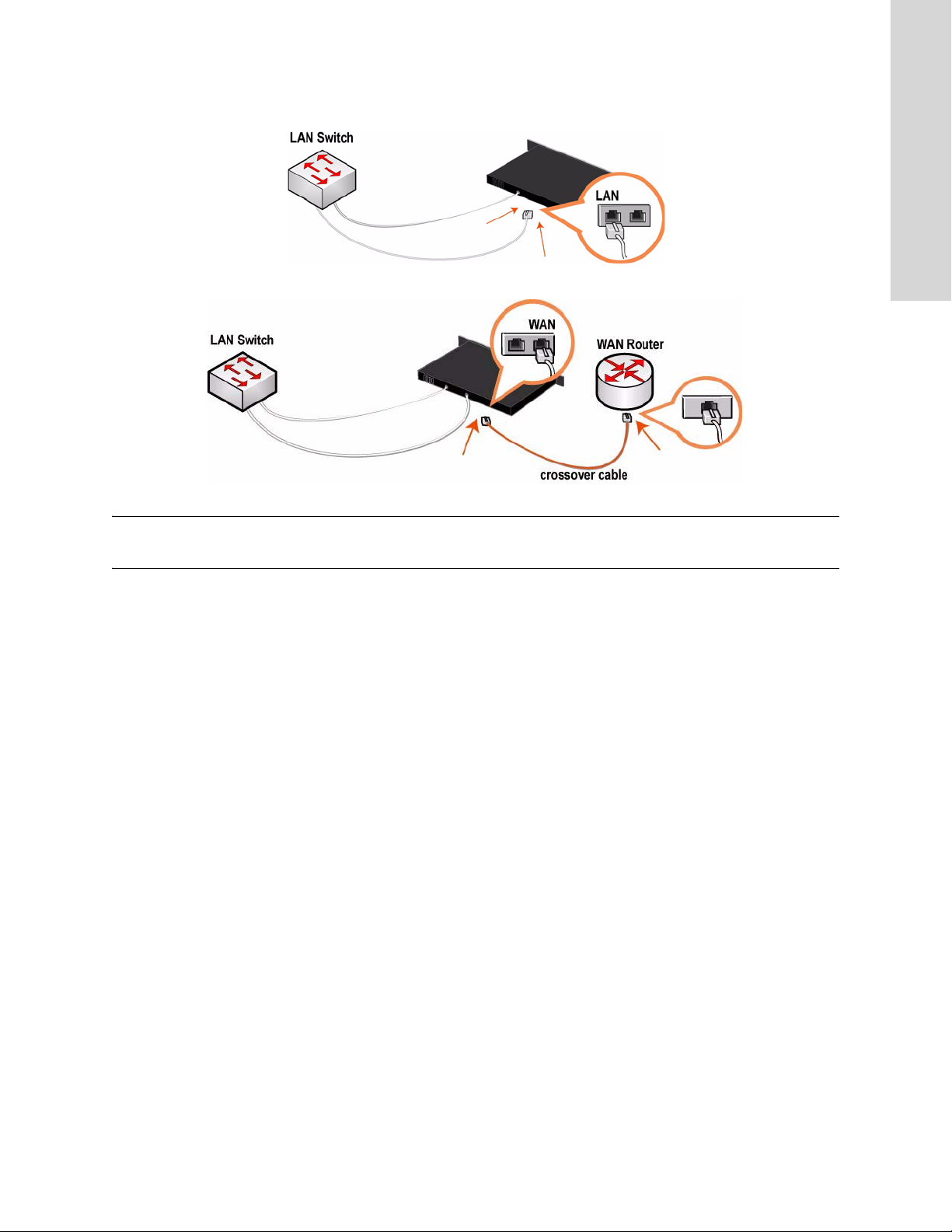
Collegare il cavo dritto appena disinserito dal router WAN alla porta LAN dell'Steelhead appliance.
Utilizzare il cavo invertito fornito per collegare la porta WAN dell'apparecchiatura Steelhead al router WAN.
1 INSTALLING THE STEELHEAD APPLIANCE
NOTA: se si dispone di una scheda Four-Port Copper Gigabit-Ethernet Bypass, ripetere i passaggi di installazione. Per
informazioni dettagliate sull'installazione di schede di bypass aggiuntive, consultare la Bypass Card Installation Guide.
È possibile ottimizzare il traffico WAN utilizzando l'Steelhead appliance.
6. Verifica della connessione
Verificare le luci di stato dei LED per assicurarsi che l'apparecchiatura sia collegata correttamente.
Per verificare le connessioni, immettere il comando ping dall'interfaccia di gestione:
ping -I <indirizzo-IP-principale> <gateway-predefinito-principale>
ping -I <indirizzo-IP-percorso-diretto> <gateway-predefinito-percorso-diretto>
7. Accesso alla console di gestione
Immettere l'URL della console di gestione nella casella dell'indirizzo del browser Web:
http://host.dominio o https://host.dominio
Verrà visualizzata la pagina di benvenuto della console di gestione.
Nella casella di testo Account digitare admin.
Nella casella di testo Password digitare la password assegnata.
Fare clic su Login per visualizzare la pagina iniziale.
È possibile ottenere le ultime versioni del software e della documentazione per l'apparecchiatura Steelhead
all'indirizzo http://www.riverbed.com.
GETTING STARTED GUIDE 33
Page 34
安装
Steelhead Appliance
在本章中
本指南介绍如何按照径内(
Steelhead
。
CD
信息家电是客户端和服务器的直接路径。有关更多配置选项的详情,请参阅
in-path
)配置来快速安装和配置
1. 使用入门
阅读位于
http://www.riverbed.com
检查包装清单,确保收到所有必需的部件。
确定在两柱或四柱
确定环境温度不超过
确定备有用来将信息家电安装到机架的标准十字螺丝刀。
搜集必需的信息:
主机和域名、
主要接口速度和双工设置
英寸机架上有足够的空间。(
19
35º C (95º F)
地址、
IP
的本产品版本说明。此网页包含了有关这 一版本 的重要信息。
。
服务器、默认网关
DNS
Steelhead
50/100/200/300
信息家电。在径内配置中,
Documentation Set
型号不必安装在机架上。)
径内接口
径内
LAN 和 WAN
地址、网络掩码和默认网关
IP
接口速度和双工设置
2. 在机架上安装
如果您的型号备有挡板,请卸下它。
如果您的机型需要护栏,请将护栏装在信息家电的两边。有关详情,请参阅
将轮缘上的螺丝孔对准机架上的螺丝孔。
在信息家电的两边装上并拧紧螺丝。
注:请勿盖住
型号为台式机,不需要安装到机架。
300
50/100/200/300
型号顶部的通风孔,以免造成空气流通不畅,从而损坏设备或降低性能。
3. 连接电源
如果您的型号备有主电源开关,确定它处在关机位置(在后面板上)。
将电源线插接到信息家电和交流电源插座。
Documentation Set CD
50/100/200/
。
如果您的型号备有主电源开关,请按下主电源开关
按下家电前面的系统电源开关。
34 1 - INSTALLING THE STEELHEAD APPLIANCE
(ON)
。
Page 35
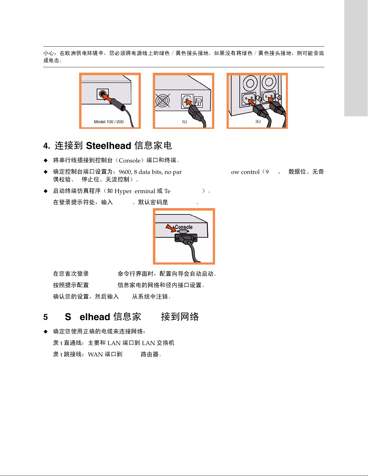
小心:在欧洲供电环境中,您必须将电源线上的绿色/黄色接头接地。如果没有将绿色/黄色接头接地,则可能会造
成电击。
1 INSTALLING THE STEELHEAD APPLIANCE
4. 连接到
将串行线插接到控制台(
确定控制台端口设置为:
偶校验、
启动终端仿真程序(如
在登录提示符处,输入
在您首次登录
按照提示配置
确认您的设置,然后输入
5. 将
Steelhead
Steelhead
停止位、无流控制)。
1
Steelhead
Steelhead
信息家电
Console
9600, 8 data bits, no parity, 1 stop bit, no flow control(9600、8
HyperTerminal 或 Tera Term Pro
admin
命令行界面时,配置向导会自动启动。
信息家电的网络和径内接口设置。
exit
)端口和终端。
。默认密码是
从系统中注销。
password
)。
。
信息家电连接到网络
数据位、无奇
确定您使用正确的电缆来连接网络:
衆
直通线:主要和
t
衆
跳接线:
t
GETTING STARTED GUIDE 35
WA N
LAN
端口到
端口到
WAN
交换机
LAN
路由器。
Page 36
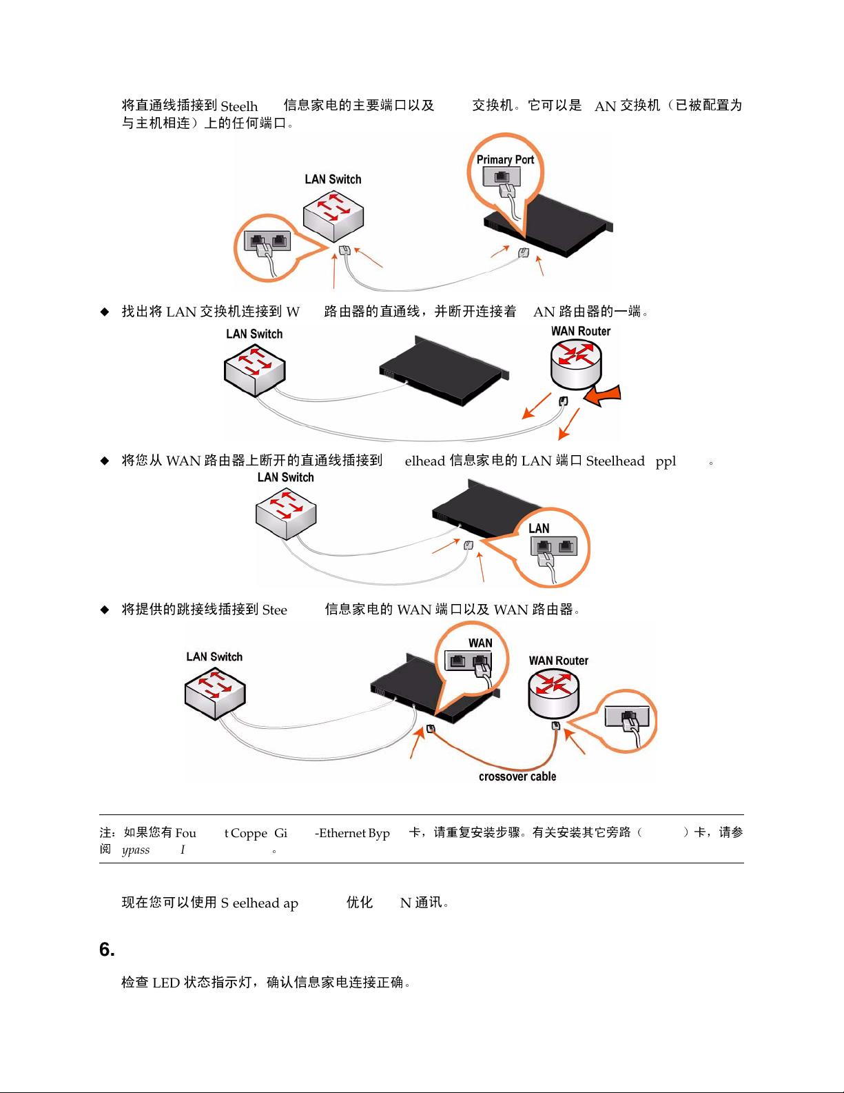
将直通线插接到
与
主机相连)上的任何端口。
找出
将
LAN
交换机连接到
Steelhead
信息家电的主要端口以及
路由器的直通线,并断开连接
WAN
交换机。它可以是
LAN
着
WAN
交换机(已被配置为
LAN
路由器的一端。
将您从
将提供的跳接线插接到
注:如果您有
阅
Bypass Card Installation Guide
路由器上断开的直通线插接到
WAN
Four-Port Copper Gigabit-Ethernet Bypass
Steelhead
。
信息家电的
Steelhead
WAN
信息家电的
端口以及
卡,请重复安装步骤。有关安装其它旁路(
WAN
LAN
路由器。
端口
Steelhead appliance
)卡,请参
bypass
。
现
在您可以使用
Steelhead appliance
优化
WAN
通讯。
6. 检查连接
检查
36 1 - INSTALLING THE STEELHEAD APPLIANCE
LED
状态指示灯
,确认信息家电连接正确。
Page 37
要检查连接,请从管理界面输入
ping -I <主要 IP 地址> <
ping -I <
径内
IP 地址> <
主要默认网关
径内默认网关
ping
>
>
命令:
7. 连接到管理控制台
在
http://host.domain 或 https://host.domain
Web
浏览
器的地址栏中输入
Management Console
(管理控制台)的
URL
1 INSTALLING THE STEELHEAD APPLIANCE
:
Management Console
在
Account
在
Password
单
击
您可以从
(帐户)文本框中,输入
(密码)文本框中,输入您指派的密码。
(登录)以显示主页。
Login
http://www.riverbed.com
会出现,并显示
admin
取得最新
Welcome
(
。
的
Steelhead
欢迎
)页。
信息家电软件和说明文档更新。
설치 Steelhead Appliance
이 가이드에서는 In-Path 구성 방식의 Steelhead 어플라이언스를 신속하게 설 치하고 구성하는 방법을 설
명합니다 . In-Path 구성 방식의 Steelhead 어플라이언스는 클라이언트 및 서버에 대한 직접 경로를 제공
합니다 . 추가 구성 옵션에 대한 자세한 내용은 Documentation Set CD 를 참조하십시오 .
1. 시작하기
http://www.riverbed.com에
가
포함되어 있습니다
패킹 슬립을 확인하여 필요한 모든 부품이 인도되었는지 확인하십시오
.
있는 제품의 릴리스 정보를 읽으십시오. 여기에는 이 릴리스에 대한 중요 정보
.
2
개 또는 4개 포트의
200/300
실내 온도가
랙에 어플라이언스를 설치하려면 표준형 필립스 스크루드라이버가 있어야 합니다
필요한 정보 수집
은 랙에 설치할 필요가 없습니다
35º C(95º F)를
호스트 및 도메인 이름
기본 인터페이스 속도 및 이중 설정
In-Path
In-Path LAN
인터페이스
19
인치 랙을 설치할 수 있는 충분한 공간이 있는지 확인하십시오
.)
초과하지 않도록 주의하십시오
.
:
, IP
주소
, DNS
서버, 기본 게이트웨이
IP
주소, 네트워크 마스크 및 기본 게이트웨이
및
WAN
인터페이스 속도 및 이중 설정
. (
.
2. 랙에 설치
모델에 베젤이 장착되어 있으면 제거하십시오
GETTING STARTED GUIDE 37
.
모델
50/100/
Page 38
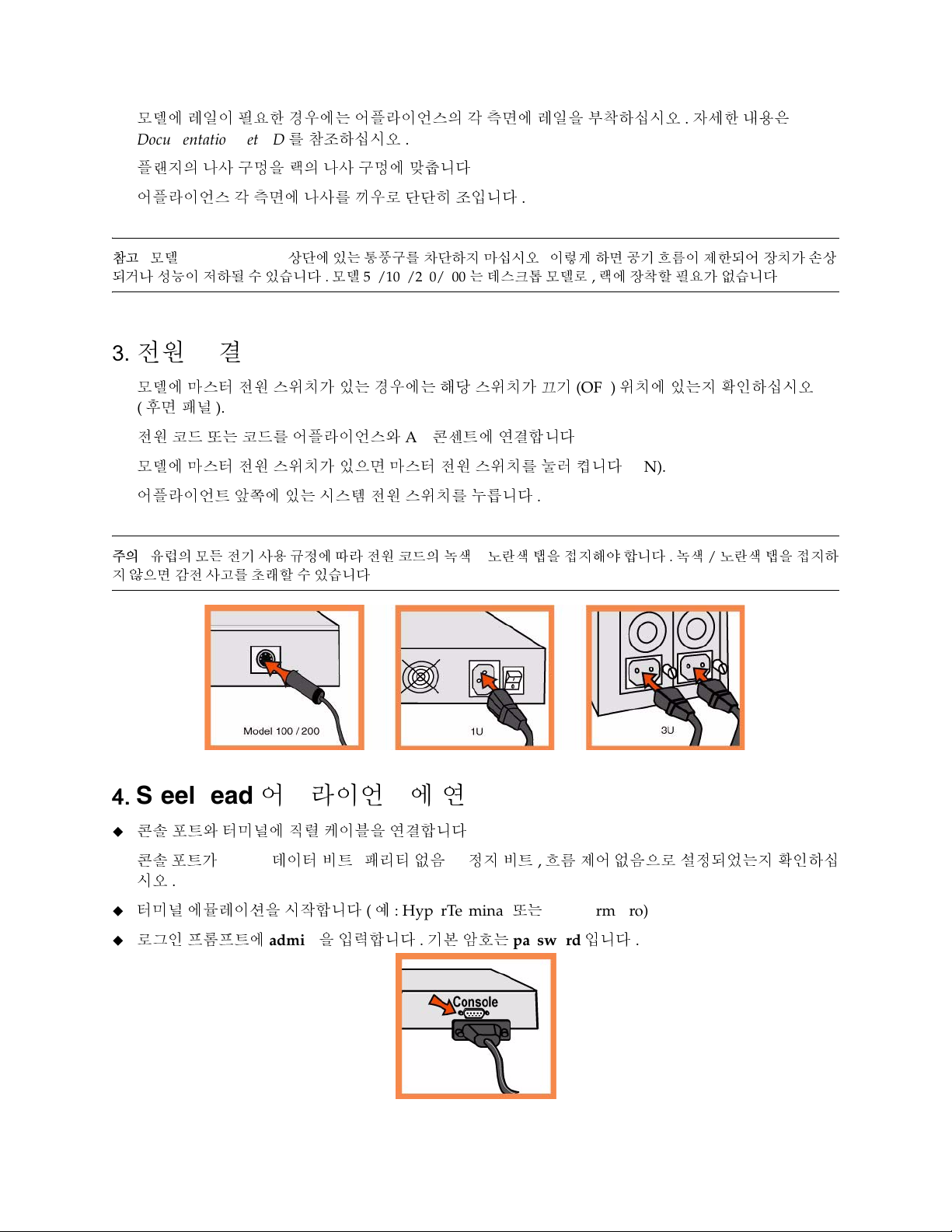
모델에 레일이 필요한 경우에는 어플라이언스의 각 측면에 레일을 부착하십시오. 자세한 내용은
Documentation Set CD
플랜지의 나사 구멍을 랙의 나사 구멍에 맞춥니다
어플라이언스 각 측면에 나사를 끼우로 단단히 조입니다
를 참조하십시오
.
.
.
참고: 모델
되거나 성능이 저하될 수 있습니다. 모델
50/100/200/300
상단에 있는 통풍구를 차단하지 마십시오. 이렇게 하면 공기 흐름이 제한되어 장치가 손상
50/100/200/300는
데스크톱 모델로, 랙에 장착할 필요가 없습니다
.
3. 전원 연결
모델에 마스터 전원 스위치가 있는 경우에는 해당 스위치가 끄기
(
후면 패널
전원 코드 또는 코드를 어플라이언스와
모델에 마스터 전원 스위치가 있으면 마스터 전원 스위치를 눌러 켭니다
어플라이언트 앞쪽에 있는 시스템 전원 스위치를 누릅니다
주의: 유럽의 모든 전기 사용 규정에 따라 전원 코드의 녹색/노란색 탭을 접지해야 합니다. 녹색/노란색 탭을 접지하
지 않으면 감전 사고를 초래할 수 있습니다
).
AC
콘센트에 연결합니다
.
(OFF)
위치에 있는지 확인하십시오
.
(ON).
.
4. Steelhead 어플라이언스에 연결
콘솔 포트와 터미널에 직렬 케이블을 연결합니다
콘솔 포트가
시오
터미널 에뮬레이션을 시작합니다(예
로그인 프롬프트에
38 1 - INSTALLING THE STEELHEAD APPLIANCE
9600, 8
데이터 비트, 패리티 없음
.
: HyperTerminal
admin을
입력합니다. 기본 암호는
.
, 1
정지 비트, 흐름 제어 없음으로 설정되었는지 확인하십
또는
Tera Term Pro) .
password
입니다
.
Page 39
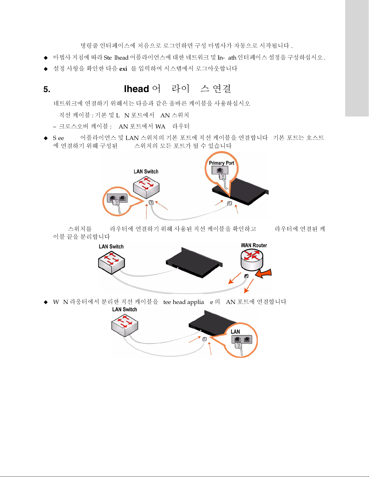
1 INSTALLING THE STEELHEAD APPLIANCE
Steelhead
마법사 지침에 따라
설정 사항을 확인한 다음
명령줄 인터페이스에 처음으로 로그인하면 구성 마법사가 자동으로 시작됩니다
Steelhead
어플라이언스에 대한 네트워크 및
exit를
입력하여 시스템에서 로그아웃합니다
In-Path
5. 네트워크에 Steelhead 어플라이언스 연결
네트워크에 연결하기 위해서는 다음과 같은 올바른 케이블을 사용하십시오
직선 케이블: 기본 및
–
–
크로스오버 케이블
Steelhead
에
연결하기 위해 구성된
어플라이언스 및
LAN
: WAN
LAN
LAN
포트에서
포트에서
LAN
WAN
스위치
라우터
스위치의 기본 포트에 직선 케이블을 연결합니다. 기본 포트는 호스트
스위치의 모든 포트가 될 수 있습니다
.
인터페이스 설정을 구성하십시오
.
.
.
.
LAN
이블
WA N
스위치를
끝을 분리합니다
WAN
라우터에 연결하기 위해 사용된 직선 케이블을 확인하고
.
라웅터에서 분리한 직선 케이블을
Steelhead appliance의 LAN
WAN
라우터에 연결된 케
포트에 연결합니다
.
GETTING STARTED GUIDE 39
Page 40
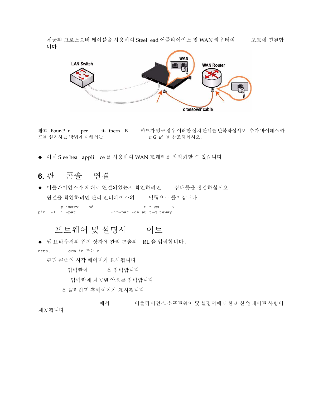
제공된 크로스오버 케이블을 사용하여
니다
.
참고
: Four-Port Copper Gigabit-Ethernet Bypass
드를 설치하는 방법에 대해서는
이제
Steelhead appliance를
Bypass Card Installation Guide를
사용하여
Steelhead
카드가 있는 경우 이러한 설치 단계를 반복하십시오. 추가 바이패스 카
WAN
어플라이언스 및
참조하십시오
WAN
.
라우터의
트래픽을 최적화할 수 있습니다
.
WAN
포트에 연결합
6. 관리 콘솔에 연결
어플라이언스가 제대로 연결되었는지 확인하려면
연결을 확인하려면 관리 인터페이스의
ping -I <primary-IP-address> <primary-default-gateway>
ping -I <in-path-IP-address> <in-path-default-gateway>
ping
LED
명령으로 들어갑니다
7. 소프트웨어 및 설명서 업데이트
웹 브라우저의 위치 상자에 관리 콘솔의
http://host.domain 또는 https://host.domain
관리 콘솔의 시작 페이지가 표시됩니다
Account
Password
Login
http://www.riverbed.com
제공됩니다
입력란에
admin을
입력합니다
입력란에 제공된 암호를 입력합니다
을 클릭하면 홈페이지가 표시됩니다
에서
Steelhead
.
URL을
입력합니다
.
.
.
.
어플라이언스 소프트웨어 및 설명서에 대한 최신 업데이트 사항이
상태등을 점검하십시오
.
.
.
40 1 - INSTALLING THE STEELHEAD APPLIANCE
Page 41

Руководство по быстрой установке устройств Steelhead
В данном руководстве описывается процедура быстрой установки и конфигурирования устройства
Steelhead для случая внутриканальной конфигурации. В случае внутриканальной конфигурации
устройство Steelhead располагается непосредственно в канале, связывающем клиент и сервер.
Подробную информацию о дополнительных вариантах конфигурации см. на компакт
документацией Riverbed
.
1. Начало работы
Прочтите примечания к выпуску изделия на сайте http://www.riverbed.com В них содержится важная
информация об этом выпуске.
Проверьте имеющуюся у вас упаковочную ведомость, чтобы убедиться в наличие всех
необходимых деталей.
Удостоверьтесь, что у вас имеется достаточно места на двух- или четырехпостовой 19-
дюймовой стойке. (Модель 50/100/200/300 не обязательно должна устанавливаться в стойку.)
-
диске с
1 INSTALLING THE STEELHEAD APPLIANCE
Убедитесь, что температура окружающей среды не превышает 35єC (95єF).
Убедитесь, что у вас есть стандартная крестообразная отвертка, с помощью которой вы будете
устанавливать устройство в стойку.
Соберите всю необходимую информацию:
Имя хоста и домена, IP-адрес, DNS сервер, шлюз по умолчанию
Скорость передачи первичного интерфейса и настройки дуплексной передачи данных
IP-адрес внутриканального интерфейса, сетевую маску и шлюз по умолчанию
Скорость передачи внутриканального интерфейса ЛВС и ГВС, а также настройки
дуплексной передачи данных
2. Установка в стойку
Если в вашем устройстве имеется фальш-панель, снимите ее.
Если для имеющейся у вас модели нужны рельсы, прикрепите их с каждой стороны устройства.
Дополнительную документацию см. на компакт
Совместите отверстия для винтов на фланцах с отверстиями для винтов на стойке.
Вставьте и затяните винты с каждой стороны устройства.
Примечание. Не закрывайте вентиляционные отверстия сверху устройства модели 50/100/200/300.
Их закрытие приведет к ограничению потока воздуха из корпуса устройства, что может повредить
устройство или снизить его производительность. Модель 50/100/200/300 – это настольное
устройство, и его не требуется устанавливать в стойку.
-
диске с документацией Riverbed
.
3. Подключение электропитания
Если ваша модель устройства имеет главный выключатель электропитания, убедитесь, что он
находится в положении ВЫКЛ (расположен на задней панели).
GETTING STARTED GUIDE 41
Page 42
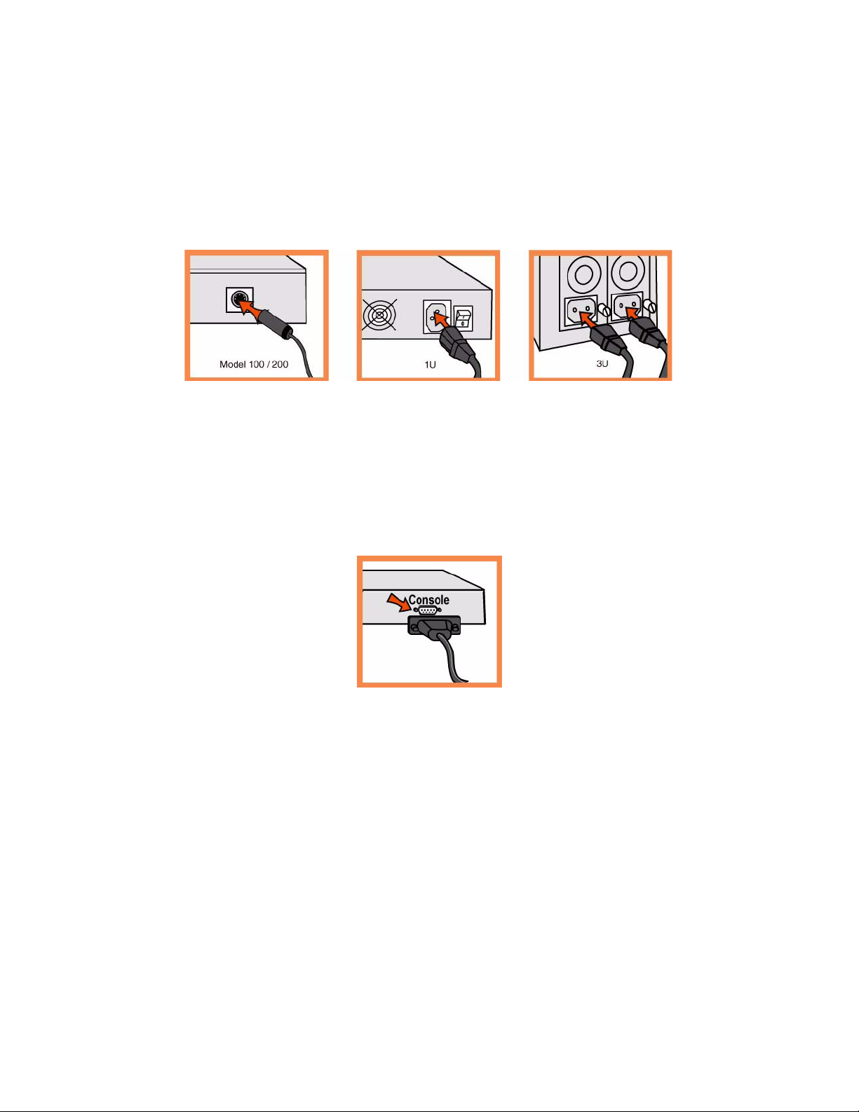
Вставьте сетевой шнур или шнуры в разъем устройства и в розетку сети переменного тока.
Если ваша модель имеет главный выключатель электропитания, нажмите главный выключатель
питания и переведите его в положение ВКЛ (ON).
Нажмите системный выключатель питания на передней панели устройства.
ПРЕДОСТЕРЕЖЕНИЕ. В электросетях всех европейских стран требуется заземлять зеленую/
желтую клемму на сетевом шнуре. Если не заземлить зеленую/желтую клемму, это может привести
к поражению электрическим током.
4. Подключение к устройству Steelhead
Вставьте кабель последовательного интерфейса в порт консоли и в разъем терминала.
Убедитесь, что настройки порта консоли следующие: 9600, 8 бит данных, отсутствие паритета, 1
стоповый бит, нет контроля передачи.
Запустите программу эмуляции терминала (например, HyperTerminal или Tera Ter m P r o ) .
Когда появится приглашение на загрузку, впечатайте admin. Пароль по умолчанию – password.
Мастер конфигурирования запускается автоматически при первом входе в интерфейс
командной строки Steelhead.
Следуйте появляющимся подсказкам для конфигурирования сети и установки настроек
внутриканального интерфейса для устройства Steelhead.
Подтвердите свои настройки, затем наберите exit для выхода из системы.
5. Подключение устройства ЦКА к вашей сети
Убедитесь в том, что для подключения к сети используются правильные кабели:
Прямые кабели: первичный и ЛВС порты к коммутатору ЛВС.
Перекрестный кабель: порт ГВС к маршрутизатору ГВС.
42 1 - INSTALLING THE STEELHEAD APPLIANCE
Page 43
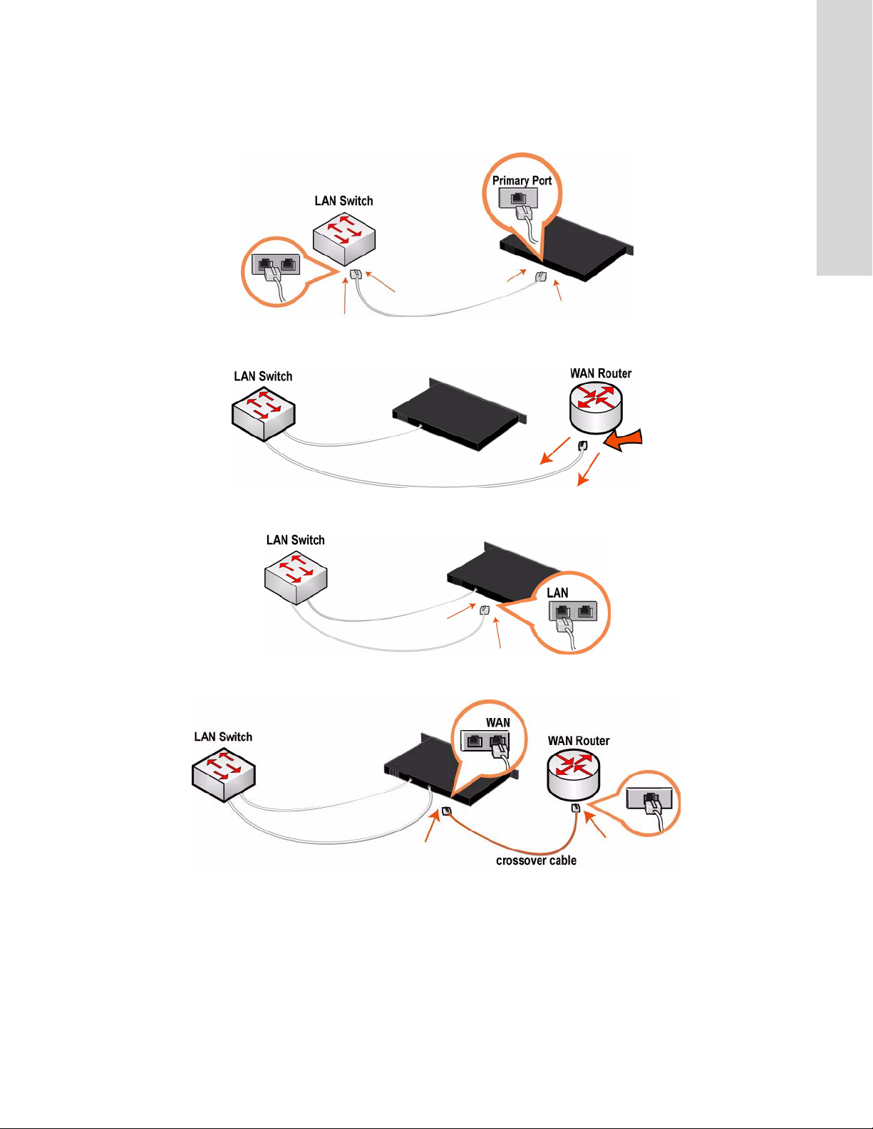
Вставьте разъемы прямого кабеля в первичный порт устройства Steelhead и порт коммутатора
ЛВС. Это может быть любой порт на вашем коммутаторе ЛВС, сконфигурированном для
подключения к хосту.
Найдите прямой кабель, соединяющий ваш коммутатор ЛВС и маршрутизатор ГВС, и
отсоедините разъем, присоединенный к маршрутизатору ГВС.
1 INSTALLING THE STEELHEAD APPLIANCE
Вставьте разъем прямого кабеля, который вы отсоединили от маршрутизатора ГВС, в порт ЛВС
устройства Steelhead.
Взяв затем перекрестный кабель, вставьте один его разъем в порт ГВС устройства Steelhead, а
другой - в порт маршрутизатора ГВС.
Проверьте свечение светодиодов состояния, чтобы убедиться в надлежащем подключении
устройства.
6. Проверка сделанных соединений
Проверьте свечение светодиодов состояния, чтобы убедиться в надлежащем подключении
устройства.
GETTING STARTED GUIDE 43
Page 44

Для проверки сделанных соединений введите с интерфейса администрирования команду ping:
ping -I <primary-IP-address> <primary-default-gateway>
ping -I <in-path-IP-address> <in-path-default-gateway>
7. Подключение к консоли администрирования
Введите URL для консоли администрирования в поле местоположения на вашем веб-браузере:
http://host.domain or https://host.domain
Появится консоль администрирования и отобразится страница с приглашением.
В текстовое поле Account (Учетная запись) наберите admin.
В текстовое поле Password (Пароль) наберите выданный вам пароль.
Нажмите на кнопку Login для отображения главной страницы.
Вы можете получить самые последние версии ПО для устройств Steelhead и обновление
документации на странице http://www.riverbed.com.
44 1 - INSTALLING THE STEELHEAD APPLIANCE
Page 45

CHAPTER 2 Installing and Deploying
Steelhead Mobile
2 INSTALLING AND DEPLOYING STEELHEAD
In This Chapter
This chapter describes how to quickly install and deploy Steelhead Mobile in English and other languages.
For detailed information about installing and configuring the Steelhead Mobile, see the Steelhead Mobile
Controller Installation Guide and the Steelhead Mobile Controller User’s Guide.
Installing and Deploying Steelhead Mobile
This section describes how to quickly install, configure, and deploy Steelhead Mobile. For detailed
information, see the Documentation Set CD.
Overview
Steelhead Mobile enables you to optimize TCP traffic to remote users who are accessing your network using
any type of remote access (for example, dial-up, broadband, and wireless). A Steelhead Mobile deployment
consists of the following components: the Mobile Controller, the Mobile Client, and the Steelhead appliance.
M
OBILE
GETTING STARTED GUIDE 45
Page 46
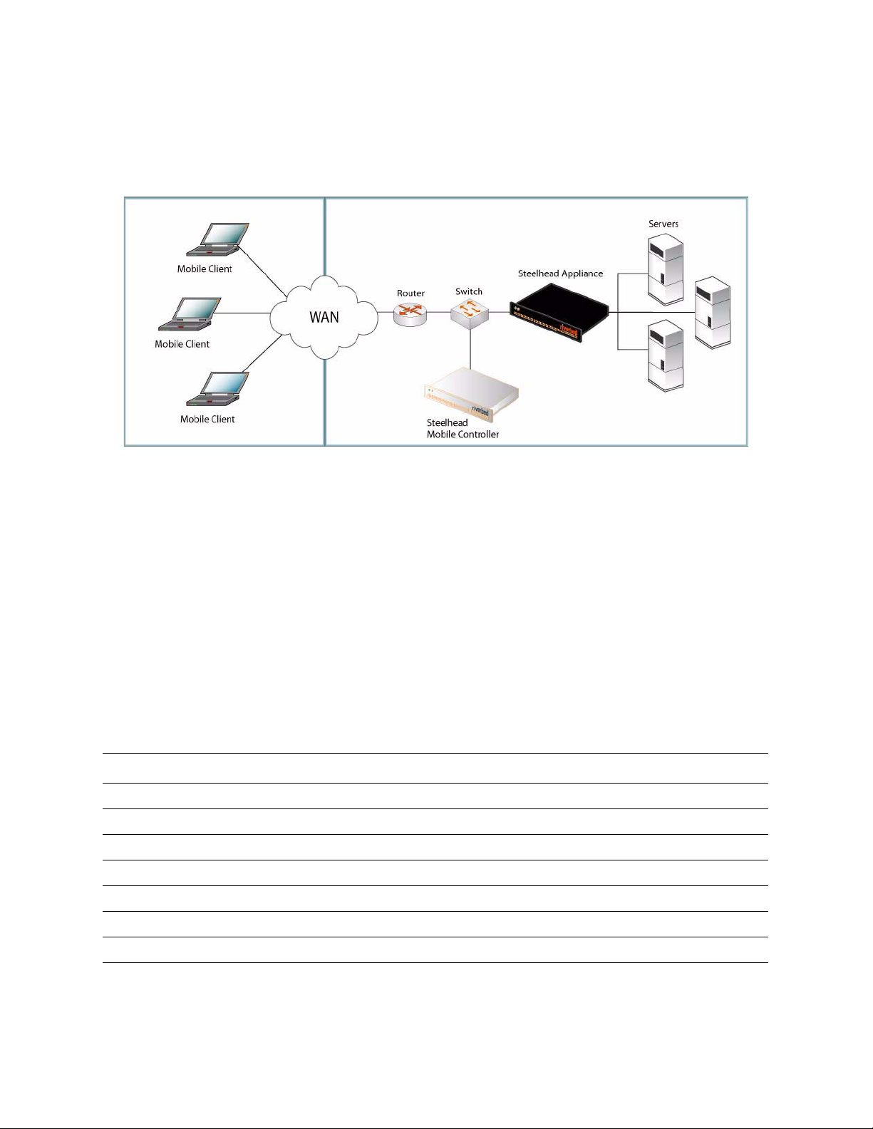
The following is an example of a typical Steelhead Mobile installation. The Mobile Controller is located at
the main data center. All Mobile Clients communicate with the Mobile Controller for management and
reporting purposes. If you have servers at multiple locations, you install server-side Steelhead appliances
at the data centers or branches.
Figure 2-1. Typical Steelhead Mobile Deployment
For detailed information about Steelhead Mobile deployment options, see the Steelhead Mobile Controller
Installation Guide.
1. Getting Started
Read the release notes for the product at http://www.riverbed.com. They contain important information
about this release.
Check your packing slip to make sure that you have all the necessary parts.
Make sure you have adequate space on a two or four post, 19-inch rack.
Make sure that the ambient temperature does not exceed 35º C (95º F).
Make sure you have a standard Phillips screwdriver to install the appliance to a rack.
Be prepared to have values for the parameters listed in the following checklist:
Appliance Parameter
Mobile Controller Host Name
IP Address
Net Mask
Default Gateway (the WAN gateway)
Primary DNS Server (Domain Name Server IP address)
Domain Name
Administrator Password
46 2 - INSTALLING AND DEPLOYING STEELHEAD MOBILE
Page 47

Mobile Client Data Store Size. At least 1 GB of disk space is required for the data store. The default value
is 10 MB.
NOTE: You only need this value if you choose not to use the default MSI package
(containing default acceleration and endpoint policies) that ships with Steelhead Mobile.
Typically, administrators deploy Steelhead Mobile using the default values provided with
the product and modify them after they have deployed Steelhead Mobile to their Mobile
Clients.
Maximum Log Size. The default value is 5000 KB.
NOTE: You only need this value if you choose not to use the default MSI package
(containing default acceleration and endpoint policies) that ships with Steelhead Mobile.
Maximum Number of Log Files. The default value is 2.
NOTE: You only need this value if you choose not to use the default MSI package
(containing default acceleration and endpoint policies) that ships with Steelhead Mobile.
2 INSTALLING AND DEPLOYING STEELHEAD
VPN Port Number. When you deploy Steelhead Mobile components, you need to ensure
that the VPN tunnel is not optimized. If the VPN tunnel uses TCP for transport, when you
configure the acceleration policy, add a pass-through rule for the VPN port number
connected to by the client. Depending on your deployment scenario, this rule might be the
first rule in the list.
For details about acceleration policies, see the Steelhead Mobile Controller User’s Guide.
VPNs that use IPSec as the transport protocol do not need a pass-through rule. This is
because IPSec is its own non-TCP/IP protocol and, by default, the Steelhead appliances do
not optimize it.
For detailed information about pass-through rules, see the Steelhead Mobile Controller User’s
Guide
IMPORTANT: The default MSI package that ships with Steelhead Mobile is designed to be suitable for most network
environments. Typically, you can install and deploy Steelhead Mobile without modifying the default policies that ship
with the product. Consider deploying Steelhead Mobile to your Mobile Clients using the default policies provided, and
modifying them only if necessary.
Make sure you have enough memory on your Mobile Clients to run Steelhead Mobile.
Data Store Size (GB) Memory Usage (MB)
181
M
OBILE
2100
5112
10 161
15 171
20 228
GETTING STARTED GUIDE 47
Page 48
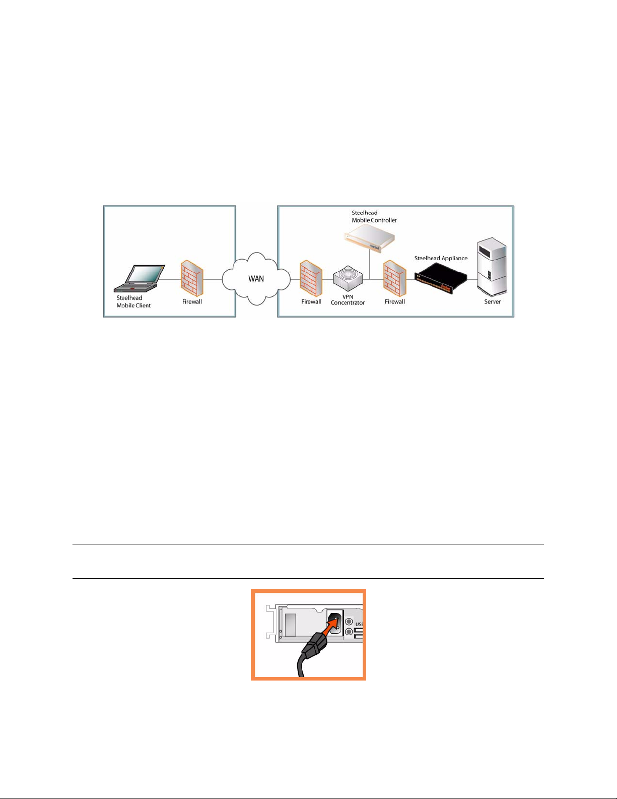
2. Deploying Steelhead Mobile in Environments with Firewalls
If you need a solution for remote access users only, a location for the Mobile Controller might be in the DMZ
next to a VPN concentrator with firewalls on each side. Users who need access to the Mobile Controller can
connect to it from outside the DMZ zone. This scenario requires that the client-side network firewall have
port 7801 available. The server-side firewall must have ports 22, 80, 443, 7800 and 7870 open.
If you are using application control, you need to allow rbtdebug.exe, rbtmon.exe, rbtsport.exe, and
shmobile.exe.
Figure 2-2. Steelhead Mobile Deployment in the DMZ
3. Installing on a Rack
If your model has a bezel, remove it.
Align the screw holes on the flanges with the screw holes on the rack.
Insert and tighten the screws on each side of the appliance.
4. Connecting the Power
If your model has a master power switch, make sure it is in the off position (on the rear panel).
Plug the power cord or cords into the Mobile Controller and an AC outlet.
If your model has a master power switch, press in the master power switch (ON).
Press in the system power switch on the front of the Mobile Controller.
CAUTION: In all European electrical environments, you must ground the Green/Yellow tab on the power cord. If you
do not ground the Green/Yellow tab, it can cause electrical shock.
48 2 - INSTALLING AND DEPLOYING STEELHEAD MOBILE
Page 49
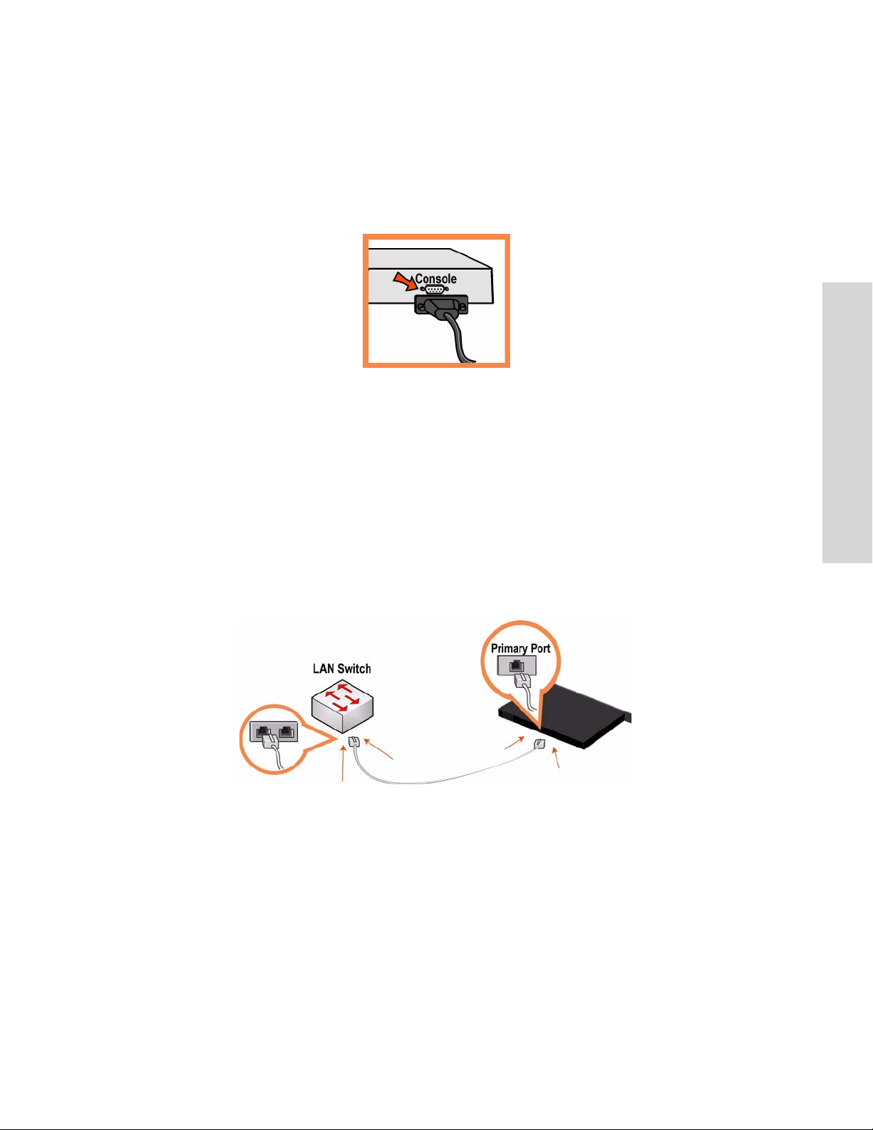
5. Connecting to the Mobile Controller
Plug the serial cable into the Console port and a terminal.
Make sure the Console port settings are: 9600, 8 data bits, no parity, 1 stop bit, no flow control.
Start your terminal emulation program (for example, HyperTerminal or Tera Term Pro).
At the login prompt, type admin. The default password is password.
6. Configuring the Mobile Controller
The configuration wizard automatically starts when you log into the command-line interface for the
first time.
2 INSTALLING AND DEPLOYING STEELHEAD
M
OBILE
Follow the prompts to configure network and in-path interface settings for the Mobile Controller.
Confirm your settings; then type exit to log out of the system.
7. Connecting the Mobile Controller to Your Network
Plug the straight-through cable into the Primary port of the Mobile Controller and the LAN switch.
This can be any port on your LAN switch that is configured to connect to a host.
Check the LED status lights to verify that the appliance is connected properly.
8. Logging into the Mobile Controller
Enter the URL for the Mobile Controller in the location box of your Web browser:
http://host.domain or https://host.domain
The Mobile Controller appears, displaying the Welcome page.
In the Account text box, type admin.
In the Password text box, type the password you assigned.
Click Login to display the Home page.
GETTING STARTED GUIDE 49
Page 50

9. Next Steps
Steelhead Mobile is designed to be deployed to your Mobile Clients without additional configuration. It
ships with default acceleration and endpoint policies that provide default values for the MSI package which
is deployed to the Mobile Clients in your network.
Typically, you install and deploy Steelhead Mobile without modifying the default policies that ship with the
product. Consider deploying Steelhead Mobile to your Mobile Clients using the default policies provided,
and modifying them only if necessary.
If you have chosen to use the default MSI package, in the Manage Endpoints - Packages page, click the
URL for the Default MSI Package and save it to your local machine.
Using the deployment tool of your choice (for example, Microsoft SMS) deploy the default MSI
package to the Mobile Clients in your network.
Verify Mobile Client connections and optimization in the Managed Endpoints report of the Mobile
Controller.
NOTE: You can modify the default endpoint policies and acceleration policies that make up the default MSI package.
For details about modifying default policies, see the Steelhead Mobile Controller User’s Guide.Guía rápida de instalación
de la Mobile Controller
Instalación y despliegue de Steelhead Mobile
Esta sección describe cómo instalar, configurar y desplegar el Steelhead Mobile. Para obtener más
información, consulte el Documentation Set CD.
Descripción general
Steelhead Mobile permite optimizar el tráfico TCP de usuarios distantes que utilizan la red mediante algún
tipo de acceso remoto (por ejemplo, acceso telefónico, banda ancha o inalámbrico). El despliegue de
Steelhead Mobile consta de los siguientes componentes: Mobile Controller, Mobile Client y Steelhead
appliance.
50 2 - INSTALLING AND DEPLOYING STEELHEAD MOBILE
Page 51
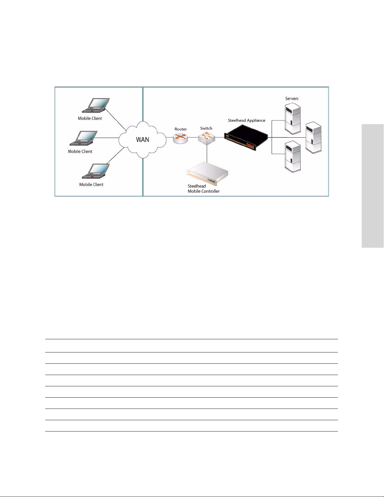
A continuación, se ofrece un ejemplo de una instalación típica de Steelhead Mobile. El Mobile Controller se
ubica en el centro de datos principal. Todos los Mobile Client se comunican con el Mobile Controller para
las actividades de gestión y elaboración de informes. Si posee servidores en varias ubicaciones, deberá
instalar el Steelhead appliance en el lado servidor de los centros de datos o las sucursales.
Figura 2-3. Despliegue típico de Steelhead Mobile
2 INSTALLING AND DEPLOYING STEELHEAD
M
OBILE
Para obtener más información sobre las opciones de despliegue del Steelhead Mobile, consulte la
publicación Steelhead Mobile Controller Installation Guide.
1. Introducción
Lea las notas de la versión del producto en http://www.riverbed.com. Allí encontrará información
importante sobre esta versión del producto.
Compruebe con la lista de empaque si tiene todas las piezas necesarias.
Asegúrese de contar con el espacio necesario en un bastidor de dos o cuatro columnas de 48,26 cm
(19 pulgadas).
Asegúrese de que la temperatura ambiente no supere los 35º C (95º F).
Cerciórese de contar con un destornillador Phillips estándar para instalar el dispositivo en el bastidor.
Tenga a mano los valores para los parámetros que se enumeran en la siguiente lista de comprobación:
Dispositivo Parámetro
Mobile Controller Nombre del host
Dirección IP
Máscara de red
Portal predeterminado (portal WAN)
Servidor DNS principal (dirección IP del servidor de nombres de dominio)
Nombre de dominio
Contraseña del administrador
GETTING STARTED GUIDE 51
Page 52

Mobile Client Tamaño del almacenamiento de datos. Se necesita por lo menos 1 GB de espacio para el
almacenamiento de datos. El valor predeterminado es 10 MB.
NOTA: este valor sólo es necesario si se opta por no usar el paquete MSI predeterminado
(que contiene las políticas predeterminadas de aceleración y de punto final) que viene con el
Steelhead Mobile. En general, los administradores realizan el despliegue del Steelhead
Mobile utilizando los valores predeterminados que se suministran con el producto y los
modifican una vez desplegado el Steelhead Mobile en sus Mobile Client.
Tamaño máximo del registro. El valor predeterminado es 5000 KB.
NOTA: este valor sólo es necesario si se opta por no usar el paquete MSI predeterminado
(que contiene las políticas predeterminadas de aceleración y de punto final) que viene con el
Steelhead Mobile.
Cantidad máxima de archivos de registro. El valor predeterminado es 2.
NOTA: este valor sólo es necesario si se opta por no usar el paquete MSI predeterminado
(que contiene las políticas predeterminadas de aceleración y de punto final) que viene con el
Steelhead Mobile.
Número de puerto VPN. Cuando implementa componentes de Steelhead Mobile tiene que
asegurarse de que el túnel VPN no está optimizado. Si el túnel VPN utiliza TCP para el
transporte, al configurar la política de aceleración, se agrega una regla de paso para el
número del puerto VPN conectado por el cliente. En función del escenario de la
implementación, esta regla puede ser la primera de la lista.
Para obtener detalles sobre las políticas de aceleración, consulte la Steelhead Mobile Controller
User’s Guide.
Las VPN que utilizan IPSec como protocolo de transporte no necesitan una regla de paso.
Esto se debe a que IPSec dispone de su propio protocolo no TCP/IP y, de forma
predeterminada, las aplicaciones de Steelhead no lo optimizan.
Para obtener más información sobre las reglas de atravesar y sobre cómo definirlas, consulte
la publicación Steelhead Mobile Controller User’s Guide
IMPORTANTE: El paquete MSI predeterminado que viene con el Steelhead Mobile es apto para la mayoría de los
entornos de red. En general, Steelhead Mobile se puede instalar y desplegar sin modificar las políticas predeterminadas
que vienen con el producto. Puede desplegar Steelhead Mobile en sus Mobile Client utilizando las políticas
predeterminadas que se suministran y modificarlas sólo si fuera necesario.
Asegúrese de contar con suficiente memoria en los Mobile Client para ejecutar Steelhead Mobile.
Tamaño del
Uso de memoria (MB)
almacenamiento de
datos (GB)
181
2100
5112
10 161
15 171
20 228
52 2 - INSTALLING AND DEPLOYING STEELHEAD MOBILE
Page 53
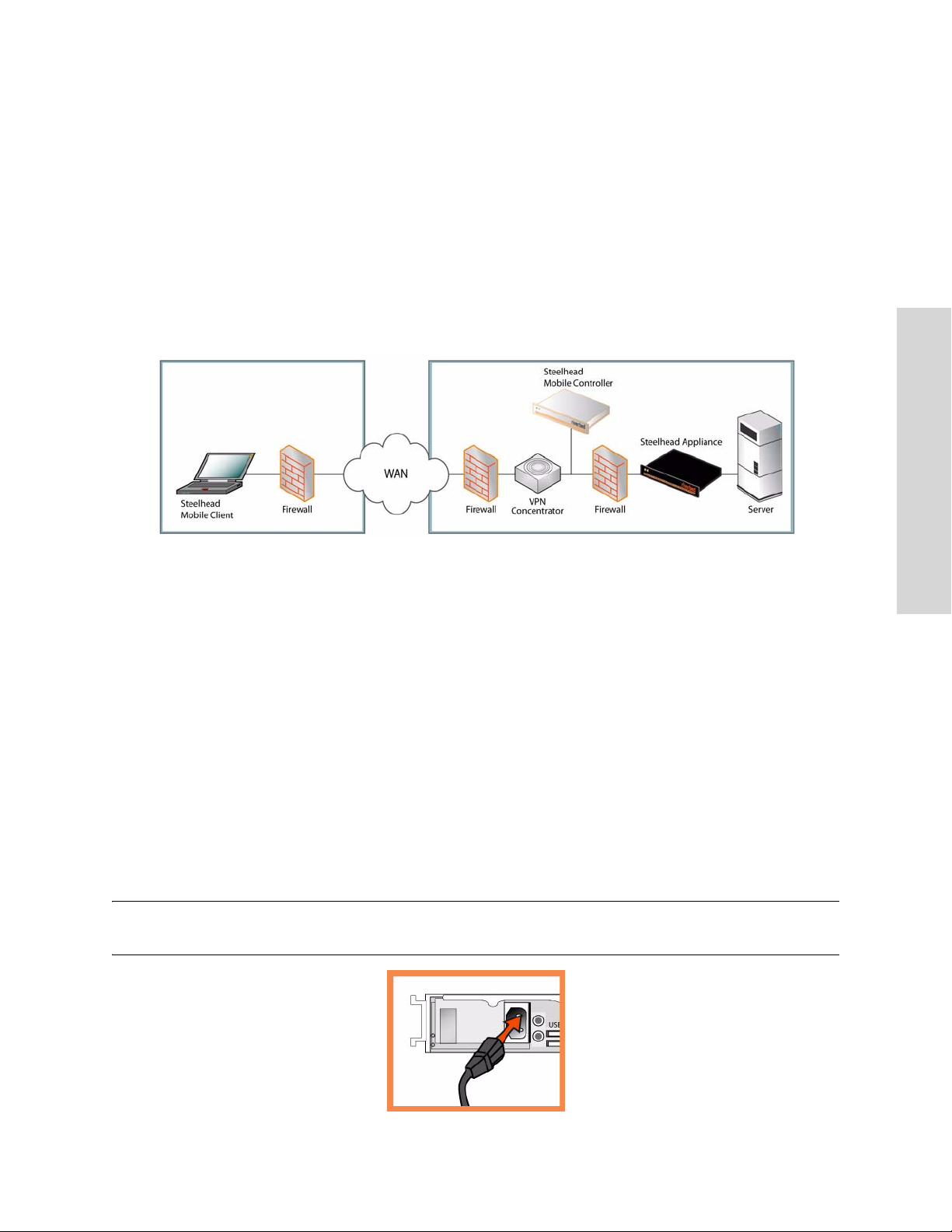
2. Despliegue de Steelhead Mobile en entornos con servidores de seguridad
Si necesita una solución sólo para usuarios con acceso remoto, la ubicación del Controlador móvil debe
estar en el DMZ próximo al concentrador VPN con firewalls a cada lado. Los usuarios que necesiten obtener
acceso al Controlador móvil pueden conectarse a él desde el exterior de la zona DMZ. Este escenario
requiere que el firewall de la red del cliente tenga disponible el puerto 7801. El firewall del servidor debe
tener abiertos los puertos 22, 80, 443, 7800 y 7870.
Si realiza un control de las aplicaciones, tendrá que admitir los archivos rbtdebug.exe, rbtmon.exe,
rbtsport.exe y shmobile.exe.
Figura 2-4. Steelhead Mobile Despliegue en la DMZ
2 INSTALLING AND DEPLOYING STEELHEAD
M
OBILE
3. Instalación en un bastidor
Si su modelo viene con un bisel, retírelo.
Alinee los orificios para tornillos de las bridas con sus pares en el bastidor.
Inserte los tornillos ubicados a ambos lados del dispositivo y ajústelos firmemente.
4. Conexión de la fuente de alimentación
Si su modelo cuenta con un interruptor de encendido maestro, asegúrese de que esté en la posición de
apagado (en el panel posterior).
Enchufe el o los cables de alimentación en el Mobile Controller y en un tomacorriente de CA.
Si su modelo cuenta con un interruptor de encendido maestro, presiónelo (posición ENCENDIDO).
Presione el interruptor de encendido del sistema situado en la parte frontal del Mobile Controller.
PRECAUCIÓN: En todos los entornos eléctricos europeos, deberá conectar a tierra la lengüeta verde o amarilla del
cable de alimentación. De lo contrario, se podría producir un choque eléctrico.
GETTING STARTED GUIDE 53
Page 54
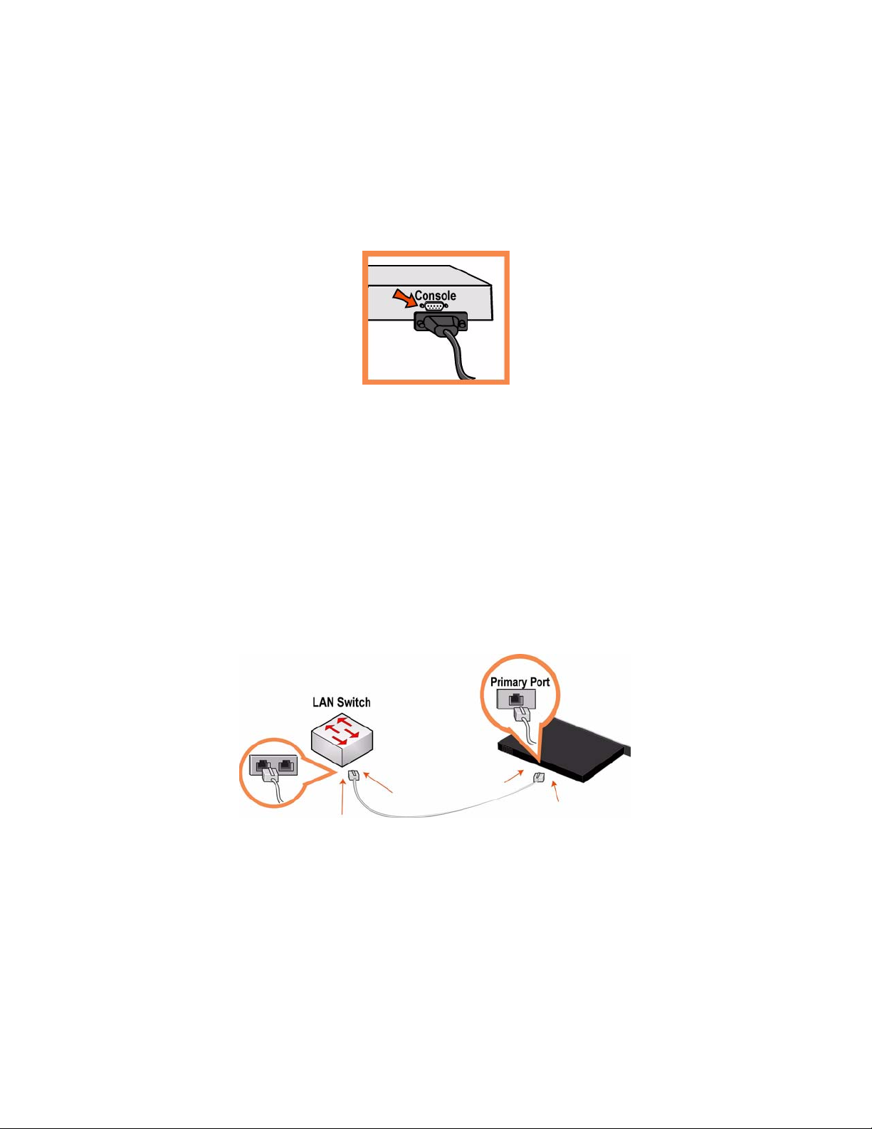
5. Conexión con el Mobile Controller
Enchufe el cable serial en el puerto de la consola y en una terminal.
Asegúrese de que los ajustes del puerto de la consola sean los siguientes: 9600, 8 bits de datos, sin
paridad, un bit de parada, sin control de flujo.
Inicie el programa de emulación de terminal (por ejemplo, HyperTerminal o Tera Term Pro).
En el indicador de inicio de sesión, escriba admin. La contraseña predeterminada es password.
6. Configuración de Mobile Controller
El asistente de configuración se inicia automáticamente cuando usted inicia la sesión en la interfaz de
línea de comando por primera vez.
Siga las indicaciones que aparecen en pantalla para configurar los parámetros de red y de la interfaz en
ruta para el Mobile Controller.
Confirme los valores, y escriba exit para desconectarse del sistema.
7. Conexión de Mobile Controller a la red
Enchufe el cable de conexión en el puerto principal del Mobile Controller y en el conmutador de LAN.
Puede ser cualquier puerto del conmutador LAN configurado para conectarse con el host.
Controle los indicadores luminosos de estado para verificar que el dispositivo está correctamente
conectado.
54 2 - INSTALLING AND DEPLOYING STEELHEAD MOBILE
Page 55

8. Inicio de sesión en el Mobile Controller
Escriba el URL del Mobile Controller en el cuadro de dirección del explorador de Internet:
http://host.domain o https://host.domain
Aparece el Mobile Controller y muestra la página de bienvenida.
En el cuadro de texto Account (Cuenta), escriba admin.
En el cuadro de texto Password (Contraseña), escriba la contraseña que le asignaron.
Haga clic en Login (Iniciar sesión) para abrir la página de inicio.
9. Pasos siguientes
Steelhead Mobile ha sido diseñado para desplegar en los Mobile Client sin que sea necesario realizar
ninguna configuración. El producto viene con políticas de aceleración y punto final predeterminadas con
los valores predeterminados para el paquete MSI que se despliega en los Mobile Client de su red.
En general, el Steelhead Mobile se puede instalar y desplegar sin modificar las políticas predeterminadas
que vienen con el producto. Puede desplegar el Steelhead Mobile en sus Mobile Client utilizando las
políticas predeterminadas que se suministran y modificarlas sólo si fuera necesario.
2 INSTALLING AND DEPLOYING STEELHEAD
M
OBILE
Si ha optado por usar el paquete MSI predeterminado, en la página Manage Endpoints – Packages
(Gestionar punto final - paquetes), haga clic en el URL del paquete MSI predeterminado y guárdelo en
la máquina local.
Utilice una herramienta de despliegue de su elección (Microsoft SMS, por ejemplo) para instalar el
paquete MSI predeterminado en los Mobile Client de la red.
Compruebe las conexiones y la optimización de los Mobile Client en el informe Managed Endpoints
(Puntos finales gestionados) de Mobile Controller.
NOTA: Puede modificar las políticas de punto final y de aceleración predeterminadas que conforman el paquete MSI
predeterminado. Para obtener información sobre la modificación de las políticas predeterminadas, consulte la
publicación Steelhead Mobile Controller User’s Guide
Installation und Bereitstellung von Steelhead Mobile
In diesem Abschnitt wird die schnelle Installation, Konfiguration und Bereitstellung von Steelhead Mobile
beschrieben. Weitere Informationen finden Sie auf der Documentation Set CD.
Übersicht
Steelhead Mobile ermöglicht das Optimieren des TCP-Verkehrs für Remotebenutzer, die auf das Netzwerk
zugreifen (z.B. über eine DFÜ-, Broadband- oder Drahtlosverbindung). Die Steelhead Mobile Bereitstellung
umfasst folgende Komponenten: Mobile Controller, Mobile Client und Steelhead appliance.
GETTING STARTED GUIDE 55
Page 56
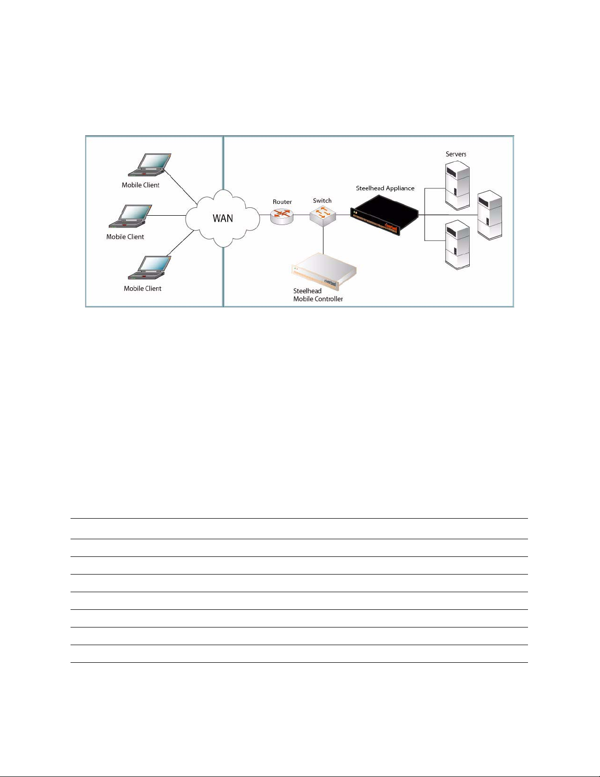
Im Folgenden finden Sie ein Beispiel einer typischen Steelhead Mobile Installation. Der Mobile Controller
befindet sich im Hauptdatencenter. Alle Mobile Clients kommunizieren zu Verwaltungs- und
Berichtszwecken mit dem Mobile Controller. Wenn sich die Server an verschiedenen Standorten befinden,
installieren Sie die Steelhead appliancee in den Datencentern oder Niederlassungen.
Abbildung 2-5. Typische Steelhead Mobile Bereitstellung
Weitere Informationen zu den Steelhead Mobile Bereitstellungsoptionen finden Sie im Steelhead Mobile
Controller Installation Guide.
1. Erste Schritte
Lesen Sie die Produkthinweise unter http://www.riverbed.com, die wichtige Informationen zu dieser
Version enthalten.
Überprüfen Sie den Packzettel, um sicherzustellen, dass alle erforderlichen Teile vorhanden sind.
Stellen Sie sicher, dass genügend Platz auf einem 19-Zoll-Rack mit zwei oder vier Säulen vorhanden ist.
Stellen Sie sicher, dass die Raumtemperatur nicht höher als 35 ºC (95 ºF) ist.
Zum Montieren des Geräts in einem Rack benötigen Sie einen Kreuzschlitzschraubenzieher.
Für die in folgender Prüfliste aufgeführten Parameter benötigen Sie die entsprechenden Werte:
Gerät Parameter
Mobile Controller Hostname
IP-Adresse
Netzmaske
Standardgateway (WAN-Gateway)
Primärer DNS0-Server (IP-Adresse des Domänennamenservers)
Domänenname
Administratorkennwort
56 2 - INSTALLING AND DEPLOYING STEELHEAD MOBILE
Page 57

Mobile Client Größe des Datenspeichers. Für den Datenspeicher ist mindestens 1 GB Speicherplatz
erforderlich. Der Standardwert beträgt 10 MB.
HINWEIS: Sie benötigen diesen Wert nur, wenn Sie das MSI-Standardpaket
(Standardrichtlinien für Beschleunigung und Endpunkt) nicht verwenden, das in Steelhead
Mobile enthalten ist. Administratoren stellen Steelhead Mobile normalerweise mit den
Standardwerten bereit und ändern diese, nachdem Steelhead Mobile auf den Mobile Clients
bereitgestellt wurde.
Maximale Protokollgröße. Der Standardwert beträgt 5000 KB.
HINWEIS: Sie benötigen diesen Wert nur, wenn Sie das MSI-Standardpaket
(Standardrichtlinien für Beschleunigung und Endpunkt) nicht verwenden, das in Steelhead
Mobile enthalten ist.
Maximale Anzahl der Protokolldateien. Der Standardwert beträgt 2.
HINWEIS: Sie benötigen diesen Wert nur, wenn Sie das MSI-Standardpaket
(Standardrichtlinien für Beschleunigung und Endpunkt) nicht verwenden, das in Steelhead
Mobile enthalten ist.
VPN-Portnummer. Stellen Sie vor der Bereitstellung von Steelhead Mobile-Komponenten
sicher, dass der VPN-Tunnel nicht optimiert ist. Wenn der VPN-Tunnel für den Transport
TCP verwendet, fügen Sie in der Beschleunigungsrichtlinie eine Übergaberegel für die
VPN-Portnummer der Clientverbindung hinzu. Abhängig von der Bereitstellung, ist diese
Regel möglicherweise die erste Regel in der Liste.
Weitere Informationen zu Beschleunigungsrichtlinien finden Sie im Steelhead Mobile
Controller User’s Guide.
VPNs, die IPSec als Transportprotokoll verwenden, erfordern keine Übergaberegel, da
IPSec kein TCP/IP-Protokoll ist und standardmäßig von den Steelhead-Geräten nicht
optimiert wird.
Weitere Informationen zu Übergaberegeln und deren Konfiguration finden Sie im Steelhead
Mobile Controller User’s Guide
2 INSTALLING AND DEPLOYING STEELHEAD
M
OBILE
WICHTIG: Das MSI-Standardpaket, das in Steelhead Mobile enthalten ist, ist für die meisten Netzwerkumgebungen
geeignet. Steelhead Mobile kann normalerweise installiert werden, ohne dass die Standardrichtlinien geändert werden
müssen. Stellen Sie Steelhead Mobile auf Ihren Mobile Clients unter Verwendung der Standardrichtlinien bereit und
ändern Sie diese nur, falls dies erforderlich ist.
Stellen Sie sicher, dass genügend Speicher auf den Mobile Clients vorhanden ist, um Steelhead Mobile
auszuführen.
Größe des
Datenspeichers (GB)
181
2100
5112
10 161
15 171
20 228
Arbeitsspeicher (MB)
GETTING STARTED GUIDE 57
Page 58
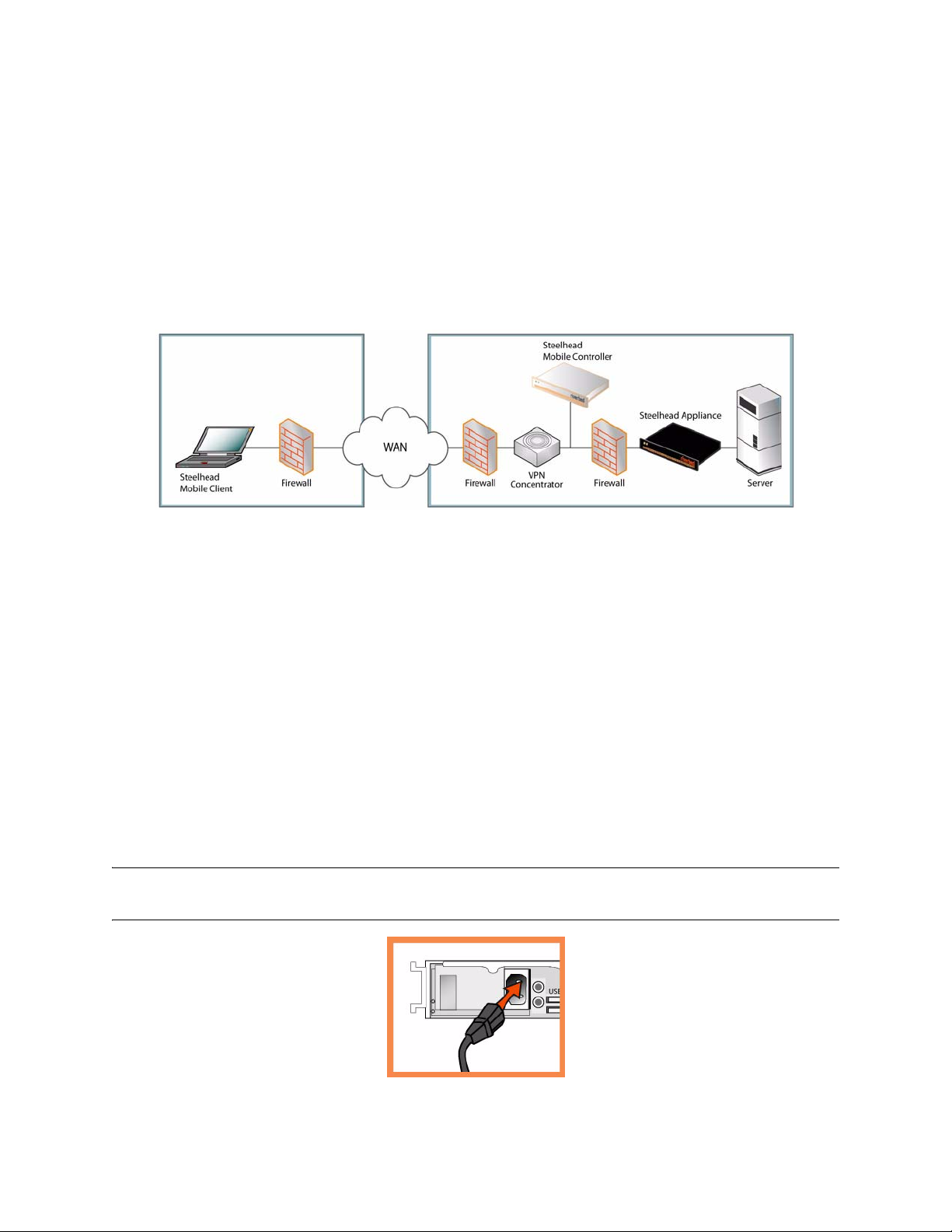
2. Bereitstellung von Steelhead Mobile in Umgebungen mit Firewalls
Wenn Sie nur für Remotebenutzer eine Lösung benötigen, können Sie den Mobile Controller im
Umkreisnetzwerk neben einem VPN-Konzentrator mit Firewalls an beiden Seiten positionieren. Die
Benutzer können von außerhalb des Umkreisnetzwerks auf den Mobile Controller zugreifen. Dieses
Szenario erfordert, dass Port 7801 auf der clientseitigen Netzwerkfirewall verfügbar ist. Auf der
serverseitigen Firewall müssen die Ports 22, 80, 443, 7800 und 7870 offen sein.
Wenn Sie die Anwendungssteuerung verwenden, müssen Sie rbtdebug.exe, rbtmon.exe, rbtsport.exe und
shmobile.exe zulassen.
Abbildung 2-6. Steelhead Mobile Bereitstellung im Umkreisnetzwerk
3. Montage in einem Rack
Wenn das Modell mit einer Blende versehen ist, entfernen Sie diese.
Richten Sie die Befestigungslöcher an den Kanten mit den Befestigungslöchern im Rack aus.
Setzen Sie die Schrauben an den Seiten des Geräts ein und ziehen Sie diese an.
4. Stromanschluss
Wenn Ihr Modell mit einem Hauptstromschalter ausgestattet ist (an der Rückseite), stellen Sie sicher,
dass dieser ausgeschaltet ist.
Stecken Sie das Stromkabel in den Mobile Controller und in eine Steckdose ein.
Wenn Ihr Modell mit einem Hauptstromschalter ausgestattet ist, schalten Sie diesen ein.
Drücken Sie den Systemstromschalter an der Vorderseite des Mobile Controllers.
ACHTUNG: In allen europäischen Ländern muss die grün-gelbe Klemme über das Stromkabel geerdet werden.
Ansonsten kann ein elektrischer Stromschlag verursacht werden.
58 2 - INSTALLING AND DEPLOYING STEELHEAD MOBILE
Page 59
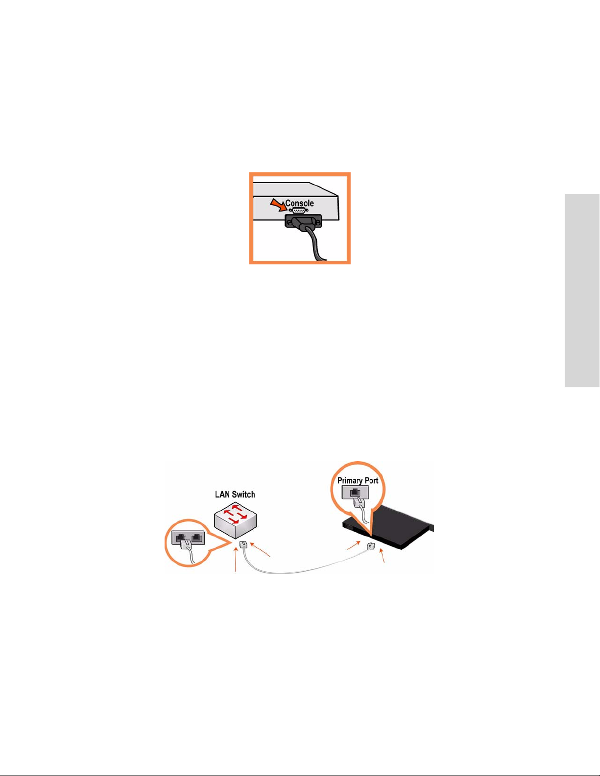
5. Verbinden mit Mobile Controller
Stecken Sie das serielle Kabel in den Konsolenanschluss und ein Terminal ein.
Überprüfen Sie die Einstellungen für den Konsolenanschluss: 9600 Bit/s, 8 Datenbits, keine Parität,
1 Stoppbit, keine Flusssteuerung.
Starten Sie das Terminalemulationsprogramm (z.B. HyperTerminal oder Tera Term Pro).
Geben Sie an der Anmeldeaufforderung admin ein. Das Standardkennwort ist password..
6. Konfigurieren des Mobile Controllers
Der Konfigurations-Assistent wird automatisch gestartet, wenn Sie sich das erste Mal über die
Befehlszeile anmelden.
2 INSTALLING AND DEPLOYING STEELHEAD
M
OBILE
Folgen Sie den Anweisungen, um das Netzwerk und die integrierten Schnittstelleneinstellungen für
den Mobile Controller zu konfigurieren.
Bestätigen Sie die Einstellungen und geben Sie anschließend exit ein, um sich abzumelden.
7. Verbinden des Mobile Controllers mit dem Netzwerk
Stecken Sie ein Durchgangskabel in den primären Port von Mobile Controller und des LAN-Switches
ein. Hierbei kann es sich um einen beliebigen Port auf dem LAN-Switch handeln, der für die
Verbindung mit einem Host konfiguriert ist.
Überprüfen Sie die LED-Statusanzeigen, um sicherzustellen, dass das Gerät richtig angeschlossen ist.
GETTING STARTED GUIDE 59
Page 60

8. Anmelden am Mobile Controller
Geben Sie die URL für den Mobile Controller in die Adresszeile des Webbrowsers ein:
http://host.domain oder https://host.domain
Die Willkommensseite des Mobile Controllers wird angezeigt.
Geben Sie admin im Textfeld Konto ein.
Geben Sie im Textfeld Kennwort Ihr Kennwort ein.
Klicken Sie auf Anmelden, um die Startseite anzuzeigen.
9. Nächste Schritte
Steelhead Mobile kann ohne weitere Konfiguration auf den Mobile Clients bereitgestellt werden. Die
enthaltenen Standardrichtlinien für Beschleunigung und Endpunkt umfassen die Standardwerte für das
MSI-Paket, das auf den Mobile Clients im Netzwerk bereitgestellt wird.
Steelhead Mobile kann normalerweise installiert werden, ohne dass die Standardrichtlinien geändert
werden müssen. Stellen Sie Steelhead Mobile auf Ihren Mobile Clients unter Verwendung der
Standardrichtlinien bereit und ändern Sie diese nur, falls dies erforderlich ist.
Wenn Sie das MSI-Standardpaket verwenden (Seite Endpunkte – Pakete verwalten), klicken Sie auf die
URL für das MSI-Standardpaket und speichern Sie diese auf Ihrem Computer.
Sie können das MSI-Standardpaket mit einem beliebigen Tool (z.B. Microsoft SMS) auf den Mobile
Clients im Netzwerk bereitstellen.
Stellen Sie in den verwalteten Endpunkten sicher, dass die Mobile Client Verbindungen und
Optimierung mit dem Mobile Controller kommunizieren.
HINWEIS: Sie können die Standardrichtlinien für Beschleunigung und Endpunkt des MSI-Pakets ändern. Weitere
Informationen zum Ändern der Standardrichtlinien finden Sie im Steelhead Mobile Controller User’s Guide.
Installation et déploiement de Steelhead Mobile
Cette section décrit comment installer, configurer et déployer rapidement Steelhead Mobile. Pour plus de
détails, reportez-vous à la Documentation Set CD.
Généralités
Steelhead Mobile vous permet d’optimiser le trafic TCP vers les utilisateurs distants qui accèdent à votre
réseau à l’aide d’une connexion à distance quelconque (par exemple, par le biais d’une connexion à
numérotation, à haut débit ou sans fil). Le déploiement de Steelhead Mobile fait intervenir les composants
suivants : le Mobile Controller, le Mobile Client et l'Steelhead appliance.
60 2 - INSTALLING AND DEPLOYING STEELHEAD MOBILE
Page 61
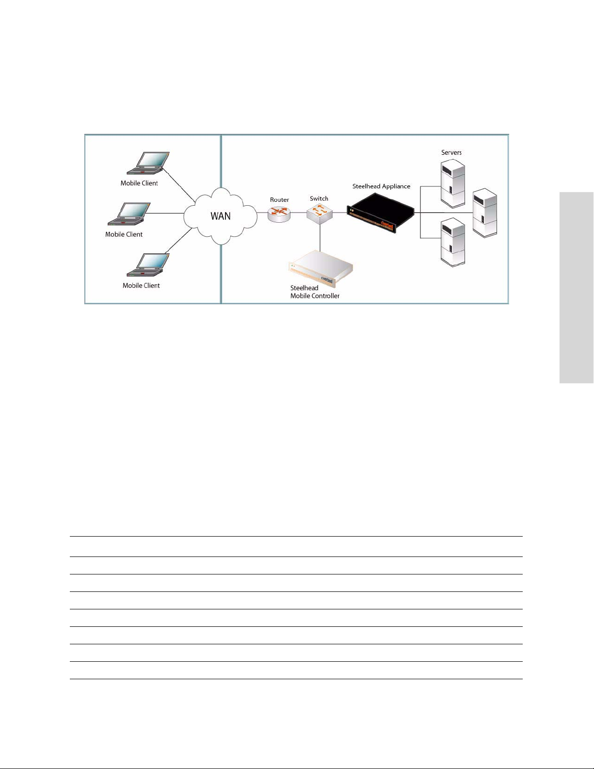
Voici un exemple d’installation typique de Steelhead Mobile. Le Mobile Controller réside dans le centre de
données principal. Chaque Mobile Client communique avec le Mobile Controller pour la gestion et la
création de rapports. Si vous disposez de serveurs situés à plusieurs endroits, vous devez installer le
Steelhead appliance côté serveur dans les centres de données ou dans les succursales.
Figure 2-7. Déploiement typique de Steelhead Mobile
2 INSTALLING AND DEPLOYING STEELHEAD
M
OBILE
Pour plus de détails sur les options de déploiement de Steelhead Mobile, reportez-vous au Steelhead Mobile
Controller Installation Guide.
1. Mise en route
Veuillez lire les notes de mise à jour relatives au produit, publiées sur le site http://www.riverbed.com. Elles
contiennent d'importantes informations sur cette version.
Vérifiez sur votre bon de livraison que toutes les pièces nécessaires vous ont bien été livrées.
Vérifiez que vous disposez d'un espace suffisant pour installer l'appareil sur un support de 50 cm
(19 po) à deux ou quatre montants.
Assurez-vous que la température ambiante ne dépasse pas 35º C (95º F).
Vous devrez utiliser un tournevis à empreinte cruciforme standard pour monter l'appareil sur un
support.
Veuillez avoir à votre disposition les valeurs des paramètres suivants :
Appareil Paramètre
Mobile Controller Nom d’hôte
Adresse IP
Masque de sous-réseau
Passerelle par défaut (la passerelle WAN)
Serveur DNS principal (adresse IP du serveur de noms de domaines)
Nom de domaine
Mot de passe de l’administrateur
GETTING STARTED GUIDE 61
Page 62

Mobile Client Taille de la banque de données. Au moins 1 Go d’espace disque est requis pour la banque
de données. La valeur par défaut est 10 Mo.
REMARQUE : Vous ne devrez utiliser cette valeur que si vous choisissez de ne pas utiliser
le package MSI par défaut (qui contient les stratégies par défaut de point de fin et
d’accélération) livré avec Steelhead Mobile. En général, les administrateurs déploient
Steelhead Mobile en utilisant les valeurs par défaut définies en usine et modifient ces
dernières après avoir déployé Steelhead Mobile sur leurs Mobile Clients.
Taille maximale du journal. La valeur par défaut est 5 000 Ko.
REMARQUE : Vous ne devrez utiliser cette valeur que si vous choisissez de ne pas utiliser
le package MSI par défaut (qui contient les stratégies par défaut de point de fin et
d’accélération) livré avec Steelhead Mobile.
Nombre maximal de fichiers journaux. La valeur par défaut est 2.
REMARQUE : Vous ne devrez utiliser cette valeur que si vous choisissez de ne pas utiliser
le package MSI par défaut (qui contient les stratégies par défaut de point de fin et
d’accélération) livré avec Steelhead Mobile.
Numéro de port VPN. Lorsque vous déployez des composants Steelhead Mobile, vous
devez vous assurer que le tunnel VPN n'est pas optimisé. Si le tunnel VPN utilise TCP pour
le transport, lors de la configuration de la stratégie d'accélération, ajoutez une règle de
transfert pour le numéro du port VPN qui a été connecté par le client. Selon votre scénario
de déploiement, cette règle pourra être la première de la liste.
Pour plus de détails sur les stratégies d'accéleration, voir le Steelhead Mobile Controller User’s
Guide.
Les réseaux VPN qui utilisent IPSec comme protocole de transport ne nécessitent pas de
règle de transfert. En effet, IPSec étant lui-même son propre protocole non TCP/IP, par
défaut, les appareils Steelhead ne l'optimisent pas.
Pour plus de détails sur les règles de transfert et leur configuration, reportez-vous au
Steelhead Mobile Controller User’s Guide
IMPORTANT : Le package MSI par défaut livré avec Steelhead Mobile est conçu pour être compatible avec la plupart
des environnements réseau. En général, vous pouvez installer et déployer Steelhead Mobile sans modifier les stratégies
par défaut livrées avec le produit. Il est conseillé de déployer Steelhead Mobile sur vos clients mobiles en utilisant les
stratégies par défaut fournies, et de ne modifier celles-ci qu'en cas de nécessité absolue.
Assurez-vous que la mémoire de vos Mobile Clients est suffisante pour exécuter Steelhead Mobile.
Taille de la banque de
données (Go)
Utilisation de la
mémoire (Mo)
181
2100
5112
10 161
15 171
20 228
62 2 - INSTALLING AND DEPLOYING STEELHEAD MOBILE
Page 63
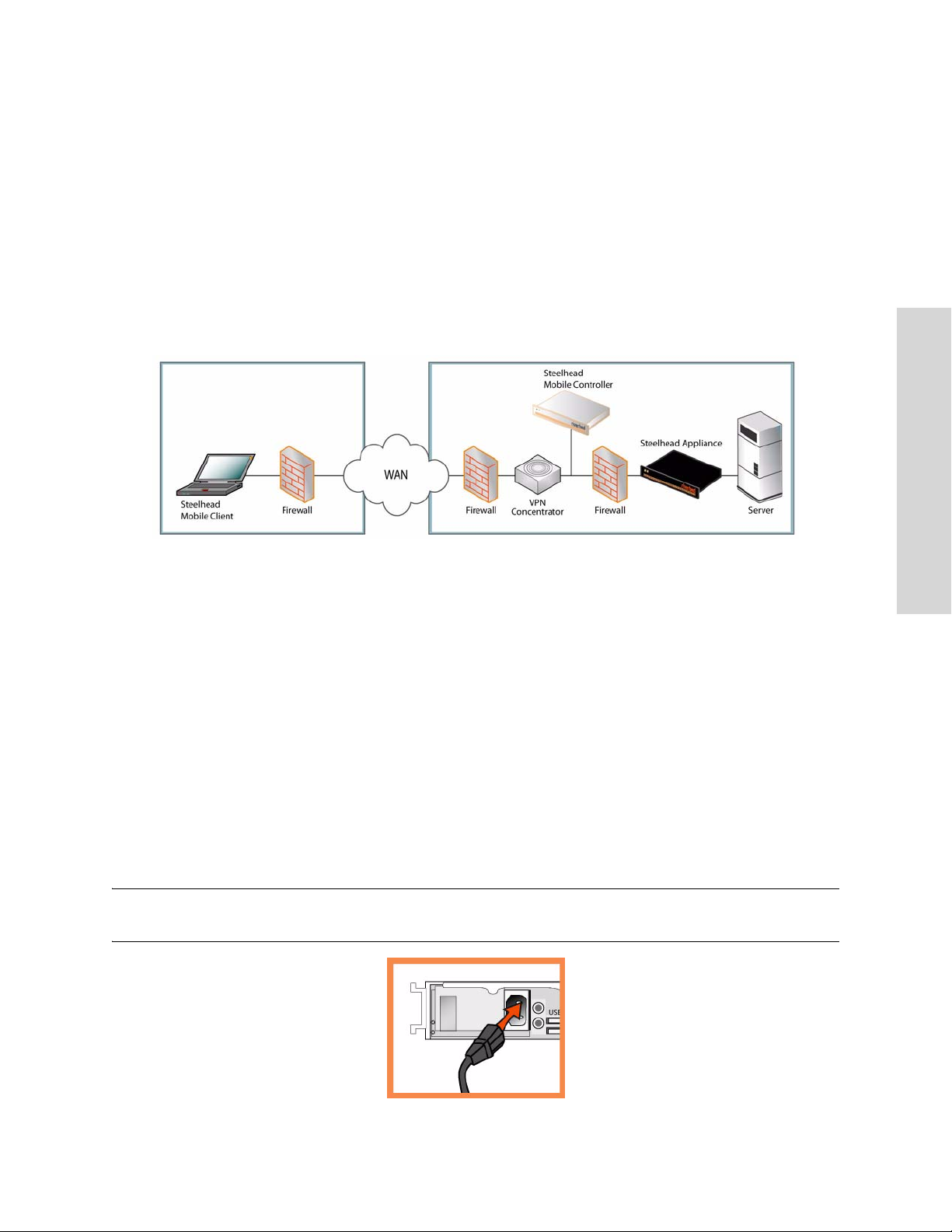
2. Déploiement de Steelhead Mobile dans des environnements protégés par des pare-feu
Si vous avez besoin d'une solution uniquement pour les utilisateurs de l'accès distant, vous pouvez placer
le Contrôleur Mobile dans une zone démilitarisée (DMZ) située près d'un concentrateur VPN, avec des
pare-feu de chaque côté. Les utilisateurs qui doivent accéder au Contrôleur Mobile peuvent s'y connecter
en dehors de la zone démilitarisée. Ce scénario nécessite que le port 7801 soit disponible sur le pare-feu du
réseau côté client. Les ports 22, 80, 443, 7800 et 7870 doivent être ouverts sur le pare-feu côté serveur.
Si vous utilisez le contrôle d'applications, vous devez activer rbtdebug.exe, rbtmon.exe, rbtsport.exe et
shmobile.exe.
Figure 2-8. Steelhead Mobile Déploiement dans la zone démilitarisée (DMZ)
2 INSTALLING AND DEPLOYING STEELHEAD
M
OBILE
3. Montage sur un support
Si votre appareil est doté d'un cadre, veuillez le retirer.
Alignez les trous de vis des brides aux trous de vis du support.
Insérez les vis sur chaque côté de l'appareil et serrez-les.
4. Branchement sur secteur
Si votre appareil est équipé d’un interrupteur d'alimentation principal, vérifiez que celui-ci est en
position Arrêt (sur le panneau arrière).
Branchez le(s) cordon(s) d'alimentation dans le Mobile Controller et dans une prise de courant.
Si votre appareil est équipé d’un interrupteur d'alimentation principal, appuyez dessus (ON).
Appuyez sur l’interrupteur d'alimentation système situé à l’avant du Mobile Controller.
ATTENTION : Dans toutes les installations électriques en Europe, la fiche jaune/verte du cordon d'alimentation doit
être mise à la terre. Si la fiche jaune/verte n'est pas mise à la terre, il y a un risque de choc électrique.
GETTING STARTED GUIDE 63
Page 64
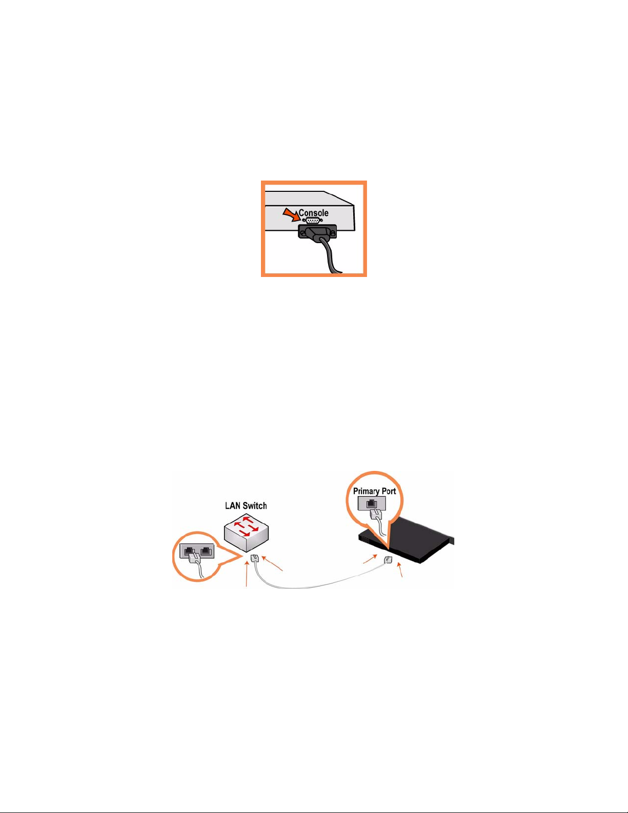
5. Connexion au Mobile Controller
Branchez le câble série dans le port Console et à un terminal.
Vérifiez que les paramètres du port Console sont bien les suivants : 9600, 8 bits de données, sans parité,
1 bit d'arrêt, pas de contrôle de flux.
Lancez votre programme d'émulation de terminal (par exemple, HyperTerminal ou Tera Term Pro).
À l'invite, entrez admin. Le mot de passe par défaut est password.
6. Configuration du Mobile Controller
L'assistant de configuration est automatiquement lancé à la première ouverture de session de
l'interface de ligne de commande.
Suivez les invites pour configurer le réseau et les paramètres de l'interface interne du Mobile
Controller.
Confirmez vos paramètres, puis tapez exit pour quitter le système.
7. Connexion du Mobile Controller à votre réseau
Branchez le câble droit dans le port principal du Mobile Controller et dans l'interrupteur LAN. Il peut
s'agir de tout port de votre interrupteur LAN configuré pour la connexion à un hôte.
Pour vous assurer que l'appareil est bien branché, vérifiez que la DEL d'état s'allume.
64 2 - INSTALLING AND DEPLOYING STEELHEAD MOBILE
Page 65

8. Connexion au Mobile Controller
Entrez l'URL du Mobile Controller dans la zone d'adresse de votre navigateur Web :
http://host.domain ou https://host.domain
Le Mobile Controller apparaît, et la page de bienvenue s'affiche.
Dans la zone de texte dédiée au compte, tapez admin.
Dans la zone de texte réservée au mot de passe, tapez votre mot de passe.
Cliquez sur Login (Ouvrir une session) pour afficher la page d'accueil.
9. Étapes suivantes
Steelhead Mobile est conçu pour être déployé sur vos Mobile Clients sans qu'une configuration
additionnelle ne soit nécessaire. Le produit est livré avec des stratégies par défaut de point de fin et
d’accélération, qui fournissent les valeurs par défaut du package MSI déployé sur les Mobile Clients de
votre réseau.
En général, vous pouvez installer et déployer Steelhead Mobile sans modifier les stratégies par défaut
livrées avec le produit. Il est conseillé de déployer Steelhead Mobile sur vos clients mobiles en utilisant les
stratégies par défaut fournies, et de ne modifier celles-ci qu'en cas de nécessité absolue.
2 INSTALLING AND DEPLOYING STEELHEAD
M
OBILE
Si vous avez décidé d’utiliser le package MSI par défaut, allez à la page Manage Endpoints – Packages
(Administration des points de fin – Packages), cliquez sur l’URL correspondant au package MSI par
défaut et téléchargez ce dernier sur votre ordinateur local.
À l’aide de l’outil de déploiement de votre choix (par exemple, Microsoft SMS), déployez le package
MSI par défaut sur les Mobile Clients de votre réseau.
Vérifiez les connexions et l’optimisation du Mobile Client dans le rapport Managed Endpoints (Points
de fin gérés) du contrôleur mobile.
REMARQUE : Vous pouvez modifier les stratégies par défaut de point de fin et d’accélération qui constituent le
package MSI par défaut. Pour plus de détails sur la modification des stratégies par défaut, reportez-vous au Steelhead
Mobile Controller User’s Guide.
Installazione e distribuzione di Steelhead Mobile
In questa sezione viene descritto come installare, configurare e distribuire Steelhead Mobile. Per ulteriori
informazioni, consultare il Documentation Set CD.
Panoramica
Steelhead Mobile consente di ottimizzare il traffico TCP verso utenti che accedono alla rete mediante
accesso remoto, tra cui connessione remota, a banda larga e wireless. La distribuzione di Steelhead Mobile
include i seguenti componenti: il Mobile Controller, il Mobile Client e l'Steelhead appliance.
GETTING STARTED GUIDE 65
Page 66
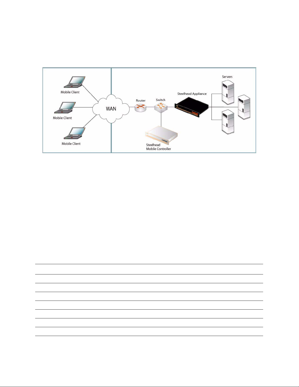
Di seguito è descritta una tipica installazione di Steelhead Mobile. Il Mobile Controller si trova nel centro
dati principale e comunica con tutti i Mobile Client a scopo di gestione e generazione di rapporti. Se sono
presenti più server dislocati in diverse sedi, installare apparecchiature Steelhead sul lato server presso i
centri dati o le filiali interessate.
Figura 2-9. Distribuzione tipica di Steelhead Mobile
Per informazioni su altre opzioni di distribuzione di Steelhead Mobile, consultare la Steelhead Mobile
Controller Installation Guide.
1. Operazioni preliminari
Leggere le note sulla versione del prodotto disponibili all'indirizzo http://www.riverbed.com che
contengono informazioni importanti relative a questa versione specifica.
Verificare che nella confezione siano presenti tutti i componenti necessari.
Assicurarsi di disporre di spazio sufficiente in un rack da 19 pollici a due o quattro montanti.
Assicurarsi che la temperatura ambiente non superi 35 ºC.
Assicurarsi di disporre di un cacciavite a croce standard da utilizzare per l'installazione
dell'apparecchiatura nel rack.
Assicurarsi di disporre dei valori per l'impostazione dei parametri elencati nella seguente tabella.
Apparecchiatura Parametro
Controller Mobile Nome host
Indirizzo IP
Maschera di rete
Gateway predefinito (gateway WAN)
Server DNS primario (indirizzo IP del server dei nomi di dominio)
Nome di dominio
Password dell'amministratore
66 2 - INSTALLING AND DEPLOYING STEELHEAD MOBILE
Page 67

Client Mobile Dimensione dell'archivio dati. Per l'archiviazione dei dati deve essere disponibile almeno
uno spazio di 1 GB. Il valore predefinito è 10 MB.
NOTA: impostare questo valore solo se si decide di non utilizzare il pacchetto MSI
predefinito fornito con Steelhead Mobile, che contiene i criteri predefiniti per gli endpoint e
l'accelerazione. In genere gli amministratori utilizzano i valori predefiniti forniti con il
prodotto per l'installazione di Steelhead Mobile e li modificano dopo avere distribuito
Steelhead Mobile sui Mobile Client.
Dimensione massima del registro. Il valore predefinito è 5000 KB.
NOTA: impostare questo valore solo se si decide di non utilizzare il pacchetto MSI
predefinito fornito con Steelhead Mobile, che contiene i criteri predefiniti per gli endpoint e
l'accelerazione.
Numero massimo di file di registro. Il valore predefinito è 2.
NOTA: impostare questo valore solo se si decide di non utilizzare il pacchetto MSI
predefinito fornito con Steelhead Mobile, che contiene i criteri predefiniti per gli endpoint e
l'accelerazione.
Numero della porta VPN. Quando si distribuiscono componenti di Steelhead Mobile,
assicurarsi che il tunnel VPN non sia ottimizzato. Se il tunnel VPN utilizza il protocollo TCP
per la trasmissione, quando si configura il criterio di accelerazione, aggiungere una regola
di attraversamento per il numero della porta VPN a cui il client si connette. A seconda dello
scenario di distribuzione, questa regola potrebbe essere la prima nell'elenco.
Per informazioni sui criteri di accelerazione, consultare la Steelhead Mobile Controller User’s
Guide.
Per i tunnel VPN che utilizzano IPSec come protocollo di trasmissione non è necessario
definire una regola di attraversamento perché IPSec è un protocollo non TCP/IP che per
impostazione predefinita non viene ottimizzato dalle apparecchiature Steelhead.
Per informazioni sulle regole di attraversamento e la loro impostazione, consultare la
Steelhead Mobile Controller User’s Guide
2 INSTALLING AND DEPLOYING STEELHEAD
M
OBILE
IMPORTANTE: il pacchetto MSI predefinito fornito con Steelhead Mobile è compatibile con la maggior parte degli
ambienti di rete. In genere è possibile installare e distribuire Steelhead Mobile senza dovere modificare i criteri
predefiniti forniti con il prodotto. Si consiglia quindi di distribuire Steelhead Mobile sui client Mobile utilizzando i
criteri predefiniti e modificarli solo se necessario.
Assicurarsi di disporre sul Mobile Client di una quantità sufficiente di memoria per eseguire Steelhead
Mobile.
Dimensione
dell'archivio dati (GB)
181
2100
5112
10 161
15 171
20 228
Utilizzo della
memoria (MB)
GETTING STARTED GUIDE 67
Page 68
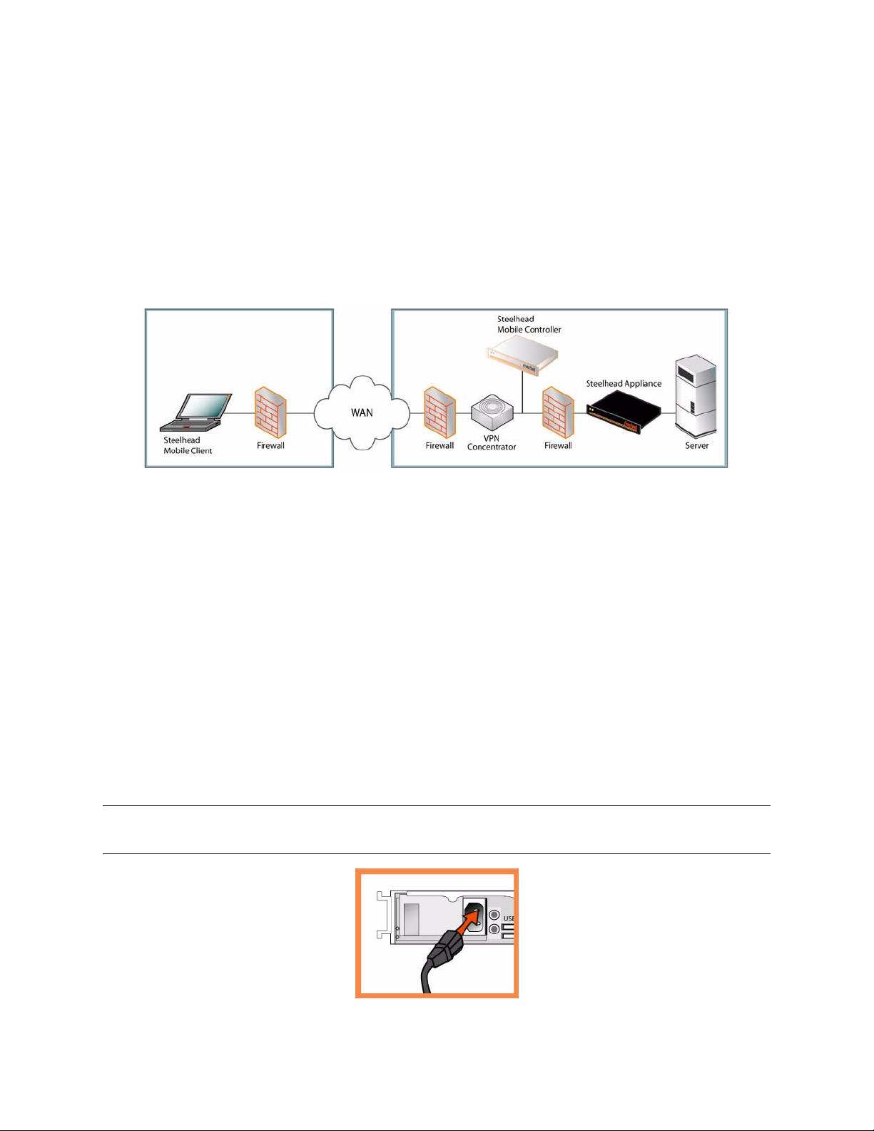
2. Distribuzione di Steelhead Mobile in ambienti con firewall
Se è necessario consentire l'accesso solo a utenti remoti, è possibile posizionare il controller Mobile nella
zona DMZ accanto al concentratore VPN con firewall a entrambi i lati. Gli utenti che devono accedere al
controller Mobile possono connettersi dal di fuori della zona DMZ. In questo scenario sul firewall della rete
lato client deve essere disponibile la porta 7801 mentre sul firewall della rete lato server devono essere
aperte le porte 22, 80, 443, 7800 e 7870.
Se si desidera utilizzare il controllo delle applicazioni, è necessario consentire l'esecuzione di rbtdebug.exe,
rbtmon.exe, rbtsport.exe e shmobile.exe.
Figura 2-10. Distribuzione di Steelhead Mobile in una zona DMZ
3. Installazione nel rack
Se il modello è dotato di frontalino, rimuoverlo.
Allineare i fori delle viti sulle flangie con quelli sul rack.
Inserire e serrare le viti su entrambi i lati dell'apparecchiatura.
4. Collegamento dell'alimentazione
Se il modello è dotato di interruttore di alimentazione principale, sul pannello posteriore, verificare che
sia nella posizione off.
Collegare il cavo o i cavi di alimentazione al Mobile Controller e alla presa di corrente CA.
Se il modello è dotato di interruttore di alimentazione principale, premerlo (ON).
Premere l'interruttore di accensione del sistema sul pannello frontale del Mobile Controller.
ATTENZIONE: per le installazioni elettriche in Europa è necessario mettere a terra la linguetta giallo/verde del cavo
di alimentazione per evitare possibili scariche elettriche.
68 2 - INSTALLING AND DEPLOYING STEELHEAD MOBILE
Page 69
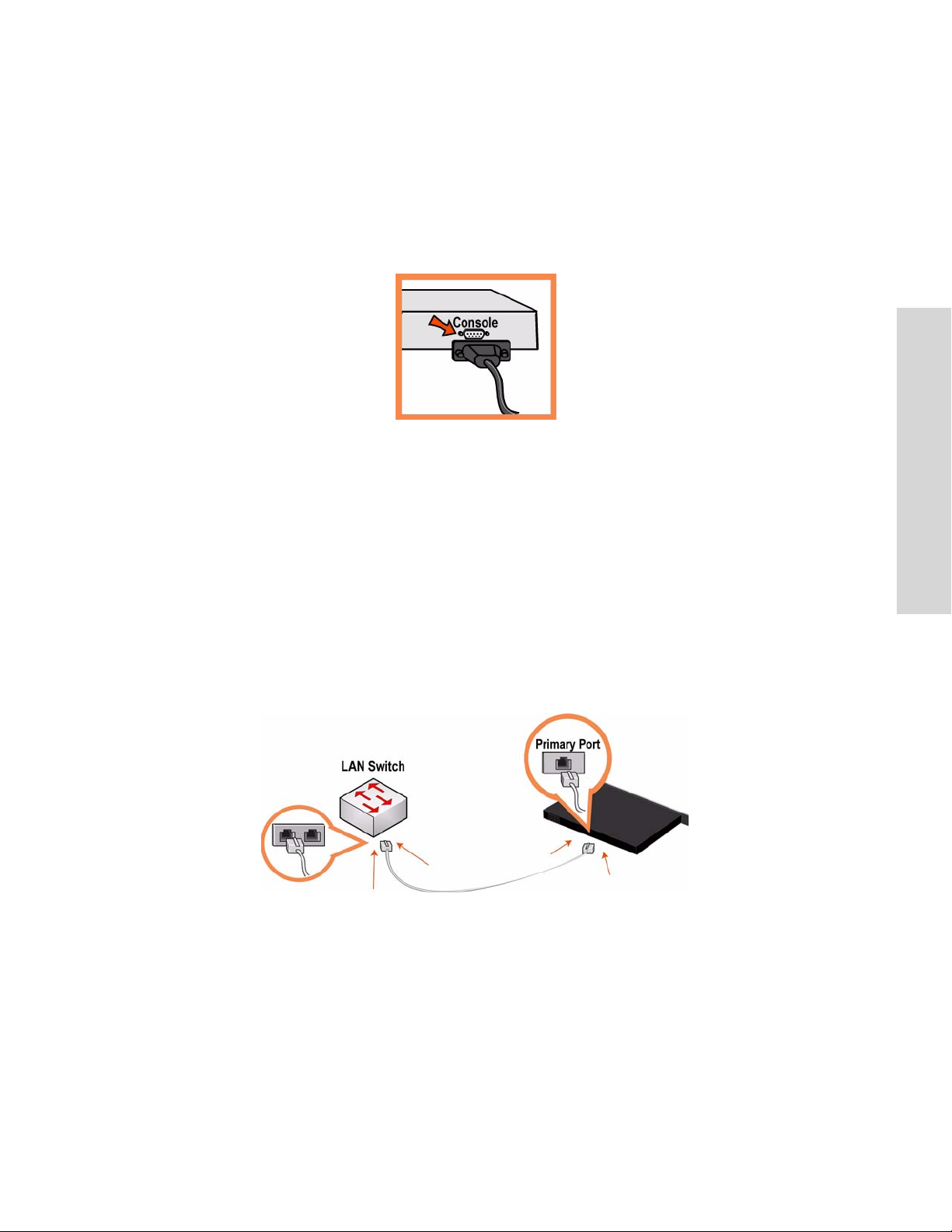
5. Connessione al Mobile Controller
Collegare il cavo seriale alla porta Console e a un terminale.
Verificare che le impostazioni della porta Console siano: 9600, 8 bit di dati, nessuna parità, 1 bit di stop,
nessun controllo del flusso.
Avviare un programma di emulazione del terminale, ad esempio HyperTerminal o Tera Term Pro.
Al prompt di accesso digitare admin. La password predefinita è password.
6. Configurazione del Mobile Controller
Al primo accesso all'interfaccia da riga di comando viene automaticamente avviata la procedura
guidata di configurazione.
2 INSTALLING AND DEPLOYING STEELHEAD
M
OBILE
Attenersi alle istruzioni per configurare la rete e le impostazioni dell'interfaccia del percorso diretto tra
client e Mobile Controller.
Verificare le impostazioni e quindi digitare exit per uscire dal sistema.
7. Collegamento del Mobile Controller alla rete
Collegare un cavo dritto tra la porta principale del Mobile Controller e lo switch LAN, utilizzando
qualsiasi porta dello switch LAN configurata per il collegamento a un host.
Verificare le luci di stato dei LED per assicurarsi che l'apparecchiatura sia collegata correttamente.
GETTING STARTED GUIDE 69
Page 70

8. Accesso al Mobile Controller
Immettere l'URL del Mobile Controller nella casella dell'indirizzo del browser Web:
http://host.domain o https://host.domain
Verrà visualizzata la pagina di benvenuto del Mobile Controller.
Nella casella di testo Account digitare admin.
Nella casella di testo Password digitare la password assegnata.
Fare clic su Login per visualizzare la pagina iniziale.
9. Passaggi successivi
Steelhead Mobile è stato sviluppato per essere distribuito sui Mobile Client senza richiedere alcuna
configurazione aggiuntiva. viene infatti fornito con criteri di endpoint e di accelerazione predefiniti per il
pacchetto MSI distribuito sui Mobile Client della rete.
In genere è possibile installare e distribuire Steelhead Mobile senza dovere modificare i criteri predefiniti
forniti con il prodotto. Si consiglia quindi di distribuire Steelhead Mobile sui client Mobile utilizzando i
criteri predefiniti e modificarli solo se necessario.
Se si utilizza il pacchetto MSI predefinito, nella pagina Manage Endpoints - Packages (Gestione
endpoint - Pacchetto) fare clic sull'URL di tale pacchetto e salvarlo sul computer locale.
Distribuire il pacchetto MSI predefinito sui Mobile Client della rete mediante uno strumento di propria
scelta, ad esempio Microsoft SMS.
Verificare l'ottimizzazione e le connessioni dei Mobile Client generando il rapporto Managed
Endpoints (Endpoint gestiti) del Mobile Controller.
NOTA: è possibile modificare i criteri di endpoint e di accelerazione predefiniti per il pacchetto MSI predefinito.
Per informazioni sulla modifica dei criteri predefiniti, consultare la Steelhead Mobile Controller User’s Guide.
安装和部署
本部分说明如何快速安装、配置和部署
Steelhead Mobile
Steelhead Mobile
。如需详细信息,请参见
Documentation Set CD
。
概述
Steelhead Mobile
您能够优化到远程用户的
和
Client
Steelhead appliance
,无论远程用户使用何种类型远程访 问(例 如:拨 号、宽带和无 线)接 入您网 络,均 可让
TCP
通信。
。
Steelhead Mobile
部署由下列组件构成:
Mobile Controller、Mobile
70 2 - INSTALLING AND DEPLOYING STEELHEAD MOBILE
Page 71
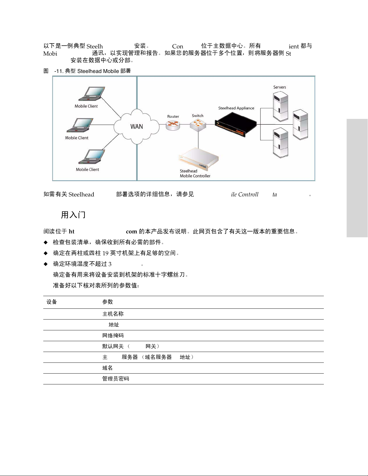
以下是一例典型
Steelhead Mobile
Mobile Controller
appliance
图
2-11.
如需有关
使用入门
1.
安装在数据中心或分部。
典型
Steelhead Mobile
Steelhead Mobile
安装。
Mobile Controller
位于主数据中心。所有
Mobile Client 都与
通讯,以实现管理和报告。如果您的服务器位于多个位置,则将服务器侧
部署
部署选项的详细信息,请参见
Steelhead Mobile Controller Installation Guide
Steelhead
。
2 INSTALLING AND DEPLOYING STEELHEAD
M
OBILE
阅读位于
设备 参数
Mobile Controller
http://www.riverbed.com
的本产品发布说明。此网页包含了有关这一版本的重要信息。
检查包装清单,确保收到所有必需的部件。
确定在两柱或四柱
确定环境温度不超过
英寸机架上有足够的空间。
19
35º C (95º F)
。
确定备有用来将设备安装到机架的标准十字螺丝刀。
准备好以下核对表所列的参数值:
主机名称
地址
IP
网络掩码
默认网关 (
主
域名
管理员密码
服务器 (域名服务器
DNS
WA N
网关)
IP
地址)
GETTING STARTED GUIDE 71
Page 72

Mobile Client
重要:随
默认策略,即可安装和部署
客户端,并仅在必要时修改它们。
Steelhead Mobile
数据储存大小。数据储存至少需要
注:如果您选择不使用随
点策略),您只需要此值。通常情况下,管理员使用随产品提供的默认值部署
,然后在将
Mobile
最大日志大小。默认值为
注:如果您选择不使用随
点策略),您只需要此值。
最大日志文件数量。默认值为 2。
注:如果您选择不使用随
点策略),您只需要此值。
端口号。当您部署
VPN
隧道使用
VPN
添加"直通"规则。取决于您的部署方案,此规则可能成为列表中的首条规则。
如需有关加速策略的详细信息,请参见 Steelhead Mobile Controller User’s Guide
将
IPSec
协议,并且在默认情况下,
如需有关 “通过”规则以及如何设定的详细信息,请参见 Steelhead Mobile Controller User’s
Guide
。
提供的默认
Steelhead Mobile
Steelhead Mobile
进行传输,则您在配置加速策略时,应针对客户端连接到的
TCP
用作传输协议的
程序包旨在适合大多数网络环境。通常情况下,您无需修改随产品提供的
MSI
。考虑使用随产品提供的默认策略将
磁盘空间。默认值为
1 GB
Steelhead Mobile
5000 KB
Steelhead Mobile
Steelhead Mobile
Steelhead Mobile
VPN
。
不需要"直通"规则。这是因为
Steelhead
提供的默认
部署到其
提供的默认
提供的默认
组件时,您需要确保
装置不会优化它。
MSI
Mobile Client
MSI
MSI
Steelhead Mobile
。
10 MB
程序包 (包含默认加速和终结
Steelhead
后再修改这些值。
程序包 (包含默认加速和终结
程序包 (包含默认加速和终结
隧道尚未被优化。如果
VPN
端口号
VPN
。
是其自带的非
IPSec
部署到您的
TCP/IP
Mobile
确保您的
数据储存大小 (GB) 内存使用 (MB)
181
2100
5112
10 161
15 171
20 228
Mobile Client
有足够内存,可以运行
Steelhead Mobile
。
72 2 - INSTALLING AND DEPLOYING STEELHEAD MOBILE
Page 73
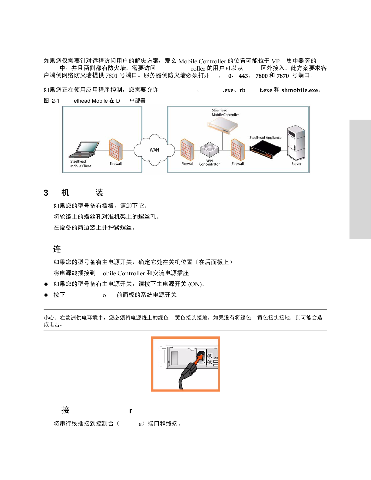
在含防火墙的环境中部署
2.
Steelhead Mobile
如果您仅需要针对远程访问用户的解决 方案, 那么
中,并且两侧都有防火墙。需要访问
DMZ
户端侧网络防火墙提供
如果您正在使用应用程序控制,您需要允许
图
2-12. Steelhead Mobile在 DMZ
在机架上安装
3.
如果您的型号备有挡板,请卸下它。
将轮缘上的螺丝孔对准机架上的螺丝孔。
在设备的两边装上并拧紧螺丝。
号端口。服务器侧防火墙必须打开
7801
中部署
Mobile Controller
rbtdebug.exe、rbtmon.exe、rbtsport.exe 和shmobile.exe
Mobile Controller
的用户可以从
22、80、443、7800 和 7870
的位置可能位于
区外接入。此方案要求客
DMZ
VPN
集中器旁的
号端口。
。
2 INSTALLING AND DEPLOYING STEELHEAD
M
OBILE
连接电源
4.
如果您的型号备有主电源开关,确定它处在关机位置(在后面板上)。
将电源线插接到
如果您的型号备有主电源开关,请按下主电源开关
按下
Mobile Controller
小心:在欧洲供电环境中,您必须将电源线上的绿色/黄色接头接地。如果没有将绿色/黄色接头接地,则可能会造
成电击。
连接到
5.
将串行线插接到控制台(
Mobile Controller
前面板的系统电源开关
Mobile Controller
Console
和交流电源插座。
)端口和终端。
(ON)
。
GETTING STARTED GUIDE 73
Page 74
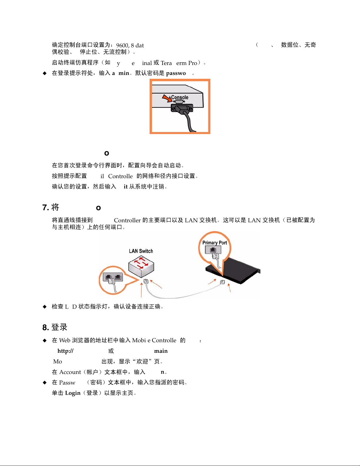
确定控制台端口设置为:
偶校验、
启动终端仿真程序(如
在登录提示符处,输入
配置
6.
在您首次登录命令行界面时,配置向导会自动启动。
按照提示配置
停止位、无流控制)。
1
Mobile Controller
Mobile Controller
9600, 8 data bits, no parity, 1 stop bit, no flow control(9600、8
HyperTerminal 或 Tera Term Pro
。默认密码是
admin
的网络和径内接口设置。
password
数据位、无奇
)。
。
确认您的设置,然后输入
7.将 Mobile Controller
将直通线插接到
与主机
检查
登录到
8.
在
相连
LED
浏览器的地址栏
Web
http://host.domain 或 https://host.domain
Mobile Controller
)上的任何端口。
状态指示灯
Mobile Controller
exit
从系统中注销。
连接到网络
,确认设备连接正确。
中输入
Mobile Controller 的 URL
的主要端口以
及
交换机。这可以是
LAN
:
LAN
交换机(
已被
配置为
出
Mobile Controller
在
Account
在
Password
单
击
74 2 - INSTALLING AND DEPLOYING STEELHEAD MOBILE
(帐户)文本框中,输入
(密码)文本框中,输入您
Login
(登录)以显示主页。
现,显示
“欢迎”
admin
页。
指派
。
的密码。
Page 75
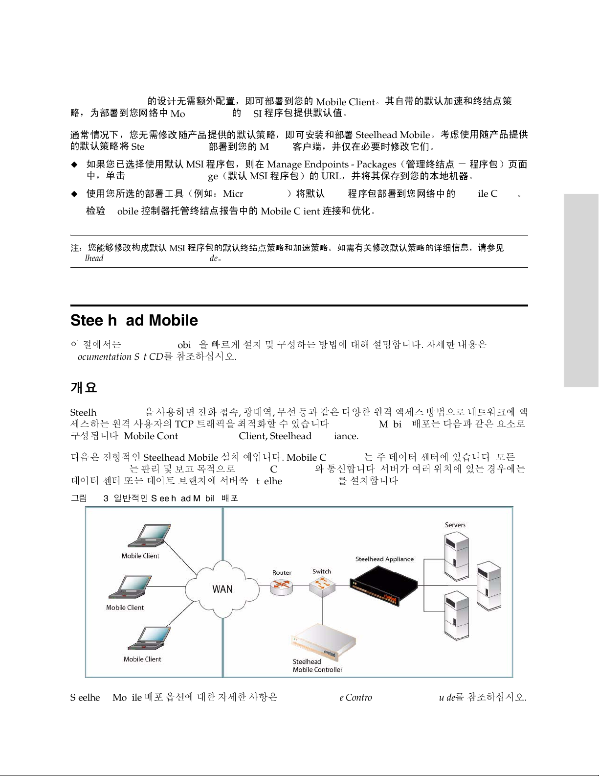
后继步骤
9.
Steelhead Mobile
略
,为部署到您网络中
通
常情况
的默认
注:您能够修改构成默认
Steelhead Mobile Controller User’s Guide
下,您无需
策略
如果您已选择使用默认
中,单
击
使用您所选的部署工具(例如:
检验
Mobile
的设计无需额外配置,即可部署到您的
Mobile Client 的 MSI
修改随
将
Steelhead Mobile
Default MSI Package
产品提供的默认
部署到您的
程序包,则在
MSI
(默认
MSI
Microsoft SMS
控制器托管终
MSI
结点
报告中的
程序包的默认终结点策略和加速策略。如需有关修改默认策略的详细信息,请参见
。
程序包提供默认值。
策略,即
Mobile
Manage Endpoints - Packages
程序包)的
Mobile Client
Steelhead Mobile 설치 및 배포
이 절에서는
Documentation Set CD
Steelhead Mobile을
를 참조하십시오
빠르게 설치 및 구성하는 방법에 대해 설명합니다. 자세한 내용은
.
Mobile Client
可安装和部署
Steelhead Mobile
客户端,并仅在必要时
,并将其保存到您的本地机器。
URL
)将默认
程序包部署到您网络中的
MSI
连
接和优化。
。
其自
带的默认加速和终
。
考虑
修改它们
(管理终
。
结点 - 程序包)页面
结点策
使用随产品提供
Mobile Client
。
2 INSTALLING AND DEPLOYING STEELHEAD
M
OBILE
개요
Steelhead Mobile을
세스하는
구성됩니다
원격
: Mobile Controller, Mobile Client, Steelhead appliance.
다음은 전형적인
Mobile Client
데이터 센터 또는 데이트 브랜치에 서버쪽
그림
2-13.
일반적인
사용하면 전화 접속, 광대역, 무선 등과 같은 다양한 원격 액세스 방법으로 네트워크에 액
사용자의
Steelhead Mobile
는 관리 및 보고 목적으로
TCP
트래픽을 최적화할 수 있습니다
Steelhead Mobile
설치 예입니다
Mobile Controller와
배포
. Steelhead Mobile
. Mobile Controller는 주
통신합니다. 서버가 여러 위치에 있는 경우에는
Steelhead appliance를
데이터 센터에 있습니다. 모든
설치합니다
배포는 다음과 같은 요소로
.
Steelhead Mobile 배포
GETTING STARTED GUIDE 75
옵션에 대한 자세한 사항은
Steelhead Mobile Controller Installation Guide를
참조하십시오
.
Page 76
1. 시작하기
http://www.riverbed.com에 있는
가
포함되어 있습니다
패킹 슬립을 확인하여 필요한 모든 부품이 인도되었는지 확인하십시오
2
개 또는 4개 포트의
실내 온도가
랙에 어플라이언스를 설치하려면 표준형 필립스 스크루드라이버가 있어야 합니다
다음 점검 목록에 있는 매개변수 값이 있어야 합니다
어플라이언스 매개변수
Mobile Controller
Mobile Client
.
19
인치 랙을 설치할 수 있는 충분한 공간이 있는지 확인하십시오
35º C(95º F)를
호스트 이름
IP
주소
넷 마스크
기본 게이트웨이
1차 DNS 서버(
도메인 이름
관리자 암호
데이터 저장소 크기. 데이터 저장소에는 최소
10 MB
참고
: Steelhead Mobile과 함께
값이 필요합니다(기본 가속 및 엔드포인트 정책 포함
된 기본값을 사용하여
포한 후에 수정합니다
제품의 릴리스 정보를 읽으십시오. 여기에는 이 릴리스에 대한 중요 정보
.
초과하지 않도록 주의하십시오
.
.
(WAN
입니다
게이트웨이
도메인 이름 서버
.
Steelhead Mobile을
.
)
IP 주소)
제공되는 기본
배포하고
1 GB의
디스크 공간이 필요합니다. 기본값은
MSI
패키지를 사용하지 않으려는 경우에만 이
).
일반적으로 관리자는
Steelhead Mobile을 Mobile Client에
.
.
제품과 함께 제공
배
최대 로그 크기. 기본값은
참고
: Steelhead Mobile과 함께
값이 필요합니다(기본 가속 및 엔드포인트 정책 포함
최대 로그 파일 수. 기본값은 2입니다
참고
: Steelhead Mobile과 함께
값이 필요합니다(기본 가속 및 엔드포인트 정책 포함
VPN 포트 번호. Steelhead Mobile(
되지 않았는지 확인해야 합니다
(acceleration policy)을
을 추가하십시오. 배치 시나리오에 따라, 이 규칙은 목록에서 첫 번째 규칙이 될 수 있습니다
가속 정책
롤러 사용자 설명서를
전송 프로토콜로
TCP/IP
습니다
통과 규칙 및 설정 방법에 대한 자세한 내용은
하십시오
(acceleration policy)에 관한
IPSec 를
프로토콜이기 때문이며
.
.
5000 KB
설정하는 경우에는 클라이언트에 접속된
참조하십시오
사용하는
입니다
.
제공되는 기본
.
제공되는 기본
스틸헤드 모바일) 부품을 배치할 경우
. VPN
.
VPN은
Steelhead(
MSI
패키지를 사용하지 않으려는 경우에만 이
).
MSI
패키지를 사용하지 않으려는
).
터널이 전송용
자세한 사항은
통과규칙이 필요 없습니다. 그 이유는
스틸헤드) 기기는 기본값으로 이를 최적화하지 않
TCP 를
, Steelhead Mobile(
Steelhead Mobile Controller User’s Guide를
VPN
터널이 최적화
사용하고, 가속 정책
VPN 포트
번호용 통과 규칙
스틸헤드 모바일) 컨트
경우에만 이
IPSec는 비
참조
.
76 2 - INSTALLING AND DEPLOYING STEELHEAD MOBILE
Page 77
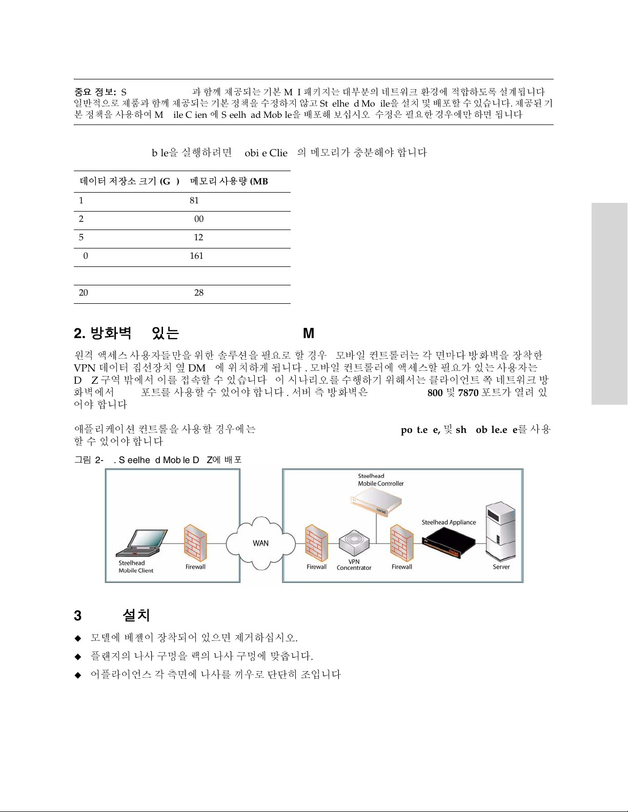
중요 정보
일반적으로 제품과 함께 제공되는 기본 정책을 수정하지 않고
본 정책을 사용하여
Steelhead Mobile
데이터 저장소 크기
181
2100
5112
10 161
15 171
20 228
: Steelhead Mobile과 함께
Mobile Client에 Steelhead Mobile을
을 실행하려면
(GB)
메모리 사용량
제공되는 기본
MSI
Mobile Client의
(MB)
패키지는 대부분의 네트워크 환경에 적합하도록 설계됩니다
Steelhead Mobile을 설치 및
배포해 보십시오. 수정은 필요한 경우에만 하면 됩니다
메모리가 충분해야 합니다
배포할 수 있습니다. 제공된 기
.
.
2. 방화벽이 있는 환경에 Steelhead Mobile 배포
원격 액세스 사용자들만을 위한 솔루션을 필요로 할 경우, 모바일 컨트롤러는 각 면마다 방화벽을 장착한
VPN
데이터 집선장치 옆
DMZ
구역 밖에서 이를 접속할 수 있습니다. 이 시나리오를 수행하기 위해서는 클라이언트 쪽 네트워크 방
화벽에서
어야
7801
합니다
포트를 사용할 수 있어야 합니다. 서버 측 방화벽은
.
DMZ에
위치하게 됩니다. 모바일 컨트롤러에 액세스할 필요가 있는 사용자는
22, 80, 443, 7800 및 7870
포트가 열려 있
.
2 INSTALLING AND DEPLOYING STEELHEAD
M
OBILE
애플리케이션 컨트롤을 사용할 경우에는
할
수
있어야 합니다
그림
2-14. Steelhead Mobile DMZ에
.
배포
rbtdebug.exe, rbtmon.exe, rbtsport.exe, 및 shmobile.exe를
3. 랙에 설치
모델에 베젤이 장착되어 있으면 제거하십시오
플랜지의 나사 구멍을 랙의 나사 구멍에 맞춥니다
어플라이언스 각 측면에 나사를 끼우로 단단히 조입니다
.
사용
.
.
GETTING STARTED GUIDE 77
Page 78
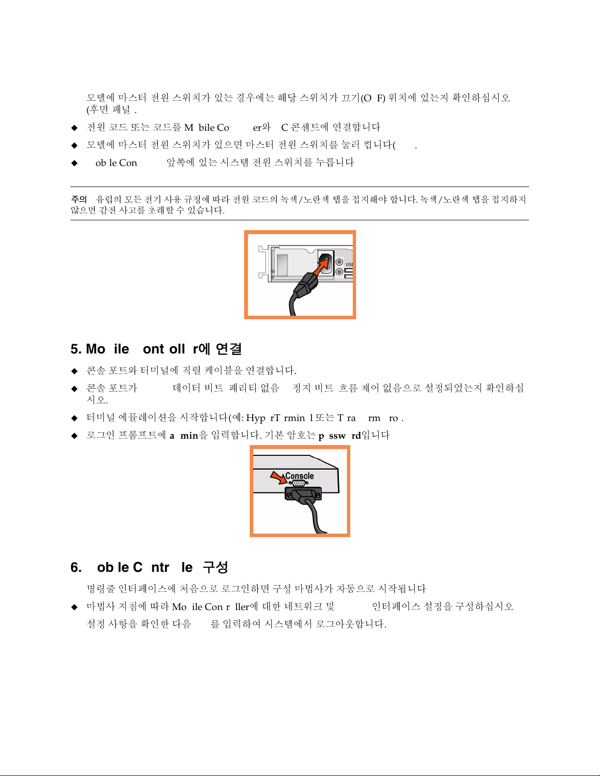
4. 전원 연결
모델에 마스터 전원 스위치가 있는 경우에는 해당 스위치가 끄기
(후면 패널).
전원 코드 또는 코드를
모델에 마스터 전원 스위치가 있으면 마스터 전원 스위치를 눌러 켭니다
Mobile Controller와 AC
콘센트에 연결합니다
(OFF)
위치에 있는지 확인하십시오
.
(ON).
Mobile Controller
주의
:
유럽의 모든 전기 사용 규정에 따라 전원 코드의 녹색/노란색 탭을 접지해야 합니다. 녹색/노란색 탭을 접지하지
않으면 감전 사고를 초래할 수 있습니다
앞쪽에 있는 시스템 전원 스위치를 누릅니다
.
.
5. Mobile Controller에 연결
콘솔 포트와 터미널에 직렬 케이블을 연결합니다
콘솔 포트가
.
시오
터미널 에뮬레이션을 시작합니다(예
로그인 프롬프트에
9600, 8
데이터 비트, 패리티 없음
: HyperTerminal 또는 Tera Term Pro).
admin을
입력합니다. 기본 암호는
.
, 1 정지 비트, 흐름
password
제어 없음으로 설정되었는지 확인하십
입니다
.
6. Mobile Controller 구성
명령줄 인터페이스에 처음으로 로그인하면 구성 마법사가 자동으로 시작됩니다
마법사 지침에 따라
설정 사항을 확인한 다음
78 2 - INSTALLING AND DEPLOYING STEELHEAD MOBILE
Mobile Controller에
exit를
입력하여 시스템에서 로그아웃합니다
대한 네트워크 및
In-Path
인터페이스 설정을 구성하십시오
.
.
.
Page 79
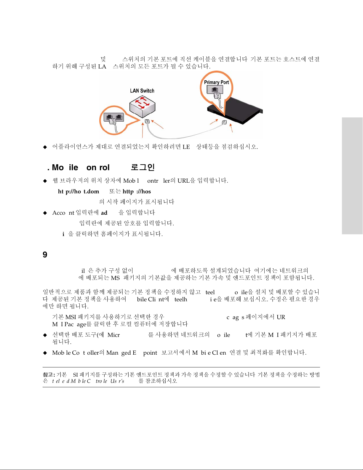
7. 네트워크에 Mobile Controller 연결
Mobile Controller
하기
위해 구성된
어플라이언스가 제대로 연결되었는지 확인하려면
및
LAN
스위치의 기본 포트에 직선 케이블을 연결합니다. 기본 포트는 호스트에 연결
LAN
스위치의 모든 포트가 될 수 있습니다
8. Mobile Controller에 로그인
웹 브라우저의 위치 상자에
http://host.domain
Mobile Controller
Account
Password
입력란에
입력란에 제공된 암호를 입력합니다
의 시작 페이지가 표시됩니다
admin을
Mobile Controller의 URL을
또는
https://host.domain
입력합니다
.
.
.
.
LED
상태등을 점검하십시오
입력합니다
2 INSTALLING AND DEPLOYING STEELHEAD
.
M
OBILE
.
Login
을 클릭하면 홈페이지가 표시됩니다
.
9. 다음 단계
Steelhead Mobile은
Mobile Client
일반적으로 제품과 함께 제공되는 기본 정책을 수정하지 않고
다
.
제공된 기본 정책을 사용하여
에만
하면 됩니다
기본
MSI
MSI Package
선택한 배포 도구(예
됩니다
Mobile Controller
참고: 기본
은
Steelhead Mobile Controller User’s Guide를
.
MSI
추가 구성 없이
에 배포되는
MSI
Mobile Client에
배포하도록 설계되었습니다. 여기에는 네트워크의
패키지의 기본값을 제공하는 기본 가속 및 엔드포인트 정책이 포함됩니다
Mobile Client에 Steelhead Mobile을
.
패키지를 사용하기로 선택한 경우
를 클릭한 후 로컬 컴퓨터에 저장합니다
: Microsoft SMS)를
의
Managed Endpoints
패키지를 구성하는 기본 엔드포인트 정책과 가속 정책을 수정할 수 있습니다. 기본 정책을 수정하는 방법
참조하십시오
Manage Endpoints - Packages
.
사용하면 네트워크의
보고서에서
Mobile Client
.
Steelhead Mobile을
배포해 보십시오. 수정은 필요한 경우
페이지에서
Mobile Client에
연결 및 최적화를 확인합니다
.
설치 및 배포할 수 있습니
URL for Default
기본
MSI
패키지가 배포
.
GETTING STARTED GUIDE 79
Page 80
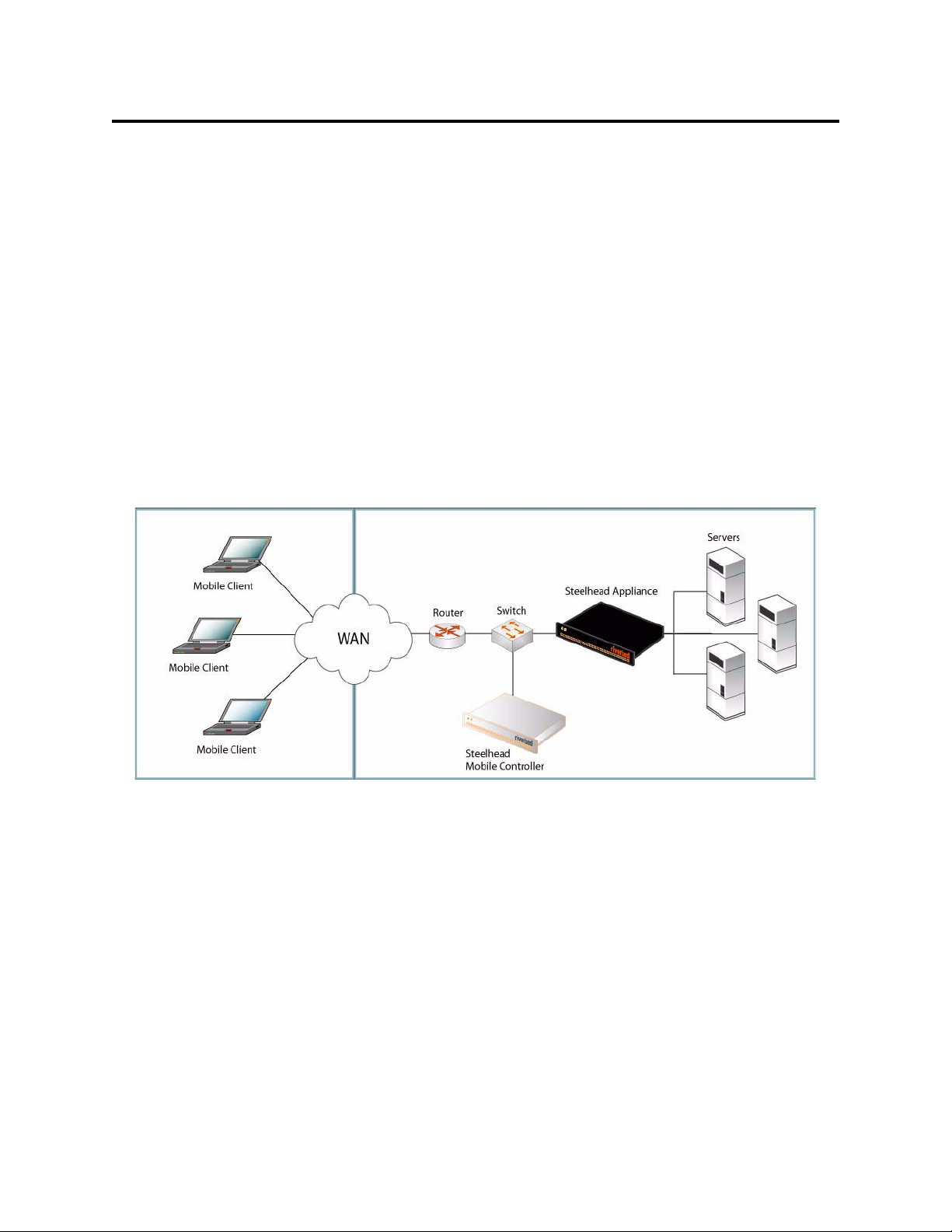
Установка и ввод в действие устройства Steelhead Mobile
В этой главе разъясняется, как быстро установить, конфигурировать и ввести в действие устройство
Steelhead Mobile. Подробные сведения см. в
Обзор
Steelhead Mobile позволяет оптимизировать TCP-трафик для удаленных пользователей с любым
типом дистанционного доступа к вашей сети (например, по телефонной линии, через
широкополосный канал или по радиоканалу). Система Steelhead Mobile состоит из следующих
компонентов: Mobile Controller, Mobile Client и Steelhead appliance.
Далее приведен типичный пример установки Steelhead Mobile. Mobile Controller располагается в
главном центре регистрации и обработки данных. Все Mobile Client связываются с Mobile Controller в
целях организации управления
расположенных в разных местах, установите серверную часть Steelhead applianceв центрах
регистрации и обработки данных или в их филиалах.
Рисунок 2-15. Типово е размещение Steelhead Mobile
и отчетности. Если у вас имеется несколько серверов,
Documentation Set CD
.
Подробные сведения о вариантах размещения системы Steelhead Mobile см. в руководстве
Mobile Controller Installation Guide
.
Steelhead
1. Начало работы
Прочтите примечания к версии изделия на сайте http://www.riverbed.com. В них содержится важная
информация об этом выпуске.
Проверьте имеющуюся у вас упаковочную ведомость, чтобы убедиться в наличии всех
необходимых деталей.
Удостоверьтесь, что у вас имеется достаточно места на двух- или четырехпостовой
19-дюймовой стойке.
Убедитесь, что температура окружающей среды не превышает 35ºC (95ºF).
80 2 - INSTALLING AND DEPLOYING STEELHEAD MOBILE
Page 81

Убедитесь, что у вас есть стандартная крестообразная отвертка, с помощью которой вы будете
устанавливать устройство в стойку.
Подготовьтесь к установке значений параметров, перечисленных в следующем контрольном
перечне:
Устройство Параметр
Mobile Controller Имя хоста
IP-адрес
Маска сети
Шлюз по умолчанию (шлюз WAN)
Основной сервер DNS (IP-адрес сервера доменных имен)
Имя домена
Пароль Администратора
Mobile Client Емкость памяти для хранения данных. Для хранения данных на диске требуется не
менее 1 ГБ . Значение по умолчанию 10 МБ.
ПРИМЕЧАНИЕ: Указанная емкость необходима только в том случае, когда не
используется заданный по умолчанию
пакет MSI (содержащий заданные по
умолчанию стратегии ускорения и конечных точек), который поставляется вместе с
Steelhead Mobile. Как правило, администраторы вводят Steelhead Mobile в действие,
используя значения по умолчанию (предоставляемые вместе с изделием), и изменяют
их после ввода Steelhead Mobile в действие для своих Mobile Client.
Максимальный размер журнала регистрации. Значение по умолчанию: 5000 КБ.
ПРИМЕЧАНИЕ: Указанный размер необходим только в том случае, когда не
используется заданный по умолчанию пакет MSI (содержащий заданные по
умолчанию стратегии ускорения и конечных точек), который поставляется вместе с
Steelhead Mobile.
Максимальное количество файлов регистрации. По умолчанию задано значение 2.
ПРИМЕЧАНИЕ: Указанное количество необходимо только в том случае, когда не
используется заданный по умолчанию пакет MSI (содержащий заданные по
умолчанию стратегии ускорения и конечных точек), который поставляется вместе с
Steelhead Mobile.
2 INSTALLING AND DEPLOYING STEELHEAD
M
OBILE
Номер порта VPN.При развертывании компонентов Steelhead Mobile убедитесь в том,
что VPN-туннель не оптимизирован. Если для VPN-туннеля в качестве транспортного
протокола используется TCP, настройте политику ускорения, добавьте правило
транзитной пересылки для номера VPN-порта, к которому подключен клиент. В
зависимости от порядка развертывания это
правило может быть первым в списке
правил.
Подробную информацию о политиках ускорения см. в
User’s Guide
.
Steelhead Mobile Controller
Для сетей VPN, в которых в качестве транспортного протокола используется протокол
IPSec, правило транзитной пересылки не требуется. Причина заключается в том, что
IPSec сам по себе является протоколом, отличным от TCP/IP, и по умолчанию
устройства Steelhead его не оптимизируют.
Подробные сведения о правилах прохождения и их задании см. в руководстве
Steelhead Mobile Controller User’s Guide
GETTING STARTED GUIDE 81
Page 82
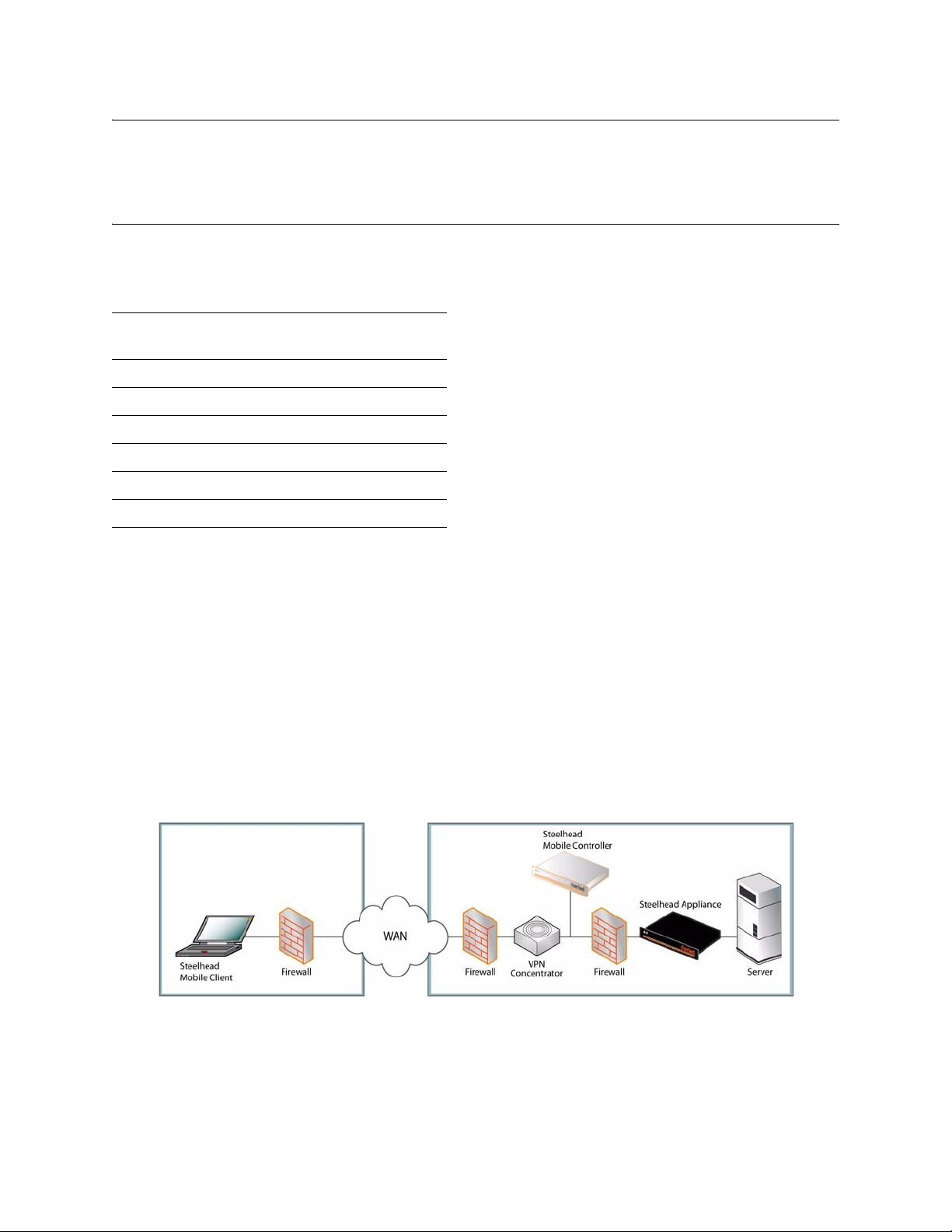
ВАЖНЊ! Пакет MSI значений по умолчанию, поставляемый вместе с Steelhead Mobile, пригоден для
использования в большинстве сетевых сред. Как правило, установить и ввести в действие Steelhead Mobile
можно без изменения принятых по умолчанию стратегий, поставляемых вместе с изделием. Рассмотрите
вариант применения Steelhead Mobile для своих мобильных клиентов (Mobile Clients) с использованием
стратегий, принятых по умолчанию, и изменяйте их только в случае необходимости.
Обеспечьте на своих устройствах Mobile Clientобъем памяти, достаточный для работы Steelhead
Mobile.
Емкость памяти для
хранения данных (ГБ)
181
2 100
5112
10 161
15 171
20 228
Использование
памяти (МБ)
2. Размещение Steelhead Mobile в средах со шлюзами безопасности
Если необходимо решение только для пользователей с удаленным доступом, мобильный
контроллер можно установить в демилитаризованной зоне рядом с концентратором VPN с
брандмауэрами по обеим сторонам. Пользователи, которым необходим доступ к мобильному
контроллеру, могут подключаться к нему за пределами демилитаризованной зоны. При
использовании такого сценария необходимо, чтобы был доступен порт 7801 брандмауэра на
клиентской стороне сети. В брандмауэре на стороне сервера должны быть открыты порты 22, 80,
443, 7800 и 7870.
При использовании системы контроля приложений необходимо создать разрешения для
rbtdebug.exe, rbtmon.exe, rbtsport.exe и shmobile.exe.
Рисунок 2-16. Steelhead Mobile Размещение в DMZ
3. Установка в стойку
Если в вашем устройстве имеется фальш-панель, снимите ее.
Совместите отверстия для винтов на фланцах с отверстиями для винтов на стойке.
82 2 - INSTALLING AND DEPLOYING STEELHEAD MOBILE
Page 83

Вставьте и затяните винты с каждой стороны устройства.
2 INSTALLING AND DEPLOYING STEELHEAD
M
OBILE
GETTING STARTED GUIDE 83
Page 84
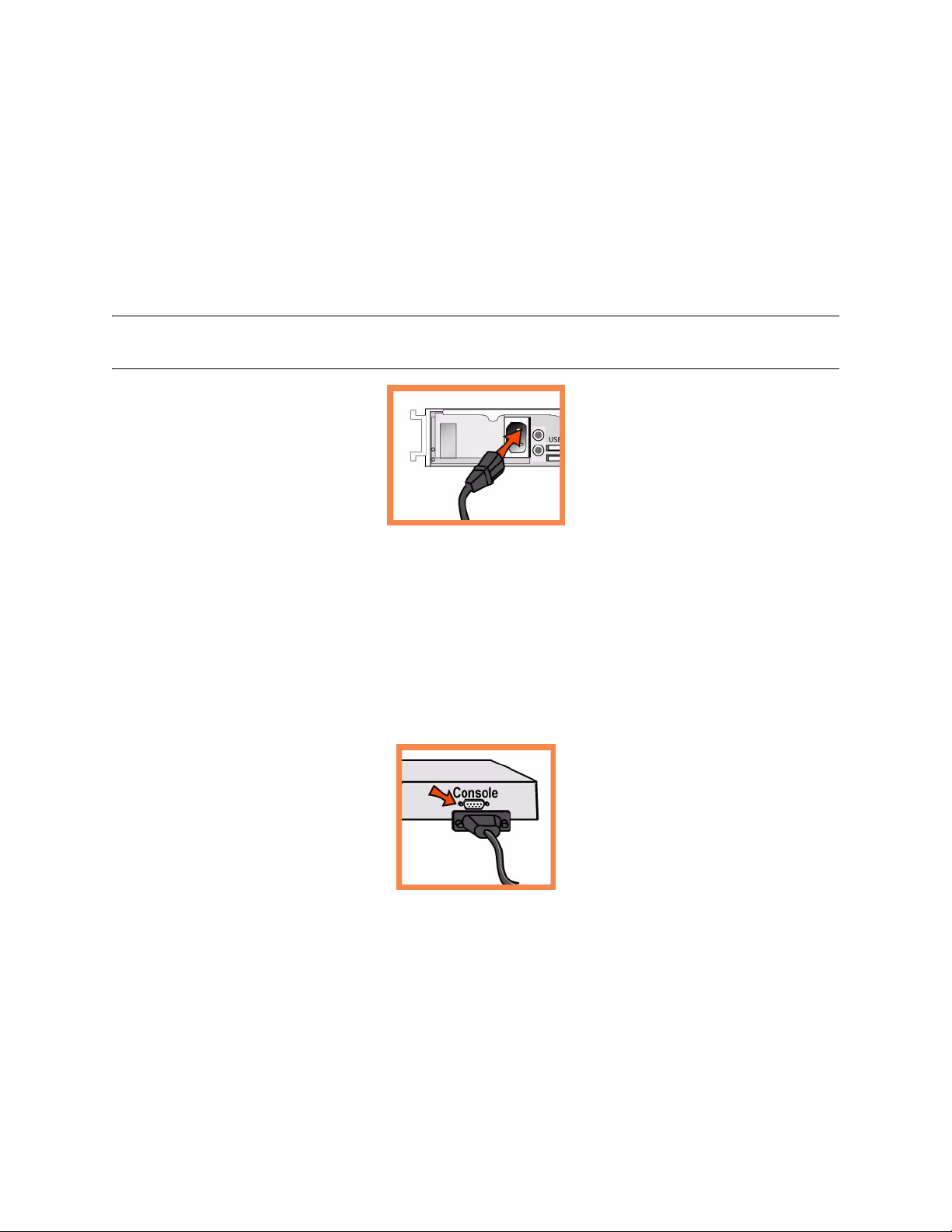
4. Подключение электропитания
Если ваша модель устройства имеет главный выключатель электропитания, убедитесь, что он
находится в положении ВЫКЛ (OFF) (расположен на задней панели).
Подсоедините шнур или шнуры питания к Mobile Controller и вставьте их в сетевую розетку.
Если ваша модель имеет главный выключатель электропитания, нажмите главный выключатель
питания и переведите его в положение ВКЛ (ON).
Нажмите переключатель питания системы на передней панели Mobile Controller.
ПРЕДОСТЕРЕЖЕНИЭ! В электросетях всех европейских стран требуется заземлять зеленую/желтую клемму на
сетевом шнуре. В противном случае возможно поражение электрическим током.
5. Подключение к Mobile Controller
Вставьте кабель последовательного интерфейса в порт консоли и в разъем терминала.
Убедитесь, что настройки порта консоли следующие: 9600, 8 бит данных, отсутствие паритета,
1 стоповый бит, нет контроля передачи.
Запустите программу эмуляции терминала (например, HyperTerminal или Tera Ter m P r o ) .
Когда появится приглашение на вход в систему, наберите слово admin. Паролем по умолчанию
является слово password..
6. Конфигурирование Mobile Controller
Мастер конфигурирования запускается автоматически при первом входе в интерфейс
командной строки.
Следуйте появляющимся подсказкам для конфигурирования сети и установки настроек
внутриканального интерфейса для устройства Mobile Controller.
Подтвердите настройки, затем наберите exit, чтобы выйти из системы.
84 2 - INSTALLING AND DEPLOYING STEELHEAD MOBILE
Page 85
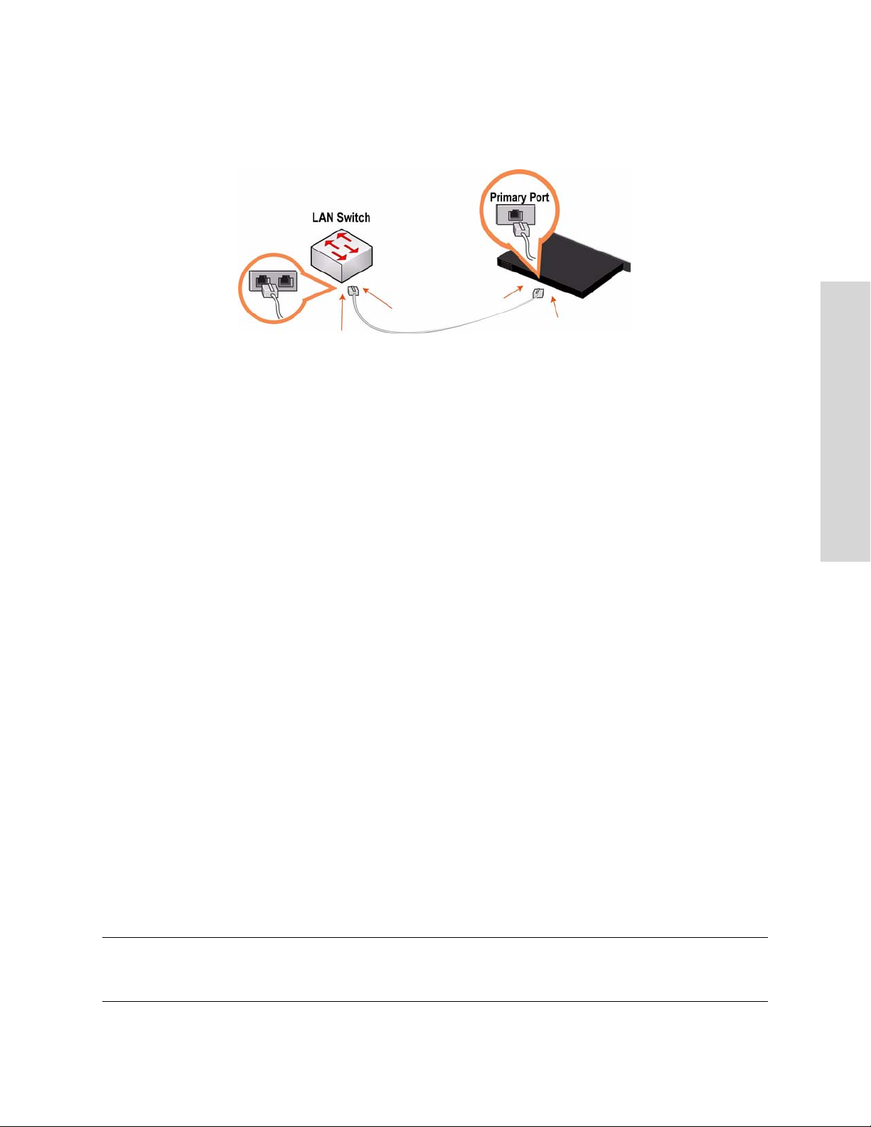
7. Подключение устройства Mobile Controller к сети
Прямым кабелем соедините первичный порт устройства Mobile Controller с портом коммутатора ЛВС.
Это может быть любой порт на вашем коммутаторе ЛВС, конфигурированный для подключения к хосту.
Проверьте свечение светодиодов состояния, чтобы убедиться в надлежащем подключении устройства.
8. Регистрация в журнале устройства Mobile Controller
Введите URL для устройства Mobile Controller в поле местоположения на вашем веб-браузере :
http://host.domain or https://host.domain
2 INSTALLING AND DEPLOYING STEELHEAD
M
OBILE
Откроется окно Mobile Controller и отобразится страница с приглашением.
В текстовое поле Account (Учетная запись) наберите admin.
В текстовое поле Password (Пароль) наберите выданный вам пароль.
Нажмите кнопку Login для отображения главной страницы.
9. Последующие действия
Устро йс т во Steelhead Mobile предназначено для размещения для Mobile Client без выполнения
дополнительной конфигурации. Устройство поставляется с заданными по умолчанию стратегиями
ускорения и конечных точек, предоставляющими значения по умолчанию для пакета MSI,
используемого для Mobile Client вашей сети.
Как правило, устройство Steelhead Mobile установливается и вводится в действие без изменения
принятых по умолчанию стратегий, поставляемых вместе с изделием. Рассмотрите вариант
применения
стратегий, принятых по умолчанию, и изменяйте их только в случае необходимости.
Если вы решили использовать заданный по умолчанию пакет MSI, - на странице Manage Endpoints -
Packages щелкните по URL для пакета MSI по умолчанию, и сохраните его в своей локальной машине.
Используя инструмент размещения по собственному выбору (например, Microsoft SMS),
используйте для Mobile Client своей сети пакет MSI, заданный по умолчанию.
В отчете Managed Endpoints устройства Mobile Controller проверьте подключения и оптимизацию
Mobile Client.
Steelhead Mobile для своих мобильных клиентов (Mobile Clients) с использованием
ПРИМЕЧАНИЕ. Вы можете изменить заданные по умолчанию стратегии ускорения и конечных точек,
составляющих заданный по умолчанию пакет MSI. Подробные сведения о процедуре изменения стратегий,
принятых по умолчанию, см. в руководстве
GETTING STARTED GUIDE 85
Steelhead Mobile Controller User’s Guide
.
Page 86

86 2 - INSTALLING AND DEPLOYING STEELHEAD MOBILE
Page 87

CHAPTER 3 Installing the Central
Management Console
In This Chapter
This chapter describes how to quickly install and configure the Central Management Console (CMC) in
English and other languages. For detailed information about installing and configuring the CMC, see the
Steelhead Central Management Console User’s Guide.
Installing the CMC
This section describes how to quickly install and configure the CMC appliance. The CMC allows you to
configure and manage remote Steelhead appliances from a central location. For detailed information, see
the Documentation Set CD.
1. Getting Started
Read the release notes for the product at http://www.riverbed.com. They contain important information
about this release.
Check your packing slip to make sure that you have all the necessary parts.
Make sure you have adequate space on a two or four post, 19-inch rack.
Make sure that the ambient temperature does not exceed 35º C (95º F).
Make sure you have a standard Phillips screwdriver to install the appliance to a rack.
Gather the necessary information:
CMC appliance: Host and IP address
Network: netmask, default gateway, DNS IP address, and domain name
Remote Steelhead appliances: IP addresses, administrative user names, administrative passwords
C
ONSOLE
3 INSTALLING THE CENTRAL MANAGEMENT
2. Installing on a Rack
If your model has a bezel, remove it.
Align the screw holes on the flanges with the screw holes on the rack.
GETTING STARTED GUIDE 87
Page 88
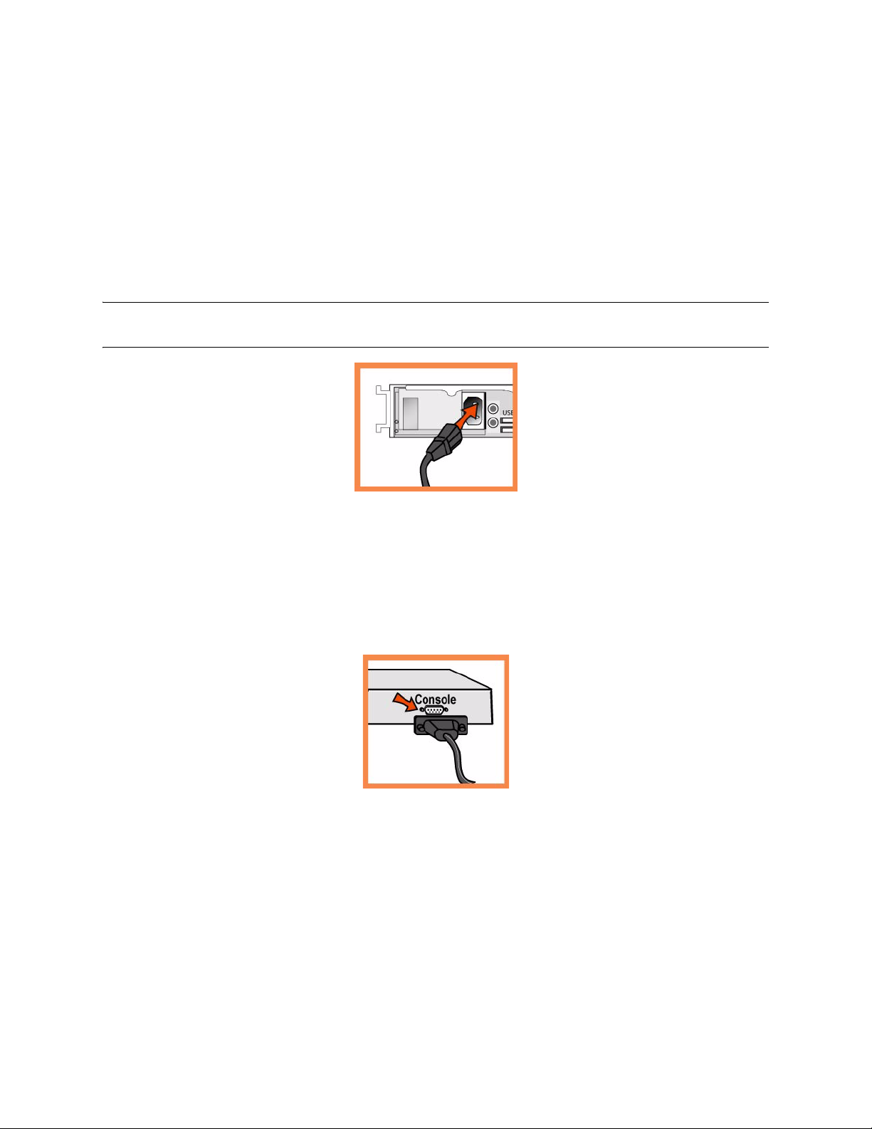
Insert and tighten the screws on each side of the appliance.
3. Connecting the Power
If your model has a master power switch, make sure it is in the off position (on the rear panel).
Plug the power cord or cords into the CMC and an AC outlet.
If your model has a master power switch, press in the master power switch (ON).
Press in the system power switch on the front of the CMC.
CAUTION: In all European electrical environments, you must ground the Green/Yellow tab on the power cord. If you
do not ground the Green/Yellow tab, it can cause electrical shock.
4. Connecting to the CMC
Plug the serial cable into the Console port and a terminal.
Make sure the Console port settings are: 9600, 8 data bits, no parity, 1 stop bit, no flow control.
Start your terminal emulation program (for example, HyperTerminal or Tera Term Pro).
At the login prompt, type admin. The default password is password.
5. Configuring the CMC
The configuration wizard automatically starts when you log into the command-line interface for the
first time.
Follow the prompts to configure network and in-path interface settings for the CMC.
Confirm your settings; then type exit to log out of the system.
6. Connecting the CMC to Your Network
Make sure you use the correct cables to connect to your network:
88 3 - INSTALLING THE CENTRAL MANAGEMENT CONSOLE
Page 89
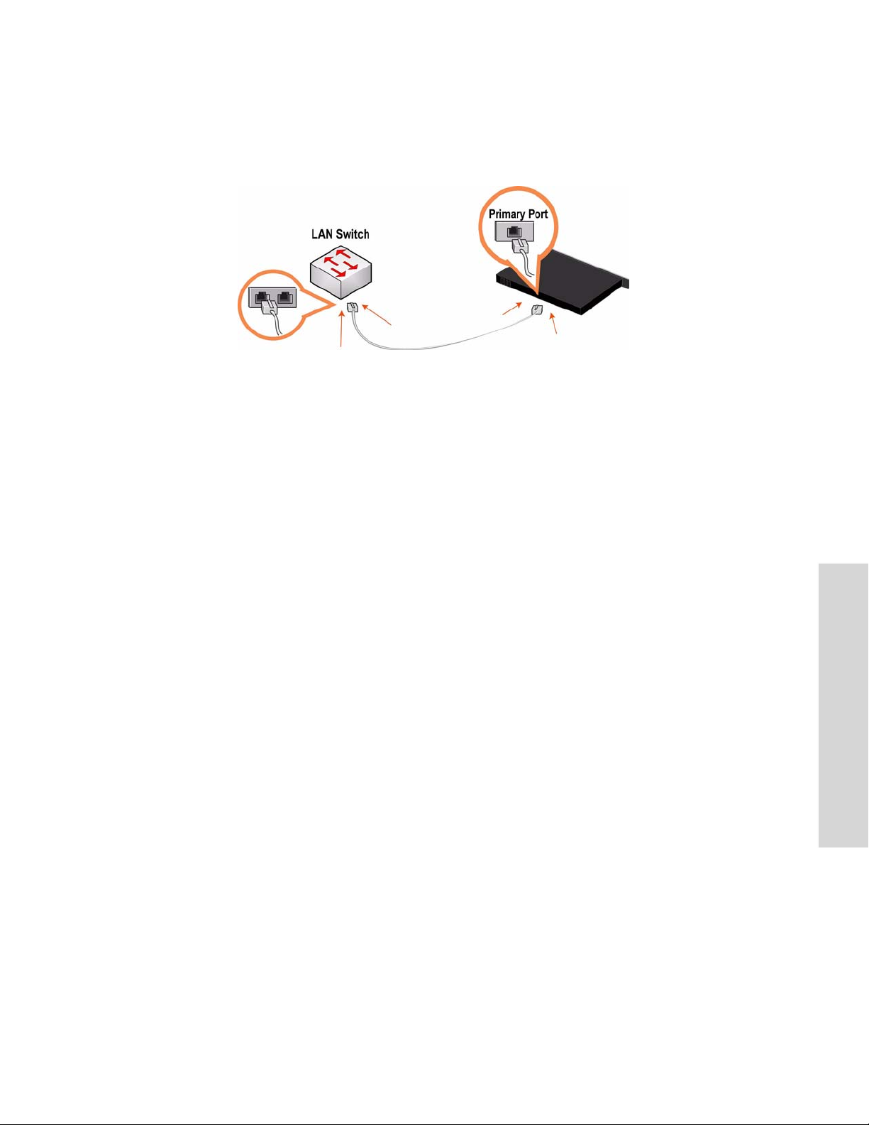
Straight-through cables: Primary and LAN ports to LAN switch.
Cross-over cable: WAN port to WAN router.
Plug the straight-through cable into the Primary port of the CMC appliance and the LAN switch. This
can be any port on your LAN switch that is configured to connect to a host.
7. Checking Your Connections
Check the LED status lights to verify that the appliance is connected properly.
Connect to the CLI. At the system prompt, enter the following command:
ssh [email protected] or ssh admin@ipaddress
At the system prompt, enter ping commands to verify the connections. For example:
ping -I <primary-IP-address> <primary-default-gateway>
8. Logging into the CMC
Enter the URL for the CMC in the location box of your Web browser:
http://host.domain or https://host.domain
The CMC appears, displaying the Welcome page.
In the Account text box, type admin.
In the Password text box, type the password you assigned.
Click Login to display the Home page.
9. Creating Appliance Profiles
Click Setup Appliances to expand the Setup Appliances menu.
Click Profiles to display the Appliance Profiles page.
Create profiles for the types of remote appliances in your system.
C
ONSOLE
3 INSTALLING THE CENTRAL MANAGEMENT
10. Creating Appliance Groups
Click Setup Appliances to expand the Setup Appliances menu.
Click Groups to display the Appliance Groups page.
Create groups for the types of remote appliances in your system.
GETTING STARTED GUIDE 89
Page 90

11. Registering Steelhead Appliances
Click Setup Appliances to display the Setup Appliances: Registration- Appliances page.
Register remote appliances with the CMC, as described in the online help.
Guía rápida de instalación de la consola CMC
Esto capitulo describe cómo instalar y configurar rápidamente el dispositivo CMC. El dispositivo CMC
permite configurar y administrar a distancia los dispositivos Steelhead desde una ubicación central. Para
obtener más información, consulte el CD de documentación de Riverbed. Esta guía incluye instucciones y
advertencias de seguridad.
1. Introducción
Lea las notas de la versión correspondientes al producto en http://www.riverbed.com. Allí encontrará
información importante.
Compruebe con la lista de empaque si tiene todas las piezas necesarias.
Asegúrese de contar con el espacio necesario en un bastidor de dos o cuatro postes de 48,26 cm (19
pulgadas).
Asegúrese de que la temperatura ambiente no supere los 35º C (95º F).
Tenga a mano un destornillador Phillips estándar para instalar el dispositivo en el bastidor. En caso de
falla debe ser reparado exclusivamente por personal téchnico calificado designado por la empresa
importadora y/o responsable legal.
Reúna la siguiente información:
– Dispositivo CMC: dirección de host y de IP
– Red: máscara de red, portal predeterminado, dirección IP de DNS y nombre de dominio
– Dispositivos Steelhead remotos: direcciones IP, nombres de usuario administrativos, contraseñas
administrativas
2. Instalación en un bastidor
Si su modelo cuenta con un bisel, retírelo.
Alinee los orificios para tornillos de las bridas con sus pares en el bastidor.
Inserte los tornillos ubicados a ambos lados del dispositivo y ajústelos.
3. Conexión de la fuente de alimentación
Si su modelo cuenta con un interruptor de encendido maestro, asegúrese de que esté en la posición de
apagado (en el panel posterior).
Enchufe el o los cables de alimentación en el dispositivo CMC y en el tomacorriente de CA.
Si su modelo cuenta con un interruptor de encendido maestro, colóquelo en la posición de encendido.
90 3 - INSTALLING THE CENTRAL MANAGEMENT CONSOLE
Page 91
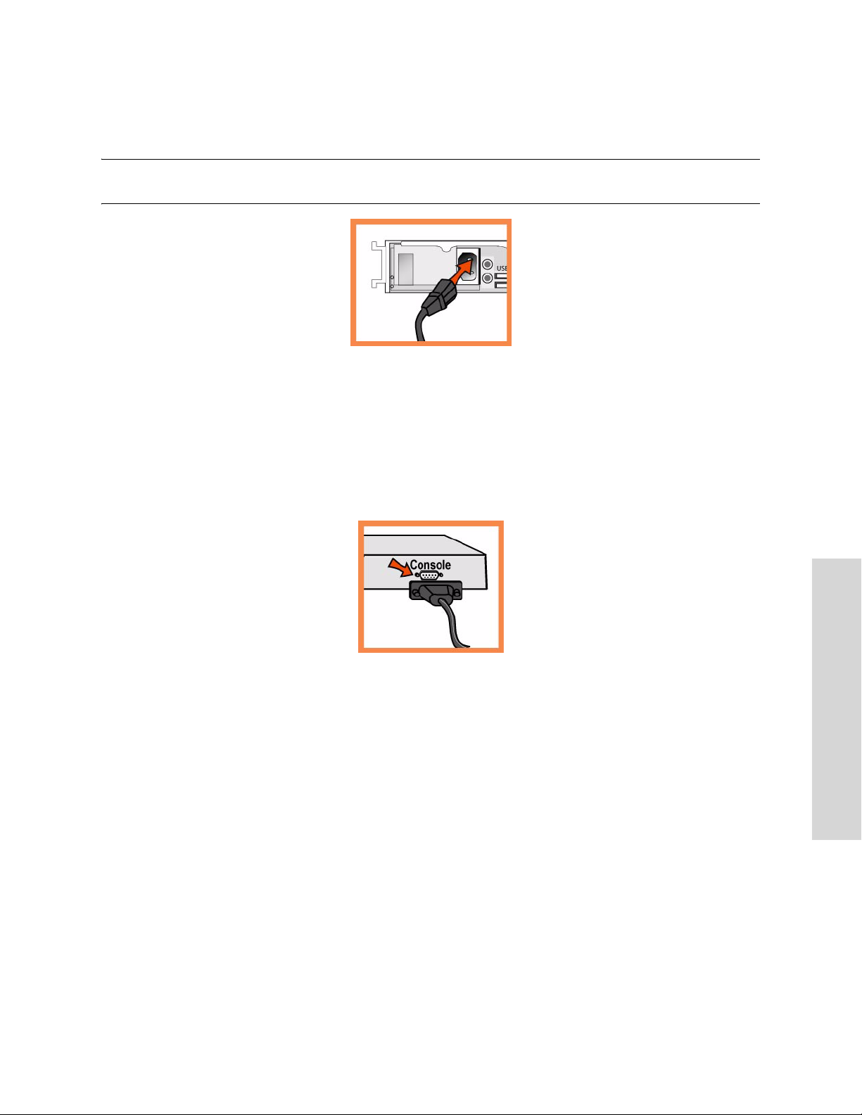
Coloque en la posición de encendido el interruptor de encendido del sistema que se encuentra en la
parte frontal del dispositivo CMC.
ADVERTENCIA: En todos los entornos eléctricos europeos, deberá conectar a tierra la lengüeta verde o amarilla del
cable de alimentación. De lo contrario, se podría producir un choque eléctrico..
4. Conexión con el Dispositivo CMC
Enchufe el cable serial en el puerto de la consola y en una terminal.
Asegúrese de que los ajustes del puerto de la consola sean los siguientes: 9600, 8 bits de datos, sin
paridad, un bit de parada, sin control de flujo.
Inicie el programa de emulación de terminal (por ejemplo, HyperTerminal o Tera Term Pro).
En indicador de inicio de sesión, escriba admin. La contraseña predeterminada es password.
5. Configuración del Dispositivo CMC
El asistente de configuración se inicia automáticamente al iniciar la sesión en la interfaz de línea de
comando por primera vez.
Siga las indicaciones para configurar el equipo.
Confirme la configuración y, a continuación, escriba exit para cerrar la sesión con el sistema.
C
ONSOLE
3 INSTALLING THE CENTRAL MANAGEMENT
GETTING STARTED GUIDE 91
Page 92
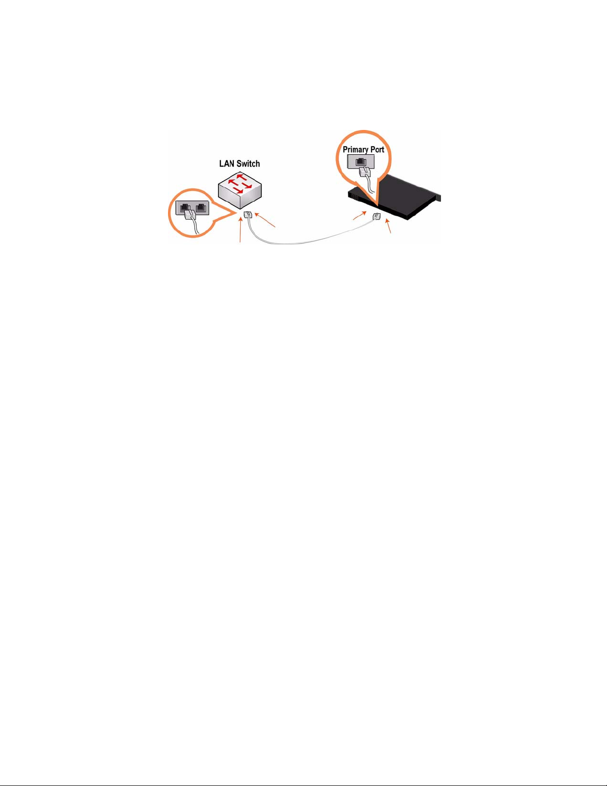
6. Conexión del Dispositivo CMC con la red
Enchufe un extremo del cable de conexión directa suministrado en el puerto principal del dispositivo
CMC y el otro en el conmutador LAN (puede ser cualquier puerto del conmutador LAN configurado
para conectarse con el host)..
7. Comprobación de las conexiones
Controle el estado de los indicadores LED para comprobar si el dispositivo está correctamente
conectado.
Conéctese con el CLI de CMC. A continuación del indicador del sistema, escriba el comando siguiente:
ssh [email protected] o ssh admin@ipaddress
A continuación del indicador del sistema, introduzca comandos ping para comprobar las conexiones.
Por ejemplo:
ping -I <dirección-IP-principal> <portal-principal-predeterminado>
8. Conexión con el Dispositivo CMC
Escriba el URL de CMC en el cuadro de dirección del explorador de Internet:
http://host.dominio o https://host.dominio
Aparece la página de bienvenida de CMC.
En el cuadro de texto Account (Cuenta), escriba admin.
En el cuadro de texto Password (Contraseña), escriba la contraseña asignada.
Haga clic en Login (Inicio de sesión) para abrir la página de inicio.
9. Creación de perfiles de Dispositivo
Haga clic en Setup Appliances (Configuración de dispositivos) para desplegar el menú del mismo
nombre.
Haga clic en Profiles (Perfiles) para abrir la página Appliance Profiles (Perfiles de dispositivos).
Cree perfiles para los tipos de dispositivos remotos en su sistema.
92 3 - INSTALLING THE CENTRAL MANAGEMENT CONSOLE
Page 93

10. Creación de grupos de Dispositivos
Haga clic en Setup Appliances (Configuración de dispositivos) para desplegar el menú del mismo
nombre.
Haga clic en Groups (Grupos) para abrir la página Appliance Groups (Grupos de dispositivos).
Cree grupos para los tipos de dispositivos remotos en su sistema.
11. Registro de Dispositivos Steelhead
Haga clic en Setup Appliances (Configuración de dispositivos) para desplegar la página Setup
Appliances: Registration, Appliances (Configuración de dispositivos: Registro, Dispositivos).
Registre en CMC los dispositivos remotos tal como se describe en la ayuda en línea.
Schnellinstallation der CMC
Im Kapitel wird beschrieben, wie Sie das CMC-Gerät schnell installieren und konfigurieren können. Die
CMC ermöglicht die zentrale Konfiguration und Verwaltung von Steelhead-Remotegeräten. Weitere
Informationen finden Sie auf der Riverbed Documentation CD.
1. Erste Schritte
Lesen Sie die Produkthinweise unter http://www.riverbed.com, die wichtige Informationen zu dieser
Version enthalten.
Überprüfen Sie den Packzettel, um sicherzustellen, dass alle erforderlichen Teile vorhanden sind.
Stellen Sie sicher, dass genügend Platz auf einem 19-Zoll-Rack mit zwei oder vier Säulen vorhanden
ist.
Stellen Sie sicher, dass die Raumtemperatur nicht höher als 35 ºC (95 ºF) ist.
Zum Montieren des Geräts in einem Rack benötigen Sie einen Kreuzschlitzschraubenzieher.
Stellen Sie die erforderlichen Informationen zusammen:
– CMC-Gerät: Host und IP-Adresse
– Netzwerk: Netzmaske, Standardgateway, DNS•IP-Adresse und Domänenname
– Steelhead-Remotegeräte: IP-Adressen, Administratornamen, Administratorkennwörter
2. Montage in einem Rack
Wenn das Modell mit einer Blende versehen ist, entfernen Sie diese.
Richten Sie die Befestigungslöcher an den Kanten mit den Befestigungslöchern im Rack aus.
Setzen Sie die Schrauben an den Seiten des Geräts ein und ziehen Sie diese an.
C
ONSOLE
3 INSTALLING THE CENTRAL MANAGEMENT
GETTING STARTED GUIDE 93
Page 94
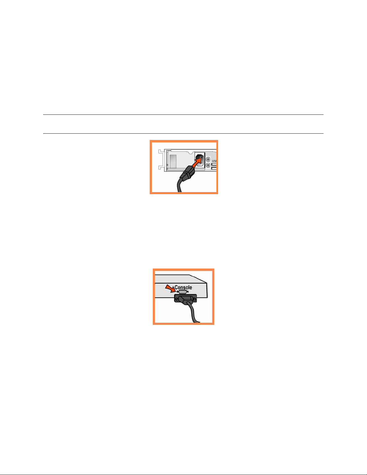
3. Stromanschluss
Wenn Ihr Modell mit einem Hauptnetzschalter (an der Rückseite) ausgestattet ist, schalten Sie diesen
aus.
Stecken Sie das Stromkabel in die CMC und eine Steckdose.
Wenn Ihr Modell mit einem Hauptnetzschalter ausgestattet ist, schalten Sie diesen ein.
Drücken Sie den Systemnetzschalter an der Vorderseite der CMC.
WARNUNG : : In allen europäischen Ländern muss die grün-gelbe Klemme über das Stromkabel geerdet werden.
Ansonsten kann ein elektrischer Stromschlag verursacht werden.
4. Verbinden des CMC-Geräts
Stecken Sie das serielle Kabel in den Konsolenanschluss und ein Terminal ein.
Überprüfen Sie die Einstellungen für den Konsolenanschluss: 9600, 8 Datenbits, keine Parität, 1
Stoppbit, keine Flusssteuerung.
Starten Sie das Terminalemulationsprogramm (z.B. HyperTerminal oder Tera Term Pro).
Geben Sie an der Anmeldeaufforderung admin ein. Das Standardkennwort ist password.
5. Konfigurieren des CMC-Geräts
Der Konfigurations-Assistent wird automatisch gestartet, wenn Sie sich das erste Mal über die CMC-
Befehlszeile anmelden.
Folgen Sie den Anweisungen, um das Netzwerk und die integrierten Schnittstelleneinstellungen für
das CMC-Gerät zu konfigurieren.
Bestätigen Sie die Einstellungen und geben Sie anschließend exit ein, um sich abzumelden.
94 3 - INSTALLING THE CENTRAL MANAGEMENT CONSOLE
Page 95
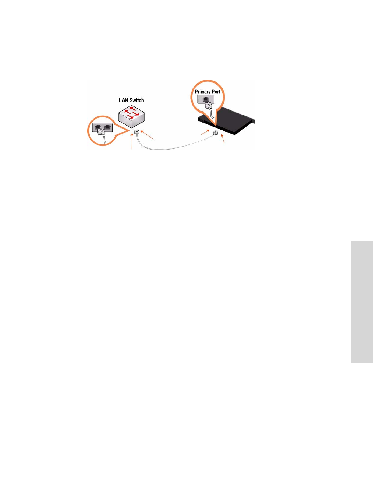
6. Verbinden des CMC-Geräts mit dem Netzwerk
Stecken Sie das Durchgangskabel in den primären Port des CMC-Geräts und des LAN-Switches ein
(hierbei kann es sich um einen beliebigen Port auf dem LAN-Switch handeln, der für die Verbindung
mit einem Host konfiguriert ist)..
7. Überprüfen der Verbindungen
Überprüfen Sie die LED-Statusanzeigen, um sicherzustellen, dass das Gerät richtig angeschlossen ist.
Stellen Sie die Verbindung mit CMC CLI her. Geben Sie an der Eingabeaufforderung folgenden Befehl
ein:
ssh [email protected] oder ssh admin@ipaddress
Geben Sie den Befehl ping ein, um die Verbindungen zu überprüfen. Zum Beispiel:
ping -I <primäre IP-Adresse> <primärer Standardgateway>
8. Verbinden mit der CMC
Geben Sie den URL zur CMC in die Adresszeile des Webbrowsers ein:
http://host.domain oder https://host.domain
Die Willkommensseite der CMC wird angezeigt.
Geben Sie admin im Textfeld Konto ein.
Geben Sie im Textfeld Kennwort Ihr Kennwort ein.
Klicken Sie auf Login (Anmelden), um die Startseite anzuzeigen.
9. Erstellen von Geräteprofilen
Klicken Sie auf Setup Appliances (Geräte konfigurieren), um das Menü zu erweitern.
Klicken Sie auf Profiles (Profile), um die Seite Geräteprofile anzuzeigen.
Erstellen Sie die Profile für die Remotegeräte in Ihrem System.
10. Erstellen von Gerätegruppen
C
ONSOLE
3 INSTALLING THE CENTRAL MANAGEMENT
Klicken Sie auf Geräte konfigurieren, um das Menü zu erweitern.
Klicken Sie auf Gruppen, um die Seite Gerätegruppen anzuzeigen.
Erstellen Sie die Gruppen für die Remotegeräte in Ihrem System.
GETTING STARTED GUIDE 95
Page 96

11. Registrieren der Steelhead-Geräte
Klicken Sie auf Geräte konfigurieren, um die Geräte anzuzeigen: Registrierung, Geräte.
Registrieren Sie die Remotegeräte bei der CMC, wie in der Onlinehilfe beschrieben.
Guide d'Installation rapide de la CMC
Ce chapitre décrit les processus d'installation et de configuration rapides de l'appareil CMC. La console
CMC permet de configurer et de gérer à distance des appareils Steelhead à partir d'un emplacement central.
Pour plus de détails, voir le CD de documentation Riverbed.
1. Mise en route
Veuillez lire les instructions d’utilisation relatives au produit, qui sont situées sur le site http://
www.riverbed.com. Elles contiennent d'importantes informations sur cette version.
Vérifiez sur votre bon de livraison que toutes les pièces nécessaires vous ont bien été livrées.
Vérifiez que vous disposez d'un espace suffisant pour installer l'appareil sur un support de 50 cm à
deux ou quatre montants.
Assurez-vous que la température ambiante ne dépasse pas 35 ºC.
Vous devrez utiliser un tournevis à empreinte cruciforme standard pour monter l'appareil sur un
support.
Vous devrez fournir les informations suivantes :
– Appareil CMC : Hôte et adresse IP
– Réseau : masque de sous-réseau, passerelle par défaut, adresse IP du serveur DNS et nom du
domaine
– Appareils Steelhead distants : adresses IP, noms d'utilisateurs des administrateurs, mots de passe
des administrateurs
2. Montage sur un support
Si votre appareil est doté d'un cadre, veuillez le retirer.
Alignez les trous de vis des brides aux trous de vis du support.
nsérez les vis sur chaque côté de l'appareil et serrez-les.
3. Branchement sur secteur
Si votre modèle est équipé d’un interrupteur d’alimentation principal, mettez-le en position Arrêt
(OFF) (sur le panneau arrière).
Branchez le(s) cordon(s) d’alimentation dans l’appareil CMC et dans une prise secteur.
Si votre modèle est équipé d’un interrupteur d’alimentation principal, appuyez dessus pour le mettre
en position Marche (ON).
96 3 - INSTALLING THE CENTRAL MANAGEMENT CONSOLE
Page 97
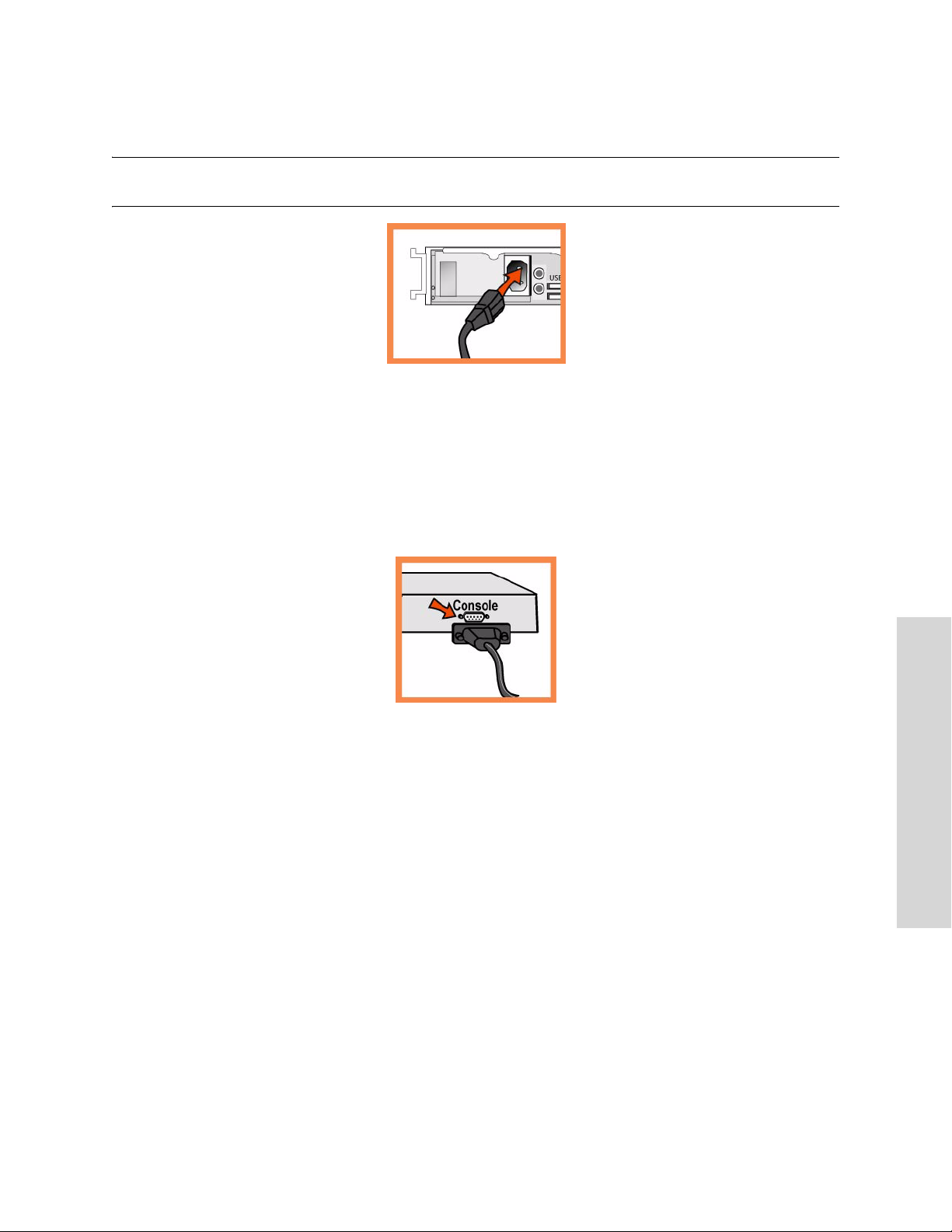
Appuyez sur l’interrupteur d’alimentation système situé à l’avant de l’appareil CMC.
AVERTISSEMENT: Dans toutes les installations électriques en Europe, la fiche jaune/verte du cordon d'alimentation
doit être mise à la terre. En ne mettant pas la fiche jaune/verte à la terre, vous créez un risque de choc électrique..
4. Branchement à l'appareil CMC
Branchez le câble série dans le port Console et à un terminal.
Vérifiez que les paramètres du port Console sont bien les suivants : 9600, 8 bits de données, sans parité,
1 bit d'arrêt, pas de contrôle de flux.
Lancez votre programme d'émulation de terminal (par exemple, HyperTerminal ou Tera Term Pro).
À l'invite, entrez admin. Le mot de passe par défaut est password.
5. Configuration de l'appareil CMC
L'assistant de configuration est automatiquement lancé à la première ouverture de session de
l'interface de ligne de commande.
Suivez les invites pour configurer le réseau et les paramètres de l'interface interne de l'appareil CMC.
Confirmez vos paramètres, puis tapez exit pour quitter le système.
C
ONSOLE
3 INSTALLING THE CENTRAL MANAGEMENT
GETTING STARTED GUIDE 97
Page 98
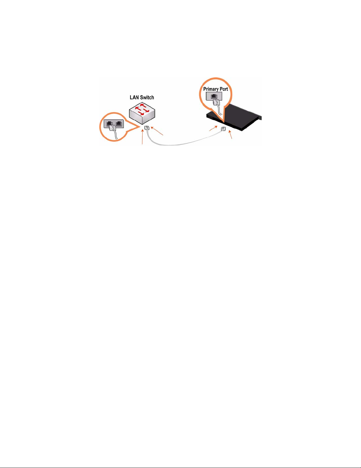
6. Connexion de l'appareil CMC à votre réseau
Branchez une extrémité du câble droit fourni dans le port principal de l'appareil CMC, et l'autre
extrémité dans l'interrupteur LAN (n'importe quel port de votre interrupteur LAN configuré pour la
connexion à un hôte).
7. Vérification des branchements
Pour vous assurer que l'appareil est bien branché, vérifiez que la DEL d'état s'allume.
Connectez-vous à l'interface de ligne de commande de la console CMC. À l'invite du système, entrez la
commande suivante :
ssh [email protected] ou ssh admin@ipaddress
À l'invite du système, entrez des commandes ping pour vérifier que les branchements ont bien été
effectués. Par exemple :
ping -I <adresse-IP-principale> <passerelle-par-défaut-principale>
8. Connexion à la Console CMC
Entrez l'URL de la Console CMC dans la zone d'adresse de votre navigateur Web :
http://hôte.domaine ou https://hôte.domaine
La Console CMC apparaît, et la page de bienvenue est affichée.
Dans la zone de texte dédiée au compte, tapez admin.
Dans la zone de texte réservée au mot de passe, tapez votre mot de passe.
Cliquez sur Login (Ouvrir une session) pour afficher la page d'accueil.
9. Création de profils d'appareil
Cliquez sur Setup Appliances (Configurer des appareils) pour étendre le menu Setup Appliances
(Configuration d'appareils).
Cliquez sur Profiles (Profils) pour afficher la page Appliance Profiles (Profils d'appareils).
Créez des profils pour les types d'appareils distants inclus dans votre système.
10. Création de profils d'appareil
Cliquez sur Setup Appliances (Configurer des appareils) pour étendre le menu Setup Appliances
(Configuration d'appareils).
98 3 - INSTALLING THE CENTRAL MANAGEMENT CONSOLE
Page 99

Cliquez sur Groups (Groupes) pour afficher la page Appliance Groups (Groupes d'appareils).
Créez des groupes pour les types d'appareils distants inclus dans votre système.
11. Enregistrements d'appareils Steelhead
Cliquez sur Setup Appliances (Configurer des appareils) pour afficher la page Setup Appliances
(Configuration d'appareils) : Registration (Enregistrement), Appliances (Appareils).
Enregistrez les appareils distants auprès de la Console CMC, comme décrit dans l'aide en ligne.
Installazione della Central Management Console (CMC)
In questo capitolo viene descritto come installare e configurare rapidamente l'apparecchiatura CMC.
La console CMC consente di configurare e gestire apparecchiature Steelhead remote da una postazione
centrale. Per ulteriori informazioni, consultare il CD della documentazione di Riverbed.
1. Operazioni preliminari
Leggere le note sulla versione del prodotto disponibili all'indirizzo http://www.riverbed.com che
contengono informazioni importanti relative a questa versione specifica.
Verificare che nella confezione siano presenti tutti i componenti necessari.
Assicurarsi di disporre di spazio sufficiente in un rack da 19 pollici a due o quattro montanti
Assicurarsi che la temperatura ambiente non superi 35 ºC.
Assicurarsi di disporre di un cacciavite a croce standard da utilizzare per l'installazione
dell'apparecchiatura nel rack.
Raccogliere le informazioni necessarie:
Apparecchiatura CMC: indirizzo IP e host
Rete: maschera di rete, gateway predefinito, indirizzo IP del DNS e nome del dominio
Apparecchiature Steelhead remote: indirizzi IP, nomi utente amministrativi e password
amministrative
2. Installazione nel rack
Se il modello è dotato di frontalino, rimuoverlo.
Allineare i fori delle viti sulle flangie con quelli sul rack.
Inserire e serrare le viti su entrambi i lati dell'apparecchiatura.
C
ONSOLE
3 INSTALLING THE CENTRAL MANAGEMENT
3. Collegamento dell'alimentazione
Se il modello è dotato di interruttore di alimentazione principale, sul pannello posteriore, verificare che
sia nella posizione off.
Collegare il cavo o i cavi di alimentazione alla console CMC e alla presa di corrente CA.
GETTING STARTED GUIDE 99
Page 100
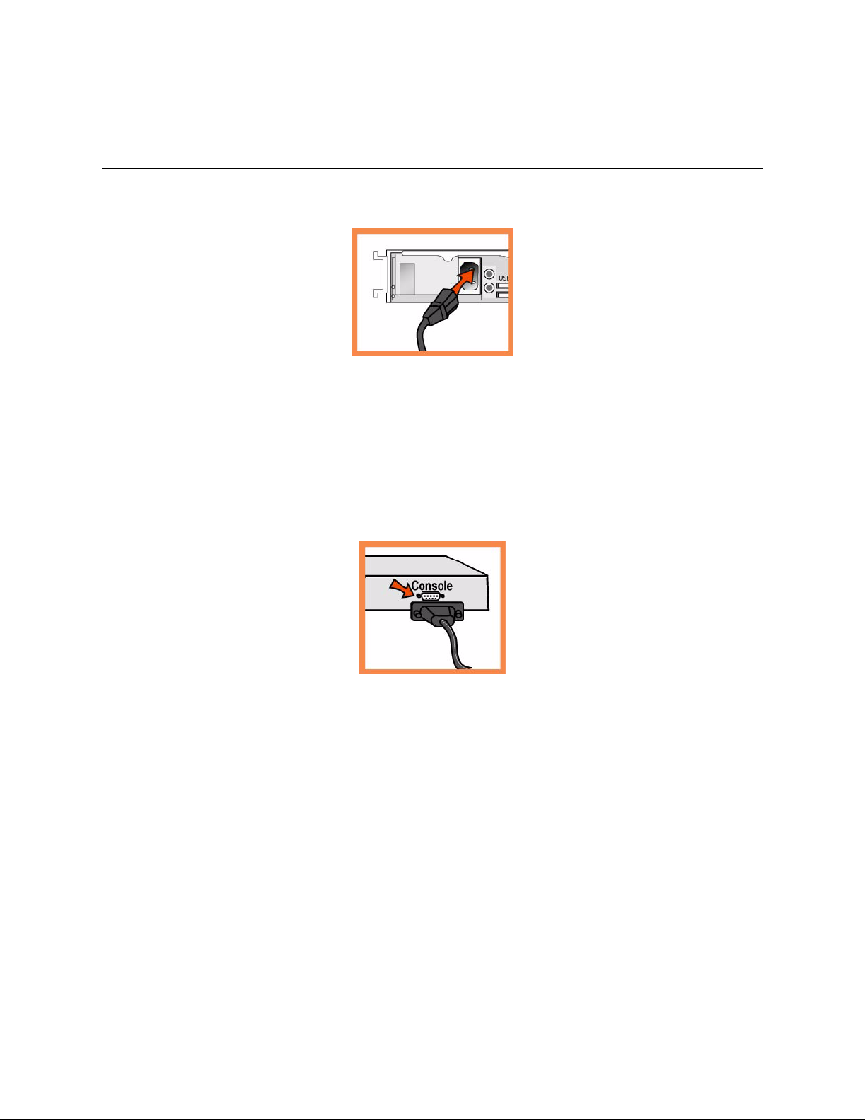
Se il modello è dotato di interruttore di alimentazione principale, premerlo (ON).
Premere l'interruttore di accensione del sistema sul pannello frontale della console CMC.
ATTENZIONE: per le installazioni elettriche in Europa è necessario mettere a terra la linguetta giallo/verde del cavo
di alimentazione per evitare possibili scariche elettriche.
4. Accesso alla console CMC
Collegare il cavo seriale alla porta Console e a un terminale.
Verificare che le impostazioni della porta Console siano: 9600, 8 bit di dati, nessuna parità, 1 bit di stop,
nessun controllo del flusso.
Avviare un programma di emulazione del terminale, ad esempio HyperTerminal o Tera Term Pro.
Al prompt di accesso digitare admin. La password predefinita è password.
5. Configurazione della console CMC
Al primo accesso all'interfaccia da riga di comando della console CMC viene automaticamente avviata
la procedura guidata di configurazione.
Attenersi alle istruzioni per configurare la rete e le impostazioni dell'interfaccia del percorso diretto tra
client e server.
Verificare le impostazioni e quindi digitare exit per uscire dal sistema.
6. Collegamento della console CMC alla rete
Assicurarsi di utilizzare i cavi appropriati per il collegamento alla rete:
Cavi dritti: dalle porte LAN e dalla porta principale allo switch LAN.
Cavo invertito: dalla porta WAN al router WAN.
100 3 - INSTALLING THE CENTRAL MANAGEMENT CONSOLE
 Loading...