

Rittal SK 3303.470, SK 3304.450, SK 3305.470, SK 3305.450, SK 3304.470 Assembly And Operating Instructions Manual
Enclosure cooling unit R1234yf
SK 3303.470
SK 3304.450
SK 3304.470
SK 3305.450
SK 3305.470
Assembly and operating instructions
Downloadmöglichkeiten / Download options / Possibilités de téléchargement
Rittal Blue e enclosure cooling units
Hinweis:
Die Montage-, Installations- und
Bedienungsanleitung ist auch als
Download unter www.rittal.co.jp
verfügbar.
Note:
The assembly and operating in-
structions are available for downloading from www.rittal.co.jp.
注記:
この取扱説明書 ( 組立・設置お
よび運用マニュアル ) は、
www.rittal.co.jp からもダウン
ロードできます。
2 Rittal enclosure cooling unit
Warn- und Sicherheitshinweise / Safety instructions and warnings / Consignes de sécurité
Rittal Blue e enclosure cooling units
Hazards and their prevention according to IEC 60417/ISO 7000/ISO 7010
DE Die Anschlussvorschriften des zuständigen Stromversorgungsunternehmens sind zu beachten. Der Schutzleiter, der Haube und
Chassis verbindet, muss in jedem Fall an beiden Steckern angeschlossen werden. Ansonsten besteht bei einem fehlerhaftem oder defekten Anschluss des Geräts Verletzungsgefahr durch Stromschlag.
EN The connection regulations of the appropriate power supply company are to be followed. The protective conductor between the
hood and the frame must always be attached to both plug connectors. Otherwise, there is risk of injury from electric shock if the connection to the unit is defective or connected incorrectly in any way.
FR Respecter les directives de raccordement du fournisseur d'électricité compétent. La tresse de mise à la masse qui relie le capot au
châssis doit dans tous les cas être raccordée aux deux fiches. Sinon il y a risque de blessure par électrocution en cas de raccordement
erroné ou défectueux de l'appareil.
NL Neem de aansluitvoorschriften van het desbetreffende energiebedrijf in acht. De aarddraad, die de kap en het chassis verbindt, dient
in elk geval op beide connectoren te worden aangesloten. Anders bestaat bij een onjuiste of defecte aansluiting van het apparaat een
risico op letsel door een elektrische schok.
SE Anslutningsföreskrifterna från det ansvariga elförsörjningsföretaget måste följas. Skyddsledaren som förbinder huven och chassit
måste alltid vara ansluten till båda kontakterna. Annars finns risk för skador genom strömstötar vid felaktig eller defekt anslutning av aggregatet.
IT Osservare le prescrizioni relative al collegamento dell’azienda fornitrice di elettricità competente. Il conduttore di protezione che collega la copertura al telaio deve essere sempre collegato su entrambe le estremità. In caso di collegamento assente o errato del dispositivo
vi è il pericolo di lesioni dovute a scossa elettrica.
ES Deben tenerse en cuenta las normas del reglamento electrotécnico de baja tensión. El conductor de protección, que conecta la
cubierta y el chasis, debe estar siempre conectado a ambos conectores. En caso contrario, con una conexión errónea o defectuosa del
aparato, existe un peligro de lesión por descarga eléctrica.
FI Huomioi energiayhtiön liitäntäohjeet. Muussa tapauksessa laitteen virheellinen tai viallinen liitäntä saattaa aiheuttaa sähköiskusta johtuvan loukkaantumisvaaran.
DK Følg altid tilslutningsvejledningen fra det ansvarlige elselskab. Beskyttelseslederen, som forbinder dækslet med chassiset, skal altid
være tilsluttet i begge stik. Hvis ikke dette er tilfældet, er der risiko for at få elektrisk stød som følge af forkert eller defekt tilslutning af
enheden.
IE Ní mór rialacháin nasctha na cuideachta cuí a sholáthraíonn an chumhacht a leanúint. Ní mór go mbeadh an seoltóir cosanta idir an
cochall agus an fráma nasctha leis an dá nascóir plocóide. Mura mbíonn, tá baol gortaithe ó thurraing leictreach má tá an nasc leis an
aonad lochtach nó má tá sé nasctha ar cearr ar bhealach ar bith.
PT Seguir as orientações da respectiva empresa de fornecimento de energia elétrica. O condutor de proteção que interliga a cobertura
com o chassi deve estar sempre conectado em ambas as extremidades. Caso contrário, haverá risco de choque elétrico se a conexão
do aparelho apresentar falha ou estiver incorreta.
HR Potrebno je pridržavati se pravila o priključivanju odgovarajućeg napona isporučitelja električne energije. Zaštitno uzemljenje između
poklopca i okvira mora uvijek s biti spojeno na priključne točke poklopca i okvira. Ukoliko zaštitno uzemljenje nije propisno spojeno ili je
oštećeno, postoji opasnost od ozljeda uzrokovanih strujnim udarom.
MT Għandhom jiġu osservati r-rekwiżiti tat-tqabbid tal-kumpanija tal-provvista tal-elettriku lokali. Il-konduttur protettiv li jqabbad il-hood
max-xażi għandu jkun imqabbad dejjem biż-żewġ plugs. Inkella jkun hemm ir-riskju ta’ xokk elettriku jekk ikun hemm konnessjoni mhux
tajba jew difettuża.
PL Przestrzegać przepisów odpowiedniego Zakładu Energetycznego. Przewód ochronny łączący pokrywę z obudową musi być zawsze
podłączony z obu stron. W przeciwnym razie, w przypadku błędnego lub wadliwego podłączenia urządzenia, istnieje niebezpieczeństwo
porażenia prądem elektrycznym.
CZ Dodržujte předpisy příslušného dodavatele elektrické energie pro připojení elektrického zařízení. V každém případě musí být připojeny oba konektory ochranného vodiče, který spojuje přední plášť jednotky a její rám. Jinak hrozí při chybném nebo vadném připojení
přístroje nebezpečí úrazu elektrickým proudem.
BG Трябва да се спазват предписанията за свързване към захранването на компетентното електроснабдително дружество.
Заземяващият проводник, който свързва капака и рамата, във всички случаи трябва да се свърже към двата конектора. В противен случай съществува опасност от нараняване вследствие на токов удар в случай на неправилно или неизправно свързване
на уреда или неизправна електрическа мрежа.
GR Πρέπει να τηρούνται οι κανονισμοί σύνδεσης της σχετικής εταιρείας παροχής ηλεκτρικού ρεύματος. Ο προστατευτικός αγωγός
μεταξύ του καλύμματος και του πλαισίου πρέπει να συνδέεται πάντα και στις δύο υποδοχές βύσματος. Σε αντίθετη περίπτωση, υπάρχει
κίνδυνος τραυματισμού από ηλεκτροπληξία εάν η σύνδεση της μονάδας είναι ελαττωματική ή εσφαλμένη.
RO Trebuie respectate cerințele de racordare ale companiei locale de alimentare cu energie. Conductorul de protecție dintre capac și
carcasa trebuie să fie conectat întotdeauna la ambele prize. În cazul în care conexiunea aparatului este incorectă sau defectuoasă, există
pericol de rănire prin electrocutare.
Rittal enclosure cooling unit 3
Warn- und Sicherheitshinweise / Safety instructions and warnings / Consignes de sécurité
Rittal Blue e enclosure cooling units
Hazards and their prevention according to IEC 60417/ISO 7000/ISO 7010
HU Az illetékes áramszolgáltató csatlakoztatási előírásait figyelembe kell venni. A burkolatot és a vázat összekötő védővezetéket minden
esetben mindkét csatlakozóhoz csatlakoztatni kell. Ellenkező esetben, a berendezés hibás vagy meghibásodott csatlakoztatása esetén
áramütés veszélye áll fenn.
LT Privalu laikytis atsakingos elektros tiekimo tinklų bendrovės parengtų instrukcijų. Apsauginis laidininkas, jungiantis gaubtą ir korpusą,
visada turi būti prijungtas prie abiejų jungčių. Įrenginio jungties pažeidimo ar defekto atveju kyla pavojus susižaloti gavus elektros smūgį.
EE Järgige vastutava elektrivarustuse ettevõtte vooluvõrku ühendamise eeskirju. Juhtkaitse, mis ühendab katet ja alusraami, peab igal
juhul olema mõlemast pistikust ühendatud. Vastasel korral tekib seadme puudulikul või defektsel ühendamisel vigastusoht elektrilöögi tõttu.
LV Ievērojiet izmantotā elektropiegādes uzņēmuma pieslēguma noteikumus. Starp pārsegu un rāmi esošajam nulles vadam vienmēr ir
jābūt pievienotam abiem elektriskajiem spraudņiem. Pretējā gadījumā, ja iekārtas savienojumā ir radusies kļūme vai ja tā ir pieslēgta nepareizi, pastāv risks ciest no elektriskās strāvas trieciena.
SI Upoštevati je treba predpise za priključevanje naprav pristojnega podjetja za distribucijo električne energije. Ozemljitveni priključek, ki
povezuje pokrov in ohišje, je treba v vsakem primeru namestiti na oba vtiča. V nasprotnem primeru pri napačni priključitvi ali okvarjenem
priključku obstaja nevarnost nastanka poškodb zaradi električnega udara.
SK Treba dbať na predpisy príslušného dodávateľa elektrickej energie týkajúce sa zapojenia. Ochranný vodič, ktorý spája kryt a spodnú
časť zariadenia, musí byť v každom prípade zapojený do oboch zásuviek. V opačnom prípade hrozí pri chybnom alebo nedostatočnom
zapojení zariadenia nebezpečenstvo úrazu elektrickým prúdom.
RU Необходимо соблюдать указания по подключению от компетентного энергопредприятия. Провод заземления, соединяющий кожух и основание, должен быть обязательно подключен с двух сторон. В противном случае при отсутствующем или поврежденном подключении имеется опасность поражения током.
JP 管轄の電力会社の配線規則を守ってください。 カバー ( ユニット前面側ハウジング部 ) とシャーシをつなげる保護接地導線は、
必ず両方のコネクターに接続されていなければなりません。 さもなければ、ユニットの結線に不具合等が生じた場合に、感電によ
り怪我をする危険性があります。
DE Bitte beachten Sie die maximal zulässigen Hebegewichte für Personen. Ggf. ist eine Hebevorrichtung zu verwenden.
EN Please observe the maximum permissible weight to be lifted by one person. Use suitable lifting devices, if needed.
FR Veuillez tenir compte du poids de levage maximal autorisé pour les personnes et le cas échéant utilisez un appareil de levage.
NL Neem het maximaal toegestane tilgewicht voor personen in acht. Gebruik eventueel een hefwerktuig.
SE Observera de maximalt tillåtna lyftvikterna för personer. Vid behov ska en lyftanordning användas.
IT Prestare attenzione ai carichi massimi consentiti per le persone. Se necessario, utilizzare un dispositivo di sollevamento.
ES Rogamos tenga en cuenta el peso máximo permitido que puede levantar una persona. En caso necesario deberá utilizarse un dis-
positivo de elevación.
FI Huomioi sallittu enimmäisnostopaino. Käytä tarvittaessa nostolaitetta.
DK Overhold den maksimalt tilladte løftevægt for personer. Brug en løfteanordning, hvis vægten overskrider den tilladte løftevægt.
IE Cloígh leis an uasmheáchan is ceadmhach do dhuine amháin a chrochadh. Úsáid gairis ardaithe atá oiriúnach, más gá.
PT Por favor, considerar o peso máximo permitido a ser levantado por uma pessoa. Caso necessário, utilizar equipamento adequado.
HR Obratite pažnju na najveću dopuštenu masu koju smije podizati jedna osoba. Ako je potrebno, preporuča se upotreba opreme za
podizanje i premještanje.
MT Jekk jogħġbok innota l-piżijiet ta’ rfigħ massimi permessibbli għan-nies. Jekk ikun hemm bżonn, jeħtieġ li jintuża apparat tal-irfigħ.
PL Prosimy o nieprzekraczanie maksymalnych dopuszczalnych ciężarów podnoszonych przez ludzi. W razie potrzeby należy zastoso-
wać urządzenie podnośnikowe.
CZ Dodržujte maximální přípustné hmotnosti zvedaných břemen stanovené pro osoby. Případně použijte zvedací zařízení.
BG Спазвайте максимално допустимата товароносимост на човек при транспортиране на охладителя. Ако се налага, използ-
вайте подемно устройство.
GR Παρακαλούμε τηρείτε το μέγιστο επιτρεπόμενο βάρος που μπορεί να αρθεί από ένα άτομο. Χρησιμοποιήστε κατάλληλες συσκευές
ανύψωσης, εάν είναι απαραίτητο.
RO Respectați greutățile de ridicare maxim admise pentru o persoana. Dacă este necesar, utilizați dispozitive de ridicare.
HU Vegye figyelembe az egy személy számára maximálisan megengedett emelhető tömegeket. Szükség esetén emelőberendezést kell
használni.
LT Žmonės neturėtų kelti pernelyg sunkaus svorio. Prireikus reikia naudoti kėlimo įrangą.
EE Arvestage inimestele maksimaalselt lubatud tõstekaaludega. Vajaduse korral kasutage tõsteseadeldist.
LV Lūdzu, ievērojiet ierobežojumus attiecībā uz maksimālo svaru, ko ļauts celt vienai personai. Izmantojiet atbilstošas celšanas ierīces,
kad tas ir nepieciešams.
SI Upoštevajte največjo dovoljeno težo, ki jo oseba lahko varno dvigne. Po potrebi uporabite dvižno napravo.
SK Dodržiavajte maximálne limity pre osoby na zdvíhanie bremien. V prípade prekročenia tohto limitu použite zdvíhacie zariadenie.
4 Rittal enclosure cooling unit
Warn- und Sicherheitshinweise / Safety instructions and warnings / Consignes de sécurité
Rittal Blue e enclosure cooling units
Hazards and their prevention according to IEC 60417/ISO 7000/ISO 7010
RU При транспортировке вручную обращайте внимание на максимально допустимый вес. При необходимости используйте
подъемное устройство.
JP 人力のみにより取り扱う最大質量を守ってください。 必要によっては、吊り上げ装置をご使用ください。
DE Das Kühlgerät ist nur standsicher, solange Haube und Chassis miteinander verbunden sind. Sichern Sie daher insbesondere das
Chassis gegen Umfallen, bevor Sie die Haube abnehmen.
EN The cooling unit only stands safely while the hood and chassis are joined to each other. Ensure that the frame, in particular, is secured
against tipping before removing the hood.
FR Le climatiseur est stable uniquement si le capot et le châssis sont reliés entre eux. S'assurer pour cela que le châssis ne puisse pas
tomber avant d'ôter le capot.
NL Het koelaggregaat is alleen stabiel zo lang kap en chassis met elkaar zijn verbonden. Zorg er daarom voor dat als u de kap verwijdert,
het chassis niet kan omvallen.
SE Kylaggregatet står endast stabilt så länge huven och chassit är förbundna med varandra. Säkra därför framför allt chassit så att det
inte välter, innan du tar av huven.
IT Il condizionatore è stabile solo se la copertura e il telaio sono collegati tra loro. Mettere pertanto il telaio in sicurezza da eventuali cadute
prima di rimuovere la copertura.
ES El refrigerador sólo se encuentra suficientemente estable, cuando la cubierta y el chasis se encuentran conectados el uno con el
otro. Por este motivo es importante proteger especialmente el chasis de una caída, antes de retirar la cubierta.
FI Jäähdytin on vakaa vain, kun kehikko ja runko on kiinnitetty toisiinsa. Tue erityisesti runko kaatumisen varalta ennen suojuksen irrottamista.
DK Køleenheden står kun sikkert fast, hvis dækslet og chassiset er forbundet med hinanden. Sørg derfor for at sikre chassiset, så det
ikke vælter, før dækslet tages af.
IE Ní bhíonn an t-aonad fuaraithe ina sheasamh go sábháilte ach amháin nuair atá an cochall agus an fonnadh nasctha le chéile. Cinntigh
go ndaingnítear an fráma, go háirithe, sula mbaintear an cochall de, sa chaoi nach n-iompóidh sé.
PT O condicionador de ar estará fixo apenas quando a cobertura estiver conectada ao chassi. Antes de remover a cobertura, certificarse de que o chassi esteja seguro e não possa tombar.
HR Rashladna jedinica stoji sigurno samo ukoliko su poklopac i kućište međusobno ispravno spojeni. Obratite posebnu pažnju da je
okvir osiguran od prevrtanja prije nego uklanjate poklopac rashladne jedinice.
MT L-unità ta’ tkessiħ hija stabbli biss meta x-xażi u l-hood it-twila jkunu mqabbdin ma’xulxin. Oqgħod attent/a b’mod partikolari li xxażi ma jegħlibx qabel tneħħi l-kappa.
PL Urządzenie jest stabilne tylko wówczas, gdy pokrywa i obudowa są ze sobą połączone. Dlatego przed zdjęciem pokrywy należy
zabezpieczyć obudowę przed przewróceniem się.
CZ Chladicí jednotka je stabilní jen v případě namontovaného pláště na chladicí jednotce. Před sejmutím pláště proto zajistěte samotný
rám jednotky proti převrhnutí.
BG Климатикът е стабилен само когато капакът и рамата са свързани помежду си. Затова укрепете най-вече рамата срещу
падане, преди да свалите капака.
GR Η μονάδα ψύξης στέκεται με ασφάλεια μόνο όταν το κάλυμμα και το πλαίσιο έχουν συνδεθεί μεταξύ τους. Βεβαιωθείτε ότι ειδικά
το πλαίσιο είναι ασφαλισμένο έναντι ανατροπής πριν αφαιρέσετε το κάλυμμα.
RO Aparatul de răcire este stabil numai dacă sunt interconectate capacul și carcasa. În acest scop, asigurați carcasa împotriva căderii,
înainte de a scoate capacul.
HU A hűtőberendezés csak akkor áll biztonságosan, ha a burkolat és a váz egymással össze van kötve. Ezért a vázat biztosítsa eldőlés
ellen, mielőtt a burkolatot leveszi.
LT Šaldymo įrenginys stabilus tol, kol gaubtas sujungtas su korpusu. Todėl prieš nuimdami gaubtą, įsitinkinkite, kad korpusas yra stabilus ir nenukristų.
EE Jahutusseade on kindlalt püsti vaid siis, kui kate ja alusraam on omavahel ühendatud. Kindlustage ümberkukkumise vastu alusraam
enne katte mahavõtmist.
LV Dzesēšanas bloka droša novietošana tiek paveikta pārsegu pienācīgi savienojot ar konstrukciju. Pārliecinieties par to, lai rāmis būtu
pasargāts pret sasvēršanos, pirms pārsega noņemšanas.
SI Hladilna naprava je stabilna, dokler sta pokrov in ohišje klime povezana. Preden snamete pokrov, je zato potrebno ohišje še posebej
zavarovati, da se ne prevrne.
SK Klimatizačné zariadenie je stabilné len vtedy, ak sú kryt a spodná časť spojené. Najmä spodnú časť preto zaistite pred prevrátením
ešte skôr, ako odstránite kryt.
RU Холодильный агрегат устойчив в вертикальном положении, когда кожух и основание соединены между собой. Поэтому
перед удалением кожуха защитите основание агрегата от опрокидывания.
Rittal enclosure cooling unit 5
Warn- und Sicherheitshinweise / Safety instructions and warnings / Consignes de sécurité
Rittal Blue e enclosure cooling units
Hazards and their prevention according to IEC 60417/ISO 7000/ISO 7010
JP カバー ( ユニット前面側ハウジング部 ) がシャーシから取り外されると、クーリングユニットは安定性を失います。カバー ( ユ
ニット前面側ハウジング部 ) を取り外す前に、シャーシが転倒しないように、対策をとってください。
DE Vor dem Abnehmen der Haube muss das Gerät mind. 10 Min. abkühlen, um Verbrennungen an heißen Oberflächen zu vermeiden.
EN Before removing the hood, allow the unit to cool for at least 10 minutes to eliminate the risk of burns from hot surfaces.
FR Avant d'ôter le capot, l'appareil doit refroidir pendant au moins 10 minutes pour éviter les brûlures sur les surfaces brûlantes.
NL Voor het afnemen van de kap dient het apparaat minstens tien minuten af te koelen, zodat u zich niet brandt aan hete oppervlakken.
SE Innan huven tas av måste aggregatet svalna i minst 10 minuter för att undvika att personer bränner sig på heta ytor.
IT Far raffreddare il dispositivo per almeno 10minuti prima di rimuovere la copertura per evitare eventuali ustioni al contatto con le su-
perfici bollenti.
ES El equipo debe haberse enfriado durante un mínimo de 10 minutos antes de proceder a retirar la cubierta, con el fin de evitar quemaduras.
FI Ennen kehikon irrottamista laitteen on annettava jäähtyä vähintään 10 minuuttia, jotta vältetään kuumien pintojen aiheuttamat palovammat.
DK Lad enheden køle af i mindst ti minutter, før dækslet tages af, for at undgå risiko for at brænde sig på varme overflader.
IE Sula mbaintear an cochall de, lig don aonad fuarú ar feadh deich nóiméad ar a laghad chun an baol dó ó dhromchlaí teo a sheachaint.
PT Antes de remover a cobertura, deixar o aparelho arrefecer por no mínimo 10 minutos, para evitar risco de queimadura nas superfícies
quentes.
HR Prije uklanjanja poklopca pričekajte barem 10 minuta da se uređaj ohladi, kako bi se uklonila opasnost od opekotina uzrokovanih
vrućim površinama.
MT Qabel tneħħi l-għatu, l-apparat għandu jitħalla jibred għal mill-inqas 10 min biex tevita ħruq minħabba uċuħ jaħarqu.
PL Przed zdjęciem pokrywy urządzenie musi się chłodzić przez minimum 10 minut, aby nie doszło do poparzenia przez gorące po-
wierzchnie.
CZ Před sejmutím pláště jednotky je nutno nechat chladicí jednotku minimálně 10 minut vychladnout, aby nedošlo k popálení o horké
povrchy.
BG Преди да бъде свален капакът, уредът трябва да се остави да изстине най-малко 10 минути, за да се избегнат изгаряния
от горещите повърхности.
GR Πριν αφαιρέσετε το κάλυμμα, αφήστε τη μονάδα να ψυχθεί για τουλάχιστον 10 λεπτά για να εξαλειφθεί ο κίνδυνος εγκαυμάτων
από καυτές επιφάνειες.
RO Înainte de scoaterea capacului, aparatul trebuie lăsat să se răcească cel puțin 10 min., pentru a evita arsurile cauzate de contactul
cu suprafețele fierbinți.
HU A burkolat levétele előtt a berendezést legalább 10 percig hagyja lehűlni a forró felületek miatti égési sérülések elkerülése érdekében.
LT Prieš nuimdami gaubtą, turite palaukti bent 10 minučių, kol įrenginys atvės, kad nenusidegintumėte prisilietę prie karštų paviršių.
EE Enne katte mahavõtmist peab seade vähemalt 10 minutit jahtuma, et vältida põletusi kuumade pindade tõttu.
LV Pirms pārsega atvēršanas, ļaujiet iekārtai atdzist vismaz 10 minūtes, lai izvairītos no apdedzināšanās riska, ko rada uzkarsušās virs-
mas.
SI Preden snamete pokrov, naj se naprava najmanj 10 minut ohlaja, da se izognete nevarnosti opeklin na vročih površinah.
SK Pred odstránením krytu musí zariadenie minimálne 10 minút chladnúť, inak môže dôjsť k popáleniu na horúcich povrchoch.
RU Перед снятием кожуха дать агрегату остыть в течение ок. 10 мин., во избежание ожога о горячие поверхности.
JP 熱くなっている表面によるやけどを避けるために、カバー ( ユニット前面側ハウジング部 ) を外す前に、ユニットを最低 10 分
間冷ましてください。
DE Gerät nicht in geschlossenen Fahrzeugen transportieren. Kältemittelenthaltende Teile dürfen während der Montage nicht beschädigt
werden. Beschädigte Kühlgeräte dürfen weder in Betrieb genommen noch weiter betrieben werden.Das Gerät darf nicht in Aufstellräumen kleiner 4 m³ installiert werden. Das Gerät sollte nur in Räumen ohne dauernde Zündquelle (z. B. offene Flammen, eingeschaltetes
Gasgerät oder Elektroheizer) aufbewahrt werden. Das Gerät nicht anbohren oder anbrennen. Beachten Sie, dass Kältemittel geruchlos
sind.
6 Rittal enclosure cooling unit
Warn- und Sicherheitshinweise / Safety instructions and warnings / Consignes de sécurité
Rittal Blue e enclosure cooling units
Hazards and their prevention according to IEC 60417/ISO 7000/ISO 7010
EN Do not transport the device in a closed vehicle. Components that contain coolants must not be damaged during assembly. Dam-
aged cooling units must not be put into operation or continue to be used. The device must not be assembled in an installation room
smaller than 4 m³. The device should only be kept in rooms that do not contain continuous sources of ignition (e.g. open flames, powered
gas appliance or electric heater). Do not drill or burn the device. Please note that coolants are odourless.
FR Ne pas transporter l'appareil dans des véhicules fermés. Les pièces contenant du fluide frigorigène ne doivent pas être endommagées durant le montage. Les climatiseurs endommagés ne doivent pas être mis en service ou utilisés. Ne pas installer le climatiseur dans
des pièces de moins de 4m³. Le climatiseur doit être stocké uniquement dans des locaux sans source d'ignition durable (par ex. flammes
nues, appareil à gaz en fonctionnement ou convecteur électrique). Ne pas percer ou brûler le climatiseur. S'assurer que le fluide frigorigène est inodore.
NL Transporteer het koelaggregaat niet in gesloten voertuigen. Koudemiddelhoudende onderdelen mogen tijdens de montage niet beschadigd raken. Beschadigde koelaggregaten mogen niet in bedrijf worden gesteld en niet langer worden gebruikt. Het koelaggregaat
mag niet worden geïnstalleerd in ruimten die kleiner zijn dan 4 m³. Het koelaggregaat mag alleen in ruimten worden opgeslagen zonder
continue ontstekingsbron (bijv. open vuur, ingeschakeld gasapparaat of elektrische verwarming). Boor geen gaten in het koelaggregaat
en stel het niet bloot aan open vuur. Houd er rekening mee dat koudemiddelen reukloos zijn.
SE Transportera inte aggregatet i slutna fordon. Delar som innehåller kylmedel får inte skadas i samband med montage. Skadade kylaggregat får varken tas i drift eller fortsätta användas. Aggregatet får inte installeras i uppställningsrum som är mindre än 4m³. Aggregatet
får endast förvaras i utrymmen där ingen varaktig tändkälla (t.ex. öppen låga, tillkopplad gasbrännare eller elektriskt värmeelement) finns.
Borra eller bränn inte i aggregatet. Tänk på att kylmedel inte luktar.
IT Non trasportare l'apparecchio in veicoli chiusi. Gli elementi contenenti refrigeranti non devono essere danneggiati durante il montaggio. I refrigeranti danneggiati non possono né essere messi in funzione né essere ulteriormente utilizzati. L'apparecchio non deve essere
installato in spazi con una superficie inferiore a 4 m³. L'apparecchio deve essere custodito soltanto in aree prive di fonti di ignizione costanti (ad es. fiamme, apparecchi a gas accesi o apparecchi di riscaldamento elettrici). Non bucare o bruciare l'apparecchio. Si tenga
presente che i refrigeranti sono inodori.
ES No transportar el equipo en vehículos estancos. Las piezas que contienen refrigerante no deben dañarse durante el montaje. Los
refrigeradores dañados no deben seguir funcionando ni ponerse en funcionamiento. El equipo no debe instalarse en espacios de menos
de 4m³. El equipo debe guardarse solo en espacios sin fuentes de ignición continuas (p.ej., llamas abiertas, calefactor eléctrico o aparato de gas encendidos). No perforar ni encender fuego al equipo. Tenga en cuenta que el refrigerante es inodoro.
FI Älä kuljeta laitetta suljetuissa ajoneuvoissa. Kylmäainetta sisältävät osat eivät saa vaurioitua asennuksen aikana. Vaurioituneita jäähdyttimiä ei saa ottaa käyttöön tai jatkaa niiden käyttöä. Laitetta ei saa asentaa tilaan, joka on kooltaan pienempi kuin 4 m³. Laitetta ei saa
säilyttää tiloissa, joissa on jatkuvatoimisia sytytyslähteitä (esim. avotulta, päälle kytkettyä kaasulaitetta tai sähkölämmitintä). Älä poraa tai
polta laitetta. Varmista, että kylmäaine on hajutonta.
DK Enheden må ikke transporteres i lukkede køretøjer. Komponenter indeholdende kølemiddel må ikke beskadiges under montering.
Beskadigede køleenheder må hverken tages i brug eller fortsat være i drift. Enheden må ikke installeres i rum, der er mindre end 4 m³.
Enheden må kun opbevares i rum uden permanent antændelseskilde (f.eks. åben ild, aktiveret gasapparat eller elvarmeapparat). Undlad
at bore i enheden eller udsætte den for åben ild. Vær opmærksom på, at kølemidlet er lugtfrit.
IE Ná hiompar an gléas i bhfeithicil dhúnta. Ná déan damáiste le linn cóimeála do na comhpháirteanna a bhfuil fuaráin iontu. Ná cuir
aonaid fuaraithe atá damáistithe i bhfeidhm agus stop de na haonaid sin a úsáid. Ná déan an gléas a chóimeáil i seomra suiteála atá níos
lú ná 4 m³. Ná coinnigh an gléas ach i seomraí atá saor ó fhoinsí leanúnacha adhainte (m.sh. lasracha oscailte, fearas cumhachtaithe gáis
nó téitheoir leictreach). Ná druileáil agus ná dóigh an gléas. Tabhair faoi deara nach bhfuil aon bholadh ar fhuaráin.
PT Não transportar o aparelho em veículos fechados. As peças que contêm gás refrigerante não devem ser danificadas durante a montagem. Condicionadores de ar danificados não devem ser colocados em funcionamento e sua operação deve ser interrompida. O aparelho não deve ser instalado em ambientes menores que 4 m³. O aparelho somente deve ser armazenado em locais sem fonte de ignição
constante (por exemplo: chama aberta, aparelho de gás ligado ou aquecedor elétrico). Não perfurar o aparelho e não usar chama. Gases
refrigerantes sempre são inodoros.
HR Uređaj ne transportirajte u zatvorenim vozilima. Dijelovi u kojima se nalazi rashladno sredstvo ne smiju se oštetiti tijekom montaže.
Oštećeni rashladni uređaji ne smiju se pustiti u pogon niti dalje upotrebljavati. Uređaj se ne smije instalirati u prostorima manjim od 4 m³.
Uređaj bi se trebao čuvati samo u prostorima bez trajnog izvora zapaljenja (npr. otvoreni plamen, uključeni plinski uređaj ili električni grijač).
Ne bušite i ne palite uređaj. Vodite računa o tome da rashladno sredstvo nema mirisa.
MT Tittrasportax it-tagħmir f’vettura magħluqa. Il-komponenti li fihom fluwidi berrieda m’għandhiex issirilhom ħsara matul l-assemblaġġ.
L-unitajiet tat-tkessiħ bil-ħsara m'għandhomx jibdew jitħaddmu jew ikomplu jintużaw. It-tagħmir m’għandux jiġi assemblat f’kamra ta’
installazzjoni li tkun iżgħar minn 4m³. It-tagħmir għandu jinżamm biss fi kmamar li ma fihomx sorsi kontinwi ta’ tqabbid (eż. fjammi
mikxufin, apparti li jaħdmu bil-gass mixgħulin jew ħiter tal-elettriku). Ittaqqabx jew taħraqx it-tagħmir. Jekk jogħġbok innota li l-fluwidi
berrieda m'għandhomx riħa.
PL Nie transportować urządzenia w zamkniętych pojazdach. Podczas montażu nie wolno uszkodzić części zawierających czynnik
chłodniczy. Uruchamianie i użytkowanie uszkodzonych klimatyzatorów jest zakazane. Urządzenie nie może być instalowane w pomieszczeniach mniejszych niż 4 m³. Urządzenie może być przechowywane wyłącznie w pomieszczeniach, w których nie występują ciągłe źródła zapłonu (np. otwarte płomienie, włączona maszynka gazowa lub ogrzewacz elektryczny). Nie wiercić i nie przypalać urządzenia. Należy pamiętać, że czynnik chłodniczy jest bezwonny.
Rittal enclosure cooling unit 7
Warn- und Sicherheitshinweise / Safety instructions and warnings / Consignes de sécurité
Rittal Blue e enclosure cooling units
Hazards and their prevention according to IEC 60417/ISO 7000/ISO 7010
CZ Nepřepravujte jednotku vuzavřených vozidlech. Díly obsahující chladivo se nesmí během montáže poškodit. Poškozené chladicí jed-
notky se nesmí uvádět do provozu ani dále provozovat. Jednotka se nesmí instalovat vprostorách o objemu menším, než 4m³. Jednotku
byste měli skladovat jen vprostorách bez trvalého zápalného zdroje (např. otevřený plamen, zapnuté plynové zařízení nebo elektrický ohřívač). Do jednotky nevrtejte ani neřežte plamenem. Uvědomte si, že je chladivo bez zápachu.
BG Не транспортирайте устройството в затворени превозни средства. Съдържащите охлаждащо вещество части не трябва
да се повреждат по време на монтажа. Повредени охлаждащи устройства не трябва да се пускат в експлоатация, нито да се
продължава тяхната експлоатация. Устройството не трябва да се инсталира в помещения, по-малки от 4 m³. Устройството
трябва да се съхранява само в помещения без постоянен източник на запалване (напр. открити пламъци, включен газов уред
или електрически нагревател). Не пробивайте и не палете устройството. Уверете се, че охлаждащото вещество е без мирис.
GR Μην μεταφέρετε τη συσκευή σε κλειστά οχήματα. Τα μέρη που περιέχουν ψυκτικό μέσο δεν πρέπει να υποστούν βλάβη κατά τη
συναρμολόγηση. Δεν επιτρέπεται η θέση σε λειτουργία ή η συνέχιση λειτουργίας κατεστραμμένων συσκευών ψύξης. Η συσκευή δεν πρέπει να εγκαθίσταται σε χώρο μικρότερο από 4 m³. Η συσκευή πρέπει να φυλάσσεται μόνο σε χώρους χωρίς μόνιμη πηγή ανάφλεξης (π.χ.
ανοιχτές φλόγες, ενεργοποιημένη συσκευή αερίου ή ηλεκτρική θερμάστρα). Μην τρυπάτε και μην καίτε τη συσκευή. Σημειώστε ότι τα
ψυκτικά μέσα είναι άοσμα.
RO Nu transportați echipamentul în vehicule închise. Componentele care conțin agent de refrigerare nu trebuie să fie deteriorate în timpul
montajului. Echipamentele frigorifice deteriorate nu trebuie puse în funcțiune sau folosite în continuare. Echipamentul nu trebuie instalat
în incaperi mai mici de 4 m³. Echipamentul poate fi păstrat doar în spatii fără surse de foc (de ex. flacără deschisă, aparat cu gaz pornit,
echipament de încălzire electric). Echipamentul nu trebuie găurit sau ars. Atenție, agentul de refrigerare este inodor.
HU A készüléket tilos zárt járműben szállítani. A hűtőközeget tartalmazó elemeket a szerelés közben tilos megrongálni. A megrongálódott hűtőberendezés sem üzembe nem helyezhető, sem tovább nem üzemeltethető. A készüléket tilos 4 m³-nél kisebb felállítási helyiségbe telepíteni. A készüléket kizárólag tartós gyújtóforrás (pl. nyílt láng, bekapcsolt gázkészülék, elektromos fűtőkészülék) nélküli helyiségben szabad tárolni. A készüléket ne fúrja meg vagy égesse meg. Felhívjuk a figyelmét, hogy a hűtőközeg szagtalan.
LT Prietaiso negalima gabenti uždarose transporto priemonėse. Surenkant negalima pažeisti šaldomosios medžiagos turinčių dalių.
Pažeistų aušinimo agregatų negalima nei paleisti, nei toliau naudoti. Prietaiso negalima montuoti mažesnėse nei 4 m³ patalpose. Prietaisas
turėtų būti laikomas tik patalpose be nuolatinio degimo šaltinio (pvz., atviros liepsnos, įjungto dujinio arba elektrinio šildytuvo). Prietaiso
negalima gręžti ar deginti. Atkreipkite dėmesį, kad šaldomosios medžiagos yra bekvapės.
EE Ärge transportige seadet suletud sõidukites. Külmutusagensit sisaldavaid osi ei tohi montaaži käigus kahjustada. Kahjustatud
jahutusseadmeid ei tohi kasutusele võtta ega edasi käitada. Seadet ei tohi paigaldada hoiuruumidesse, mis on väiksemad kui 4 m³. Seadet võib hoida ainult ruumides, kus ei ole süttimisallikat, millest lähtub pidev süttimisoht (nt lahtine tuli, sisselülitatud gaasiseade või elektrikütteseade). Ärge puurige seadmesse avasid või süüdake seda. Jälgige, et külmutusagensid on lõhnavabad.
LV Iekārta nav paredzēta transportēšanai slēgtos transportlīdzekļos. Aukstumaģentus saturošās daļas nedrīkst tikt bojātas montāžas
procesā. Bojātas aukstumiekārtas aizliegts nodot ekspluatācijā, kā arī turpināt izmantot. Iekārtu ir aizliegts uzstādīt telpās, kas mazākas
par 4 m³. Iekārtu atļauts uzglabāt tikai telpās, kur nav pastāvīga aizdegšanās avota (piem., atklātas liesmas, ieslēgtas gāzes iekārtas vai
elektriskā sildītāja). Iekārtu aizliegts urbt un dedzināt. Ņemiet vērā, ka aukstumaģentiem nav smaržas.
SI Naprave ne transportirajte v zaprtih vozilih. Deli, ki vsebujejo hladilno sredstvo, se med montažo ne smejo poškodovati. Poškodovanih
hladilnih naprav ne smete niti zagnati niti uporabljati naprej. Naprave ne smete namestiti v prostorih, ki so manjši od 4m³. Naprava se
lahko shrani samo v prostorih brez stalnih virov vžiga (npr. odprt plamen, vklopljena plinska naprava ali električni grelnik). Vrtanje v napravo
ali vžiganje naprave nista dovoljena. Upoštevajte, da so hladilna sredstva brez vonja.
SK Zariadenie neprepravujte vuzavretých vozidlách. Počas montáže sa nesmú poškodiť diely obsahujúce chladiace médiá. Poškodené
chladiace jednotky sa nesmú uviesť do prevádzky ani prevádzkovať. Zariadenie sa nesmie inštalovať vinštalačných priestoroch menších
ako 4m³. Zariadenie by sa malo uschovávať len vpriestoroch bez stálych zápalných zdrojov (napr. otvorený oheň, zapnuté plynové zariadenie alebo elektrické vykurovacie teleso). Do zariadenia nevŕtajte žiadne otvory anevystavujte ho ohňu. Nezabúdajte, že chladiace
médium je látka bez zápachu.
RU Агрегат транспортировать только в закрытых транспортных средствах. Содержащие хладагент части не должны быть повреждены при монтаже. Поврежденные холодильные агрегаты нельзя запускать в эксплуатацию. Агрегат нельзя устанавливать
в помещениях площадью меньше 4 м³. Агрегат должен храниться только в помещениях без постоянных источников зажигания
(напр. открытый огонь, включенное газовое оборудование или электронагреватель). В агрегате нельзя сверлить отверстия и
нагревать агрегат. Обратите внимание, что хладагент не имеет запаха.
JP ユニットを密閉されている車両で輸送しないでください。設置の際、冷媒が入っている部品が損傷を受けないように注意して
ください。損傷のあるクーリングユニットは、使用しないあるいは、使用し続けないでください。クーリングユニットを 4 m³ よ
り小さい部屋に設置しないでください。ユニットは、継続的な発火源 ( 例えば、裸火、スイッチの入っているガス器具や電気ヒー
ター ) の無い部屋で保管してください。ユニットに誤って穴をあけたり、火をあてたりしないでください。 冷媒が無臭であること
を考慮してください。
8 Rittal enclosure cooling unit
Warn- und Sicherheitshinweise / Safety instructions and warnings / Consignes de sécurité
Rittal Blue e enclosure cooling units
Hazards and their prevention according to IEC 60417/ISO 7000/ISO 7010
DEBrände rund um das Gerät dürfen nicht mit Wasser gelöscht werden. Brandgas kann Fluorwasserstoff enthalten, das in Kontakt mit
Wasser zu Flusssäure reagiert. Für ein geeignetes Löschmittel siehe Kapitel 12 „Safety data sheet“.
EN Should a fire break out around the device, it must not be extinguished using water. Combustion gas may contain hydrogen fluoride,
which reacts to hydrofluoric acid when it comes into contact with water. See Chapter 12 “Safety data sheet” for a suitable extinguishing
agent.
FR Les incendies à proximité du climatiseur ne doivent pas être éteints avec de l'eau. Le gaz issu de l'incendie peut contenir du fluorure
d'hydrogène qui réagit au contact avec l'eau et peut former de l'acide fluorhydrique. Pour utiliser un agent extincteur adapté, voir Chapitre12 «Fiche de sécurité».
NL Vlammen rondom het koelaggregaat mogen niet met water worden geblust. Verbrandingsgas kan waterstoffluoride bevatten dat in
contact met water reageert tot fluorwaterstofzuur. Raadpleeg hoofdstuk 12 „Veiligheidsdatablad“ voor een geschikt blusmiddel.
SE Om en brand uppstår vid aggregatet får den inte släckas med vatten. Brandgas kan innehålla vätefluorid, som vid kontakt med vatten
bildar fluorvätesyra. Lämpliga släckmedel beskrivs i kapitel 12 ”Säkerhetsdatablad”.
IT Non spegnere gli incendi intorno all'apparecchio con l'acqua. I fumi dell'incendio possono contenere fluoruro di idrogeno, che a contatto con l'acqua reagisce diventando acido fluoridrico. Per un agente estinguente adatto, consultare il capitolo 12 "Scheda informativa
in materia di sicurezza".
ES Si se produce un incendio alrededor del equipo, no debe extinguirse con agua. El gas de combustión puede contener fluoruro de
hidrógeno, que reacciona con agua al ácido fluorhídrico. Para obtener información sobre un agente extintor adecuado, consulte el capítulo 12 "Hoja de datos de seguridad".
FI Laitteen ympärillä olevia paloja ei saa sammuttaa vedellä. Palokaasu voi sisältää vetyfluoridia, joka veden kanssa reagoidessaan muodostaa fluorivetyhappoa. Katso soveltuva sammutusaine luvusta 12 ”Turvallisuustietolehti”.
DK Brande rundt om enheden må ikke slukkes med vand. Brandgas kan indeholde hydrogenfluorid, som udvikler flussyre i kontakt med
vand. Se egnede brandslukningsmidler i kapitel 12 "Sikkerhedsdatablad".
IE Dá mbrisfeadh tine amach in aice leis an ngléas, ná húsáid uisce chun í a mhúchadh. D’fhéadfadh fluairíd hidrigine, a chruthaíonn
aigéad hidreafluarach nuair a thagann sí i dteagmháil le huisce, a bheith i ngás dócháin. Féach Caibidil 12 “Bileog sonraí sábháilteachta”
chun faisnéis a fháil faoi ghníomhaí oiriúnach múchta.
PT Não utilizar água para apagar o incêndio no local de instalação do aparelho. O gás gerado em um incêndio pode conter fluoreto de
hidrogênio que, em contato com a água, forma ácido fluorídrico. Para métodos adequados de extinção de incêndio, veja o capítulo 12
“Ficha de dados de segurança”.
HR Požari oko uređaja ne smiju se gasiti vodom. Plin koji nastaje izgaranjem može sadržavati fluorovodik koji u reakciji s vodom daje
fluorovodičnu kiselinu. Podatke o prikladnom sredstvu za gašenje požara potražite u 12. poglavlju „Sigurnosno-tehnički list“.
MT F’każ li jinħakem xi nar qrib it-tagħmir, dan m'għandux jintefa permezz tal-ilma. Il-gass tal-kombustjoni jista’ jkun fih fluworur talidroġenu, li jirreaġixxi għall-aċidu idrofluworiku meta jmiss mal-ilma. Ara l-Kapitolu12 “Skeda ta’ data ta’ sigurtà” għal prodott teffej xieraq.
PL Pożarów w pobliżu urządzenia nie należy gasić wodą. Gazy pożarowe mogą zawierać fluorowodór, który w kontakcie z wodą tworzy
kwas fluorowodorowy. Odpowiedni środek gaśniczy – patrz rozdział 12 „Karta charakterystyki”.
CZ Požár v okolí jednotky se nesmí hasit vodou. Zplodiny hoření mohou obsahovat fluorovodík, který při styku svodou vytváří kyselinu
fluorovodíkovou. Vhodné hasivo viz kapitola 12 „Bezpečnostní list“.
BG Пожари в близост до устройството не трябва да се гасят с вода. Отделящите се при горене газове може да съдържат
флуороводород, който образува флуороводородна киселина при реакция с вода. За подходящо пожарогасително средство
вижте глава 12 „Информационен лист за безопасност“.
GR Τυχόν πυρκαγιά γύρω από τη συσκευή δεν πρέπει να αντιμετωπίζεται με νερό. Το πυροσβεστικό αέριο μπορεί να περιέχει υδροφθόριο, το οποίο αντιδρά με το υδροφθορικό οξύ σε επαφή με το νερό. Για το κατάλληλο πυροσβεστικό μέσο, βλ. κεφάλαιο 12 «Δελτίο
δεδομένων ασφαλείας».
RO Incendiile din jurul echipamentului nu trebuie stinse cu apă. Gazele de ardere pot conține fluorură de hidrogen, care în contact cu
apa reacționează dând acid fluorhidric. Pentru agent de stingere adecvat, a se vedea cap. 12 „Fișa cu date de securitate”.
HU A készülék körüli tüzet vízzel oltani tilos. Az égéstermék fluorgázt tartalmazhat, amely vízzel érintkezve fluorsavvá reagál. A megfelelő
oltóanyagot lásd a 12., „Biztonsági adatlap” c. fejezetben.
LT Gaisrai aplink prietaisą negali būti gesinami vandeniu. Gaisro metu išsiskiriančiose dujose gali būti vandenilio fluorido, kuris reaguodamas su vandeniu sudaro vandenilio fluorido rūgštį. Apie tinkamą gesinimo priemonę skaitykite 12 skyriuje „Saugos duomenų lapas“.
EE Seadme ümber puhkenud tuld ei tohi kustutada veega. Põlemisgaas võib sisaldada fluorvesinikku, mis veega kokku puutudes reageerib ja tekib vesinikflouriidhape. Sobiva lahusti kohta vt ptk 12 „Ohutuskaart”.
LV Ugunsgrēku iekārtas tuvumā nedrīkst dzēst ar ūdeni. Degšanas gāze var saturēt fluorūdeņradi, kas reaģē ar ūdeni un veido fluorūdeņražskābi. Informāciju par piemērotu dzēšanas līdzekli skatiet 12. nodaļā „Drošības datu lapa“.
SI Požarov okrog naprave ne smete gasiti z vodo. Plin lahko pri zgorevanju vsebuje vodikov fluorid, ki v stiku z vodo tvori fluorovodikovo
kislino. Za ustrezno sredstvo za gašenje glejte poglavje 12 – »Varnostni list«.
SK Požiare vokolí zariadenia sa nesmú hasiť vodou. Splodiny horenia môžu obsahovať fluorovodík, ktorý sa pri kontakte svodou mení
na kyselinu fluorovodíkovú. Vhodné hasiace prostriedky sú vymenované vkapitole12 Karty bezpečnostných údajov.
Rittal enclosure cooling unit 9

Warn- und Sicherheitshinweise / Safety instructions and warnings / Consignes de sécurité
Rittal Blue e enclosure cooling units
Hazards and their prevention according to IEC 60417/ISO 7000/ISO 7010
RU Возгорания рядом с агрегатом нельзя тушить водой. Продукты горения могут содержать фтороводород, который при кон-
такте с водой приводит к образованию плавиковой кислоты. Подходящее тушащее средство см. в разделе 12 "Лист данных по
безопасности".
JP ユニット付近の消火に、水を使用しないでください。燃焼ガスにはフッ化水素が含まれている可能性があり、それが水に接触
すると、フッ化水素酸へと反応します。 適切な消火剤に関しては、12 章の「安全データシート」をご覧ください。
DE Der zu kühlende Schaltschrank darf keine zusätzlichen Öffnungen zur Be- und Entlüftung haben. Im Brandfall wird so eine Versorgung des Brandes mit Sauerstoff vermieden.
EN The enclosure to be cooled must not have additional openings for ventilation. This will prevent the supply of oxygen to any potential
fire.
FR L'armoire électrique à climatiser ne doit pas comporter d'ouvertures supplémentaires pour l'aération et la ventilation. En cas d'incendie, il convient d'éviter d'alimenter l'incendie avec de l'oxygène.
NL De te koelen kast mag geen extra openingen voor be- en ontluchting hebben. In geval van brand wordt daardoor voorkomen dat
het vuur met zuurstof wordt gevoed.
SE Apparatskåpet som ska kylas får inte ha några ytterligare öppningar för intag och utsläpp av luft. I händelse av brand undviks på så
sätt att syre tillförs branden.
IT L'armadio di comando da refrigerare non può avere aperture per l'aerazione e la ventilazione aggiuntive. In caso di incendio consente
di non alimentare il fuoco tramite l'ossigeno.
ES El armario de distribución a refrigerar no debe tener aberturas adicionales para ventilación. En caso de incendio, esto evita que el
fuego se alimente con oxígeno.
FI Jäähdytettävässä kytkentäkaapissa ei saa olla muita ilmanvaihtoaukkoja. Näin estetään tulipalon sattuessa tulen hapensaanti.
DK Elektronikskabet, som skal køles, må ikke have ekstra åbninger til luftindsugning og -udsugning. I tilfælde af brand undgår man der-
med, at det tilføres ilt til branden.
IE Ní ceadmhach aon oscailtí breise le haghaidh aeraithe a bheith ag an iniamh. Cuirfidh sé sin cosc ar sholáthar ocsaigine má tharlóidh
tine.
PT O armário a ser refrigerado não deve ter nenhuma abertura adicional para ventilação. Em caso de incêndio, isso evita que o fogo
seja alimentado com oxigênio.
HR Na rasklopnom ormaru koji će se hladiti ne smiju se nalaziti dodatni otvori za prozračivanje odnosno odzračivanje. Time se u slučaju
požara sprečava dovod kisika koji potiče gorenje.
MT L-ispazju li għandu jitkessaħ m’għandux ikollu fetħiet addizzjonali għall-ventilazzjoni. Dan ser jipprevjeni l-provvista tal-ossiġnu għal
kwalunkwe nar potenzjali.
PL Chłodzona szafa sterownicza nie może mieć żadnych dodatkowych otworów wentylacyjnych. Dzięki temu unika się dopływu tlenu
w przypadku pożaru.
CZ V chlazeném rozváděči nesmí být žádné další otvory pro ventilaci a odvětrávání. Vpřípadě požáru je tak zamezeno zásobování požáru kyslíkem.
BG Охлажданият шкаф не трябва да има допълнителни отвори за проветряване и вентилация. По този начин в случай на пожар се предотвратява подхранването на огъня с въздух.
GR Το ηλεκτρικό ερμάριο που ψύχεται από τη συσκευή δεν πρέπει να έχει πρόσθετα ανοίγματα για εξαερισμό. Σε περίπτωση πυρκαγιάς, αποφεύγετε την τροφοδοσία της φωτιάς με οξυγόνο.
RO Tabloul electric care trebuie răcit nu trebuie să aibă deschideri sau aerisire/ventilație. În caz de incendiu, astfel se evită alimentarea
focului cu oxigen.
HU A hűtendő kapcsolószekrény nem rendelkezhet kiegészítő légbeeresztő és légtelenítő nyílással. Tűz esetén így megakadályozható
a tűz oxigénnel való táplálása.
LT Vėsinamoje valdymo spintoje neturi būti jokių papildomų vėdinimo angų. Taip gaisro atveju išvengiama deguonies patekimo į ugnį.
EE Jahutataval lülituskapil ei tohi olla täiendavaid õhutus- ja õhutustamisavasid. Tulekahju korral välditakse nii tule õhutamist hapniku
juurdevoolu abil.
LV Dzesējamajam elektrosadales skapim nedrīkst būt papildu ventilācijas un atgaisošanas atveres. Tādējādi ugunsgrēka gadījumā iespējams izvairīties no skābekļa pieplūdes ugunsgrēka perēklim.
SI Stikalna omara, ki potrebuje hlajenje, ne sme imeti dodatnih odprtin za prezračevanje in odzračevanje. V primeru požara se je treba
izogibati gašenju s kisikom.
SK Skriňový rozvádzač, ktorý chcete ochladzovať, nesmie mať žiadne prídavné otvory na vetranie aodvetrávanie. Pri požiari sa tak zabráni prísunu kyslíka do ohňa.
RU Охлаждаемый шкаф не должен иметь дополнительных отверстий для вентиляции. Таким образом, в случае пожара предотвращается поступление кислорода.
JP 冷却するエンクロージャーには、通気用の開口部を絶対に付け加えないでください。そうすれば、火災の際に酸素が供給され
ることを防ぐことができます。
10 Rittal enclosure cooling unit
Warn- und Sicherheitshinweise / Safety instructions and warnings / Consignes de sécurité
Rittal Blue e enclosure cooling units
Hazards and their prevention according to IEC 60417/ISO 7000/ISO 7010
DE Bei geöffnetem Gerät dürfen keine offenen Flammen oder Zündquellen in der Nähe des Arbeitsplatzes vorhanden sein.
EN When the device is open, no open flames or sources of ignition must be present in the vicinity of the work area.
FR Lorsque le climatiseur est ouvert, aucune flamme nue ou source d'ignition ne doit être présente à proximité du lieu de travail.
NL Bij een geopend koelaggregaat mag geen open vuur en mogen geen ontstekingsbronnen in de buurt van de werkplek aanwezig zijn.
SE När aggregatet är öppet får ingen öppen låga eller tändkällor finnas i närheten av arbetsplatsen.
IT Quando l'apparecchio è aperto, non devono essere presenti fiamme o fonti di ignizione nei pressi dell'area di lavoro.
ES Cuando el equipo está abierto, no debe haber fuego ni fuentes de ignición cerca del lugar de trabajo.
FI Kun laite on auki, työpisteen lähellä ei saa olla avotulta tai sytytyslähteitä.
DK Der må ikke være åben ild eller antændelseskilder i nærheden af arbejdspladsen, når enheden er åbnet.
IE Nuair a bhíonn an gléas oscailte, bíonn cosc ar lasracha oscailte agus ar fhoinsí inadhainte sa limistéar oibre timpeall an ghléis.
PT Quando o aparelho está aberto não deve haver chama aberta ou fonte de ignição perto do local de trabalho.
HR Kada je uređaj otvoren, u blizini radnog mjesta ne smije se nalaziti otvoreni plamen niti izvori zapaljenja.
MT Meta t-tagħmir ikun miftuħ, l-ebda fjamma mikxufa jew sors ta’ tqabbid m'għandu jkun preżenti qrib iż-żona tax-xogħol.
PL Gdy urządzenie jest otwarte, w pobliżu stanowiska pracy nie mogą znajdować się otwarte płomienie lub źródła zapłonu.
CZ Když je jednotka otevřena, nesmí se v blízkosti pracoviště nacházet žádný otevřený oheň ani zápalné zdroje.
BG При отворено устройство не трябва да има открити пламъци или източници на запалване в близост до работното място.
GR Όταν η συσκευή είναι ανοιχτή, δεν πρέπει να υπάρχουν ανοικτές φλόγες ή πηγές ανάφλεξης κοντά στον χώρο εργασίας.
RO Când echipamentul este deschis, nu este permisă prezența focului deschis sau a surselor de foc în apropierea locului de muncă.
HU Nyitott készüléknél nem lehet nyílt láng vagy gyújtóforrás a munkaterület közelében.
LT Kai prietaisas atidarytas, netoli darbo vietos negali būti atviros liepsnos ar degimo šaltinių.
EE Kui seade on avatud, siis ei tohi töökoha läheduses esineda lahtist tuld või süttimisallikaid.
LV Kad iekārta ir atvērta, darba vietas tuvumā nedrīkst būt atklātas liesmas vai aizdegšanās avotu.
SI Ko je naprava odprta, v bližini delovnega mesta ne sme biti odprtega plamena ali virov vžiga.
SK Keď je zariadenie otvorené, nesmú sa vblízkosti pracoviska nachádzať žiadne zdroje otvoreného ohňa ani zápalné zdroje.
RU При открытом агрегате не допускается наличие открытого огня или источников зажигания вблизи рабочего места.
JP ユニットを開けているときは、作業場所の近くに裸火や発火源となるものが無いように注意してください。
DE Verwenden Sie niemals brennbare Flüssigkeiten zur Reinigung des Geräts.
EN Never use flammable liquids for cleaning.
FR Ne jamais utiliser de liquides inflammables pour le nettoyage.
NL Gebruik geen brandbare vloeistoffen voor het reinigen.
SE Använd inga brännbara vätskor för rengöring.
IT Non utilizzare liquidi infiammabili per la pulizia.
ES No utilice líquidos inflamables para realizar la limpieza.
FI Älä käytä puhdistukseen palavia nesteitä.
DK Brug aldrig brændbare væsker til rengøring.
IE Ná húsáid leachtanna inlasta riamh i gcomhair glanta.
PT Nunca utilizar líquidos inflamáveis para efetuar a limpeza.
HR Nikada ne koristite zapaljive tekućine za čišćenje.
MT Tużax likwidi li jieħdu n-nar għat-tindif.
PL Do czyszczenia urządzenia nie stosować łatwopalnych cieczy.
CZ Nepoužívejte k čištění žádné hořlavé kapaliny.
BG Не използвайте запалими течности за почистване.
GR Μη χρησιμοποιείτε ποτέ εύφλεκτα υγρά για τον καθαρισμό.
RO Nu utilizați lichide inflamabile pentru curățare.
HU Tisztításhoz ne használjon gyúlékony folyadékot.
LT Valydami nenaudokite degių skysčių.
EE Ärge kasutage puhastamiseks põlevaid vedelikke.
LV Nekad neizmantojiet uzliesmojošus tīrīšanas līdzekļus.
SI Za čiščenje ne uporabljajte vnetljivih tekočin.
SK Na čistenie nepoužívajte horľavé kvapaliny.
RU Никогда не используйте горючие жидкости для чистки агрегата.
Rittal enclosure cooling unit 11
Warn- und Sicherheitshinweise / Safety instructions and warnings / Consignes de sécurité
Rittal Blue e enclosure cooling units
Hazards and their prevention according to IEC 60417/ISO 7000/ISO 7010
JP ユニットのクリーニングには、絶対に可燃性の液体を使用しないでください。
DE Das Gerät darf nach einem Fall nicht mehr in Betrieb genommen werden.
EN If the device is dropped, it must no longer be put into operation.
FR Le climatiseur ne doit plus être utilisé en cas de chute.
NL Het koelaggregaat mag na een val niet meer worden gebruikt.
SE Om aggregatet fallit får det inte tas i drift igen.
IT In caso di caduta, l'apparecchio non può più essere utilizzato.
ES En el caso de producirse una caída del equipo no debe ponerse en funcionamiento.
FI Laitetta ei saa ottaa enää käyttöön putoamisen jälkeen.
DK Enheden må ikke længere tages i brug efter et fald.
IE Má ligtear don ghléas titim, ná cuir i bhfeidhm a thuilleadh é.
PT Depois de ter sofrido uma queda, o aparelho não deve mais ser colocado em funcionamento.
HR Uređaj se nakon pada više ne smije puštati u rad.
MT Jekk it-tagħmir jitwaqqa’, m’għandux jerġa’ jitħaddem.
PL Nie wolno uruchamiać urządzenia, które uległo upadkowi.
CZ Jednotka se po pádu již nesmí uvádět do provozu.
BG Ако устройството падне, не трябва повече да се използва.
GR Η συσκευή δεν πρέπει να τεθεί σε λειτουργία μετά από πτώση.
RO Daca echipamentul a cazut, a fost trantit, nu va mai fi pus in functiune.
HU A készülék tűzesetet követően többé nem helyezhető üzembe.
LT Nukritus prietaisui, jo nebegalima toliau naudoti.
EE Seadet ei tohi peale tulekahju enam kasutusele võtta.
LV Pēc negadījuma iekārtu vairs nedrīkst izmantot.
SI Če naprava pade, je ne smete več uporabljati.
SK Po páde sa zariadenie nesmie uviesť do prevádzky.
RU После опрокидывания агрегат больше не может быть введен в эксплуатацию.
JP 一度転倒したユニットは決して使用しないでください。
Das Kühlgerät ist ausschließlich zum Kühlen von ge-
DE
schlossenen Schaltschränken vorgesehen. Eine andere Verwendung ist nicht bestimmungsgemäß.
– Das Gerät darf nicht an Orten installiert und betrie-
ben werden, die der allgemeinen Öffentlichkeit (siehe
DIN EN 60335-2-40, Absatz 3.119) zugänglich sind.
The cooling unit is only intended for cooling connected
EN
enclosures. Any other use is not permitted.
– The unit must not be installed and operated in loca-
tions which are accessible to the general public (see
DIN EN 60335-2-40, paragraph 3.119).
– The unit is designed solely for stationary use.
– Das Gerät ist nur für den stationären Betrieb ausge-
legt.
Le climatiseur est exclusivement destiné au refroidisse-
FR
ment d'armoires électriques closes. Toute autre utilisation est non conforme.
– L'appareil ne doit pas être installé et exploité dans
des lieux accessibles au public (voir norme EN
60335-2-40, paragraphe 3.119).
– L'appareil est uniquement destiné à l'exploitation
statique.
Aggregatet är uteslutande avsett för kylning av slutna
SE
apparatskåp. Annan användning räknas som icke avsedd.
– Aggregatet får inte installeras och köras på platser
som är tillgängliga för allmänheten (se DIN EN
60335-2-40, stycke 3.119).
– Aggregatet är konstruerat uteslutande för stationär
drift.
12 Rittal enclosure cooling unit
Het koelaggregaat is uitsluitend bestemd voor het koe-
NL
len van gesloten kasten. Elke andere toepassing wordt
gezien als niet-voorgeschreven gebruik.
– Het apparaat mag niet worden geïnstalleerd op
plaatsen die openbaar (zie DIN EN 60335-2-40, paragraaf 3.119) toegankelijk zijn.
– Het apparaat is alleen geconfigureerd voor stationair
gebruik.
Il condizionatore è progettato esclusivamente per il raf-
IT
freddamento di armadi di comando chiusi. Ogni altro
impiego è da intendersi non conforme alla sua destinazione d’uso.
– L’apparecchio non deve essere installato e utilizzato
in aree accessibili al pubblico (vedere la norma DIN
EN 60335-2-40, paragrafo 3.119).
– L’apparecchio può essere utilizzato solo da fermo.

Warn- und Sicherheitshinweise / Safety instructions and warnings / Consignes de sécurité
Rittal Blue e enclosure cooling units
Hazards and their prevention according to IEC 60417/ISO 7000/ISO 7010
El refrigerador se ha diseñado exclusivamente para la
ES
refrigeración de armarios de distribución cerrados.
Cualquier otro uso no está permitido.
– El equipo no debe ser instalado ni puesto en funcio-
namiento en entornos accesibles al público en general (ver DIN EN 60335-2-40, párrafo 3.119).
– El equipo está diseñado para un funcionamiento es-
tacionario.
Køleenheden er kun beregnet til køling af tilsluttede ind-
DK
kapslinger. Enhver anden brug er ikke tilladt.
– Enheden må ikke installeres eller opereres på lokali-
teter med offentlig adgang (Se DIN EN 60335-2-40,
paragraf 3.119)
– Enheden er udelukkende designet til stationært
brug.
O condicionador de ar está previsto somente para a
PT
refrigeração de armários fechados. Qualquer outro uso
não é apropriado e não é permitido.
– O aparelho não deve ser instalado e operado em lo-
cais acessíveis ao público em geral (consulte a norma DIN EN 60335-2-40, seção 3.119).
– O aparelho foi projetado apenas para o uso em ins-
talação fixa.
It-tagħmir refriġeranti għandu jintuża esklussivament
MT
biex ikessaħ l-armarji magħluqin. Użu ieħor ta' dan
huwa ħażin.
– L-apparat ma għandux jiġi installat u ma għandux
jitħaddem f'postijiet li huma aċċessibbli għallpubbliku (ara DINEN60335-2-40, Paragrafu3.119)
– L-apparat huwa ddisinjat biss għal tħaddim
stazzjonarju.
Chladicí jednotka je určena výhradně k chlazení uza-
CZ
vřených rozváděčových skříní. Jiné použití není použití
v souladu s určením.
– Zařízení se nesmí instalovat a provozovat na mís-
tech, která jsou veřejně přístupná (viz DIN EN 603352-40, oddíl 3.119).
– Zařízení je navrženo jen pro stacionární provoz.
Η μονάδα ψύξης προορίζεται μόνο για την ψύξη συνδε-
GR
δεμένων ερμαρίων. Οποιαδήποτε άλλη χρήση δεν επιτρέπεται.
– Δεν επιτρέπεται η εγκατάσταση και η λειτουργία της
συσκευής σε σημεία, τα οποία είναι προσβάσιμες
στο ευρύ κοινό (δείτε DIN EN 60335-2-40, σημείο
3.119).
– Η συσκευή έχει σχεδιαστεί αποκλειστικά για στατική
χρήση.
A hűtőberendezés kizárólag zárt kapcsolószekrények
HU
hűtésére szolgál. Minden más alkalmazás tilos.
– A berendezést tilos olyan helyre telepíteni és üzemel-
tetni, amely szabadon hozzáférhető laikusok számára (lásd DIN EN 60335-2-40, 3.119 bekezdés).
– A berendezést kizárólag fixen telepítve és álló hely-
zetben szabad telepíteni és üzemeltetni.
Jäähdytysyksikkö on tarkoitettu ainoastaan siihen liitet-
FI
tyjen koteloiden jäähdytykseen. Mikään muu käyttö ei
ole sallittua.
– Laitetta ei saa asentaa ja käyttää yleisessä käytössä
olevissa paikoissa (katso DIN EN 60335-2-40, kohta
3.119).
– Laite on suunniteltu ainoastaan kiinteään käyttöön.
Níl an t-aonad fuaraithe ceaptha ach amháin d’fhuarú
IE
na bhfálta nasctha. Ní cheadaítear d’aon úsáid eile.
– Ná suiteáiltear agus ná oibrítear an t-aonad i
suíomhanna arb inrochtana don phobal i gcoitinne
iad (féach DIN EN 60335-2-40, mír 3.119).
– Is le húsáid dho-aistrithe amháin a dearadh an t-
aonad.
Klima uređaj namjenjen je isključivo hlađenu nanizanih
HR
ormara. Drugačija uporaba nije dozvoljena.
– Uređaj se ne smije instalirati i raditi na mjestima gdje
je dostupan javnosti (DIN EN 60335-2-40, paragraph 3.119)
– Uređaj je namijenjen isključivo za unutarnju upotre-
bu.
To urządzenie jest przewidziane wyłącznie do chłodze-
PL
nia zamkniętych szaf sterowniczych. Każde inne zastosowanie jest niezgodne z przeznaczeniem.
– Urządzenie nie może być instalowane i użytkowane
w miejscach ogólnodostępnych (patrz EN 60335-240, punkt 3.119).
– Urządzenie jest przystosowane wyłącznie do użytko-
wania stacjonarnego.
Охладителното устройство е предназначено само
BG
за охлаждане на кутии и шкафове. Не се разрешава всякаква друга употреба.
– Уредът не трябва да се монтира и работи в мес-
тата, които са достъпни за широката общественост (виж DIN EN 60335-2-40, параграф 3.119).
– Уредът е предназначен единствено за стацио-
нарна употреба.
Climatizorul este conceput doar pentru racirea dulapu-
RO
rilor inchise. Orice alta utilizare nu este permisa.
– Unitatea nu trebuie instalata si folosita in locatii la
care are acces publicul larg. (vezi DIN EN 60335-240, paragraf 3.119)
– Unitatea este proiectata doar pentru utilizare statio-
nara.
Vėsinimo agregatas skirtas naudoti tik specializuotų
LT
duomenų centrų spintų vėsinimui.
– Agregatas negali būti sumontuojamas ir eksplotuoja-
mas viešai prieinamose vietose (pagal DIN EN
60335-2-40, punktas 3.119)
– Prietaisas skirtas tik stacionariam naudojimui.
Rittal enclosure cooling unit 13
Warn- und Sicherheitshinweise / Safety instructions and warnings / Consignes de sécurité
Rittal Blue e enclosure cooling units
Hazards and their prevention according to IEC 60417/ISO 7000/ISO 7010
Jahutusseadmed on ettenähtud jahutamiseks ainult
EE
kilpide/kappide külge monteerituna. Muu laadne kasutus ei ole lubatud.
– Seadmete kasutus üldkasutatavates ruumides ei ole
lubatud (vaata DIN EN 60335-2.40, paragraph
3.119).
– Seade on ettenähtud ainult statsionaarseks paigal-
duseks.
Hladilna naprava je namenjena samo za hlajenje vrstno
SI
povezanih ohišij. Vsaka druga uporaba ni dovoljena.
– Naprava ne sme biti nameščena in delovati na loka-
ciji ki je dostopna širši javnosti (glej DIN EN 60335-240, odstavek 3.119).
– Naprava je namenjena izključno za stacionarno upo-
rabo.
Агрегат следует использовать только для охлаж-
RU
дения распределительных шкафов. Использование в других целях не соответствует его прямому
назначению.
– Агрегат нельзя устанавливать и эксплуатировать
в местах, доступных для постронних лиц (см. DIN
EN 60335-2-40, абзац 3.119)
– Агрегат предназначен для только для стацио-
нарного применения.
Dzesēšanas bloks paredzēts tikai pievienoto sadaļņu
LV
dzesēšanai. Jebkura cita izmantošana nav atļauta.
– Iekārtu nedrīkst uzstādīt un izmantot publiski pieeja-
mās vietās (skatīt standarta DIN EN60335-2-40, paragrāfu 3.119).
– Iekārta ir izstrādāta tikai stacionārai lietošanai.
Chladiaca jednotka je určená výhradne na chladenie
SK
uzavretých rozvádzačových skríň. Iné použitie nie je
prípustné.
– Zariadenie nesmie byť inštalované a používané vo
verejne dostupných priestoroch (viď DIN EN 603352-40, odstavec 3.119).
– Zariadenie je určené na stacionárnu prevádzku.
このクーリングユニットは、閉じられているエンク
JP
ロージャー内の冷却のみを目的として造られていま
す。それ以外の用途は対象外となります。
–
このユニットの、関係者以外の第三者 (公衆) が立
ち入りできる場所での、設置・運用は
ています
– このユニットは、静止状態での運用を前提に設計
されています。
(DIN EN 60335-2-40、項 3.119
、
禁じられ
参照)。
14 Rittal enclosure cooling unit

Contents
Contents
1 Notes on documentation ................ 16
1.1 CE labelling................................................. 16
1.2 Storing the documents................................ 16
1.3 Symbols used in these operating
instructions ................................................. 16
1.4 Other applicable documents ....................... 16
2 Safety notes ................................... 16
3 Device description .......................... 17
3.1 Functional description ................................. 17
3.1.1 How it works ...................................................... 17
3.1.2 Control ............................................................... 18
3.1.3 Bus mode .......................................................... 18
3.1.4 Safety devices .................................................... 18
3.1.5 Condensation ..................................................... 18
3.1.6 Filter mats .......................................................... 18
3.1.7 Door limit switch ................................................. 19
3.1.8 Additional interface X3 ........................................ 19
3.2 Proper use, foreseeable misuse .................. 19
3.3 Scope of supply.......................................... 19
4 Assembly and connection .............. 19
4.1 Choosing the installation site....................... 19
4.2 Notes on assembly ..................................... 20
4.2.1 General .............................................................. 20
4.2.2 Layout of the electronic components in the
enclosure ........................................................... 20
4.3 Fitting the cooling unit ................................. 20
4.3.1 Making the cut-outs ........................................... 21
4.3.2 External mounting of the cooling unit .................. 21
4.3.3 Partial internal mounting of the cooling unit ......... 21
4.3.4 Full internal mounting of the cooling unit ............. 23
4.4 Connecting the condensate discharge ........ 23
4.5 Notes on electrical installation ..................... 24
4.5.1 Connection data ................................................. 24
4.5.2 Overvoltage protection and supply line load ........ 24
4.5.3 Three-phase devices .......................................... 24
4.5.4 Door limit switch ................................................. 24
4.5.5 Notes on the flicker standard .............................. 24
4.5.6 Potential equalisation .......................................... 25
4.6 Making the electrical connection ................. 25
4.6.1 Bus connection (only when interconnecting several
units with a Comfort controller) ........................... 25
4.6.2 Connection X3 for serial interface ....................... 25
4.6.3 Installing the power supply ................................. 26
4.7 Finalising assembly ..................................... 28
4.7.1 Installing the filter media ..................................... 28
4.7.2 Fitting the cooling unit ......................................... 28
4.7.3 Setting the filter mat monitor with the e-Comfort
controller ............................................................ 28
6.1.3 Launching test mode .......................................... 29
6.1.4 General information about programming ............ 30
6.1.5 Editable parameters ........................................... 31
6.1.6 Programming overview ....................................... 32
6.1.7 Defining system messages for evaluation ........... 33
6.1.8 Setting the master/slave identifier ....................... 34
6.1.9 Evaluating system messages .............................. 34
6.1.10 Reset the e-Comfort controller ........................... 36
7 Inspection and maintenance ........... 36
7.1 Compressed air cleaning 3304.xxx,
3305.xxx .................................................... 36
8 Storage and disposal ...................... 40
9 Technical details ............................. 40
9.1 Technical specifications ............................. 40
9.2 Performance diagrams ............................... 43
10 List of spare parts ........................... 44
11 Appendix: Cut-out and hole sizes ... 45
11.1 Dimensions for external mounting .............. 45
11.2 Dimensions for partial internal mounting ..... 45
11.3 Dimensions for full internal mounting .......... 46
12 Safety data sheet ........................... 47
13 Declaration of conformity ................ 74
EN
5 Start-up ......................................... 28
6 Operation ....................................... 29
6.1 Control using the e-Comfort controller ........ 29
6.1.1 Properties ........................................................... 29
6.1.2 Eco mode ........................................................... 29
Rittal enclosure cooling unit 15
1 Notes on documentation
EN
1 Notes on documentation
1.1 CE labelling
Rittal GmbH & Co. KG confirms the conformity of the
cooling unit with the European Union's Machinery Directive 2006/42/EC and EMC Directive 2014/30/EC. A corresponding declaration of conformity has been issued.
This can be found at the end of this document, or on the
Rittal homepage.
1.2 Storing the documents
The assembly and operating instructions as well as all
other applicable documents are an integral part of the
product. They must be issued to everyone who works
with the unit and must always be available and on hand
for operating and maintenance personnel.
1.3 Symbols used in these operating instructions
The following symbols are used in this documentation:
Danger!
A dangerous situation in which failure to
comply with the instructions will result in
death or severe injury.
Warning!
A dangerous situation which may cause
death or serious injury if the instructions
are not followed.
Caution!
A dangerous situation which may lead to
(minor) injuries if the instructions are not
followed.
1.4 Other applicable documents
Assembly and operating instructions in paper and digital
format are available for the unit types described here.
We cannot accept any liability for damage associated
with failure to observe these instructions. Where applicable, the instructions for any accessories used also apply.
2 Safety notes
Please observe the following general safety notes when
transporting, assembling and operating the unit:
– Assembly, installation and servicing may only be per-
formed by properly trained specialists.
– Screw the enclosure to the floor to prevent it from tip-
ping over when the cooling unit is installed.
– Do not obstruct the air inlet and air outlet of the cooling
unit inside and outside the enclosure (see section4.2.2 "Layout of the electronic components in the
enclosure").
– To ensure problem-free opening and closing of the en-
closure door, use a ride-up door roller (refer to the accessories in the Rittal Catalogue). This raises the door
slightly and balances out the weight of the cooling unit,
to prevent buckling of the door and associated seal
problems.
– The heat loss of the components installed in the enclo-
sure must not exceed the useful cooling power of the
cooling unit.
– The cooling units must not be transported in closed
vehicles.
– Cooling units with item numbers: 3303.xxx, 3304.xxx
and 3305.xxx must be transported in an upright position and protected from tipping over.
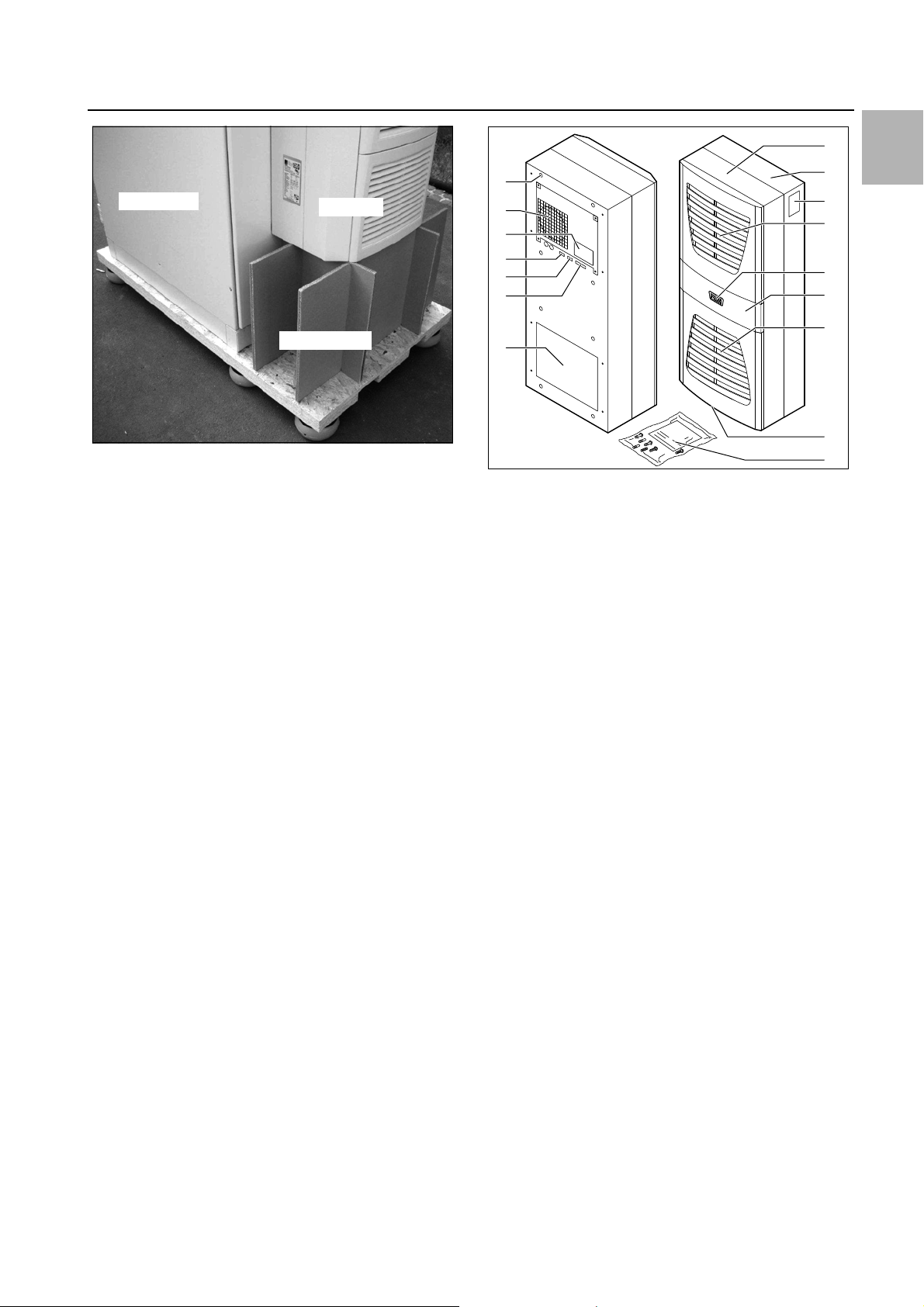
– Shipping braces must be used when transporting a
unit that has already been mounted (on the enclosure).
A wooden structure made from square timbers or
boards to support the cooling unit at the bottom (see
fig. 1) is suitable for this purpose. The pallet should be
big enough to prevent the enclosure and cooling unit
overturning. If the cooling unit is mounted on a door,
ensure the door is kept closed during transport.
Note:
Important notices and indication of situations
which may result in material damage.
Danger!
Extremely flammable gas.
Contains gas under pressure; may explode if heated.
This symbol indicates an "action point" and shows that
you should perform an operation or procedure.
16 Rittal enclosure cooling unit
3 Device description
Enclosure
Support
Cooling unit
10
9
8
11
13
12
16
15
14
1
2
4
5
6
7
3
EN
Fig. 1: Transporting an enclosure/cooling unit combination
– Use only original spare parts and accessories
– Do not make any changes to the cooling unit other
than those described in these instructions or associated instructions.
– Risk of burns! On cooling units with automatic con-
densate evaporation, the surface of the thermal element will get very hot during operation, and will remain
so for some time afterwards.
– The mains connector of the cooling unit must only be
connected and disconnected with the system de-energised. Connect the protective device specified on
the rating plate.
– Risk of chemical burns! Should a fire break out around
the device, it must not be extinguished using water.
Combustion gas may contain hydrogen fluoride,
which reacts to hydrofluoric acid when it comes into
contact with water. See Chapter 12 "Safety data
sheet" for a suitable extinguishing agent.
– Damaged cooling units must not be put into operation
or continue to be used.
– Children and persons with limited cognitive and coor-
dinative capabilities must not operate, service or clean
the device, or use it as a toy.
– Do not drill or burn the device.
– Please note that coolants are odourless.
– Please also observe all of the information on the safety
data sheet for the R1234yf cooling agent used.
3 Device description
Depending on the model chosen, your cooling unit may
vary in appearance from the illustrations contained in
these instructions. However, the functions are identical
in principle.
Fig. 2: Device description
Key
1 Blind rivet nut
2 Evaporator fan
3 Electrical wiring plan
4 X2 master-slave connection
5 X3 optional serial interface
6 X1 terminal strip
7 Air outlet hole
8 Front half of the enclosure
9 Rear half of the enclosure
10 Louvred grille for air outlet
11 Display
12 Infill panel
13 Louvred grille for air inlet
14 Rating plate
15 Condensate discharge
16 Dispatch bag
3.1 Functional description
3.1.1 How it works
The cooling unit (compression refrigeration system)
comprises four main components (see fig. 3): the evaporator (1), the refrigerant compressor (2), the condenser
(3), and the control or expansion valve (4), which are
connected by suitable pipework. This circuit is filled with
a readily boiling substance, the refrigerant. The refrigerant R1234yf (C
tion Potential (ODP) is 0, making it very eco-friendly. A filter dryer (5) which is integrated into the hermetically
sealed cooling circuit provides effective protection
against moisture, acid, dirt particles, and foreign bodies
within the cooling circuit.
) is chlorine-free. Its Ozone Deple-
3H2F4
Rittal enclosure cooling unit 17
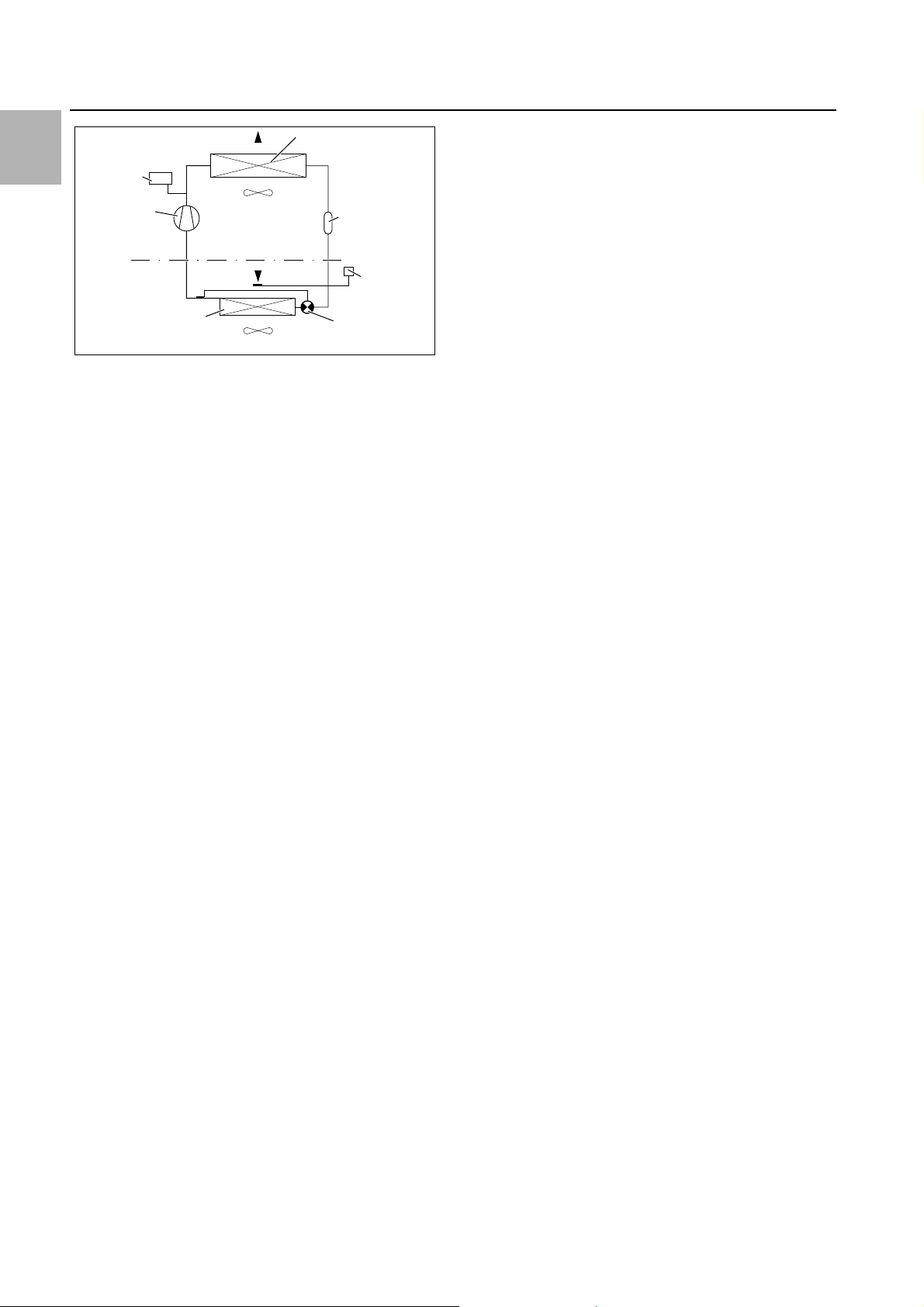
3 Device description
PSAH-
Pressure
switch
Condenser fan
Expansion valve (4)
Temperature
control
Filter dryer (5)
Internal circuit
Compressor (2)
External circuit
Evaporator fan
Evaporator coil (1)
Condenser (3)
EN
Fig. 3: Cooling circuit
In the evaporator coil (1), the liquid refrigerant is converted to a gaseous state. The energy needed for this purpose is taken from the enclosure air in the form of heat,
which has the effect of cooling the enclosure air. In the
compressor (2), the refrigerant is heavily compressed,
so that it achieves a higher temperature inside the condenser (3) than the ambient air. This means that excess
heat may be emitted to the ambient air via the surface of
the condenser, as a result of which the temperature of
the refrigerant drops and it is converted back into liquid.
It is re-injected into the evaporator coil via a thermostatic
expansion valve (4), which causes it to cool down further, and is then once again able to absorb the energy
from the enclosure air in the evaporator coil. The whole
cycle begins again.
3.1.2 Control
The Rittal enclosure cooling units are fitted with an
e-Comfort controller for setting the functions of the cooling unit (see section6 "Operation").
3.1.3 Bus mode
The serial unit interface X2 allows you to create a bus
connection with up to ten cooling units using the masterslave cable (shielded, four-wire cable, Model No.
3124.100). This allows you to implement the following
functions:
– Parallel unit control (the cooling units in the network
– Parallel door status message ("door open")
– Parallel collective fault message
Data is exchanged via the master-slave connection.
During commissioning, assign an address to each unit
that also includes the identifier "master" or "slave".
3.1.4 Safety devices
– In the cooling cycle, the cooling units have a tested
– Temperature monitoring prevents the evaporator coil
18 Rittal enclosure cooling unit
can be switched on and off simultaneously)
pressure switch to EN 12 263 which is set to maximum PS (permissible pressure); this operates via an
automatic reset device whenever the pressure drops
again
from icing over. If there is a risk of icing, the compres-
sor switches itself off and automatically switches itself
back on again at higher temperatures
– The refrigerant compressor and the fans are equipped
with thermal winding shields to protect against excess
current and excess temperatures
– In order to allow a reduction of pressure inside the
compressor and hence a safe restart, once it has been
switched off (e.g. upon reaching the set temperature
via the door limit switch function or via de-energising),
the device will switch back on with a delay of 180 seconds
– The device has floating contacts on the connection
pins (terminals 3 – 5), via which system messages
from the device may be polled, e.g. using a PLC (1 x
change-over contact Basic controller, 2 x normally
open contacts e-Comfort controller)
3.1.5 Condensation
At high levels of humidity and low temperatures inside
the enclosure, condensation may form on the evaporator coil.
The cooling units (except 3303.xxx) have automatic,
electric condensate evaporation. The thermal component used for this purpose is based on self-regulating
PTC technology. Condensate arising on the evaporator
coil is collected in a tank in the external circuit of the
cooling unit, and partially evaporated via the airflow.
When the water level rises, the water enters the PTC
thermal component and is evaporated (through-flow
heater principle). The water vapour streams out of the
cooling unit with the airflow from the external fan.
The PTC thermal component is permanently connected
and has no switchpoint. It is protected against short-circuits with miniature fuses (F1.1, F1.2). If the fuse has
tripped, any condensation is drained off via the safety
overflow.
For unit types 3303.xxx, the condensate is routed
downwards out of the unit via a drain pipe on the evaporator coil divider panel. For this purpose, a hose must
be connected to the condensate nozzle (see section4.4
"Connecting the condensate discharge"). External condensate evaporators are available as accessories for
these unit types (refer also to the accessories in the Rittal
Catalogue).
3.1.6 Filter mats
The entire cooling unit condenser is covered with a dirtrepelling, easy-to-clean RiNano coating. In many applications, therefore, the use of filter media is unnecessary,
particularly with dry dusts.
For dry, coarse dust and lint in the ambient air, we recommend installing an additional PU foam filter mat (available as an accessory) in the cooling unit. Depending on
the incidence of dust, you will need to replace the filter
mat from time to time.
For air containing oil condensate, we recommend the
use of metal filters (also available as an accessory).
4 Assembly and connection
These may be cleaned with suitable detergents and reused.
Function of the filter mat monitor:
Dirt on the filter mat is automatically determined by
measuring the temperature difference in the external circuit of the cooling unit. As the level of filter mat soiling increases, the temperature difference will increase. The
setpoint value of the temperature difference in the external circuit adapts automatically to the relevant operating
points in the performance diagrams. Hence there is no
need to readjust the setpoint value for different unit operating points.
3.1.7 Door limit switch
The cooling unit may be operated with a floating door
limit switch connected. The door limit switch is not included with the supply (available as an accessory, Model
No. 4127.010).
The door limit switch function causes the fans and the
compressor in the cooling unit to be switched off after
approximately 15 seconds when the enclosure door is
opened (contacts 1 and 2 closed). This prevents the formation of condensation inside the enclosure while the
enclosure door is open. In order to prevent damage to
the unit, it is equipped with an ON delay: The evaporator
fan cuts back in with a delay of approximately 15 seconds after the door has been closed, while the condenser fan and compressor switch on after approximately
3minutes.
Note:
– No external voltage may be applied to the
door contacts (terminals 1 and 2).
– For cooling units with basic control, the
evaporator fan continues to run even
when the door is open.
3.1.8 Additional interface X3
Note:
The electrical signals at the interface are of
an extra-low voltage (not extra-low safety
voltages to EN 60 335).
The cooling unit is state of the art and built according to
recognised safety regulations. Nevertheless, improper
use can pose a threat to the life and limb of the user or
third parties, or result in possible damage to the system
and other property.
Consequently, the cooling unit must only be used properly and in a technically sound condition! Any malfunctions which impair safety should be rectified immediately.
Proper use also includes the observance of the documentation provided, and compliance with the inspection
and maintenance conditions.
Rittal GmbH & Co. KG is not liable for any damage which
may result from failure to comply with the documentation provided. The same applies to failure to comply with
the valid documentation for any accessories used.
Inappropriate use may be dangerous. Examples of inappropriate include:
– Use of the cooling unit over long periods with the en-
closure open.
– Improper operation.
– Improper rectification of malfunctions.
– Use of accessories not approved by Rittal GmbH &
Co. KG.
3.3 Scope of supply
The unit is supplied in a packaging unit in a fully assembled state.
Please check the scope of supply for completeness.
Qty. Description
1 Enclosure cooling unit
1
1
1
1
4 – 10
Dispatch bag:
– Assembly and operating instructions
– Self-adhesive tape
– Connector X1
– Grub screws
– Nuts, washers
EN
An additional interface card may be connected to the 9pole SUB-D connector X3 in order to incorporate the
cooling unit into higher-level monitoring systems (available as an accessory, interface card Model No.
3124.200).
1 Drilling template
Tab. 1: Scope of supply
4 Assembly and connection
4.1 Choosing the installation site
3.2 Proper use, foreseeable misuse
The cooling unit is only intended for cooling connected
enclosures. Any other use is not permitted.
– The unit must not be installed and operated in loca-
tions which are accessible to the general public (see
DIN EN 60335-2-40, paragraph 3.119).
– The unit is designed solely for stationary use.
Rittal enclosure cooling unit 19
When choosing the installation site for the enclosure,
please observe the following:
– The site for the enclosure, and hence the arrangement
of the cooling unit, must be carefully selected so as to
ensure good ventilation (clearance between units and
clearance between the unit and the wall must be at
least 200 mm in each case).
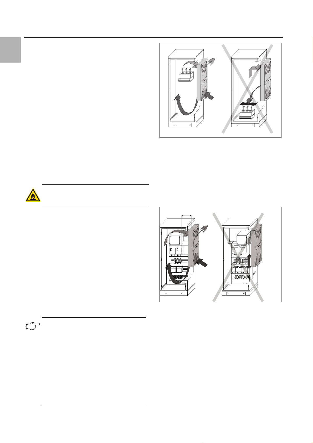
EN
x
4 Assembly and connection
– The cooling unit must be installed and operated in a
vertical position (maximum deviation: 2°).
– The SK 33xx.xxx devices must not be assembled in in-
stallation rooms smaller than 4 m³.
– The installation site must be free from excessive dirt,
aggressive ambient conditions and moisture.
– The ambient temperature must be within the limits
specified on the rating plate.
– It must be possible to fit a condensate discharge (see
section4.4 "Connecting the condensate discharge").
– The mains connection data as stated on the rating
plate of the unit must be guaranteed.
– The enclosure to be cooled must not have additional
openings for ventilation. This will prevent the supply of
oxygen to any potential fire.
– The device should only be kept in rooms that do not
contain continuous sources of ignition (e.g. open
flames, powered gas appliance or electric heater).
4.2 Notes on assembly
4.2.1 General
Caution!
The cooling circuit contains volatile,
flammable gases.
Fig. 4: Never direct the cold airflow at active components
Air diversion components are available as accessories –
please refer to the Rittal Catalogue.
It is important to ensure even air circulation inside the enclosure. Under no circumstances should air inlet and
outlet openings be obstructed, otherwise the cooling
performance of the unit will be reduced. Ensure the distance "x" (see fig. 5) from components and other installed enclosures so that the required air circulation is
not obstructed and prevented.
– Check the packaging carefully for signs of damage.
Traces of oil on damaged packaging are an indication
of refrigerant loss and leakages. Any packaging damage may be the cause of a subsequent functional failure.
– The enclosure must be sealed on all sides (IP 54). In-
creased condensation will occur if the enclosure is not
airtight.
– In order to avoid excessive condensation inside the
enclosure, we recommend installing a door limit
switch (e.g. 4127.010) which deactivates the cooling
unit when the enclosure door is opened (see section3.1.7 "Door limit switch").
4.2.2 Layout of the electronic components in the enclosure
Note:
Risk of condensation!
When arranging the electronic components
inside the enclosure, please ensure that the
cold airflow from the cooling unit is not directed at active components. Please also
ensure that the cold airflow is not directed at
the warm exhaust airflow from active components such as converters. This may lead
to an air short-circuit and therefore prevent
adequate climate control, or may even
cause the cooling unit’s internal safety devices to cease cooling operation.
Fig. 5: Air circulation inside the enclosure
4.3 Fitting the cooling unit
The enclosure cooling unit may optionally be externally
mounted on the enclosure (1), partially internally mounted (2) or fully internally mounted (3):
20 Rittal enclosure cooling unit
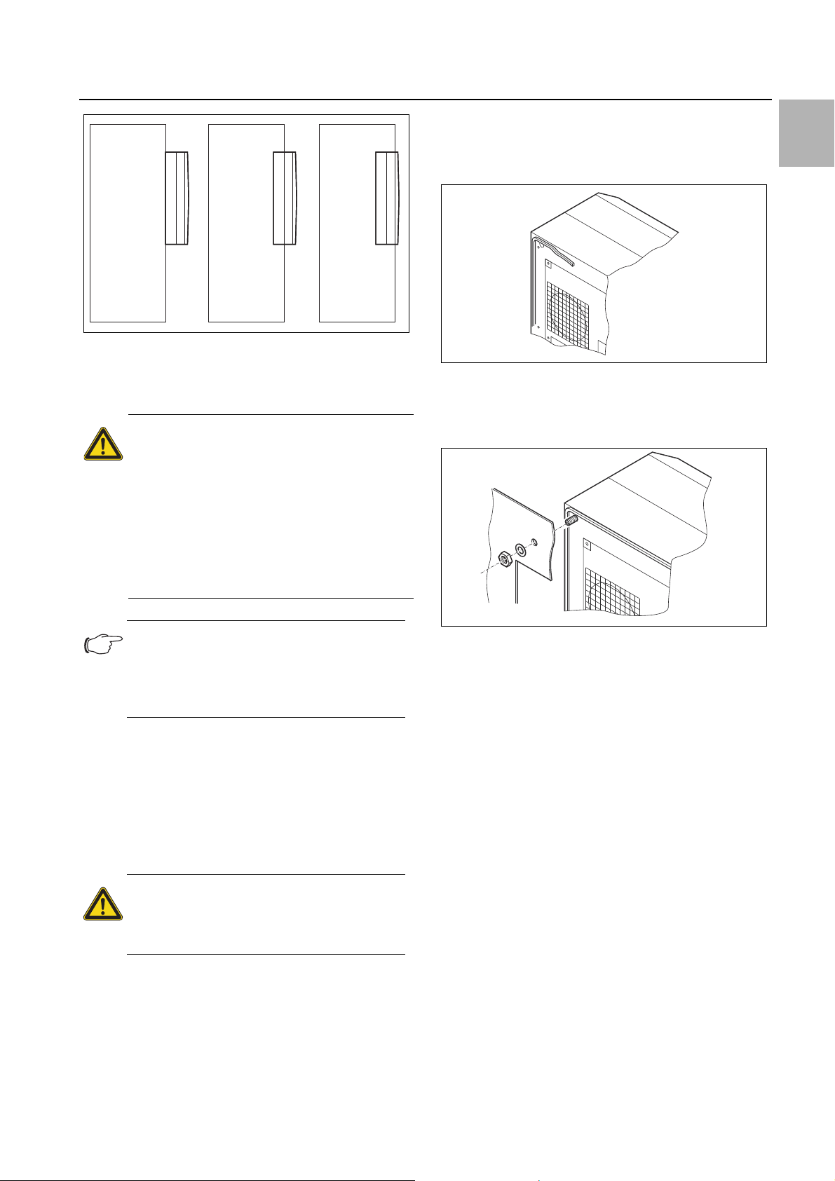
Fig. 6: Installation method
123
To this end, cut the side panel or door of the enclosure
as per the drilling template included with the supply, and
drill the relevant holes.
Caution!
Ensure that components containing
coolants do not get damaged during
assembly.
When the device is open, ensure there
are no open flames or sources of ignition in the vicinity of the work area.
When assembling the device, use per-
sonal protective equipment consisting
of at least gloves and safety goggles.
4 Assembly and connection
4.3.2 External mounting of the cooling unit
Cut the supplied sealing tape to the correct length and
stick it carefully along the back of the unit so that no
gaps are left at the joints.
Fig. 7: Applying the self-adhesive tape
Screw the supplied grub screws into the blind nuts on
the rear of the unit.
Secure the unit using the supplied washers and nuts.
EN
Note:
For high dynamic loads and mounting on
the enclosure door, we recommend using
reinforced door hinges 8800.710 (see Rittal
Catalogue).
4.3.1 Making the cut-outs
Affix the supplied drilling template to the side panel or
door of the enclosure using adhesive tape.
There are dimensioning lines on the drilling template to
suit the various installation options for your cooling unit.
Using the dimension drawings (see Appendix), identify
the valid lines and dimensions for your installation type
on the drilling template.
Caution!
Carefully deburr all drilled holes and
cut-outs to prevent injuries caused by
sharp edges.
Mark, drill and deburr the holes.
Make the cut-outs including the line width as per the
drilling template.
Deburr the cut-outs.
Fig. 8: Securing the cooling unit
4.3.3 Partial internal mounting of the cooling unit
Carefully remove the louvred grille and, where applica-
ble, the infill panel, from the enclosure by pulling forwards.
Carefully disconnect the connector from the rear of the
display and gently push it inwards through the cable
gland.
Rittal enclosure cooling unit 21
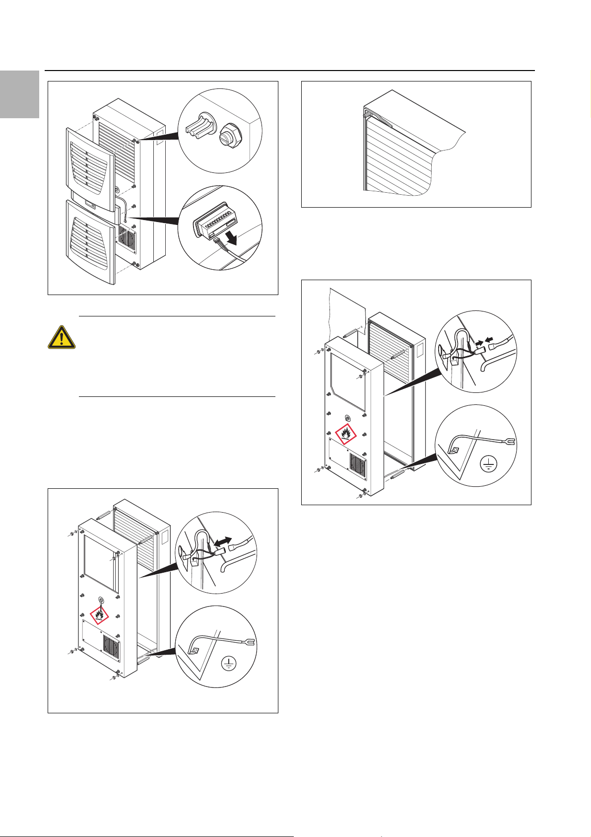
EN
4 Assembly and connection
Fig. 11: Applying the self-adhesive tape
Push the rear enclosure half into the mounting cut-out
and secure it with the four spacer bolts.
Push the display cable through the cable gland of the
front enclosure half.
Fig. 9: Removing the louvred grille & disconnecting the display
Caution!
Stability of the cooling unit is only guar-
anteed in its assembled state. Brace
the rear half of the enclosure to prevent
it from falling over before removing the
front half.
Loosen the four nuts on the front half of the enclosure
and pull the enclosure forwards by approx. 5 cm.
Loosen the flat-pin connectors of the PE conductor
between the two enclosure halves.
Disconnect the fan connection.
Remove the front enclosure tray completely.
Fig. 12: Securing the cooling unit
Connect the fan connector and PE conductor.
Mount the front enclosure tray using the washers and
nuts.
Fig. 10: Removing the cover
Remove the four spacer bolts.
Cut the supplied sealing tape to the correct length and
stick it carefully along the inside of the rear enclosure
half so that no gaps are left at the connection points.
22 Rittal enclosure cooling unit
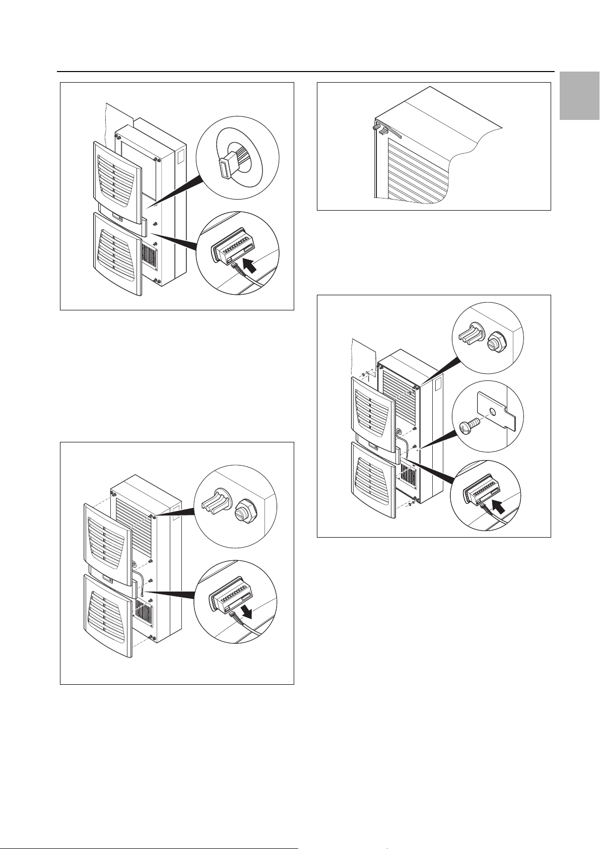
Fig. 13: Connecting the display connector
Carefully connect the display connector.
Push the louvred grille and, where applicable, the infill
panel, onto the enclosure.
4 Assembly and connection
EN
Fig. 15: Applying the self-adhesive tape
Loosen the four nuts and washers from the front en-
closure half.
Push the unit into the mounting cut-out from the inside
of the enclosure, and secure it to the enclosure from
the outside using the washers and nuts.
4.3.4 Full internal mounting of the cooling unit
Carefully remove the louvred grille and the infill panel
from the enclosure by pulling forwards.
Carefully disconnect the connector from the rear of the
display.
Fig. 14: Removing the louvred grille & disconnecting the display
Cut the supplied sealing tape to the correct length and
stick it carefully along the front enclosure half so that
no gaps are left at the connection points.
Fig. 16: Securing the cooling unit
Where necessary, additionally secure the unit using
the supplied mounting plates as shown in fig. 16.
Carefully connect the display connector.
Push the louvred grille and, where applicable, the infill
panel, onto the enclosure.
4.4 Connecting the condensate discharge
A condensate discharge hose can be fitted to all types
of cooling unit.
The condensate discharge
– must be laid with a suitable and constant gradient (no
siphoning)
– must be laid without kinks
– must not have a reduced cross-section if extended
The condensate hose is available as an accessory (refer
also to Accessories in the Rittal Catalogue).
Rittal enclosure cooling unit 23

EN
4 Assembly and connection
Fig. 17: Connecting the condensate discharge
Connect a suitable hose to the condensate nozzle and
secure using a hose clip.
Route the condensate hose to a drain or into the ex-
ternal condensate evaporator (refer to Accessories in
the Rittal Catalogue).
4.5 Notes on electrical installation
When performing the electrical installation, it is important
to observe all valid national and regional regulations as
well as the provisions of the responsible power supply
company. The electrical installation may only be carried
out by a qualified electrician who is responsible for compliance with the applicable standards and regulations.
4.5.1 Connection data
– The connected voltage and frequency must corre-
spond to the values stated on the rating plate
– The cooling unit must be connected to the mains via
an all-pin isolating device, which ensures at least
3 mm contact opening when switched off
– No additional temperature control may be connected
upstream of the unit at the supply end
– Install the protective device specified on the rating
plate to protect the line and equipment from short-circuits.
– The mains connection must ensure low-noise poten-
tial equalisation
4.5.2 Overvoltage protection and supply line load
– The unit does not have its own overvoltage protection.
Measures must be taken by the operator at the supply
end to ensure effective lightning and overvoltage protection. The mains voltage must not exceed a tolerance of ±10%.
– In accordance with IEC 61 000-3-11, the unit is in-
tended solely for use at sites with a continuous current-carrying capacity (incoming mains power supply)
of more than 100 A per phase and with a supply voltage of 400/230 V. If necessary, the electricity supply
company must be consulted to ensure that the continuous current-carrying capacity at the point of connection to the public grid is sufficient for connection of
such a unit.
– The fans and compressors in single- and three-phase
units are intrinsically safe (thermal winding protection).
– Install the protective device specified on the rating
plate to protect the line and equipment from short-circuits (miniature circuit-breaker with appropriate characteristic – e.g. "K" characteristic – or gG standard
type slow fuse, circuit-breaker for plant or transformer
protection). Select a suitable circuit-breaker in accordance with the information specified on the rating plate:
Set it to the minimum specified value. This will achieve
the best short-circuit protection for cables and equipment. Example: Specified setting range 6.3 – 10 A; set
to 6.3 A.
4.5.3 Three-phase devices
– The electrical connection for devices in the three-
phase version MUST be made with a clockwise rotating field
– The three-phase version of models 3304.xxx and
3305.xxx must be connected to a TN network with
star earthing via a circuit-breaker for plant protection
(current setting as per the rating plate). Three-phase
units with special voltages must be protected with a
circuit-breaker for transformer protection (category
AC-3) as per the rating plate.
– Units designed for three phase 400/460 V feature ad-
ditional monitoring of the rotary field or the absence of
a phase. If the rotary field is incorrect or a phase is absent, the unit will not run.
4.5.4 Door limit switch
– Each door limit switch must only be assigned to one
cooling unit.
– Several door limit switches may be connected in par-
allel to one cooling unit.
– The minimum cross-section for the connection cable
is 0.3 mm
– The line resistance to the door limit switch must not
exceed a maximum of 50 Ω.
– The door limit switch only supports a floating connec-
tion; no external voltages.
– The contact of the door limit switch must be closed
when the door is open.
The safety extra-low voltage for the door limit switch is
provided by the internal power pack: Current approx.
30 mA DC.
Connect the door limit switch to terminals 1 and 2 of
the connector.
4.5.5 Notes on the flicker standard
The flicker limits specified in standard EN 61 000-3-3 or
-3-11 are adhered to, provided the supply impedance is
less than approx. 1.5 Ω.
Where necessary, the unit operator should measure the
connected impedance or consult the responsible electricity supply company. If there is no way of influencing
the supply impedance and sensitive installed components (e.g. BUS) are subjected to interference, a line reactor or starting-current limiting device should be con-
2
for a cable length of 2 m.
24 Rittal enclosure cooling unit

nected upstream of the cooling unit to restrict the startup current of the cooling unit.
4.5.6 Potential equalisation
If, for EMC reasons, the unit is to be integrated into the
customer’s existing potential equalisation system, a
conductor with a larger nominal cross-section can be
connected to the potential equalisation connection point
(attachment points) on the wall-mounted cooling units.
According to the standard, the PE conductor in the
mains connection cable is not classified as an equipotential bonding conductor.
4.6 Making the electrical connection
4.6.1 Bus connection (only when interconnecting several units with a Comfort controller)
When using several cooling units, the serial device interface X2 can be used to connect up to ten cooling units
with the bus cable (Model No. 3124.100).
Note:
The electrical signals at the X2 interface are
of an extra-low voltage (not extra-low safety
voltages in accordance with EN 60 335-1).
4 Assembly and connection
EN
When interconnecting, please note the following:
– De-energise the cooling units to be connected
– Ensure proper electrical insulation
– Make sure the cables are not laid in parallel to power
lines
– Make sure that the lines are short
Note:
With the last slave unit in the group, do not,
under any circumstances, connect the remaining socket of the Y cable 3124.100 into
interface X3 of the cooling unit!
4.6.2 Connection X3 for serial interface
The interface card (Model No. 3124.200) may be connected to X3. This is used to evaluate system messages
in a PLC, for remotely setting parameters and monitoring, or for integration into the facility management system.
Rittal enclosure cooling unit 25

EN
X2
CMC
I/O unit
RTT
Master
Adr.: 09
X1
X2
X3
X1
X2
X3
X1
X2
X3
X1
X2
X3
X2
X3
X2
X2
X2
X2
X2
X2
St. St. St.
Bu.
St.
Bu.
X2
Adr.: 11 Adr.: 12RTT
Slave
RTT
Slave
Adr.: 19RTT
Slave
St.
Bu.
St.
Bu.
3
2
1
X10
L1
L2
N
PE
1
2345
1
X10
X10 X10 X10 X10
X2 X2 X2 X2 X2 X2
X2
L1PE1
2345
L1
L2
N
PE
1
2345
L2 L3
L1
PE
1
2345
L2 L3
L1
PE
1
2345
L2 L3
L1PE1
2345
L2 L3
L1
L2
N
PE
1
23
4
5
X10
2
3
4
56
1
Adr.: 06 Adr.: 11 Adr.: 12 Adr.: 13 Adr.: 14 Adr.: 15
22 2 2 2
34432
Adr.: 16
4 Assembly and connection
Fig. 18: Connection example: Master-slave operation
Key
1 Serial interface (Model No. 3124.200)
2 Serial interface cable
3 Master-slave bus cable (Model No. 3124.100)
RTT Rittal TopTherm cooling units
X1 Supply connection/door limit switch/alarms
X2 Master/slave connection Sub-D, 9-pole
X3 Serial interface Sub-D, 9-pole
St. Sub-D connector, 9-pole
Bu. Sub-D jack, 9-pole
Adr. Address
Fig. 19: Connection example: Door limit switch and master-slave operation
Key
1 Master cooling unit
2 Slave cooling units
3 2-door enclosure with two door limit switches
4 Enclosure with door limit switch
26 Rittal enclosure cooling unit
4.6.3 Installing the power supply
Complete the electrical installation by following the
wiring plan on the rear of the cooling unit (see fig. 2 on
page 17).
If you would like the system messages from the cool-
ing unit to be evaluated via the system message relay,
you should also connect a suitable low-voltage cable
to terminals 3 – 5.

4 Assembly and connection
3303.450/.470, 3304.450/.470, 3305.450/.470
3304.480, 3305.480
EN
Fig. 20: Electrical wiring plan no. 1
Fig. 21: Electrical wiring plan no. 2
Key
X1 Main terminal strip
X2 Master/slave connection
X3 Optional interface
K1 Relay collective fault 1
K2 Relay collective fault 2
Door Door limit switch (without door limit switch: terminal 1, 2
open)
Rittal enclosure cooling unit 27
Note:
For technical data, refer to the rating plate.
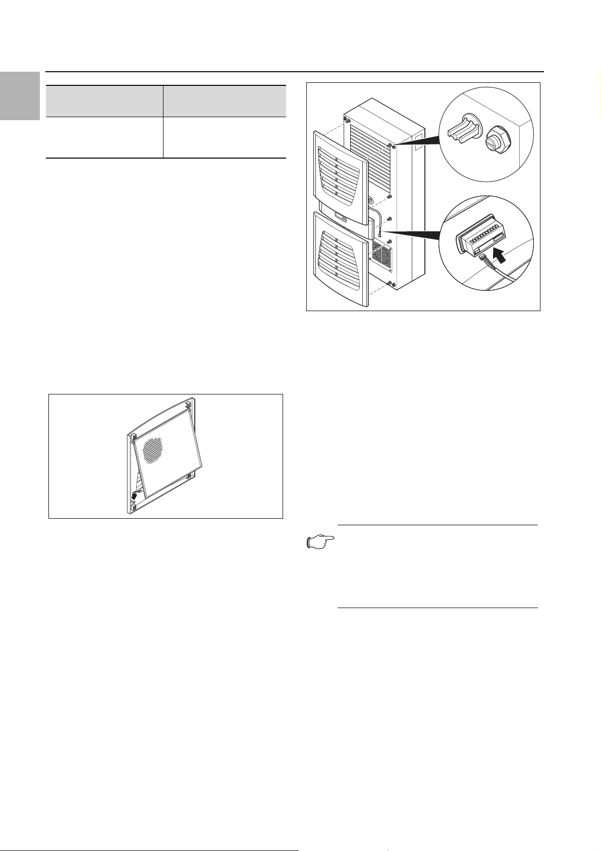
5 Start-up
EN
AC
cos φ = 1
I max. = 2 A
U max. = 250 V
Tab. 2: Relay contact data
DC
Res. Load
I min. = 100 mA
U max. = 30 V
I max. = 2 A
4.7 Finalising assembly
4.7.1 Installing the filter media
The entire cooling unit condenser is covered with a dirtrepelling, easy-to-clean RiNano coating. In many applications, therefore, the use of filter media is unnecessary,
particularly with dry dusts.
For dry, coarse dust and lint in the ambient air, we recommend installing an additional PU foam filter mat (available as an accessory) in the cooling unit. For air containing oil condensate, we recommend the use of metal filters (also available as an accessory). When used in
textile plants with heavy lint contamination, lint screens
should be used (available as an optional extra).
Pull the louvred air inlet grille off the enclosure.
Insert the filter mat into the louvred grille as shown in
fig. 22 and push it back onto the enclosure.
Fig. 23: Connect the display and attach the louvred grille
4.7.3 Setting the filter mat monitor with the e-Comfort controller
Function of the filter mat monitor:
Dirt on the filter mat is automatically detected by meas-
uring the temperature difference in the external circuit of
the cooling unit (see section6.1.6 "Programming overview"). As the level of filter mat soiling increases, the
temperature difference will increase. The setpoint value
of the temperature difference in the external circuit
adapts automatically to the relevant operating points in
the performance diagrams. Hence there is no need to
readjust the setpoint value for different unit operating
points.
Fig. 22: Installing the filter mat
4.7.2 Fitting the cooling unit
For partial and full internal mounting only.
Connect the connector to the rear of the display.
Place the louvred grille onto the unit at the front, and
press it down until you hear it snap into place.
5 Start-up
Note:
The oil must be collected in the compressor
in order to ensure effective lubrication and
cooling.
Do not operate the cooling unit for at least
30 minutes after assembling the equipment.
Once all the assembly and installation work is com-
plete, switch on the power supply to the cooling unit.
The cooling unit starts running. The software version of
the controller first appears for approx. 2 seconds, then
"ECO" to show Eco mode is enabled. The internal enclosure temperature will then appear in the 7-segment display.
28 Rittal enclosure cooling unit

6 Operation
12
4
3
ON
Status
internal fan
Internal
temperature
Time
Setpoint
-5°C
Setpoint
-10°C
OFF
10 min.
30 sec.
10 min.
You can now make your individual settings on the unit,
e.g. set the temperature or (with e-Comfort controller
only) assign the network identifier, etc. (refer to section6
"Operation").
– Visualisation of the current internal enclosure temper-
ature and all error messages in the 7-segment display
– Using an interface card (Model No. 3124.200), the unit
may be incorporated into higher-level remote monitoring systems.
Warning!
If the device is dropped, it must no
longer be put into operation.
The cooling unit operates automatically, i.e. after switching on the power supply, the evaporator fan (see fig. 3)
will run and circulate the internal enclosure air. The compressor and condenser fan are regulated by the e-Com-
6 Operation
You can operate the cooling unit using the controller on
the front of the device (fig. 2, item 11). The device is fitted
with an e-Comfort controller.
fort controller. The e-Comfort controller has a 7-segment display (fig. 24, item 4). After switching on the power supply, the current software version initially appears
on this display for approx. 2 seconds together with the
symbol to show Eco mode is enabled, followed by a pre-
6.1 Control using the e-Comfort controller
For unit types 33xx.5xx.
set option (e.g. t10) or the temperature.
In regular operation, the display shows both the temperature (in degrees Celsius or Fahrenheit – users may
switch between the two) and any error messages.
The current internal enclosure temperature is usually displayed permanently. In the event of an error message,
this alternates with the temperature display.
The unit is programmed using buttons 1 – 3 (fig. 24). The
relevant parameters also appear in the display.
6.1.2 Eco mode
All Rittal TopTherm cooling units with e-Comfort controller from firmware 3.2 have the energy-saving eco mode,
which is enabled in the delivered state.
Fig. 24: e-Comfort controller
Key
1 Programming button, also display of the set temperature
unit (degrees Celsius)
2 Set button
3 Programming button, also display of the set temperature
unit (degrees Fahrenheit)
47-segment display
The eco mode is used to save energy in the heat exchanger if there is no thermal load, or there is a low thermal load in the enclosure (e. g. standby operation, no
production or weekend). During this process the evaporator fan in the internal circuit is switched off as appropriate if the actual internal enclosure temperature drops
to 10 K below the specified setpoint temperature. To ensure the internal temperature is reliably measured during
this process, the fan starts cyclically for 30 sec. every 10
6.1.1 Properties
– Rated operating voltage:
–200 V or
–230 V or
– 400/460 V, 3-phase, supports multiple voltages
without rewiring
– Integral start-up delay and door limit switch function
minutes (see fig. 25). If the internal temperature drops to
a range 5 K below the setpoint set again, the fan switches back to continuous operation.
If required, eco mode can be disabled on the control display. For this purpose switch the parameter from 1 to 0
in the programming level (see tab.3). The fan then runs
continuously.
– Protective function to prevent icing
– Monitoring of all motors (compressor, condenser fan,
evaporator fan)
– Phase monitoring for three-phase units
– Master-slave function with a maximum of ten units.
One device functions as a master unit. Once the set
temperature is reached by one of the connected slave
devices or in the event of the door limit switch function,
the affected slave unit will report to the master unit that
switches all the other cooling units on or off as re-
quired.
– Switching hysteresis: adjustable from 2 – 10 K, preset
to 5 K
Rittal enclosure cooling unit 29
Fig. 25: Eco mode
6.1.3 Launching test mode
The e-Comfort controller is equipped with a test function
whereby the cooling unit commences cooling operation
EN

6 Operation
EN
independently of the set temperature or door limit switch
function.
Simultaneously press buttons 1 and 2 (fig. 24) for at
least 5 sec.
The cooling unit will commence operation. Test mode is
completed after approximately 5 minutes. The unit
switches off and changes to normal operation.
6.1.4 General information about programming
Using buttons 1, 2 and 3 (fig. 24) you can change
24 parameters within the preset ranges (min. value,
max. value).
Tables 3 and 4 show the parameters which can be altered. fig. 26 on page 32 shows which buttons must be
pressed.
Note on switching hysteresis:
With a low hysteresis and short switching
cycles, there is a risk that cooling may not
be adequate or that only partial sections of
the enclosure are cooled. If the cooling unit
and compressor run times are too long
< 1 minute, the switching hysteresis to protect the cooling unit is automatically increased (see message "LH" in section
6.1.9 "Evaluating system messages").
"Cod" will appear in the display. In order to be able to
change a value, you must enter the authorisation code
"22".
Keep the programming button (°C) held down until
"22" appears.
Press button 2 ("Set") to confirm the code.
You can now alter the parameter within the preset limits.
Press one of the programming buttons (°C) or
(°F) until the required value appears.
Press button 2 ("Set") to confirm the change.
You can now alter other parameters in the same way.
There is no need to re-enter the authorisation code "22".
To exit programming mode, press button 2 ("Set")
again for approximately 5 seconds.
"Acc" will appear in the display to indicate that the
changes have been saved. The display then switches
back to regular operation (internal enclosure temperature).
You can also program the e-Comfort controller using a
diagnosis software package (Model No. 3159.100),
which is supplied with a connection cable to the PC. The
cable connector on the rear of the e-Comfort controller
display serves as an interface.
Note on temperature settings:
With the e-Comfort controller, the temperature is preset at the factory to +35°C.
In order to save energy, and due to the risk
of increased condensation, do not set the
temperature lower than that actually necessary.
Note on useful cooling power:
Interactive performance diagrams for calculating the useful cooling power may be
found at www.rittal.com.
In principle, the programming is identical for all editable
parameters.
To enter programming mode:
Press button 2 ("Set") for approx. 5 seconds.
The controller is now in programming mode. While in
programming mode, if you do not press any buttons for
approx. 30 seconds, the display will first flash, then the
controller will switch back to normal display mode. "Esc"
in the display indicates that any changes made have not
been saved.
Press the programming buttons (°C) or (°F) to
switch between the editable parameters (see tables 3
and 4).
Press button 2 ("Set") to select the displayed parame-
ter for editing.
The current value of this parameter is displayed.
Press one of the programming buttons (°C) or
(°F).
30 Rittal enclosure cooling unit

6.1.5 Editable parameters
See also fig. 26 on page 26.
6 Operation
EN
Progr.
level
1 St Internal enclosure
2 Fi Filter mat monitor-
3 Ad Master-slave iden-
4 CF Switch between
5 H1 Setting for switch-
6 H2 Differential for error
Display
screen
Parameter Min.
temperature setpoint T
i
ing
tifier
°C/°F
ing difference (hysteresis)
message A2
Max.
value
20°C 55°C 35°C The internal enclosure temperature setting is
68°F 131°F 95°F
10°C 60°C 99
18°F 108°F 178
0 19 0 See section 6.1.8 "Setting the master/slave
0 1 0 The temperature display can be switched be-
2 K 10 K 5 K The cooling unit is preset in the factory to a
4°F 18°F 9°F
3 K 15 K 5 K If the internal enclosure temperature exceeds
5°F 27°F 9°F
value
Factory
setting
(= off)
(= off)
Description
preset at the factory to 35°C (95°F) and may be
altered within a range of 20 – 55°C (68 – 131°F).
To enable filter mat monitoring, the display
should be set to a minimum of 10 K (18°F)
above the temperature difference shown in programming mode "Fi"; filter mat monitoring is disabled at the factory (99 = off).
identifier".
tween °C (0) and °F (1). The LED displays the
current unit of temperature.
switching hysteresis of 5 K (9°F). This parameter
should only be changed in consultation with us.
Please contact us for advice.
the set value by more than 5 K (9°F), then error
message A2 (internal enclosure temperature too
high) appears on the display terminal. If necessary, the differential may be altered here within
the range of 3 – 15 K (5 – 27°F).
26 ECO Eco-mode opera-
tion
27 PSO Changing the au-
thorisation code
Tab. 3: Editable parameters
0 1 1 Eco mode OFF: 0 / Eco mode ON: 1
0 15 0 This parameter allows you to change the "22"
authorisation code (factory setting).
The new code results from the sum of 22 +
PSO.
Rittal enclosure cooling unit 31

EN
= 5 sec.
= 5 sec.
6 Operation
6.1.6 Programming overview
Fig. 26: Programming overview
32 Rittal enclosure cooling unit

6 Operation
6.1.7 Defining system messages for evaluation
System messages are shown on the display screen of
the e-Comfort controller via the displays A1 to A20 and
E0.
Progr.
level
7 A1 0 2 0 Enclosure door open
8 A2 0 2 0 Internal temperature of enclosure too high
9 A3 0 2 0 Filter monitoring
10 A4 0 2 0 Ambient temperature too high/low
11A5 020 Icing hazard
12A6 021 PSA
13 A7 0 2 2 Evaporator coil
14A8 021 Condensate warning
15 A9 0 2 1 Condenser fan blocked or defective
16 A10 0 2 1 Evaporator fan blocked or defective
17A11022 Compressor
Display
screen
Min.
value
Max.
value
Factory
setting
Type or location of fault
A more detailed explanation of the system messages
may be found in section 6.1.9 "Evaluating system messages".
See also fig. 26 on page 32.
H
pressure switch
EN
18A12021 Condenser
19 A13 0 2 1 Ambient temperature sensor
20 A14 0 2 1 Icing temperature sensor
21A15021 Condensate warning temperature sensor
22 A16 0 2 1 Internal temperature sensor
23A17021 Phase monitoring
24A18020 EPROM
25 A19 0 2 0 LAN/Master-Slave
Tab. 4: System messages that can be evaluated via relays
The system messages A1 – A19 may also be evaluated
via two floating system message relays. In this way, one
of the two system message relays may be allocated to
each system message.
System message relays with normally open contact, see
wiring diagrams in section 4.6.3 "Installing the power
supply":
– Terminal 3: NO (normally open, relay 2)
– Terminal 4: C (connection of the supply voltage to the
system message relay)
The RiDiag II software (available as an accessory, Model
No. 3159.100) allows you to invert the system message
relay circuit.
In the normal operating state the two relays will then
drop out. If a system message occurs, the relevant relay
will energise and the contact will close.
Note:
This setting can only be made using the
RiDiag II software.
– Terminal 5: NO (normally open, relay 1)
Program system messages with the value
The definition NO refers to the de-energised state. As
soon as power is applied to the cooling unit, both system message relays (relay 1 and 2) energise.
This is the normal operating state of the cooling unit. As
0: System message is not sent to the system mes-
sage relay, but merely appears in the display
1: System message is evaluated by relay 1
2: System message is evaluated by relay 2
soon as a system message occurs or the power supply
is interrupted, the corresponding relay will drop out and
open the contact.
Rittal enclosure cooling unit 33

6 Operation
Master
02
Slave
11
Slave
12
EN
6.1.8 Setting the master/slave identifier
When several cooling units are connected together
(maximum ten), one of the cooling units must be defined
as the "master" and the others as "slaves". For this purpose, assign a corresponding identifier (address) to
each cooling unit which will enable the cooling unit to be
identified in the network.
If one of the slave units reaches the set temperature or if
the door limit switch function is activated, the affected
slave unit will report to the master unit, which then deactivates all the other cooling units.
Notes:
– Only one unit may be configured as mas-
ter, and its identifier must match
the number of connected slave units.
– The slave units must have different identi-
fiers.
– The identifiers must be numbered in as-
cending order without any gaps.
On the master cooling unit (00 = factory setting), set
the number of slave units present in the network:
– 01: Master with 1 slave cooling unit
– 02: Master with 2 slave cooling units
– 03: Master with 3 slave cooling units
– 04: Master with 4 slave cooling units
– 05: Master with 5 slave cooling units
– 06: Master with 6 slave cooling units
– 07: Master with 7 slave cooling units
– 08: Master with 8 slave cooling units
– 09: Master with 9 slave cooling units
On the slave cooling unit (00 = factory setting), set its
own address:
– 11: Slave cooling unit no. 1
– 12: Slave cooling unit no. 2
– 13: Slave cooling unit no. 3
– 14: Slave cooling unit no. 4
– 15: Slave cooling unit no. 5
– 16: Slave cooling unit no. 6
– 17: Slave cooling unit no. 7
– 18: Slave cooling unit no. 8
– 19: Slave cooling unit no. 9
Fig. 27: Master/slave connection (example)
For further connection examples, see section4.6.1 "Bus
connection (only when interconnecting several units with
a Comfort controller)".
For details of how to set the identifier, see section6.1.5
"Editable parameters" or section6.1.6 "Programming
overview", parameter "Ad".
6.1.9 Evaluating system messages
In the e-Comfort controller, system messages are indicated by a number in the display.
Following the appearance of messages A03, A06 and
A07 and after rectifying their cause, you will need to reset the e-Comfort controller (see section6.1.10 "Reset
the e-Comfort controller").
Display
screen
A01 Enclosure door open Door open or door limit switch incor-
A02 Internal temperature of
A03 Filter monitoring Filter mat soiled Clean or replace;
A04 Ambient temperature
A05 Icing hazard Operational display in case of icing haz-
Tab. 5: Troubleshooting with the e-Comfort controller
System message Possible cause Measures to rectify the fault
Close door, position door limit switch cor-
enclosure too high
too high/low
rectly positioned
Cooling capacity inadequate/unit undersized Error as a consequence of
messages A03 to A17.
Ambient temperature outside permissible operating range (+10°C to +60°C)
ard.
Evaporator coil fan may be mechanically blocked, defective, or cold air outlet obstructed.
rectly, check connection if necessary
Check cooling capacity
reset the e-Comfort controller
Raise or lower the ambient temperature (e.g.
heat or ventilate the room)
Set the enclosure interior temperature to a
higher value. Check the evaporator fan;
release or exchange if necessary.
34 Rittal enclosure cooling unit

6 Operation
Display
screen
A06 PSAH pressure switch Ambient temperature too high Lower the ambient temperature;
A07 Evaporator coil Lack of refrigerant; sensor in front of or
A08 Condensate warning Condensate discharge kinked or
System message Possible cause Measures to rectify the fault
reset the e-Comfort controller
Condenser soiled Clean the condenser;
reset the e-Comfort controller
Filter mat soiled Clean or replace;
reset the e-Comfort controller
Condenser fan defective Replace;
reset the e-Comfort controller
E-valve defective Repair by refrigeration engineer;
reset the e-Comfort controller
H
pressure switch defective Refrigeration engineer to exchange
PSA
reset the e-Comfort controller
Repair by refrigeration engineer;
behind condenser defective
blocked
Only for units with optional condensate
evaporation
reset the e-Comfort controller
Check condensate drainage;
correct any kinks or blockages in the hose
Check the evaporation unit, replace if necessary
EN
A09 Condenser fan Blocked or defective Clear the blockage; replace if necessary
A10 Evaporator fan Blocked or defective Clear the blockage; replace if necessary
A11 Compressor Compressor overloaded (internal wind-
ing protection)
Defective (check by measuring the
winding resistance)
A12 Condenser tempera-
ture sensor
A13 Ambient temperature
sensor
A14 Icing temperature sen-
sor
A15 Condensate warning
temperature sensor
A16 Internal temperature
sensor
A17 Phase monitoring For three-phase devices only:
A18 EPROM error New board installed incorrectly Software update needed (only following
Open or short-circuit Replace
Open or short-circuit Replace
Open or short-circuit Replace
Open or short-circuit Replace
Open or short-circuit Replace
Incorrect rotary field/phase absent
No action required;
Unit switches on again independently
Replace by a refrigeration engineer
Swap two phases
board installation with more recent software): Enter the programming level with
Code 22;
press button 1 and confirm with "Set" until
"Acc" appears. Next, disconnect the unit
from the mains and reconnect.
A19 LAN/Master-Slave Master and slave not connected Check setting and/or cable
Tab. 5: Troubleshooting with the e-Comfort controller
Rittal enclosure cooling unit 35
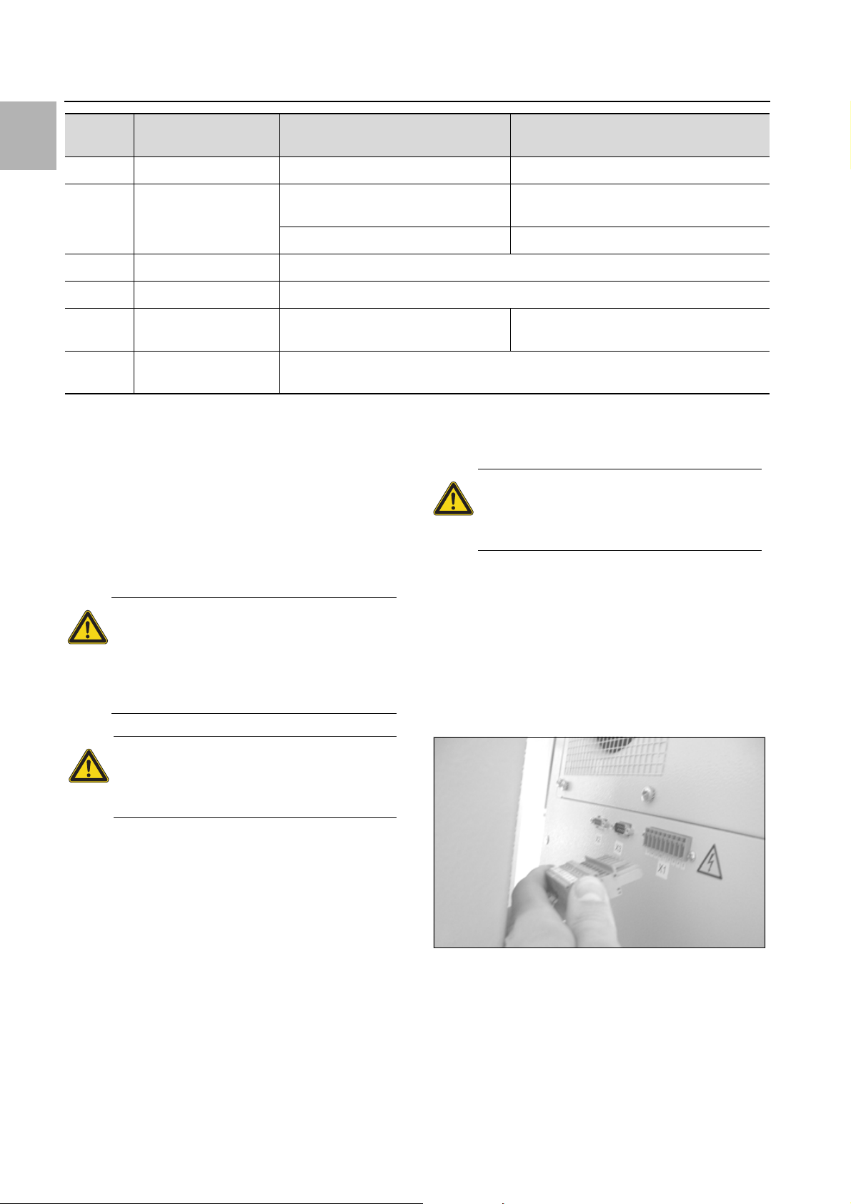
7 Inspection and maintenance
EN
Display
screen
A20 Voltage drop Error display not shown Event is stored in the log file
E0 Display message Connection problem between the dis-
OL Overload Ambient parameters or heat loss outside the applicable limits
LH Low Heat Minimal heat loss in enclosure.
b07 Leak in the cooling cir-
rSt Reset Manual device reset required,
Tab. 5: Troubleshooting with the e-Comfort controller
6.1.10 Reset the e-Comfort controller
After the occurrence of faults A03, A06 and A07, you will
need to reset the e-Comfort controller.
Press buttons 1 () and 3 () (fig. 24) simultaneously
for 5 seconds.
The system messages disappear and the temperature
display is shown.
System message Possible cause Measures to rectify the fault
Reset: Switch power supply off, then switch
play and the controller board
Cable defective; connection loose Replace the boards
Sensor B3 and B4 swapped over Swap the sensors
cuit
see section6.1.10 "Reset the e-Comfort controller".
on again after approx. 2 sec.
maintenance interval may be reduced to suit the air pollution intensity.
Caution!
Risk of fire!
Never use flammable liquids for cleaning.
7 Inspection and maintenance
Warning!
The unit is live.
Switch off the power supply before
opening, and take suitable precautions
against it being accidentally switched
back on.
Warning!
Any essential repair work on the cool-
ing circuit must only be undertaken by
Rittal.
The cooling circuit is a maintenance-free, hermetically
sealed system. The cooling unit is filled with the required
quantity of refrigerant at the factory, checked for leaks,
and subjected to a functional test run.
The installed maintenance-free fans are mounted on ball
bearings, protected against moisture and dust, and fitted with a temperature monitor. The life expectancy is at
least 30,000 operating hours (L10, 40°C). The cooling
unit is thus largely maintenance-free. All that may be required from time to time is to clean the components of
the external air circuit using a vacuum cleaner or compressed air if they become visibly dirty. Any stubborn,
oily stains may be removed using a non-flammable detergent, such as degreaser.
Maintenance interval: 2,000 operating hours. Depending
on the level of contamination in the ambient air, the
Sequence of maintenance measures:
– Check the level of dirt.
– Filter soiling? Replace the filter if necessary.
– Cooling membranes soiled? Clean if necessary.
– Activate test mode; cooling function OK?
– Check noise generation of compressor and fans.
7.1 Compressed air cleaning 3304.xxx,
3305.xxx
Fig. 28: Disconnect the mains plug
36 Rittal enclosure cooling unit

7 Inspection and maintenance
EN
Fig. 29: Remove the top louvred grille
Fig. 31: Remove the infill panel
Fig. 30: Remove the bottom louvred grille
Fig. 32: Disconnect the connector from the display (1)
Rittal enclosure cooling unit 37

EN
7 Inspection and maintenance
Fig. 33: Disconnect the connector from the display (2)
Fig. 36: Remove the fan
Fig. 37: Disconnect the fan connectors
Fig. 34: Cooling unit without grille
Fig. 35: Remove the external circuit fan (undo four screws)
38 Rittal enclosure cooling unit
Fig. 38: Remove the cover (undo the four nuts)
Fig. 39: Slide the display cable back

Fig. 40: Push the display cable through the cable gland
7 Inspection and maintenance
EN
Fig. 41: Remove the cover (1)
Fig. 42: Remove the cover (2)
Fig. 43: Release the earthing cable between the cover and the
chassis (1)
Fig. 44: Release the earthing cable between the cover and the
chassis (2)
Rittal enclosure cooling unit 39

EN
8 Storage and disposal
8 Storage and disposal
Note:
The cooling unit must not be subjected to
temperatures above +70°C during storage.
Store the cooling unit in the appropriate position for
transport.
The closed cooling cycle contains refrigerant and oil,
which must be properly disposed of for the protection of
the environment. Facilities for disposal are available at
the Rittal plant.
Please contact us for advice.
9 Technical details
9.1 Technical specifications
Fig. 45: Clean the heat exchanger coil and compressor cham-
ber using compressed air (1)
Fig. 47: Rating plate (technical data)
– Observe the mains connection data (voltage and fre-
quency) as per the rating plate.
– Observe the pre-fuse as per the specifications on the
rating plate.
Fig. 46: Clean the heat exchanger coil and compressor cham-
ber using compressed air (2)
40 Rittal enclosure cooling unit

9 Technical details
Unit Model No.
e-Comfort controller, RAL 7035 – 3303.470 3304.450 3304.470
Rated voltage V
Rated current A
Start-up current A
Pre-fuse T A
Circuit-breaker A
Transformer circuit-breaker A
Miniature circuit-breaker or
gG slow fuse (T)
Total cooling output P
to L 35 L 35
DIN EN 14511 L 35 L 50
Sensible cooling output P
to DIN EN 14511 L 35 L 35 kW
Rated output P
to L 35 L 35
DIN EN 14511 L 35 L 50
Energy efficiency
ratio (EER) 50Hz L 35 L 35
Refrigerant – Type
GWP – 4
CO2e t 0.0008 0.0014 0.0014
c
s
el
– Filling
Hz
kW
kW
kW
kW
–
–
g
200, 1~,
50/60
2.9/3.3
5.9/7.3
10
–
–
◾
0.45/0.50
0.35/0.35
0.33/0.38
0.34/0.38
0.39/0.43
1.34
R1234yf
205
230, 1~,
50/60
3.9/4.3 4.5/5.0
12.0/14.0 13.8/16.1
10 –
––
–6.3…10
◾ –
1.10/1.25
0.91/0.90
1.00/1.12 1.00/1.12
0.60/0.64
0.69/0.78
1.83 1.83
R1234yf
358
200, 1~,
50/60
1.10/1.25
0.91/0.90
0.60/0.64
0.69/0.78
R1234yf
358
EN
Permissible pressure MPa HP 2.1 LP 1.6 HP 2.8 LP 1.6 HP 2.8 LP 1.6
Operating temperature range °C +10…+50 +10…+55 +10…+55
Setting range °C +20…+55
Noise level dB (A) ≤ 61 ≤ 64
Protection category to IEC 60 529
– Internal circuit
– External circuit
UL-Type rating – 12
Dimensions (W x H x D) mm 280 x 550 x 210 400 x 950 x 260
Weight kg 17 39 44
Minimum dimensions of installation
room
–
–
m³ 4
IP 54
IP 34
Rittal enclosure cooling unit 41

9 Technical details
EN
Unit Model No.
e-Comfort controller, RAL 7035 – 3305.450 3305.470
Rated voltage V, Hz 230, 1~,
Rated current A 5.5/5.8 6.5/6.8
Start-up current A 12.0/14.0 25.0/27.0
Pre-fuse T A 16.0 –
Circuit-breaker A – –
Transformer circuit-breaker A – 6.3…10.0
Miniature circuit-breaker or
gG slow fuse (T)
Total cooling output P
to L 35 L 35
DIN EN 14511 L 35 L 50
Sensible cooling output P
to DIN EN 14511 L 35 L 35 kW 1.28/1.42 1.28/1.42
Rated output P
to L 35 L 35
DIN EN 14511 L 35 L 50
Energy efficiency
ratio (EER) 50Hz L 35 L 35 1.87 1.87
Refrigerant – Type
GWP – 4
c
s
el
– Filling
– ◾ –
kW
kW
kW
kW
–
g
50/60
1.60/1.76
1.20/1.30
0.85/0.96
0.97/1.09
R1234yf
650
200, 1~,
50/60
1.60/1.76
1.20/1.30
0.85/0.96
0.97/1.09
R1234yf
650
CO2e t 0.0026 0.0026
Permissible pressure MPa HP 2.8 LP 1.6
Operating temperature range °C +10…+55
Setting range °C +20…+55
Noise level dB (A) ≤ 64
Protection category to IEC 60 529
– Internal circuit
– External circuit
UL-Type rating – 12
Dimensions (W x H x D) mm 400 x 950 x 260
Weight kg 41 46
Minimum dimensions of installation
room
–
–
m³ 4
IP 54
IP 34
42 Rittal enclosure cooling unit

9 Technical details
9.2 Performance diagrams
Fig. 48: 3303.470, 50 Hz Fig. 49: 3303.470, 60 Hz
EN
Fig. 50: 3304.450 and 3304.470, 50 Hz Fig. 51: 3304.450 and 3304.470, 60 Hz
Fig. 52: 3305.450 and 3305.470, 50 Hz Fig. 53: 3305.450 and 3305.470, 60 Hz
Key
PcTotal cooling output
Ambient temperature
T
u
TiEnclosure internal temperature
Rittal enclosure cooling unit 43

EN
40
71
5
100
90
10
1
15
71
45
55
30
20
75
71
71
25
3303.xxx
20
71
100
90
25
45
50
10
40
71
45
55
5
15
30
75
71
71
1
80
101
3304.xxx
3305.xxx
102
10 List of spare parts
10 List of spare parts
Fig. 54: Spare parts for 3303.xxx
Fig. 55: Spare parts for 3304.xxx, 3305.xxx
44 Rittal enclosure cooling unit
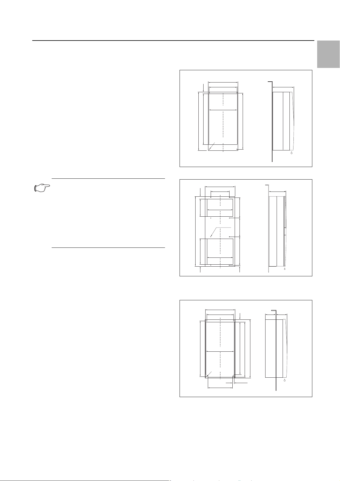
11 Appendix: Cut-out and hole sizes
262
266
280
480
15.5
550
532
Ø 8 (4x)
210
280
(230)
254
524
Ø 8 (4x)
18 x 45
266
20
497
523
550
106
100
Key
1 Compressor
5Condenser fan
10 Evaporator fan
15 Dispatch bag
20 Expansion valve
25 Filter dryer
H
30 PSA
pressure switch
40 Controller board
45 Louvred grille 1
46 Louvred grille 2
50 Infill panel
55 Display
71 Temperature sensor
75 Enclosure tray
80 Transformer
90 Evaporator coil
100 Condenser
101 Condensate evaporator
102 Miniature fuse, condensate evaporator
(T4A; 6.3 x 32 mm)
Note:
As well as the spare part number, when or-
dering spare parts the following information
must be provided:
–Unit model
– Fabrication number
– Date of manufacture
This information may be found on the rating
plate.
11 Appendix: Cut-out and hole sizes
11.1 Dimensions for external mounting
Fig. 56: 3303.xxx external mounting
950
32.5
255
400
250
350
Ø 9.5 (8x)
280
255
260
EN
350
25
350
385
15
Fig. 57: 3304.xxx, 3305.xxx external mounting
11.2 Dimensions for partial internal mounting
Fig. 58: 3303.xxx partial internal mounting
Rittal enclosure cooling unit 45

11 Appendix: Cut-out and hole sizes
42
168
(230)
18 x 45˚
Ø 19 (2x)
Ø 8 (4x)
280
200
254
25
266
492
518
550
524
200
R95
400
210
50
950
920
920
25 x 45º
2
370
25
6 (4x)
380
20 x 45º
2
Ø9,5 (4x)
EN
400
370
330
155
105
25 x 45º
950
920
380
920
20 x 45º
Ø9,5 (4x)
Fig. 59: 3304.xxx, 3305.xxx partial internal mounting
11.3 Dimensions for full internal mounting
Fig. 61: 3304.xxx, 3305.xxx full internal mounting
Fig. 60: 3303.xxx full internal mounting
46 Rittal enclosure cooling unit

12 Safety data sheet
SAFETY DATA SHEET according to Regulation (EC) No 1907/2006 -
Annex II
Opteon™ YF Refrigerant
Version 10.1 (replaces: Version 10.0)
Revision Date 04.05.2016
Ref. 130000043292
1/27
This Safety Data Sheet adheres to the standards and regulatory requirements of Great Britain and may not meet the
regulatory requirements in other countries.
SECTION 1: Identification of the substance/mixture and of the company/undertaking
1.1. Product identifier
Product name
:
Opteon™ YF Refrigerant
Registration number
:
01-0000019665-61-0001
Synonyms
:
2,3,3,3-Tetrafluoropropene
Identification number
:
CAS-No. 754-12-1 EC-No. 468-710-7
1.2. Relevant identified uses of the substance or mixture and uses advised against
Use of the Substance/Mixture
:
For professional and industrial installation and use only., Heat transfer fluids Refrigerants, coolants, Formulation of preparations
Uses advised against
:
Open evaporation applications., Direct use of the substance by consumers.,
Consumer filling of mobile air conditioning units.
1.3. Details of the supplier of the safety data sheet
Company
:
Chemours Netherlands B.V.
Baanhoekweg 22
NL-3313 LA Dordrecht
Netherlands
Telephone
:
+31-(0)-78-630-1011
Telefax
:
+31-78-6163737
E-mail address
:
sds-support@chemours.com
1.4. Emergency telephone number
Emergency telephone number
:
+(44)-870-8200418 (CHEMTREC - Recommended)
SECTION 2: Hazards identification
2.1. Classification of the substance or mixture
Flammable gases, Category 1
H220: Extremely flammable gas.
Gases under pressure,
Liquefied gas
H280: Contains gas under pressure; may explode if heated.
2.2. Label elements
12 Safety data sheet
EN
Rittal enclosure cooling unit 47

12 Safety data sheet
SAFETY DATA SHEET according to Regulation (EC) No 1907/2006 -
Annex II
Opteon™ YF Refrigerant
Version 10.1 (replaces: Version 10.0)
Revision Date 04.05.2016
Ref. 130000043292
2/27
Danger
H220
Extremely flammable gas.
H280
Contains gas under pressure; may explode if heated.
P210
Keep away from heat, hot surfaces, sparks, open flames and other ignition
sources. No smoking.
P377
Leaking gas fire: Do not extinguish, unless leak can be stopped safely.
P381
Eliminate all ignition sources if safe to do so.
P410 + P403
Protect from sunlight. Store in a well-ventilated place.
2.3. Other hazards
This substance is not considered to be persistent, bioaccumulating and toxic (PBT).
This substance is not considered to be very persistent and very bioaccumulating (vPvB).
Misuse or intentional inhalation abuse may cause death without warning symptom s, due to cardiac effects.
Vapours are heavier than air and can cause suffocation by reducing oxygen available for breathing.
Rapid evaporation of the liquid may cause frostbite.
SECTION 3: Composition/information on ingredients
3.1. Substances
Registration number
Classification according to
Regulation (EU) 1272/2008 (CLP)
Concentration
(% w/w)
2,3,3,3-Tetrafluoropropene (CAS-No.754-12-1) (EC-No.468-710-7)
01-0000019665-61-0001
Flam. Gas 1; H220
Press. Gas Liquefied gas; H280
>= 99.5 %
3.2. Mixtures
Not applicable
The above products are compliant to REACH registration obligations; Registration number(s) may not be
provided because substance(s) are exempted, not yet registered under REACH or are registered under another
regulatory process (biocide uses, plant protection products), etc.
EN
48 Rittal enclosure cooling unit
SAFETY DATA SHEET according to Regulation (EC) No 1907/2006 -
Annex II
Opteon™ YF Refrigerant
Version 10.1 (replaces: Version 10.0)
Revision Date 04.05.2016
Ref. 130000043292
3/27
For the full text of the H-Statements mentioned in this Section, see Section 16.
SECTION 4: First aid measures
4.1. Description of first aid measures
General advice
:
If unconscious place in recovery position and seek medical advice. Never give
anything by mouth to an unconscious person.
If breathing is irregular or
stopped, administer artificial respiration.
: First aider needs to protect himself.
: If symptoms persist, call a physician.
Inhalation
:
Remove from exposure, lie down. Move to fresh air. Keep patient warm and at
rest.
Artificial respiration and/or oxygen may be necessary. Consult a
physician.
Skin contact
:
Take off all contaminated clothing immediately. Flush area with lukewarm
water. Do not use hot water. If frostbite has occurred, call a physician.
Eye contact
:
Hold eyelids apart and flush eyes with plenty of water for at least 15 minutes.
Get medical attention.
Ingestion
:
Is not considered a potential route of exposure.
4.2. Most important symptoms and effects, both acute and delayed
Symptoms
:
Misuse or intentional inhalation abuse may cause death without warning
symptoms, due to cardiac effects.
, Other symptoms potentially related to
misuse or inhalation abuse are:
, Anaesthetic effects, Light-headedness,
Dizziness, Confusion, Incoordination, Drowsiness, Unconsciousness
: Contact with liquid or refrigerated gas can cause cold burns and frostbite.
4.3. Indication of any immediate medical attention and special treatment needed
Treatment
:
Remove from exposure, lie down. Move to fresh air. Keep patient warm and at
rest.
Artificial respiration and/or oxygen may be necessary. Consult a
physician.
SECTION 5: Firefighting measures
5.1. Extinguishing media
Suitable extinguishing media
:
Use extinguishing measures that are appropriate to local circumstances and the
surrounding environment.
: Use water spray, alcohol-resistant foam, dry chemical or carbon dioxide.
12 Safety data sheet
EN
Rittal enclosure cooling unit 49

12 Safety data sheet
SAFETY DATA SHEET according to Regulation (EC) No 1907/2006 -
Annex II
Opteon™ YF Refrigerant
Version 10.1 (replaces: Version 10.0)
Revision Date 04.05.2016
Ref. 130000043292
4/27
5.2. Special hazards arising from the substance or mixture
Specific hazards during
firefighting
:
Vapours may form flammable mixture with air. Pressure build-up. Fire or intense
heat may cause violent rupture of packages.
: Hazardous combustion products:
: Hydrogen fluoride
: Fluorinated compounds
: Carbon oxides
: Exposure to decomposition products may be a hazard to health.
5.3. Advice for firefighters
Special protective equipment
for firefighters
:
In the event of fire, wear self-contained breathing apparatus. Use personal
protective equipment. Wear neoprene gloves during cleaning up work after a
fire.
Further information
:
Cool containers/tanks with water spray. Allow to burn until flow can be stopped.
SECTION 6: Accidental release measures
6.1. Personal precautions, protective equipment and emergency procedures
Personal precautions
:
Evacuate personnel to safe areas, if necessary. Ventilate area, especially low or
enclosed places where heavy vapours might collect.
Refer to protective
measures listed in sections 7 and 8.
6.2. Environmental precautions
Environmental precautions
:
Should not be released into the environment. In accordance with local and
national regulations.
6.3. Methods and materials for containment and cleaning up
Methods for cleaning up
:
Evaporates.
6.4. Reference to other sections
For disposal instructions see section 13.
SECTION 7: Handling and storage
7.1. Precautions for safe handling
Advice on safe handling
:
Avoid breathing vapours or mist. Avoid contact with skin, eyes and clothing.
Provide sufficient air exchange and/or exhaust in work rooms.
For personal
protection see section 8.
For further information see Annex - Exposure scenario.
EN
50 Rittal enclosure cooling unit

SAFETY DATA SHEET according to Regulation (EC) No 1907/2006 -
Annex II
Opteon™ YF Refrigerant
Version 10.1 (replaces: Version 10.0)
Revision Date 04.05.2016
Ref. 130000043292
5/27
Advice on protection
against fire and explosion
:
Vapours are heavier than air and may spread along floors. Vapours may form
flammable mixture with air.
The product should only be used in areas from
which all naked lights and effective sources of ignition have been excluded.
Electrical equipment should be
protected to the appropriate standard. Take
measures to prevent the build up of electrostatic charge. Keep away from heat
and effective sources of ignition.
When using do not smoke.
7.2. Conditions for safe storage, including any incompatibilities
Requirements for storage
areas and containers
:
Gas cylinder : Do not drag, slide or roll cylinders. Never attempt to lift cylinder
by its cap.
Use a check valve or trap in the discharge line to prevent hazardous
back flow into the cylinder.
Keep at temperature not exceeding 52°C. Keep
containers tightly closed in a dry, cool and well
-ventilated place.
Store in original
container.
Protect cylinders from damage. Keep away from direct sunlight.
Protect from contamination.
Advice on common storage
:
No materials to be especially mentioned.
7.3. Specific end use(s)
For further information see Annex - Exposure scenario.
SECTION 8: Exposure controls/personal protection
8.1. Control parameters
If sub-section is empty then no values are applicable.
Derived No Effect Level (DNEL)
● 2,3,3,3-
Tetrafluoropropene
:
Type of Application (Use): Workers
Exposure routes
: Inhalation
Health Effect
: Long-term - systemic effects
Value
: 950 mg/m3
Predicted No Effect Concentration (PNEC)
● 2,3,3,3Tetrafluoropropene
:
Value: 0.1 mg/l
Compartment
: Fresh water
: Value: 1 mg/l
Compartment
: Water
Remarks
: Intermittent use/release
:
Value: 1.77 mg/kg dry weight (d.w.)
Compartment
: Fresh water sediment
: Value: 1.54 mg/kg dry weight (d.w.)
Compartment: Soil
12 Safety data sheet
EN
Rittal enclosure cooling unit 51

12 Safety data sheet
SAFETY DATA SHEET according to Regulation (EC) No 1907/2006 -
Annex II
Opteon™ YF Refrigerant
Version 10.1 (replaces: Version 10.0)
Revision Date 04.05.2016
Ref. 130000043292
6/27
: Value: 0.01 mg/l
Compartment
: Marine water
: Value: 0.178 mg/kg dry weight (d.w.)
Compartment
: Marine sediment
8.2. Exposure controls
Engineering measures
:
Ensure adequate ventilation, especially in confined areas.
Eye protection
:
Wear safety glasses or coverall chemical splash goggles. Eye protection
complying with EN 166.
or ANSI Z87.1
Additionally wear a face shield where the
possibility exists for face contact due to splashing, spraying or airborne contact
with this material.
Hand protection
:
The choice of an appropriate glove does not only depend on its material but also
on other quality features and is different from one producer to the other.
Please
observe the instructions regarding permeability and breakthrough time which
are provided by t
he supplier of the gloves. Also take into consideration the
specific local conditions under which the product is used, such as the danger of
cuts, abrasion, and the contact time.
: Material: Leather gloves
The suitability for a specific workplace should be discussed with the producers
of the protective gloves.
: Material: Low temperature resistant gloves
:
Protective gloves complying with EN 374. or US OSHA guidelines
Skin and body protection
:
Wear suitable protective equipment. Wear as appropriate: Flame retardant
antistatic protective clothing.
The type of protective equipment must be selected according to the
concentration and amount of the substance at the specific workplace.
Protective measures
:
When using do not smoke.
Self-contained breathing apparatus (SCBA) is required if a large release occurs.
The type of protective equipment must be selected according to the
concentration and amount of the substance at the specific workplace.
Hygiene measures
:
Handle in accordance with good industrial hygiene and safety practice.
Respiratory protection
:
For rescue and maintenance work in storage tanks use self-contained breathing
apparatus. Vapours are heavier than air and can cause suffocation by reducing
EN
52 Rittal enclosure cooling unit

SAFETY DATA SHEET according to Regulation (EC) No 1907/2006 -
Annex II
Opteon™ YF Refrigerant
Version 10.1 (replaces: Version 10.0)
Revision Date 04.05.2016
Ref. 130000043292
7/27
oxygen available for breathing. Respiratory protection complying with EN 137.
SECTION 9: Physical and chemical properties
9.1. Information on basic physical and chemical properties
Form
:
Liquefied gas
Colour
:
colourless
Odour
:
slight, ether-like
Boiling point
:
-29 °C at 1,013 hPa
Auto-ignition temperature
:
405 °C at 1,013 hPa, Method: Directive 67/548/EEC, Annex V, A.15., static test
Explosive properties
:
Not explosive
Lower explosion limit/ lower
flammability limit
:
Type: lower flammability limit, 6.2 vol%, Method: ASTM E681
Upper explosion limit/ upper
flammability limit
:
Type: upper flammability limit, 12.3 vol%, Method: ASTM E681
Vapour pressure
:
5,800 hPa at 20 °C
Density
:
0.0048 g/cm3 at 20 °C (1,013 hPa) , Vapour density
Water solubility
:
0.1982 g/l at 24 °C
Partition coefficient: noctanol/water
:
log Pow: 2 at 25 °C, Method: High-performance liquid chromatography
Minimum ignition energy
:
5 - 10 J at 1,013 hPa and at 20 °C
Method
: modified ASTM E582
9.2. Other information
Phys.-chem./other information
:
Fundamental burning velocity: 1.5 cm/s (Method: AIST Japan).
SECTION 10: Stability and reactivity
10.1. Reactivity
:
Hazardous polymerisation does not occur.
10.2. Chemical stability
:
The product is chemically stable.
12 Safety data sheet
EN
Rittal enclosure cooling unit 53

12 Safety data sheet
SAFETY DATA SHEET according to Regulation (EC) No 1907/2006 -
Annex II
Opteon™ YF Refrigerant
Version 10.1 (replaces: Version 10.0)
Revision Date 04.05.2016
Ref. 130000043292
8/27
10.3. Possibility of
hazardous reactions
: Vapours may form flammable mixture with air.
10.4. Conditions to avoid
:
Keep away from: Heat, flames and sparks. Do not spray on a naked flame or
any incandescent material.
Gas cylinder :
Keep at temperature not exceeding
52°C. Pressurized container: Do not pierce or burn, even after use.
10.5. Incompatible materials
:
Strong bases
Alkaline earth metals
finely divided metal powders
such as
Aluminium
Magnesium
Zinc
or
strong oxidizers
10.6. Hazardous
decomposition products
:
Hazardous thermal decomposition products may include:
Hydrogen fluoride
Fluorinated compounds
Carbon oxides
SECTION 11: Toxicological information
11.1. Information on toxicological effects
Acute inhalation toxicity
x
2,3,3,3-Tetrafluoropropene
LC50 / 4 h Rat :> 405000 ppm
Low Observed Adverse Effect Concentration (LOAEC) / Dog :> 120000 ppm
Cardiac sensitization
No Observed Adverse Effect Concentration / Dog :120000 ppm
Cardiac sensitization
Skin irritation
x
2,3,3,3-Tetrafluoropropene
Not tested on animals
Classification: Not classified as irritant
Result: No skin irritation
Not expected to cause skin irritation based on expert review of the properties of the substance.
Eye irritation
x
2,3,3,3-Tetrafluoropropene
Not tested on animals
EN
54 Rittal enclosure cooling unit

SAFETY DATA SHEET according to Regulation (EC) No 1907/2006 -
Annex II
Opteon™ YF Refrigerant
Version 10.1 (replaces: Version 10.0)
Revision Date 04.05.2016
Ref. 130000043292
9/27
Classification: Not classified as irritant
Result: No eye irritation
Not expected to cause eye irritation based on expert review of the properties of the substance.
Sensitisation
x
2,3,3,3-Tetrafluoropropene
Not tested on animals
Classification: Does not cause skin sensitisation.
Not expected to cause sensitization based on expert review of the properties of the substance.
There are no reports of human respiratory sensitization.
Repeated dose toxicity
x
2,3,3,3-Tetrafluoropropene
Inhalation Rat
NOAEL: 233 mg/l
No toxicologically significant effects were found.
Inhalation Rabbit
NOAEL: 2.33 mg/l
No toxicological effects warranting significant target organ toxicity classification were seen below the
recommended guidance values for classification.
Inhalation Mini-pig
NOAEL: 50 mg/l
No toxicologically significant effects were found.
Mutagenicity assessment
x
2,3,3,3-Tetrafluoropropene
Animal testing did not show any mutagenic effects. Did not cause genetic damage in cultured mammalian
cells. Experiments showed mutagenic effects in cultured bacterial cells.
Carcinogenicity assessment
x
2,3,3,3-Tetrafluoropropene
Not classifiable as a human carcinogen. Sufficient data are available to conclude that the substance is not
expected to be carcinogenic.
Toxicity to reproduction assessment
x
2,3,3,3-Tetrafluoropropene
No toxicity to reproduction Animal testing showed no reproductive toxicity.
Assessment teratogenicity
x
2,3,3,3-Tetrafluoropropene
12 Safety data sheet
EN
Rittal enclosure cooling unit 55

12 Safety data sheet
SAFETY DATA SHEET according to Regulation (EC) No 1907/2006 -
Annex II
Opteon™ YF Refrigerant
Version 10.1 (replaces: Version 10.0)
Revision Date 04.05.2016
Ref. 130000043292
10/27
Animal testing showed effects on embryo-fetal development at levels equal to or above those causing
maternal toxicity.
Further information
Cardiac sensitisation threshold limit : > 559509 mg/m3
Liquefied gas
Avoid skin contact with leaking liquid (danger of frostbite).
SECTION 12: Ecological information
12.1. Toxicity
Toxicity to fish
x
2,3,3,3-Tetrafluoropropene
LC50 / 96 h / Cyprinus carpio (Carp): > 197 mg/l
Toxicity to aquatic plants
x
2,3,3,3-Tetrafluoropropene
NOEC / 72 h / Algae: > 100 mg/l
Toxicity to aquatic invertebrates
x
2,3,3,3-Tetrafluoropropene
EC50 / 48 h / Daphnia magna (Water flea): > 100 mg/l
12.2. Persistence and degradability
Biodegradability
aerobic / 28 d
Biodegradation: < 5 %
Method: OECD Test Guideline 301F
According to the results of tests of biodegradability this product is not readily biodegradable.
12.3. Bioaccumulative potential
Bioaccumulation
No bioaccumulation is to be expected (log Pow <= 4).
12.4. Mobility in soil
no data available
EN
56 Rittal enclosure cooling unit

SAFETY DATA SHEET according to Regulation (EC) No 1907/2006 -
Annex II
Opteon™ YF Refrigerant
Version 10.1 (replaces: Version 10.0)
Revision Date 04.05.2016
Ref. 130000043292
11/27
12.5. Results of PBT and vPvB assessment
PBT and vPvB assessment
This substance is not considered to be persistent, bioaccumulating and toxic (PBT).
This substance is not considered to be very persistent and very bioaccumulating (vPvB).
12.6. Other adverse effects
Ozone depletion potential
0
Global warming potential (GWP)
< 1
SECTION 13: Disposal considerations
13.1. Waste treatment methods
Product
:
Can be used after re-conditioning. If re-conditioning is not practicable, dispose
of in compliance with local regulations.
For further information see Annex - Exposure scenario.
Contaminated packaging
:
Empty pressure vessels should be returned to the supplier.
If recycling is not practicable, dispose of in compliance with local regulations.
SECTION 14: Transport information
ADR
14.1.
UN number:
3161
14.2.
UN proper shipping name:
LIQUEFIED GAS, FLAMMABLE, N.O.S. (2,3,3,3Tetrafluoropropene)
14.3.
Transport hazard class(es):
2
14.4.
Packing group:
Not applicable
14.5.
Environmental hazards:
For further information see Section 12.
14.6. Special precautions for user:
Tunnel restriction code:
(B/D)
IATA_C
14.1.
UN number:
3161
14.2.
UN proper shipping name:
Liquefied gas, flammable, n.o.s. (2,3,3,3-Tetrafluoropropene)
14.3.
Transport hazard class(es):
2.1
14.4.
Packing group:
Not applicable
14.5.
Environmental hazards :
For further information see Section 12.
14.6. Special precautions for user:
ICAO / IATA cargo aircraft only
IMDG
12 Safety data sheet
EN
Rittal enclosure cooling unit 57

12 Safety data sheet
SAFETY DATA SHEET according to Regulation (EC) No 1907/2006 -
Annex II
Opteon™ YF Refrigerant
Version 10.1 (replaces: Version 10.0)
Revision Date 04.05.2016
Ref. 130000043292
12/27
14.1.
UN number:
3161
14.2.
UN proper shipping name:
LIQUEFIED GAS, FLAMMABLE, N.O.S. (2,3,3,3Tetrafluoropropene)
14.3.
Transport hazard class(es):
2.1
14.4.
Packing group:
Not applicable
14.5.
Environmental hazards :
For further information see Section 12.
14.6. Special precautions for user:
14.7. Transport in bulk according to Annex II of MARPOL and the IBC Code
SECTION 15: Regulatory information
15.1. Safety, health and environmental regulations/legislation specific for the substance or mixture
Other regulations
:
Take note of Directive 98/24/EC on the protection of the health and safety of
workers from the risks related to chemical agents at work.
Directive 1999/92/EC of the European Parliament and of the Council of 16
December 1999 on minimum requirements for
improving the safety and health
protection of workers potentially at risk from explosive atmospheres - ATEX 137.
Communication from the Commission concerning the non-binding guide of good
practice for implementing Directive 1999/92/EC of the European Parliament and
of the Council on minimum requirements for improving the safety and health
protection of workers potentially at risk from expl
osive atmospheres -
COM/2003/0515 final.
Directive 94/9/EC of the European Parliament and the Council of 23 March 1994
on the approximation of the laws of the Member States concerning equipment
and protective systems intended for use in potentially explosive atmospheres ATEX 95.
Take note of Directive 96/82/EC on the control of major-accident hazards
involving dangerous substances.
Directive 2000/53/EC of the European Parliament and of the Council of 18
September 2000 on end-of life vehicles.
15.2. Chemical Safety Assessment
A Chemical Safety Assessment has been carried out for this substance.
SECTION 16: Other information
Full text of H-Statements referred to under section 3.
H220
Extremely flammable gas.
H280
Contains gas under pressure; may explode if heated.
Abbreviations and acronyms
ADR
European Agreement concerning the International Carriage of Dangerous Goods by
Road
no data available
Not applicable
EN
58 Rittal enclosure cooling unit

SAFETY DATA SHEET according to Regulation (EC) No 1907/2006 -
Annex II
Opteon™ YF Refrigerant
Version 10.1 (replaces: Version 10.0)
Revision Date 04.05.2016
Ref. 130000043292
13/27
ATE
Acute toxicity estimate
CAS-No.
Chemical Abstracts Service number
CLP
Classification, Labelling and Packaging
EbC50
Concentration at which 50% reduction of biomass is observed
EC50
Median effective concentration
EN
European Norm
EPA
Environmental Protection Agency
ErC50
Concentration at which a 50% inhibition of growth rate is observed
EyC50
Concentration at which 50 % inhibition of yield is observed
IATA_C
International Air Transport Association (Cargo)
IBC
International Bulk Chemical Code
ICAO
International Civil Aviation Organization
ISO
International Standard Organization
IMDG
International Maritime Dangerous Goods
LC50
Median Lethal Concentration
LD50
Median Lethal Dose
LOEC
Lowest Observed Effect Concentration
LOEL
Lowest observed effect level
MARPOL
International Convention for the Prevention of Marine Pollution from Ships
n.o.s.
Not Otherwise Specified
NOAEC
No Observed Adverse Effect Concentration
NOAEL
No observed adverse effect level
NOEC
No Observed Effect Concentration
NOEL
No Observed Effect Level
OECD
Organisation for Economic Co-operation and Development
OPPTS
Office of Prevention, Pesticides and Toxic Substances
PBT
Persistent, Bioaccumulative and Toxic
STEL
Short term exposure limit
TWA
Time Weighted Average (TWA):
vPvB
very Persistent and very Bioaccumulative
Further information
Opteon
™
and any associated logos are trademarks or copyrights of The Chemours Company FC, LLC.
Chemours
™
and the Chemours Logo are trademarks of The Chemours Company.
Before use read Chemours safety information.
For further information contact the local Chemours office or nominated distributors.
Significant change from previous version is denoted with a double bar.
The information provided in this Safety Data Sheet is correct to the best of our knowledge, information and belief at
the date of its publication. The information given is designed only as a guide for safe handling, use, processing,
storage, transportation, disposal and release and is not to be considered a warranty or quality specification. The
above information relates only to the specific material(s) designated herein and may not be valid for such material(s)
used in combination with any other materials or in any process or if the material is altered or processed, unless
specified in the text.
12 Safety data sheet
EN
Rittal enclosure cooling unit 59

12 Safety data sheet
SAFETY DATA SHEET according to Regulation (EC) No 1907/2006 -
Annex II
Opteon™ YF Refrigerant
Version 10.1 (replaces: Version 10.0)
Revision Date 04.05.2016
Ref. 130000043292
14/27
Annex - Exposure scenario
The exposure scenario provides specific information on how hazardous substances (as such or in a mixture) are to be
managed and controlled. It considers specific conditions of use, in order to ensure that a use should be safe to humans
and the environment. Identified risk management measures are to be implemented unless the downstream user is able to
ensure safe use in a diverging way.
ES1 - Industrial use, Heat transfer fluids - Refrigerants, coolants
ES2 - Professional use, Heat transfer fluids - Refrigerants, coolants
ES3 - Industrial use, Formulation of preparations
Exposure scenario 1:
1. Short title of Exposure Scenario: Industrial use, Heat transfer fluids - Refrigerants, coolants
Main User Group
:
SU 3: Industrial uses: Uses of substances as such or in preparations at
industrial sites
Sector of End Use
:
SU 10: Formulation [mixing] of preparations and/or re-packaging (excluding
alloys)
:
SU17: General manufacturing, e.g. machinery, equipment, vehicles, other
transport equipment
Product Category
:
PC16: Heat transfer fluids
Further information
:
AC1: Vehicles
:
AC2: Machinery, mechanical appliances, electrical/electronic articles
CS1 : Industrial use of substances in closed systems (ERC7)
CS2 : Transfer of substance or preparation into small containers (dedicated filling line,
including weighing) (PROC9)
CS3 : Transfer of substance or preparation (charging/discharging) from/to
vessels/large containers at dedicated facilities (PROC8b)
2. Conditions of use affecting exposure
2.1 Control of environmental exposure for: CS1 - Industrial use of substances in closed systems (ERC7)
ECETOC TRA v3.0 Environment.
Product characteristics
EN
60 Rittal enclosure cooling unit

SAFETY DATA SHEET according to Regulation (EC) No 1907/2006 -
Annex II
Opteon™ YF Refrigerant
Version 10.1 (replaces: Version 10.0)
Revision Date 04.05.2016
Ref. 130000043292
15/27
Low global warming potential. Liquefied gas
Not biodegradable
Covers the percentage of the substance in the product up to 100 % (unless stated differently).
Amount used
Annual use rate (tonnes/year)
:
9000 ton(s)/year - EU
Frequency and duration of use
Continuous use/release
:
8 hours/day, Continuous use
Continuous use/release
:
200 days/year, Intermittent release.
Other given operational conditions affecting environmental exposure
Remarks
:
Under normal conditions of use, exposure would primarily occur when workers
connect and disconnect the couplings.
Release fraction to air from
process (initial release prior to
RMM)
:
0.01
Remarks
:
Worst case assumption
Technical and organisational conditions and measures
Air : Ensure that the valves of the cylinders are tightly closed and not leaking.
Water
:
Process designed to minimize releases to wastewater.
Soil : Process designed to minimize releases to soil.
Remarks
:
Handle substance within a closed system. Transfer via enclosed lines. Clear
transfer lines prior to de-coupling.
Remarks
:
Technical measures/Precautions Flammability (gases) : Directive 1999/92/EC of
the European Parliament and of the Council of 16 December 1999 on minimum
requirements for improving the safety and health protection of workers
potentially at risk from explosive atmospheres
-
ATEX 137. Directive 94/9/EC of
the European Parliament and the Council of 23 March 1994 on the
approximation of the laws of the Member States concerning equipment and
protective systems intended for use in potentially explosive atmospheres
-
ATEX 95. Take note of Directive 98/24/EC on the protection of the health and
safety of workers from the risks related to chemical agents at work.
12 Safety data sheet
EN
Rittal enclosure cooling unit 61

SAFETY DATA SHEET according to Regulation (EC) No 1907/2006 -
Annex II
Opteon™ YF Refrigerant
Version 10.1 (replaces: Version 10.0)
Revision Date 04.05.2016
Ref. 130000043292
16/27
Remarks
:
Regular inspection and maintenance of equipment and machines.
Conditions and measures related to municipal sewage treatment plant
Type of Sewage Treatment
Plant
:
No sewage treatment plant
Conditions and measures related to external treatment of waste
Remarks
:
No waste generated as substance is a gas.
2.2 Control of worker exposure for: CS2 - Transfer of substance or preparation into small containers
(dedicated filling line, including weighing) (PROC9)
Workplace measurements
For comparison purposes only, ECETOC TRA version 3.0 was also used to estimate inhalation exposure for
workers.
Product characteristics
Concentration of the
Substance in Mixture/Article
:
Liquefied gas
: Covers the percentage of the substance in the product up to 100 % (unless
stated differently).
Remarks
:
Assumes activities are at room temperature.
Amount used - Frequency and duration of use
Amount per Shift
:
120 kg
Exposure duration
:
20 min
Frequency of use
:
Intermittent release.
Frequency of use
:
200 days/year
Frequency of use
:
Under normal operation exposure occurs only at ending of filling process
(disconnection), estimated at 0.083 min (5 sec) per disconnecting process*1
processes/fill*30 fills/hr*8 hr/shift.
Other operational conditions affecting workers exposure
Breathing volume
:
10 m3
Remarks
:
Covers daily exposures up to 8 hours (unless stated differently).
Outdoor / Indoor
:
Indoor use
Minimum room size
:
50 m3
SAFETY DATA SHEET according to Regulation (EC) No 1907/2006 -
Annex II
Opteon™ YF Refrigerant
Version 10.1 (replaces: Version 10.0)
Revision Date 04.05.2016
Ref. 130000043292
17/27
Ventilation rate per hour
:
3
Remarks
:
Under normal conditions of use, exposure would primarily occur when workers
connect and disconnect the couplings.
Technical and organisational conditions and measures
Ensure that the valves of the cylinders are tightly closed and not leaking. Handle substance within a closed system.
Transfer via enclosed lines. Clear transfer lines prior to de-coupling.
Local exhaust ventilation (Effectiveness: < 10 ppm)
Technical measures/Precautions Flammability (gases) : Directive 1999/92/EC of the European Parliament and of
the Council of 16 December 1999 on minimum requirements for improving the safety and health protection of
workers potentially at risk from explosive atm
ospheres -
ATEX 137. Directive 94/9/EC of the European Parliament
and the Council of 23 March 1994 on the approximation of the laws of the Member States concerning equipment
and protective systems intended for use in potentially explosive atmospheres
- ATE
X 95. Take note of Directive
98/24/EC on the protection of the health and safety of workers from the risks related to chemical agents at work.
ISO 13043:2011
- Road vehicles - Refrigerant systems used in mobile air conditioning systems (MAC) - Safety
requi
rements SAE J639 - Safety Standards for Motor Vehicle Refrigerant Vapor Compressions Systems SAE
J2845
- R-1234yf [HFO-1234yf] and R-
744 Technician Training for Service and Containment of Refrigerants Used
in Mobile A/C Systems
Regular inspection and maintenance of equipment and machines. Ensure operatives are trained to minimise
exposures.
Conditions and measures related to personal protection, hygiene and health evaluation
Use eye protection to EN 166, designed to protect against liquid splashes. or ANSI Z87.1
Protective gloves complying with EN 374. or US OSHA guidelines
2.3 Control of worker exposure for: CS3 - Transfer of substance or preparation (charging/discharging)
from/to vessels/large containers at dedicated facilities (PROC8b)
Workplace measurements
For comparison purposes only, ECETOC TRA version 3.0 was also used to estimate inhalation exposure for
workers.
Product characteristics
Concentration of the
Substance in Mixture/Article
:
Liquefied gas
: Covers the percentage of the substance in the product up to 100 % (unless
stated differently).
Remarks
:
Assumes activities are at room temperature.
Amount used - Frequency and duration of use
12 Safety data sheet
EN
Rittal enclosure cooling unit 63

12 Safety data sheet
SAFETY DATA SHEET according to Regulation (EC) No 1907/2006 -
Annex II
Opteon™ YF Refrigerant
Version 10.1 (replaces: Version 10.0)
Revision Date 04.05.2016
Ref. 130000043292
18/27
Amount per Use
:
Not relevant
Frequency of use
:
200 days/year
Exposure duration
:
< 15 min
Frequency of use
:
Intermittent release.
Other operational conditions affecting workers exposure
Breathing volume
:
10 m3
Remarks
:
Covers daily exposures up to 8 hours (unless stated differently).
Outdoor / Indoor
:
Outdoor use
Remarks
:
Under normal conditions of use, exposure would primarily occur when workers
connect and disconnect the couplings.
Technical and organisational conditions and measures
Ensure that the valves of the cylinders are tightly closed and not leaking. Handle substance within a closed system.
Transfer via enclosed lines. Clear transfer lines prior to de-coupling.
Technical measures/Precautions Flammability (gases) : Directive 1999/92/EC of the European Parliament and of
the Council of 16 December 1999 on minimum requirements for improving the safety and health protection of
workers potentially at risk from explosive atmospheres
- ATEX 137. Directive 94/9/EC of the European Pa
rliament
and the Council of 23 March 1994 on the approximation of the laws of the Member States concerning equipment
and protective systems intended for use in potentially explosive atmospheres
-
ATEX 95. Take note of Directive
98/24/EC on the protection of the health and safety of workers from the risks related to chemical agents at work.
ISO 13043:2011
- Road vehicles - Refrigerant systems used in mobile air conditioning systems (MAC) - Safety
requirements SAE J639
- Safety Standards for Motor Vehicle Refrigerant Vapor Compressions Systems SAE
J2845
- R-1234yf [HFO-1234yf] and R-
744 Technician Training for Service and Containment of Refrigerants Used
in Mobile A/C Systems
Regular inspection and maintenance of equipment and machines. Ensure operatives are trained to minimise
exposures.
Conditions and measures related to personal protection, hygiene and health evaluation
Use eye protection to EN 166, designed to protect against liquid splashes. or ANSI Z87.1
Protective gloves complying with EN 374. or US OSHA guidelines
3. Exposure estimation and reference to its source
Environment
CS1 - Industrial use of substances in closed systems (ERC7)
EN
64 Rittal enclosure cooling unit

SAFETY DATA SHEET according to Regulation (EC) No 1907/2006 -
Annex II
Opteon™ YF Refrigerant
Version 10.1 (replaces: Version 10.0)
Revision Date 04.05.2016
Ref. 130000043292
19/27
Remarks
:
The calculated exposure value is negligibly low.
Workers
CS2 - Transfer of substance or preparation into small containers (dedicated filling line, including weighing)
(PROC9)
PROC9
:
Transfer of substance or preparation into small containers (dedicated filling line,
including weighing)
Value type
:
Worker - inhalation - long-term, systemic
Risk characterization ratio
:
0.039
Level of Exposure
:
37 mg/m³
Method
:
Workplace measurements
PROC9
:
Transfer of substance or preparation into small containers (dedicated filling line,
including weighing)
Value type
:
Worker - inhalation - long-term, systemic
Risk characterization ratio
:
0.2
Level of Exposure
:
190 mg/m³
Method
:
ECETOC TRA v3.0.
CS3 - Transfer of substance or preparation (charging/discharging) from/to vessels/large containers at
dedicated facilities (PROC8b)
PROC9
:
Transfer of substance or preparation into small containers (dedicated filling line,
including weighing)
Value type
:
Worker - inhalation - long-term, systemic
Risk characterization ratio
:
0.039
Level of Exposure
:
37 mg/m³
Method
:
Workplace measurements
PROC9
:
Transfer of substance or preparation into small containers (dedicated filling line,
including weighing)
Value type
:
Worker - inhalation - long-term, systemic
Risk characterization ratio
:
0.05
Level of Exposure
:
50 mg/m³
Method
:
ECETOC TRA v3.0.
4. Guidance to Downstream User to evaluate whether he works inside the boundaries set by the Exposure
Scenario
CS1 - Industrial use of substances in closed systems (ERC7)
For further information, please contact sds-support@chemours.com., The information within this CS is relevant for
all CS within this chapter of the Exposure Scenario.
12 Safety data sheet
EN
Rittal enclosure cooling unit 65

12 Safety data sheet
SAFETY DATA SHEET according to Regulation (EC) No 1907/2006 -
Annex II
Opteon™ YF Refrigerant
Version 10.1 (replaces: Version 10.0)
Revision Date 04.05.2016
Ref. 130000043292
20/27
Exposure scenario 2:
1. Short title of Exposure Scenario: Professional use, Heat transfer fluids - Refrigerants, coolants
Main User Group
:
SU 22: Professional uses: Public domain (administration, education,
entertainment, services, craftsmen)
Product Category
:
PC16: Heat transfer fluids
Further information
:
AC1: Vehicles
:
AC2: Machinery, mechanical appliances, electrical/electronic articles
CS1 : Wide dispersive outdoor use of substances in closed systems (ERC9b)
CS2 : Transfer of substance or preparation (charging/discharging) from/to
vessels/large containers at non-dedicated facilities (PROC8a)
2. Conditions of use affecting exposure
2.1 Control of environmental exposure for: CS1 - Wide dispersive outdoor use of substances in closed
systems (ERC9b)
ECETOC TRA v3.0 Environment.
Product characteristics
Low global warming potential. Liquefied gas
Not biodegradable
Covers the percentage of the substance in the product up to 100 % (unless stated differently).
Amount used
Annual use rate (tonnes/year)
:
4000 ton(s)/year - EU
Frequency and duration of use
Continuous use/release
:
365 days/year, Continuous use
Continuous use/release
:
Intermittent release.
Other given operational conditions affecting environmental exposure
Remarks
:
Under normal conditions of use, exposure would primarily occur when workers
connect and disconnect the couplings.
Release fraction to air from
process
:
0.064
EN
66 Rittal enclosure cooling unit

SAFETY DATA SHEET according to Regulation (EC) No 1907/2006 -
Annex II
Opteon™ YF Refrigerant
Version 10.1 (replaces: Version 10.0)
Revision Date 04.05.2016
Ref. 130000043292
21/27
Technical and organisational conditions and measures
Air : Ensure that the valves of the cylinders are tightly closed and not leaking.
Water
:
Process designed to minimize releases to wastewater.
Soil : Process designed to minimize releases to soil.
Remarks
:
Handle substance within a closed system. Transfer via enclosed lines. Clear
transfer lines prior to de-coupling.
Conditions and measures related to municipal sewage treatment plant
Type of Sewage Treatment
Plant
:
No sewage treatment plant
Conditions and measures related to external treatment of waste
Remarks
:
No waste generated as substance is a gas.
2.2 Control of worker exposure for: CS2 - Transfer of substance or preparation (charging/discharging)
from/to vessels/large containers at non-dedicated facilities (PROC8a)
Workplace measurements
For comparison purposes only, ECETOC TRA version 3.0 was also used to estimate inhalation exposure for
workers.
Product characteristics
Concentration of the
Substance in Mixture/Article
:
Covers the percentage of the substance in the product up to 100 % (unless
stated differently).
Physical Form (at time of use)
:
Liquefied gas
Remarks
:
Assumes activities are at room temperature.
Amount used - Frequency and duration of use
Amount per Application
:
500 g/event - Mobile air conditioning equipment
Amount per Application
:
50 - 300000 g/event - Stationary air conditioning equipment
Frequency of use
:
200 days/year - Intermittent use/release
Frequency of use
:
Mobile A/C: ~1 minute/ 8-hour shift (0.083 minutes (5 seconds) per connecting
process *2 connecting processes per vacuuming/re
-charging procedure *1
servicing event per hour *8 hours per shift)
12 Safety data sheet
EN
Rittal enclosure cooling unit 67

12 Safety data sheet
SAFETY DATA SHEET according to Regulation (EC) No 1907/2006 -
Annex II
Opteon™ YF Refrigerant
Version 10.1 (replaces: Version 10.0)
Revision Date 04.05.2016
Ref. 130000043292
22/27
Frequency of use
:
Stationary Equipment: ~< 1 minute/8-hour shift (0.083 minutes (5 seconds) per
connecting process *2 connecting processes per vacuuming/ re
-charging
procedure *up to 4 servicing events per 8-hour shift)
Other operational conditions affecting workers exposure
Breathing volume
:
10 m3
Remarks
:
Covers daily exposures up to 8 hours (unless stated differently).
Outdoor / Indoor
:
Indoor use
Remarks
:
Under normal conditions of use, exposure would primarily occur when workers
connect and disconnect the couplings.
Technical and organisational conditions and measures
Ensure that the valves of the cylinders are tightly closed and not leaking. Handle substance within a closed system.
Transfer via enclosed lines. Clear transfer lines prior to de-coupling.
Technical measures/Precautions Flammability (gases) : Directive 1999/92/EC of the European Parliament and of
the Council of 16 December 1999 on minimum requirements for improving the safety and health protection of
workers potentially at risk from explosiv
e atmospheres -
ATEX 137. Directive 94/9/EC of the European Parliament
and the Council of 23 March 1994 on the approximation of the laws of the Member States concerning equipment
and protective systems intended for use in potentially explosive atmospheres
-
ATEX 95. Take note of Directive
98/24/EC on the protection of the health and safety of workers from the risks related to chemical agents at work.
ISO 13043:2011
- Road vehicles - Refrigerant systems used in mobile air conditioning systems (MAC) - Safety
requirements SAE J639
- Safety Standards for Motor Vehicle Refrigerant Vapor Compressions Systems SAE
J2845
- R-1234yf [HFO-1234yf] and R-
744 Technician Training for Service and Containment of Refrigerants Used
in Mobile A/C Systems EN 378: Refrigerating systems and heat pumps. Safety and environmental requirements.
Regular inspection and maintenance of equipment and machines. Ensure operatives are trained to minimise
exposures.
Conditions and measures related to personal protection, hygiene and health evaluation
Use eye protection to EN 166, designed to protect against liquid splashes. or ANSI Z87.1
Protective gloves complying with EN 374. or US OSHA guidelines
3. Exposure estimation and reference to its source
Environment
CS1 - Wide dispersive outdoor use of substances in closed systems (ERC9b)
Remarks
:
The calculated exposure value is negligibly low.
Workers
EN
68 Rittal enclosure cooling unit

SAFETY DATA SHEET according to Regulation (EC) No 1907/2006 -
Annex II
Opteon™ YF Refrigerant
Version 10.1 (replaces: Version 10.0)
Revision Date 04.05.2016
Ref. 130000043292
23/27
CS2 - Transfer of substance or preparation (charging/discharging) from/to vessels/large containers at nondedicated facilities (PROC8a)
PROC8a
:
Transfer of substance or preparation (charging/discharging) from/to
vessels/large containers at non-dedicated facilities
Value type
:
Worker - inhalation - long-term, systemic
Risk characterization ratio
:
0.27
Level of Exposure
:
255 mg/m³
Method
:
Workplace measurements
PROC8a
:
Transfer of substance or preparation (charging/discharging) from/to
vessels/large containers at non-dedicated facilities
Value type
:
Worker - inhalation - long-term, systemic
Risk characterization ratio
:
0.005
Level of Exposure
:
5.1 mg/m³
Method
:
Workplace measurements
PROC8a
:
Transfer of substance or preparation (charging/discharging) from/to
vessels/large containers at non-dedicated facilities
Value type
:
Worker - inhalation - long-term, systemic
Risk characterization ratio
:
0.25
Level of Exposure
:
240 mg/m³
Method
:
ECETOC TRA v3.0.
4. Guidance to Downstream User to evaluate whether he works inside the boundaries set by the Exposure
Scenario
CS1 - Wide dispersive outdoor use of substances in closed systems (ERC9b)
For further information, please contact sds-support@chemours.com., The information within this CS is relevant for
all CS within this chapter of the Exposure Scenario.
12 Safety data sheet
EN
Rittal enclosure cooling unit 69

12 Safety data sheet
SAFETY DATA SHEET according to Regulation (EC) No 1907/2006 -
Annex II
Opteon™ YF Refrigerant
Version 10.1 (replaces: Version 10.0)
Revision Date 04.05.2016
Ref. 130000043292
24/27
Exposure scenario 3:
1. Short title of Exposure Scenario: Industrial use, Formulation of preparations
Main User Group
:
SU 3: Industrial uses: Uses of substances as such or in preparations at
industrial sites
Sector of End Use
:
SU 10: Formulation [mixing] of preparations and/or re-packaging (excluding
alloys)
:
SU17: General manufacturing, e.g. machinery, equipment, vehicles, other
transport equipment
Product Category
:
PC16: Heat transfer fluids
Further information
:
AC1: Vehicles
:
AC2: Machinery, mechanical appliances, electrical/electronic articles
CS1 : Formulation of preparations (ERC2)
CS2 : Use in closed batch process (synthesis or formulation) (PROC3)
2. Conditions of use affecting exposure
2.1 Control of environmental exposure for: CS1 - Formulation of preparations (ERC2)
ECETOC TRA v3.0 Environment.
Product characteristics
Low global warming potential. Liquefied gas
Covers the percentage of the substance in the product up to 100 % (unless stated differently).
Not biodegradable
Amount used
Annual use rate (tonnes/year)
:
5000 ton(s)/year - EU
Daily amount
:
25000 kg/day - EU
Frequency and duration of use
Continuous use/release
:
8 hours/day, Continuous use
Continuous use/release
:
200 days/year, Intermittent release.
Other given operational conditions affecting environmental exposure
EN
70 Rittal enclosure cooling unit

SAFETY DATA SHEET according to Regulation (EC) No 1907/2006 -
Annex II
Opteon™ YF Refrigerant
Version 10.1 (replaces: Version 10.0)
Revision Date 04.05.2016
Ref. 130000043292
25/27
Remarks
:
Under normal conditions of use, exposure would primarily occur when workers
connect and disconnect the couplings.
Release fraction to air from
process (initial release prior to
RMM)
:
0.0025
Release fraction to
wastewater from process
(initial release prior to RMM)
:
0
Release fraction to soil from
process (initial release prior to
RMM)
:
0
Technical and organisational conditions and measures
Air : Ensure that the valves of the cylinders are tightly closed and not leaking.
Water
:
Process designed to minimize releases to wastewater.
Soil : Process designed to minimize releases to soil.
Remarks
:
Handle substance within a closed system. Transfer via enclosed lines. Clear
transfer lines prior to de-coupling.
Remarks
:
Technical measures/Precautions Flammability (gases) : Directive 1999/92/EC of
the European Parliament and of the Council of 16 December 1999 on minimum
requirements for improving the safety and health protection of workers
potentially at risk from explosive atmospheres
-
ATEX 137. Directive 94/9/EC of
the European Parliament and the Council of 23 March 1994 on the
approximation of t
he laws of the Member States concerning equipment and
protective systems intended for use in potentially explosive atmospheres
ATEX 95. Take note of Directive 98/24/EC on the protection of the health and
safety of workers from the risks related to chemical agents at work.
Remarks
:
Regular inspection and maintenance of equipment and machines.
Conditions and measures related to municipal sewage treatment plant
Type of Sewage Treatment
Plant
:
No sewage treatment plant
Conditions and measures related to external treatment of waste
Remarks
:
No waste generated as substance is a gas.
2.2 Control of worker exposure for: CS2 - Use in closed batch process (synthesis or formulation) (PROC3)
12 Safety data sheet
EN
Rittal enclosure cooling unit 71

12 Safety data sheet
SAFETY DATA SHEET according to Regulation (EC) No 1907/2006 -
Annex II
Opteon™ YF Refrigerant
Version 10.1 (replaces: Version 10.0)
Revision Date 04.05.2016
Ref. 130000043292
26/27
ECETOC TRA v3.0.
Product characteristics
Concentration of the
Substance in Mixture/Article
:
Covers the percentage of the substance in the product up to 100 % (unless
stated differently).
Physical Form (at time of use)
:
Liquefied gas
Remarks
:
Assumes activities are at room temperature.
Amount used - Frequency and duration of use
Amount per Shift
:
2500 kg
Exposure duration
:
< 15 min
Frequency of use
:
200 days/year - Intermittent use/release
Other operational conditions affecting workers exposure
Breathing volume
:
10 m3
Remarks
:
Covers daily exposures up to 8 hours (unless stated differently).
Outdoor / Indoor
:
Outdoor use
Remarks
:
Under normal conditions of use, exposure would primarily occur when workers
connect and disconnect the couplings.
Technical and organisational conditions and measures
Ensure that the valves of the cylinders are tightly closed and not leaking. Handle substance within a closed system.
Transfer via enclosed lines. Clear transfer lines prior to de-coupling.
Technical measures/Precautions Flammability (gases) : Directive 1999/92/EC of the European Parliament and of
the Council of 16 December 1999 on minimum requirements for improving the safety and health protection of
workers potentially at risk from explosive atmospheres
-
ATEX 137. Directive 94/9/EC of the European Parliament
and the Council of 23 March 1994 on the approximation of the laws of the Member States concerning equipment
and protective systems intended for use in potentially explosive atmospheres
-
ATEX 95. Take note of Directive
98/24/EC on the protection of the health and safety of workers from the risks related to chemical agents at work. EN
378: Refrigerating systems and heat pumps. Safety and environmental requirements.
Regular inspection and maintenance of equipment and machines. Ensure operatives are trained to minimise
exposures.
Conditions and measures related to personal protection, hygiene and health evaluation
Use eye protection to EN 166, designed to protect against liquid splashes. or ANSI Z87.1
EN
72 Rittal enclosure cooling unit

SAFETY DATA SHEET according to Regulation (EC) No 1907/2006 -
Annex II
Opteon™ YF Refrigerant
Version 10.1 (replaces: Version 10.0)
Revision Date 04.05.2016
Ref. 130000043292
27/27
Protective gloves complying with EN 374. or US OSHA guidelines
3. Exposure estimation and reference to its source
Environment
CS1 - Formulation of preparations (ERC2)
Remarks
:
The calculated exposure value is negligibly low.
Workers
CS2 - Use in closed batch process (synthesis or formulation) (PROC3)
PROC3
:
Use in closed batch process (synthesis or formulation)
Value type
:
Worker - inhalation - long-term, systemic
Risk characterization ratio
:
0.018
Level of Exposure
:
17 mg/m³
Method
:
ECETOC TRA v3.0.
4. Guidance to Downstream User to evaluate whether he works inside the boundaries set by the Exposure
Scenario
CS1 - Formulation of preparations (ERC2)
For further information, please contact sds-support@chemours.com., The information within this CS is relevant for
all CS within this chapter of the Exposure Scenario.
12 Safety data sheet
EN
Rittal enclosure cooling unit 73

EN
13 Declaration of conformity
13 Declaration of conformity
74 Rittal enclosure cooling unit


◾ Enclosures
◾ Power Distribution
◾ Climate Control
◾ IT Infrastructure
◾ Software & Services
You can find the contact details of all
Rittal companies throughout the world here.
www.rittal.com/contact
RITTAL GmbH & Co. KG
Postfach 1662 · D-35726 Herborn
Phone +49(0)2772 505-0 · Fax +49(0)2772 505-2319
E-mail: info@rittal.de · www.rittal.com
1st edition 08.2017 / ID no. 338 797 / Doc. no. D-0000-00001194
 Loading...