

Page 1
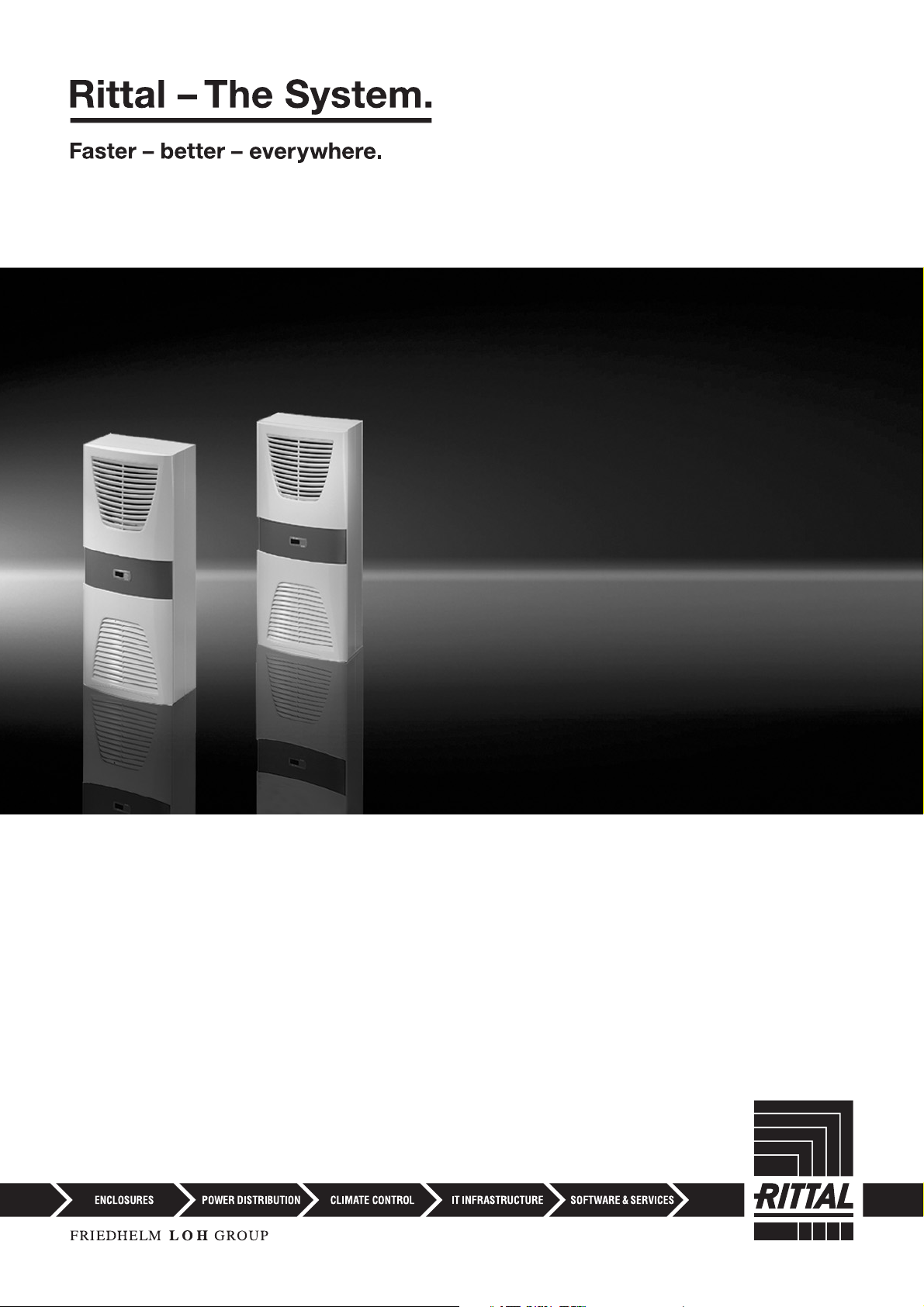
Enclosure cooling unit
Assembly and operating instructions
3302.xxx
3302.3xx
3303.xxx
3304.xxx
3305.xxx
3328.xxx
3329.xxx
3332.xxx
3361.xxx
3366.xxx
Page 2

Contents
EN
Contents
1 Notes on documentation .................. 3
1.1 CE labelling .................................................. 3
1.2 Storing the documents................................. 3
1.3 Symbols used in these operating instructions 3
1.4 Other applicable documents ........................ 3
2 Safety notes ..................................... 3
3 Device description ............................ 4
3.1 TÜV-tested output measurement to
DIN EN 14511 .............................................. 4
3.2 Functional description .................................. 4
3.2.1 How it works ......................................................... 4
3.2.2 Control .................................................................. 5
3.2.3 Bus mode (e-Comfort controller only) .................... 5
3.2.4 Safety devices ....................................................... 5
3.2.5 Condensation ....................................................... 5
3.2.6 Filter mats ............................................................. 5
3.2.7 Door limit switch ................................................... 5
3.2.8 Additional interface X3 .......................................... 6
3.3 Proper use, foreseeable misuse ................... 6
3.4 Scope of supply........................................... 6
4 Assembly and connection ................ 6
4.1 Choosing the installation site........................ 6
4.2 Notes on assembly ...................................... 6
4.2.1 General ................................................................. 6
4.2.2 Layout of the electronic components in the
enclosure .............................................................. 7
4.3 Fitting the cooling unit.................................. 7
4.3.1 Making the cut-outs .............................................. 8
4.3.2 External mounting of the cooling unit ..................... 8
4.3.3 Partial internal mounting of the cooling unit ........... 8
4.3.4 Full internal mounting of the cooling unit ................ 9
4.4 Connecting the condensate discharge....... 10
4.5 Notes on electrical installation .................... 11
4.5.1 Connection data ................................................. 11
4.5.2 Overvoltage protection and supply line load ........ 11
4.5.3 Three-phase devices ........................................... 11
4.5.4 Door limit switch ................................................. 11
4.5.5 Notes on the flicker standard .............................. 11
4.5.6 Potential equalisation .......................................... 12
4.6 Making the electrical connection ................ 12
4.6.1 Bus connection (only when interconnecting several
units with a Comfort controller) ............................ 12
4.6.2 Connection X3 for serial interface ........................ 12
4.6.3 Mounting external transformer ............................. 12
4.6.4 Installing the power supply .................................. 13
4.7 Finalising assembly .................................... 15
4.7.1 Installing the filter media ...................................... 15
4.7.2 Fitting the cooling unit ......................................... 15
4.7.3 Setting the filter mat monitor (only with e-Comfort
controller) ............................................................ 16
6 Operation ....................................... 16
6.1 Control using the Basic controller............... 16
6.1.1 Properties ........................................................... 16
6.1.2 Operating and error display ................................. 17
6.1.3 Test mode with the Basic controller .................... 18
6.1.4 Setting the temperature ...................................... 18
6.1.5 Resetting the Basic controller .............................. 18
6.2 Control using the e-Comfort controller........ 18
6.2.1 Properties ........................................................... 19
6.2.2 Eco mode ........................................................... 19
6.2.3 Launching test mode .......................................... 19
6.2.4 General information about programming ............. 20
6.2.5 Editable parameters ............................................ 21
6.2.6 Programming overview ....................................... 22
6.2.7 Defining system messages for evaluation ............ 23
6.2.8 Setting the master/slave identifier ........................ 24
6.2.9 Evaluating system messages .............................. 24
6.2.10 Reset the e-Comfort controller ............................ 26
7 Inspection and maintenance .......... 26
7.1 Compressed air cleaning 3304.xxx,
3305.xxx .................................................... 26
7.2 Compressed air cleaning 3328.xxx,
3329.xxx, 3332.xxx .................................... 30
7.3 Installation instructions for NEMA 4X
devices ...................................................... 35
8 Storage and disposal ..................... 36
9 Technical details ............................ 36
9.1 Technical specifications.............................. 36
9.2 Performance diagrams ............................... 43
10 List of spare parts .......................... 44
11 Appendix ....................................... 47
11.1 Cut-out and hole sizes ............................... 47
11.1.1 Dimensions for external mounting ....................... 47
11.1.2 Dimensions for partial internal mounting .............. 50
11.1.3 Dimensions for full internal mounting ................... 51
11.2 Electrical wiring plan................................... 52
5 Start-up .......................................... 16
2 Rittal enclosure cooling unit
Page 3
1 Notes on documentation
1 Notes on documentation
1.1 CE labelling
Rittal GmbH & Co. KG confirms the conformity of the
cooling unit with the European Union's Machinery Directive 2006/42/EC and EMC Directive 2014/30/EC. A
corresponding declaration of conformity has been issued. This can be found at the end of this document, or
on the Rittal homepage.
1.2 Storing the documents
The assembly and operating instructions as well as all
other applicable documents are an integral part of the
product. They must be issued to everyone who works
with the unit and must always be available and on hand
for operating and maintenance personnel.
1.3 Symbols used in these operating instructions
The following symbols are used in this documentation:
Danger!
A dangerous situation in which failure to
comply with the instructions will result in
death or severe injury.
Warning!
A dangerous situation which may cause
death or serious injury if the instructions
are not followed.
Caution!
A dangerous situation which may lead to
(minor) injuries if the instructions are not
followed.
Note:
Important notices and indication of situations
which may result in material damage.
This symbol indicates an "action point" and shows that
you should perform an operation or procedure.
2 Safety notes
Please observe the following general safety notes when
assembling and operating the unit:
– Assembly, installation and servicing may only be per-
formed by properly trained specialists.
– Screw the enclosure to the floor to prevent it from tip-
ping over when the cooling unit is installed.
– Do not obstruct the air inlet and air outlet of the cooling
unit inside and outside the enclosure (see section4.2.2 "Layout of the electronic components in the
enclosure").
– To ensure problem-free opening and closing of the en-
closure door, use a ride-up door roller (refer to the accessories in the Rittal Catalogue). This raises the door
slightly and balances out the weight of the cooling unit,
to prevent buckling of the door and associated seal
problems.
– The heat loss of the components installed in the enclo-
sure must not exceed the useful cooling power of the
cooling unit.
– Cooling units with item numbers: 3303.xxx, 3361.xxx,
3304.xxx, 3305.xxx, 3328.xxx, 3329.xxx and
3332.xxx must be transported in an upright position
and protected from tipping over.
– Units with item numbers 3302.xxx and 3366.xxx must
be transported lying flat.
– Shipping braces must be used when transporting a
unit that has already been mounted (on the enclosure).
A wooden structure made from square timbers or
boards to support the cooling unit at the bottom (see
fig. 1) is suitable for this purpose. The pallet should be
big enough to prevent the enclosure and cooling unit
overturning. If the cooling unit is mounted on a door,
ensure the door is kept closed during transport.
– Use only original spare parts and accessories
– Do not make any changes to the cooling unit other
than those described in these instructions or associat-
ed instructions.
– Risk of burns! On cooling units with automatic con-
densate evaporation, the surface of the thermal ele-
ment will get very hot during operation, and will remain
so for some time afterwards.
– The mains connector of the cooling unit must only be
connected and disconnected with the system de-en-
ergised. Connect the protective device specified on
the rating plate.
EN
1.4 Other applicable documents
Assembly and operating instructions in paper and digital
format are available for the unit types described here.
We cannot accept any liability for damage associated
with failure to observe these instructions. Where applicable, the instructions for any accessories used also apply.
Rittal enclosure cooling unit 3
Page 4
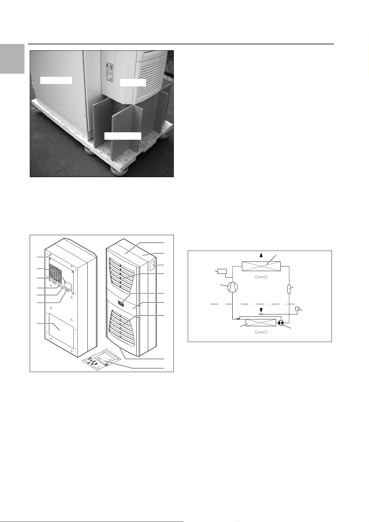
EN
Enclosure
Support
Cooling unit
10
9
8
11
13
12
16
15
14
1
2
4
5
6
7
3
PSAH-
Pressure
switch
Condenser fan
Expansion valve (4)
Temperature
control
Filter dryer (5)
Internal circuit
Compressor (2)
External circuit
Evaporator fan
Evaporator coil (1)
Condenser (3)
3 Device description
Fig. 1: Transporting an enclosure/cooling unit combination
3 Device description
Depending on the model chosen, your cooling unit may
vary in appearance from the illustrations contained in
these instructions. However, the functions are identical
in principle.
15 Condensate discharge
16 Dispatch bag
3.1 TÜV-tested output measurement to DIN EN 14511
All TopTherm cooling units in the output range from 300
to 4000 W are tested to the latest EN 14511-1-4:201312 standard by independent test institute TÜV Nord.
This means you have peace of mind about the design of
the climate control solution and you can be sure you are
getting the performance you are paying for.
3.2 Functional description
3.2.1 How it works
The cooling unit (compression refrigeration system)
comprises four main components (see fig. 3): the evaporator (1), the refrigerant compressor (2), the condenser
(3), and the control or expansion valve (4), which are
connected by suitable pipework. This circuit is filled with
a readily boiling substance, the refrigerant. The refrigerant R134a (CH
tion Potential (ODP) is 0, making it very eco-friendly. A filter dryer (5) which is integrated into the hermetically
sealed cooling circuit provides effective protection
against moisture, acid, dirt particles, and foreign bodies
within the cooling circuit.
FCF3) is chlorine-free. Its Ozone Deple-
2
Fig. 2: Device description
Key
1 Blind rivet nut
2Evaporator fan
3 Electrical wiring plan
4 X2 master-slave connection
5 X3 optional serial interface
6 X1 terminal strip
7 Air outlet hole
8 Front half of the enclosure
9 Rear half of the enclosure
10 Louvred grille for air outlet
11 Display
12 Infill panel
13 Louvred grille for air inlet
14 Rating plate
4 Rittal enclosure cooling unit
Fig. 3: Cooling circuit
In the evaporator coil (1), the liquid refrigerant is converted to a gaseous state. The energy needed for this purpose is taken from the enclosure air in the form of heat,
which has the effect of cooling the enclosure air. In the
compressor (2), the refrigerant is heavily compressed,
so that it achieves a higher temperature inside the condenser (3) than the ambient air. This means that excess
heat may be emitted to the ambient air via the surface of
the condenser, as a result of which the temperature of
the refrigerant drops and it is converted back into liquid.
It is re-injected into the evaporator coil via a thermostatic
expansion valve (4), which causes it to cool down further, and is then once again able to absorb the energy
from the enclosure air in the evaporator coil. The whole
cycle begins again.
Page 5

3 Device description
3.2.2 Control
Rittal enclosure cooling units are fitted with a controller
for setting the functions of the cooling unit.
Depending on the design, this is either a Basic controller
(operating status display via LED) or an e-Comfort controller (display plus extended functions, see section6
"Operation").
3.2.3 Bus mode (e-Comfort controller only)
The serial unit interface X2 allows you to create a bus
connection with up to ten cooling units using the masterslave cable (shielded, four-wire cable, Model No.
3124.100). This allows you to implement the following
functions:
– Parallel unit control (the cooling units in the network
can be switched on and off simultaneously)
– Parallel door status message ("door open")
– Parallel collective fault message
Data is exchanged via the master-slave connection.
During commissioning, assign an address to each unit
that also includes the identifier "master" or "slave".
3.2.4 Safety devices
– In the cooling cycle, the cooling units (with the excep-
tion of type 3302.xxx) have a tested pressure switch to
EN 12 263 which is set to maximum PS (permissible
pressure); this operates via an automatic reset device
whenever the pressure drops again
– Temperature monitoring prevents the evaporator coil
from icing over. If there is a risk of icing, the compres-
sor switches itself off and automatically switches itself
back on again at higher temperatures
– The refrigerant compressor and the fans are equipped
with thermal winding shields to protect against excess
current and excess temperatures
– In order to allow a reduction of pressure inside the
compressor and hence a safe restart, once it has been
switched off (e.g. upon reaching the set temperature
via the door limit switch function or via de-energising),
the device will switch back on with a delay of 180 sec-
onds
– The device has floating contacts on the connection
pins (terminals 3 – 5), via which system messages
from the device may be polled, e.g. using a PLC (1 x
change-over contact Basic controller, 2 x normally
open contacts e-Comfort controller)
3.2.5 Condensation
At high levels of humidity and low temperatures inside
the enclosure, condensation may form on the evaporator coil.
The cooling units (except 3302.xxx, 3303.xxx and
3361.xxx) have automatic, electric condensate evaporation. The thermal component used for this purpose is
based on self-regulating PTC technology. Condensate
arising on the evaporator coil is collected in a tank in the
external circuit of the cooling unit, and partially evaporated via the airflow. When the water level rises, the water
enters the PTC thermal component and is evaporated
(through-flow heater principle). The water vapour
streams out of the cooling unit with the airflow from the
external fan.
The PTC thermal component is permanently connected
and has no switchpoint. It is protected against short-circuits with miniature fuses (F1.1, F1.2). If the fuse has
tripped, any condensation is drained off via the safety
overflow.
For unit types 3302.xxx, 3303.xxx and 3361.xxx, the
condensate is routed downwards out of the unit via a
drain pipe on the evaporator coil divider panel. For this
purpose, a hose must be connected to the condensate
nozzle (see section4.4 "Connecting the condensate
discharge"). External condensate evaporators are available as accessories for these unit types (refer also to the
accessories in the Rittal Catalogue).
3.2.6 Filter mats
The entire cooling unit condenser is covered with a dirtrepelling, easy-to-clean RiNano coating. In many applications, therefore, the use of filter media is unnecessary,
particularly with dry dusts.
For dry, coarse dust and lint in the ambient air, we recommend installing an additional PU foam filter mat (available as an accessory) in the cooling unit. Depending on
the incidence of dust, you will need to replace the filter
mat from time to time.
For air containing oil condensate, we recommend the
use of metal filters (also available as an accessory).
These may be cleaned with suitable detergents and reused.
Function of the filter mat monitor (with e-Comfort controller only):
Dirt on the filter mat is automatically determined by
measuring the temperature difference in the external circuit of the cooling unit. As the level of filter mat soiling increases, the temperature difference will increase. The
setpoint value of the temperature difference in the external circuit adapts automatically to the relevant operating
points in the performance diagrams. Hence there is no
need to readjust the setpoint value for different unit operating points.
3.2.7 Door limit switch
The cooling unit may be operated with a floating door
limit switch connected. The door limit switch is not included with the supply (available as an accessory, Model
No. 4127.010).
The door limit switch function causes the fans and the
compressor in the cooling unit to be switched off after
approximately 15 seconds when the enclosure door is
opened (contacts 1 and 2 closed). This prevents the formation of condensation inside the enclosure while the
enclosure door is open. In order to prevent damage to
the unit, it is equipped with an ON delay: The evaporator
fan cuts back in with a delay of approximately 15 seconds after the door has been closed, while the condens-
EN
Rittal enclosure cooling unit 5
Page 6
4 Assembly and connection
EN
er fan and compressor switch on after approximately
3minutes.
Note:
– No external voltage may be applied to the
door contacts (terminals 1 and 2).
– For cooling units with basic control, the
evaporator fan continues to run even
when the door is open.
3.2.8 Additional interface X3
Note:
The electrical signals at the interface are of
an extra-low voltage (not extra-low safety
voltages to EN 60 335).
An additional interface card may be connected to the 9pole SUB-D connector X3 in order to incorporate the
cooling unit into higher-level monitoring systems (available as an accessory, interface card Model No.
3124.200).
3.3 Proper use, foreseeable misuse
The cooling unit is only intended for cooling connected
enclosures. Any other use is not permitted.
– The unit must not be installed and operated in loca-
tions which are accessible to the general public (see
DIN EN 60335-2-40, paragraph 3.119).
– The unit is designed solely for stationary use.
The cooling unit is state of the art and built according to
recognised safety regulations. Nevertheless, improper
use can pose a threat to the life and limb of the user or
third parties, or result in possible damage to the system
and other property.
Consequently, the cooling unit must only be used properly and in a technically sound condition! Any malfunctions which impair safety should be rectified immediately.
– Use of accessories not approved by Rittal GmbH &
Co. KG.
3.4 Scope of supply
The unit is supplied in a packaging unit in a fully assembled state.
Please check the scope of supply for completeness.
Qty. Description
1 Enclosure cooling unit
1
1
1
1
4 – 10
1 Drilling template
Tab. 1: Scope of supply
Dispatch bag:
– Assembly and operating instructions
–Self-adhesive tape
– Connector X1
–Grub screws
– Nuts, washers
4 Assembly and connection
4.1 Choosing the installation site
When choosing the installation site for the enclosure,
please observe the following:
– The site for the enclosure, and hence the arrangement
of the cooling unit, must be carefully selected so as to
ensure good ventilation (clearance between units and
clearance between the unit and the wall must be at
least 200 mm in each case).
– The cooling unit must be installed and operated in a
vertical position (maximum deviation: 2°).
– The installation site must be free from excessive dirt,
aggressive ambient conditions and moisture.
– The ambient temperature must be within the limits
specified on the rating plate.
– It must be possible to fit a condensate discharge (see
section4.4 "Connecting the condensate discharge").
– The mains connection data as stated on the rating
plate of the unit must be guaranteed.
Proper use also includes the observance of the documentation provided, and compliance with the inspection
and maintenance conditions.
Rittal GmbH & Co. KG is not liable for any damage which
may result from failure to comply with the documentation provided. The same applies to failure to comply with
the valid documentation for any accessories used.
Inappropriate use may be dangerous. Examples of inappropriate include:
– Use of the cooling unit over long periods with the en-
closure open.
– Use of impermissible tools.
– Improper operation.
– Improper rectification of malfunctions.
6 Rittal enclosure cooling unit
4.2 Notes on assembly
4.2.1 General
– Check the packaging carefully for signs of damage.
Traces of oil on damaged packaging are an indication
of refrigerant loss and leakages. Any packaging damage may be the cause of a subsequent functional failure.
– The enclosure must be sealed on all sides (IP 54). In-
creased condensation will occur if the enclosure is not
airtight.
– In order to avoid excessive condensation inside the
enclosure, we recommend installing a door limit
switch (e.g. 4127.010) which deactivates the cooling
unit when the enclosure door is opened (see section3.2.7 "Door limit switch").
Page 7
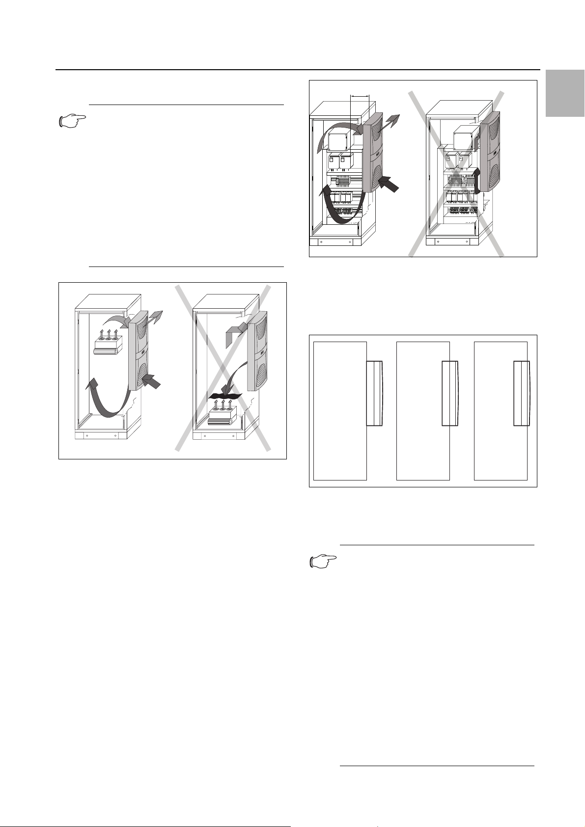
4.2.2 Layout of the electronic components in the
x
123
enclosure
Note:
Risk of condensation!
When arranging the electronic components
inside the enclosure, please ensure that the
cold airflow from the cooling unit is not directed at active components. Please also
ensure that the cold airflow is not directed at
the warm exhaust airflow from active components such as converters. This may lead
to an air short-circuit and therefore prevent
adequate climate control, or may even
cause the cooling unit’s internal safety devices to cease cooling operation.
4 Assembly and connection
EN
Fig. 5: Air circulation inside the enclosure
4.3 Fitting the cooling unit
The enclosure cooling unit may optionally be externally
mounted on the enclosure (1), partially internally mounted (2) or fully internally mounted (3):
Fig. 4: Never direct the cold airflow at active components
Air diversion components are available as accessories –
please refer to the Rittal Catalogue.
It is important to ensure even air circulation inside the enclosure. Under no circumstances should air inlet and
outlet openings be obstructed, otherwise the cooling
performance of the unit will be reduced. Ensure the distance "x" (see fig. 5) from components and other installed enclosures so that the required air circulation is
not obstructed and prevented.
Fig. 6: Installation method
To this end, cut the side panel or door of the enclosure
as per the drilling template included with the supply, and
drill the relevant holes.
Note:
Units of type 3302.xxx and 3366.xxx can
only be either externally mounted or fully internally mounted.
Units of type 3332.xxx can only be either externally mounted or partially internally
mounted; they cannot be mounted in lockable doors on 600/1200 wide TS enclosures.
To mount units 3328.xxx, 3329.xxx and
3332.xxx in the TS side or rear panel, we
recommend using enclosure panel fasteners 8800.071 (see Rittal Catalogue). For
high dynamic loads and mounting on the
enclosure door, we recommend using reinforced door hinges 8800.710 (see Rittal
Catalogue). Units with protection category
NEMA 4X are only suitable for external
mounting.
Rittal enclosure cooling unit 7
Page 8
EN
4 Assembly and connection
4.3.1 Making the cut-outs
Affix the supplied drilling template to the side panel or
door of the enclosure using adhesive tape.
There are dimensioning lines on the drilling template to
suit the various installation options for your cooling unit.
Using the dimension drawings (see Appendix), identify
the valid lines and dimensions for your installation type
on the drilling template.
Caution!
Carefully deburr all drilled holes and
cut-outs to prevent injuries caused by
sharp edges.
Fig. 9: Securing the cooling unit (3302.1xx only "external
mounting")
Mark, drill and deburr the holes.
Make the cut-outs including the line width as per the
drilling template.
Deburr the cut-outs.
4.3.2 External mounting of the cooling unit
Cut the supplied sealing tape to the correct length and
stick it carefully along the back of the unit so that no
gaps are left at the joints.
Fig. 7: Applying the self-adhesive tape
Screw the supplied grub screws into the blind nuts on
the rear of the unit.
Secure the unit using the supplied washers and nuts.
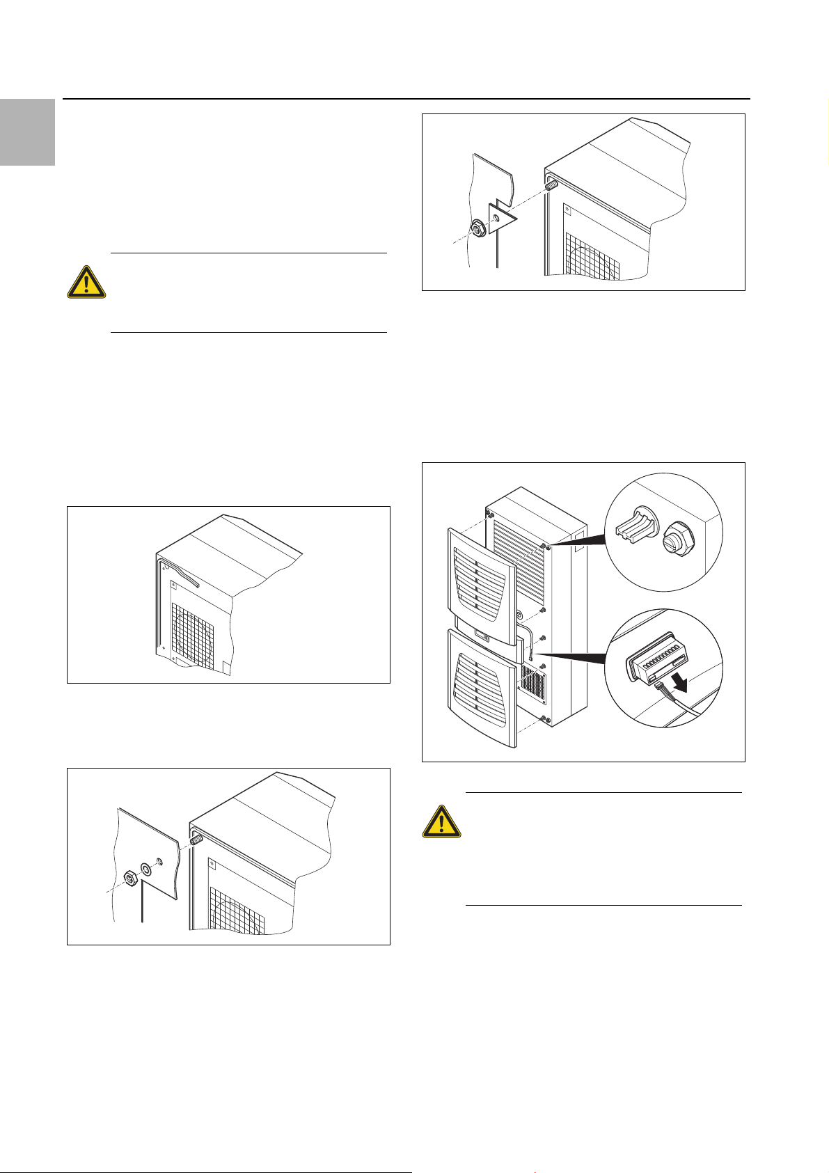
4.3.3 Partial internal mounting of the cooling unit
Carefully remove the louvred grille and, where applica-
ble, the infill panel, from the enclosure by pulling forwards.
Carefully disconnect the connector from the rear of the
display and gently push it inwards through the cable
gland.
Fig. 10: Removing the louvred grille & disconnecting the display
Caution!
Stability of the cooling unit is only guaranteed in its assembled state. Brace
the rear half of the enclosure to prevent
it from falling over before removing the
front half.
Loosen the four nuts on the front half of the enclosure
Fig. 8: Securing the cooling unit (all models except 3302.1xx)
and pull the enclosure forwards by approx. 5 cm.
Loosen the flat-pin connectors of the PE conductor
between the two enclosure halves.
Disconnect the fan connection.
Remove the front enclosure tray completely.
8 Rittal enclosure cooling unit
Page 9
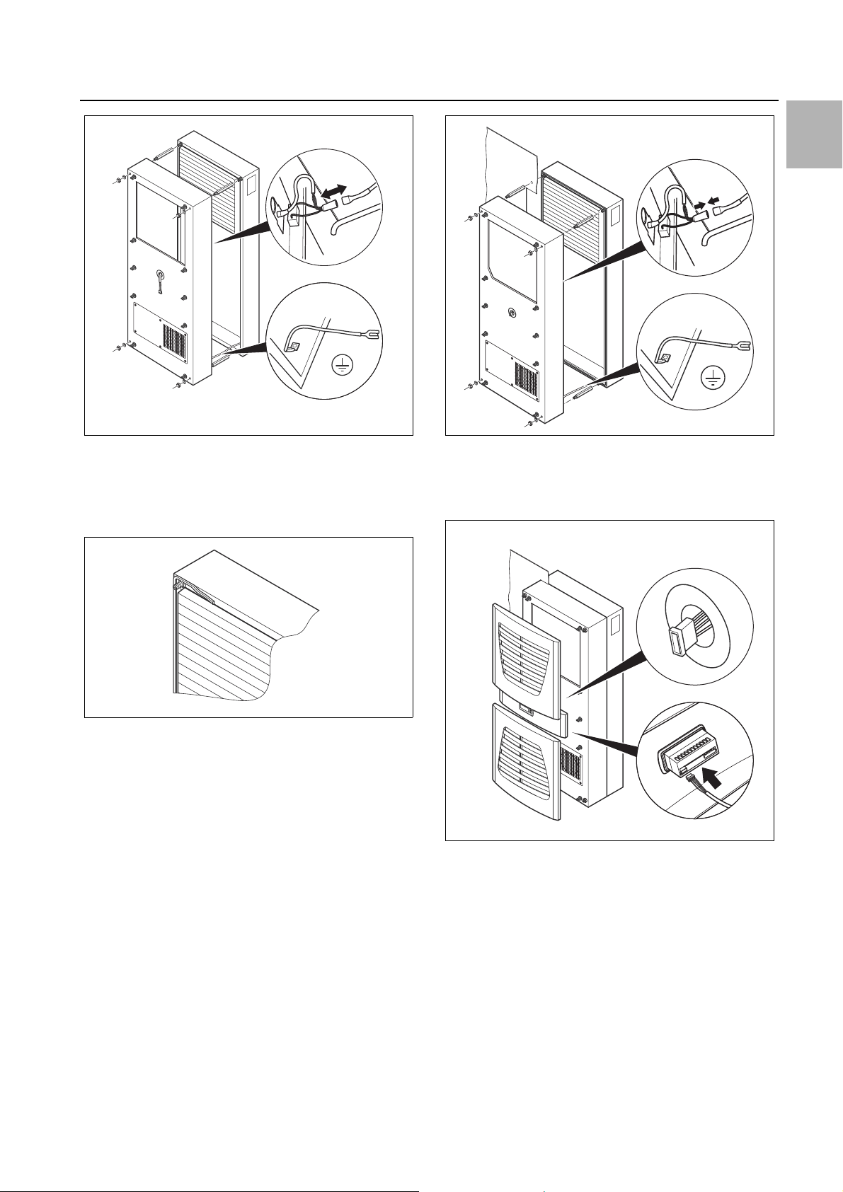
4 Assembly and connection
EN
Fig. 11: Removing the cover
Remove the four spacer bolts.
Cut the supplied sealing tape to the correct length and
stick it carefully along the inside of the rear enclosure
half so that no gaps are left at the connection points.
Fig. 12: Applying the self-adhesive tape
Push the rear enclosure half into the mounting cut-out
and secure it with the four spacer bolts.
Push the display cable through the cable gland of the
front enclosure half.
Fig. 13: Securing the cooling unit
Connect the fan connector and PE conductor.
Mount the front enclosure tray using the washers and
nuts.
Fig. 14: Connecting the display connector
Carefully connect the display connector.
Push the louvred grille and, where applicable, the infill
panel, onto the enclosure.
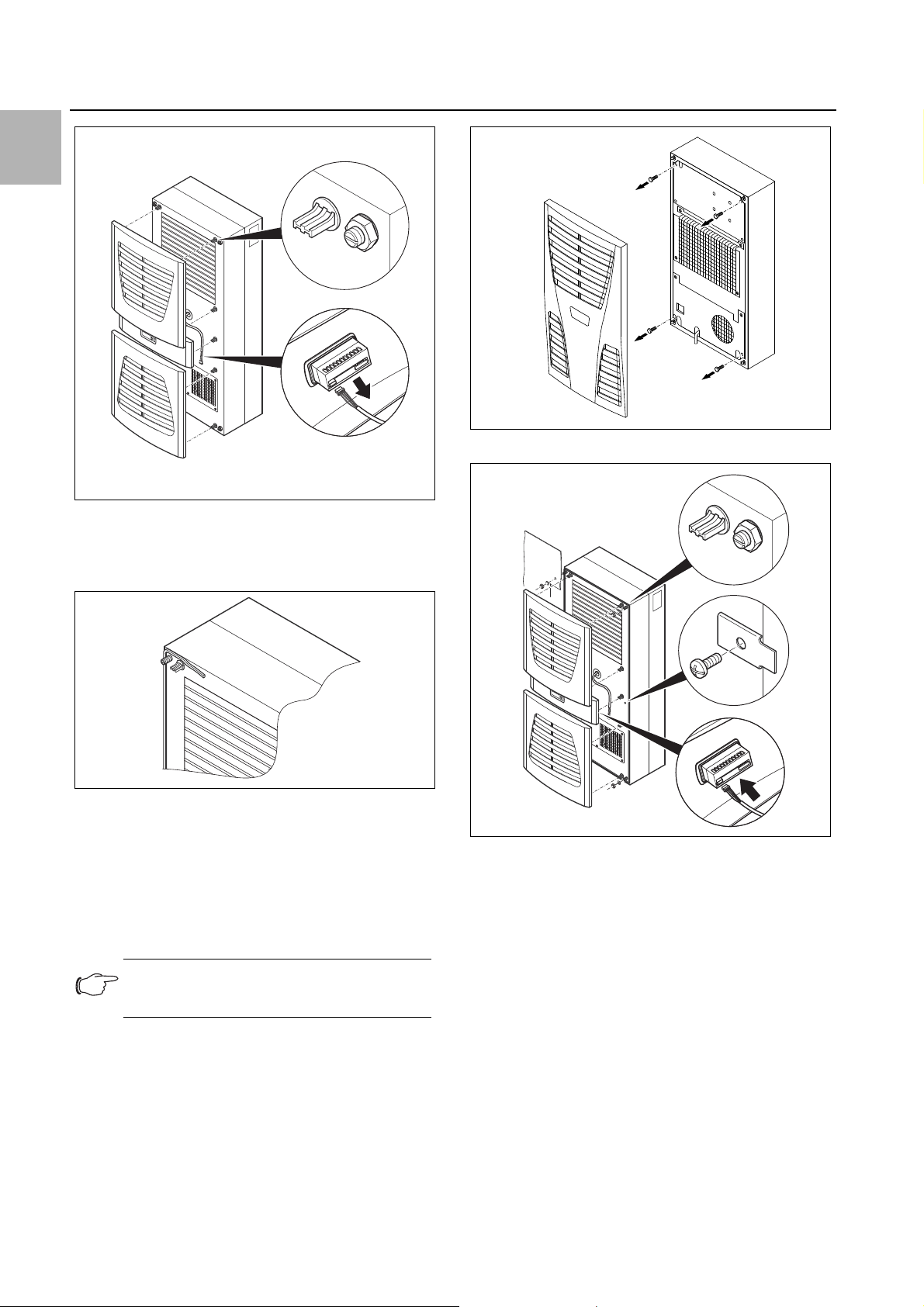
4.3.4 Full internal mounting of the cooling unit
Carefully remove the louvred grille and the infill panel
from the enclosure by pulling forwards.
Carefully disconnect the connector from the rear of the
display.
Rittal enclosure cooling unit 9
Page 10
EN
4x
4 Assembly and connection
Fig. 17: 3302.xxx only: removing the four screws
Fig. 15: Removing the louvred grille & disconnecting the display
Cut the supplied sealing tape to the correct length and
stick it carefully along the front enclosure half so that
no gaps are left at the connection points.
Fig. 16: Applying the self-adhesive tape
Loosen the four nuts and washers from the front en-
closure half.
Push the unit into the mounting cut-out from the inside
of the enclosure, and secure it to the enclosure from
the outside using the washers and nuts.
Only for 3302.xxx:
Fig. 18: Securing the cooling unit
Where necessary, additionally secure the unit using
the supplied mounting plates as shown in fig. 18.
Carefully connect the display connector.
Push the louvred grille and, where applicable, the infill
panel, onto the enclosure.
Note:
The tightening torque for the nuts is 6 Nm.
4.4 Connecting the condensate discharge
A condensate discharge hose can be fitted to all types
of cooling unit (except NEMA 4X devices).
Before installing, remove the four screws as shown.
The condensate discharge
– must be laid with a suitable and constant gradient (no
siphoning)
– must be laid without kinks
– must not have a reduced cross-section if extended
The condensate hose is available as an accessory (refer
also to Accessories in the Rittal Catalogue).
10 Rittal enclosure cooling unit
Page 11
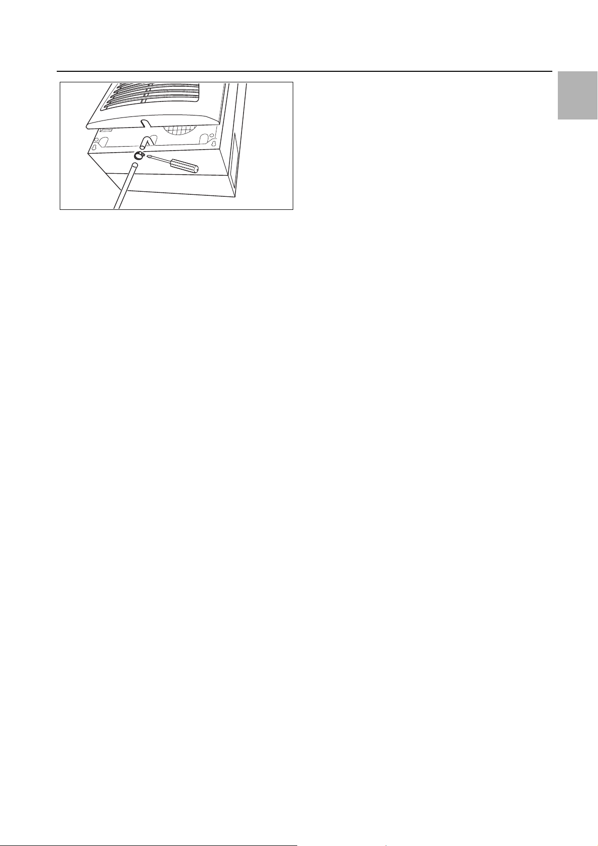
Fig. 19: Connecting the condensate discharge
Connect a suitable hose to the condensate nozzle and
secure using a hose clip.
Route the condensate hose to a drain or into the ex-
ternal condensate evaporator (refer to Accessories in
the Rittal Catalogue).
4.5 Notes on electrical installation
When performing the electrical installation, it is important
to observe all valid national and regional regulations as
well as the provisions of the responsible power supply
company. The electrical installation may only be carried
out by a qualified electrician who is responsible for compliance with the applicable standards and regulations.
4.5.1 Connection data
– The connected voltage and frequency must corre-
spond to the values stated on the rating plate
– The cooling unit must be connected to the mains via
an all-pin isolating device, which ensures at least
3 mm contact opening when switched off
– No additional temperature control may be connected
upstream of the unit at the supply end
– Install the protective device specified on the rating
plate to protect the line and equipment from short-circuits.
– The mains connection must ensure low-noise poten-
tial equalisation
4.5.2 Overvoltage protection and supply line load
– The unit does not have its own overvoltage protection.
Measures must be taken by the operator at the supply
end to ensure effective lightning and overvoltage protection. The mains voltage must not exceed a tolerance of ±10%.
– In accordance with IEC 61 000-3-11, the unit is in-
tended solely for use at sites with a continuous current-carrying capacity (incoming mains power supply)
of more than 100 A per phase and with a supply voltage of 400/230 V. If necessary, the electricity supply
company must be consulted to ensure that the continuous current-carrying capacity at the point of connection to the public grid is sufficient for connection of
such a unit.
– The fans and compressors in single- and three-phase
units are intrinsically safe (thermal winding protection).
This also applies to transformer versions, types
4 Assembly and connection
3304.510, 3305.510, 3328.510 and 3329.510, and to
special-voltage units which are likewise equipped with
a transformer.
– Install the protective device specified on the rating
plate to protect the line and equipment from short-circuits (miniature circuit-breaker with appropriate characteristic – e.g. "K" characteristic – or gG standard
type slow fuse, circuit-breaker for plant or transformer
protection). Select a suitable circuit-breaker in accordance with the information specified on the rating plate:
Set it to the minimum specified value. This will achieve
the best short-circuit protection for cables and equipment. Example: Specified setting range 6.3 – 10 A; set
to 6.3 A.
4.5.3 Three-phase devices
– The electrical connection for devices in the three-
phase version MUST be made with a clockwise rotating field
– The three-phase version of models 3304.xxx,
3305.xxx, 3328.xxx, 3329.xxx and 3332.xxx must be
connected to a TN network with star earthing via a circuit-breaker for plant protection (current setting as per
the rating plate). Three-phase units with special voltages must be protected with a circuit-breaker for
transformer protection (category AC-3) as per the rating plate.
– Units designed for three phase 400/460 V feature ad-
ditional monitoring of the rotary field or the absence of
a phase. If the rotary field is incorrect or a phase is absent, the unit will not run.
4.5.4 Door limit switch
– Each door limit switch must only be assigned to one
cooling unit.
– Several door limit switches may be connected in par-
allel to one cooling unit.
– The minimum cross-section for the connection cable
is 0.3 mm
– The line resistance to the door limit switch must not
exceed a maximum of 50 .
– The door limit switch only supports a floating connec-
tion; no external voltages.
– The contact of the door limit switch must be closed
when the door is open.
The safety extra-low voltage for the door limit switch is
provided by the internal power pack: Current approx.
30 mA DC.
Connect the door limit switch to terminals 1 and 2 of
the connector.
4.5.5 Notes on the flicker standard
The flicker limits specified in standard EN 61 000-3-3 or
-3-11 are adhered to, provided the supply impedance is
less than approx. 1.5 .
Where necessary, the unit operator should measure the
connected impedance or consult the responsible electricity supply company. If there is no way of influencing
2
for a cable length of 2 m.
EN
Rittal enclosure cooling unit 11
Page 12
EN
Mounting device
rear panel
Fastening to 35 mm
support rail
DIN EN 50 022
Mains connection for
Cooling unit
Customer-side
connection
230 V
4 Assembly and connection
the supply impedance and sensitive installed components (e.g. BUS) are subjected to interference, a line reactor or starting-current limiting device should be connected upstream of the cooling unit to restrict the startup current of the cooling unit.
4.5.6 Potential equalisation
If, for EMC reasons, the unit is to be integrated into the
customer’s existing potential equalisation system, a
conductor with a larger nominal cross-section can be
connected to the potential equalisation connection point
(attachment points) on the wall-mounted cooling units.
According to the standard, the PE conductor in the
mains connection cable is not classified as an equipotential bonding conductor.
4.6 Making the electrical connection
4.6.1 Bus connection (only when interconnecting several units with a Comfort controller)
When using several cooling units, the serial device interface X2 can be used to connect up to ten cooling units
with the bus cable (Model No. 3124.100).
Fig. 20: Mounting external transformer (3361.x40 only)
When interconnecting, please note the following:
– De-energise the cooling units to be connected
– Ensure proper electrical insulation
– Make sure the cables are not laid in parallel to power
– Make sure that the lines are short
4.6.2 Connection X3 for serial interface
The interface card (Model No. 3124.200) may be connected to X3. This is used to evaluate system messages
in a PLC, for remotely setting parameters and monitoring, or for integration into the facility management system.
lines
Note:
The electrical signals at the X2 interface are
of an extra-low voltage (not extra-low safety
voltages in accordance with EN 60 335-1).
Note:
With the last slave unit in the group, do not,
under any circumstances, connect the remaining socket of the Y cable 3124.100 into
interface X3 of the cooling unit!
4.6.3 Mounting external transformer
Only for 3361.x40.
12 Rittal enclosure cooling unit
Page 13
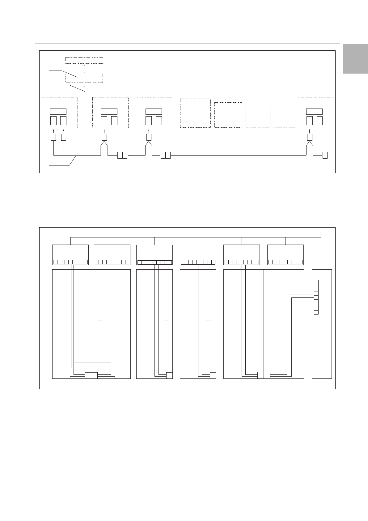
Fig. 21: Connection example: Master-slave operation
X2
CMC
I/O unit
RTT
Master
Adr.: 09
X1
X2
X3
X1
X2
X3
X1
X2
X3
X1
X2
X3
X2
X3
X2
X2
X2
X2
X2
X2
St. St. St.
Bu.
St.
Bu.
X2
Adr.: 11 Adr.: 12RTT
Slave
RTT
Slave
Adr.: 19RTT
Slave
St.
Bu.
St.
Bu.
3
2
1
X10
L1
L2
N
PE
1
2345
1
X10
X10 X10 X10 X10
X2 X2 X2 X2 X2 X2
X2
L1
PE
1
2345
L1
L2
N
PE
1
2345
L2 L3
L1
PE
1
2345
L2 L3
L1
PE
1
2345
L2 L3
L1
PE
1
2345
L2 L3
L1
L2
N
PE
1
23
4
5
X10
2
3
4
56
1
Adr.: 06 Adr.: 11 Adr.: 12 Adr.: 13 Adr.: 14 Adr.: 15
22 2 2 2
34432
Adr.: 16
Key
1 Serial interface (Model No. 3124.200)
2 Serial interface cable
3 Master-slave bus cable (Model No. 3124.100)
RTT Rittal TopTherm cooling units
X1 Supply connection/door limit switch/alarms
4 Assembly and connection
EN
X2 Master/slave connection Sub-D, 9-pole
X3 Serial interface Sub-D, 9-pole
St. Sub-D connector, 9-pole
Bu. Sub-D jack, 9-pole
Adr. Address
Fig. 22: Connection example: Door limit switch and master-slave operation
Key
1 Master cooling unit
2 Slave cooling units
3 2-door enclosure with two door limit switches
4 Enclosure with door limit switch
Rittal enclosure cooling unit 13
4.6.4 Installing the power supply
Complete the electrical installation by following the
wiring plan on the rear of the cooling unit (see fig. 2, for
key see page 15).
If you would like the system messages from the cool-
ing unit to be evaluated via the system message relay,
you should also connect a suitable low-voltage cable
to terminals 3 – 5.
Page 14
EN
3302.100/.110, 3302.300/.310
3303.500/.510, 3303.600/.610, 3361.500/.510, 3361.600/.610, 3361.540/.640
3304.500/.510/.504/.514/.520/.600/.610
3305.500/.510/.504/.514/.520, 3328.500/.510/.504/.514/.520, 3329.500/.510/.504/.514/.520,
3305.600/.610, 3328.600/.610, 3329.600/.610, 3366.500/.510/.600/.610
4 Assembly and connection
Fig. 23: Electrical wiring plan no. 1
Fig. 24: Electrical wiring plan no. 2
14 Rittal enclosure cooling unit
Page 15
4 Assembly and connection
3304.540/.544, 3305.540/.544, 3328.504/.544, 3329.504/.544
3304.640, 3305.640, 3328.640, 3329.640, 3366.540/.640, 3332.540/.640
EN
Fig. 25: Electrical wiring plan no. 3
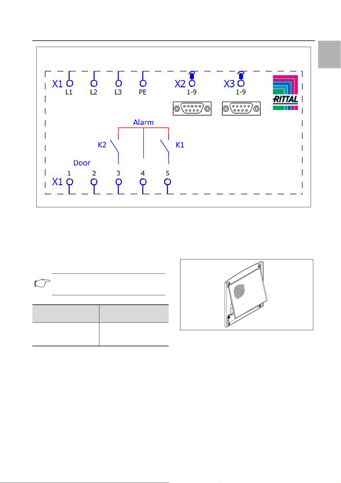
Key
X1 Main terminal strip
X2 Master/slave connection
X3 Optional interface
K1 Relay collective fault 1
K2 Relay collective fault 2
Door Door limit switch (without door limit switch: terminal 1, 2
open)
textile plants with heavy lint contamination, lint screens
should be used (available as an optional extra).
Pull the louvred air inlet grille off the enclosure.
Insert the filter mat into the louvred grille as shown in
fig. 26 and push it back onto the enclosure.
Note:
For technical data, refer to the rating plate.
AC
cos φ = 1
I max. = 2 A
U max. = 250 V
Tab. 2: Relay contact data
4.7 Finalising assembly
4.7.1 Installing the filter media
DC
Res. Load
I min. = 100 mA
U max. = 30 V
I max. = 2 A
Fig. 26: Installing the filter mat
4.7.2 Fitting the cooling unit
For partial and full internal mounting only.
Connect the connector to the rear of the display.
Place the louvred grille onto the unit at the front, and
press it down until you hear it snap into place.
The entire cooling unit condenser is covered with a dirtrepelling, easy-to-clean RiNano coating. In many applications, therefore, the use of filter media is unnecessary,
particularly with dry dusts.
For dry, coarse dust and lint in the ambient air, we recommend installing an additional PU foam filter mat (available as an accessory) in the cooling unit. For air containing oil condensate, we recommend the use of metal filters (also available as an accessory). When used in
Rittal enclosure cooling unit 15
Page 16
EN
34
1
2
5
5 Start-up
Fig. 27: Connect the display and attach the louvred grille
4.7.3 Setting the filter mat monitor (only with e-Comfort controller)
Function of the filter mat monitor:
Dirt on the filter mat is automatically detected by meas-
uring the temperature difference in the external circuit of
the cooling unit (see section6.2.6 "Programming overview"). As the level of filter mat soiling increases, the
temperature difference will increase. The setpoint value
of the temperature difference in the external circuit
adapts automatically to the relevant operating points in
the performance diagrams. Hence there is no need to
readjust the setpoint value for different unit operating
points.
5 Start-up
Note:
The oil must be collected in the compressor
in order to ensure effective lubrication and
cooling.
Do not operate the cooling unit for at least
30 minutes after assembling the equipment.
Once all the assembly and installation work is com-
plete, switch on the power supply to the cooling unit.
The cooling unit starts running:
– With Basic controller: The green operating LED ("line")
is illuminated.
– With e-Comfort controller: The software version of the
controller first appears for approx. 2 seconds, then
"ECO" to show Eco mode is enabled. The internal en-
closure temperature will then appear in the 7-segment
display
You can now make your individual settings on the unit,
e.g. set the temperature or (with e-Comfort controller
only) assign the network identifier, etc. (refer to section6
"Operation").
6 Operation
You can operate the cooling unit using the controller on
the front of the device (fig. 2, item 11). Depending on the
model, the unit is equipped with a Basic or e-Comfort
controller.
6.1 Control using the Basic controller
For Model Nos. 3302.xxx.
Fig. 28: Basic controller
Key
1 Controller trim panel
2 Temperature setter
3 LED green ("line")
4 LED red ("alarm")
5 Reset button
6.1.1 Properties
– Rated operating voltage: 115 V or 230 V
– Integral start-up delay and door limit switch function
– Protective function to prevent icing
– Monitoring of all motors (compressor, condenser fan,
evaporator fan)
– Phase monitoring for three-phase units
– Visualisation of the operating status via LED display:
– Voltage on, unit operational
– Door open (only if door limit switch installed)
– Warning of overtemperature
– High-pressure monitor has switched
– Switching hysteresis: 5 K
If the cooling unit and compressor run times are too
long < 1 minute, the switching hysteresis to protect
the cooling unit is automatically increased.
– Floating system message contact in case of overtem-
perature
16 Rittal enclosure cooling unit
Page 17
6 Operation
– Temperature setting
(setting range 30 – 55°C) via potentiometer
– Test function
– Flashing mode to indicate system messages.
See section6.1.2 "Operating and error display"
The cooling unit operates automatically, i.e. after switching on the power supply, the evaporator fan (see fig. 3)
will run continuously and permanently circulate the inter-
LED Status Cause Solution
Green
(line)
Red
(alarm)
Illuminated Power supply on,
unit operational
Flashing Only with door limit switch installed:
enclosure door open
Only with door limit switch installed:
enclosure door closed
Alarm/error/warning Number of flash
a
Implement
reset
Device reset (12) |_|_|_|_|_|_|_|_|_|_|_|*****|_|_|_|_|_|_|_|_|_|_|_|
High pressure alarm (0) |_|_|_|_|_|_|_|_|_|_|_|_|_|_|_|_|_|_|_|_|_|_|_|_|_|
nal enclosure air. The built-in Basic controller ensures
automatic normal shut-down operation of the cooling
unit by the value of the fixed preset switching difference
of 5 K.
6.1.2 Operating and error display
The Basic controller monitors and controls the cooling
unit. It indicates the operating and error status via the
green and red LEDs (fig. 28, items 3 and 4):
–
In order to avoid condensation, close the enclosure door as quickly as possible.
Check the position of the door limit switch.
Flash interval
intervals for the
red LED
EN
Sensors Potentiometer defective or
display error
Internal temperature
sensor defective
Anti-icing sensor defective (5) |_|_|_|_|*****|_|_|_|_|*****|_|_|_|_|*****|_|_|_|_|
Overload Compressor overloaded (6) |_|_|_|_|_|*****|_|_|_|_|_|*****|_|_|_|_|_|*****
Interior fan overloaded (7) |_|_|_|_|_|_|*****|_|_|_|_|_|_|*****|_|_|_|_|_|_|
Exterior fan overloaded (8) |_|_|_|_|_|_|_|*****|_|_|_|_|_|_|_|*****
Device status/state
Warning Anti-icing alarm (2) |_|*****|_|*****|_|*****|_|*****|_|*****|_|*****|_|
Off No display No power – Check power supply
Tab. 3: Operating and error display on the Basic controller
Overload mode
(heat loss)
Overtemperature warning (1) |*****|*****|*****|*****|*****|*****|*****|*****|*****|
Rotary current phase
toring:
"LED off" = Incorrect
phase connection
moni-
(3) |_|_|*****|_|_|*****|_|_|*****|_|_|*****|_|_|*****
(4) |_|_|_|*****|_|_|_|*****|_|_|_|*****|_|_|_|*****
(9) |_|_|_|_|_|_|_|_|*****|_|_|_|_|_|_|_|_|*****
– Swap phases
Key to flash intervals
| = 500 ms (red LED on)
_ = 500 ms (red LED off)
***** = 3 s pause (red LED off)
nection diagrams under section4.6.4 "Installing the
power supply"):
– Terminal 3: NC (normally closed)
– Terminal 4: C (connection of the supply voltage to the
fault signal relay)
The overtemperature message may also be polled via an
integral floating contact on the cooling unit terminal (system message relay with changeover contact, see con-
Rittal enclosure cooling unit 17
– Terminal 5: NO (normally open)
The NC and NO definitions refer to the de-energised
state. As soon as power is applied to the cooling unit,
Page 18
6 Operation
12
4
3
EN
the system message relay picks up, so that the relay
contacts change status (contact 3 – 4 open; contact 4 –
5 closed).
This is the normal operating state of the cooling unit. As
soon as an error message occurs or the power supply is
interrupted, the relay drops out and contact 3 – 4 is
closed.
6.1.3 Test mode with the Basic controller
The Basic controller is equipped with a test function
whereby the cooling unit commences cooling operation
independently of the set temperature or door limit switch
function.
First you must remove the controller trim panel.
Switch off the mains voltage.
Remove the louvred grille or infill panel in which the
controller is installed.
Release the display lock from behind and pull it for-
wards slightly.
6.1.4 Setting the temperature
Note:
With the Basic controller, the temperature is
preset at the factory to +35°C.
In order to save energy, do not set the temperature lower than that actually necessary.
To change the temperature setting:
Take the trim panel off the controller as described in
section6.1.3 "Test mode with the Basic controller".
Set the required temperature on the temperature set-
ting device (fig. 28).
Carefully push the trim panel onto the display until you
hear it snap into place.
Push the display back into the infill panel or louvred
grille.
Re-attach the louvred grille or infill panel to the cooling
unit.
6.1.5 Resetting the Basic controller
Following a high-pressure alarm in the cooling cycle, and
once the cause has been rectified, you will need to manually reset the Basic controller:
Take the trim panel off the Basic controller as de-
scribed in section6.1.3 "Test mode with the Basic
controller".
Press the reset button (fig. 28, item 5) for at least
3seconds.
The red LED is extinguished.
Re-install the Basic controller.
Fig. 29: Releasing the Basic controller trim panel
Carefully lift the trim panel, e.g. using your thumb or a
flat screwdriver, and remove it.
You can now start test mode.
Rotate the potentiometer to the left-hand stop, then
hold the rubberised potentiometer display down while
you re-connect the mains voltage.
The cooling unit will commence operation and the green
LED will flash (I_II_I_II_. ..). Test mode is completed after
approximately 5 minutes. The unit switches off and
changes to normal operation.
Key
I = LED 500 ms on
_ = LED 500 ms off
In normal operation, the green LED is permanently illuminated.
Next, rotate the potentiometer back to the required
setpoint.
6.2 Control using the e-Comfort controller
For unit types 33xx.5xx and 33xx.6xx.
Fig. 30: e-Comfort controller
Key
1 Programming button, also display of the set temperature
unit (degrees Celsius)
2 Set button
3 Programming button, also display of the set temperature
unit (degrees Fahrenheit)
47-segment display
18 Rittal enclosure cooling unit
Page 19

6 Operation
ON
Status
internal fan
Internal
temperature
Time
Setpoint
-5°C
Setpoint
-10°C
OFF
10 min.
30 sec.
10 min.
6.2.1 Properties
– Rated operating voltage:
–115 V or
–230 V or
– 400/460 V, 3-phase, supports multiple voltages
without rewiring
– Integral start-up delay and door limit switch function
– Protective function to prevent icing
– Monitoring of all motors (compressor, condenser fan,
evaporator fan)
– Phase monitoring for three-phase units
– Master-slave function with a maximum of ten units.
One device functions as a master unit. Once the set
temperature is reached by one of the connected slave
devices or in the event of the door limit switch function,
the affected slave unit will report to the master unit that
switches all the other cooling units on or off as re-
quired.
– Switching hysteresis: adjustable from 2 – 10 K, preset
to 5 K
– Visualisation of the current internal enclosure temper-
ature and all error messages in the 7-segment display
– Using an interface card (Model No. 3124.200), the unit
may be incorporated into higher-level remote monitor-
ing systems.
The cooling unit operates automatically, i.e. after switching on the power supply, the evaporator fan (see fig. 3)
will run and circulate the internal enclosure air. The compressor and condenser fan are regulated by the e-Comfort controller. The e-Comfort controller has a 7-segment display (fig. 30, item 4). After switching on the power supply, the current software version initially appears
on this display for approx. 2 seconds together with the
symbol to show Eco mode is enabled, followed by a preset option (e.g. t10) or the temperature.
In regular operation, the display shows both the temperature (in degrees Celsius or Fahrenheit – users may
switch between the two) and any error messages.
The current internal enclosure temperature is usually displayed permanently. In the event of an error message,
this alternates with the temperature display.
The unit is programmed using buttons 1 – 3 (fig. 30). The
relevant parameters also appear in the display.
6.2.2 Eco mode
All Rittal TopTherm cooling units with e-Comfort controller from firmware 3.2 have the energy-saving eco mode,
which is enabled in the delivered state.
The eco mode is used to save energy in the heat exchanger if there is no thermal load, or there is a low thermal load in the enclosure (e. g. standby operation, no
production or weekend). During this process the evaporator fan in the internal circuit is switched off as appropriate if the actual internal enclosure temperature drops
to 10 K below the specified setpoint temperature. To ensure the internal temperature is reliably measured during
this process, the fan starts cyclically for 30 sec. every 10
minutes (see fig. 31). If the internal temperature drops to
a range 5 K below the setpoint set again, the fan switches back to continuous operation.
If required, eco mode can be disabled on the control display. For this purpose switch the parameter from 1 to 0
in the programming level (see tab.4). The fan then runs
continuously.
Fig. 31: Eco mode
6.2.3 Launching test mode
The e-Comfort controller is equipped with a test function
whereby the cooling unit commences cooling operation
independently of the set temperature or door limit switch
function.
Simultaneously press buttons 1 and 2 (fig. 30) for at
least 5 sec.
The cooling unit will commence operation. Test mode is
completed after approximately 5 minutes. The unit
switches off and changes to normal operation.
EN
Rittal enclosure cooling unit 19
Page 20

6 Operation
EN
6.2.4 General information about programming
Using buttons 1, 2 and 3 (fig. 30) you can change
24 parameters within the preset ranges (min. value,
max. value).
Tables 4 and 5 show the parameters which can be altered. fig. 32 on page 22 shows which buttons must be
pressed.
Note on switching hysteresis:
With a low hysteresis and short switching
cycles, there is a risk that cooling may not
be adequate or that only partial sections of
the enclosure are cooled. If the cooling unit
and compressor run times are too long
< 1 minute, the switching hysteresis to protect the cooling unit is automatically increased (see message "LH" in section
6.2.9 "Evaluating system messages").
Note on temperature settings:
With the e-Comfort controller, the temperature is preset at the factory to +35°C.
In order to save energy, and due to the risk
of increased condensation, do not set the
temperature lower than that actually necessary.
Press one of the programming buttons (°C) or
(°F) until the required value appears.
Press button 2 ("Set") to confirm the change.
You can now alter other parameters in the same way.
There is no need to re-enter the authorisation code "22".
To exit programming mode, press button 2 ("Set")
again for approximately 5 seconds.
"Acc" will appear in the display to indicate that the
changes have been saved. The display then switches
back to regular operation (internal enclosure temperature).
You can also program the e-Comfort controller using a
diagnosis software package (Model No. 3159.100),
which is supplied with a connection cable to the PC. The
cable connector on the rear of the e-Comfort controller
display serves as an interface.
Note on useful cooling power:
Interactive performance diagrams for calculating the useful cooling power may be
found at www.rittal.com.
In principle, the programming is identical for all editable
parameters.
To enter programming mode:
Press button 2 ("Set") for approx. 5 seconds.
The controller is now in programming mode. While in
programming mode, if you do not press any buttons for
approx. 30 seconds, the display will first flash, then the
controller will switch back to normal display mode. "Esc"
in the display indicates that any changes made have not
been saved.
Press the programming buttons (°C) or (°F) to
switch between the editable parameters (see tables 4
and 5).
Press button 2 ("Set") to select the displayed parame-
ter for editing.
The current value of this parameter is displayed.
Press one of the programming buttons (°C) or
(°F).
"Cod" will appear in the display. In order to be able to
change a value, you must enter the authorisation code
"22".
Keep the programming button (°C) held down until
"22" appears.
Press button 2 ("Set") to confirm the code.
You can now alter the parameter within the preset limits.
20 Rittal enclosure cooling unit
Page 21

6.2.5 Editable parameters
See also fig. 32 on page 32.
6 Operation
EN
Progr.
level
1 St Internal enclosure
2 Fi Filter mat monitor-
3 Ad Master-slave iden-
4 CF Switch between
5 H1 Setting for switch-
6 H2 Differential for error
Display
screen
Parameter Min.
temperature setpoint T
i
ing
tifier
°C/°F
ing difference (hysteresis)
message A2
Max.
value
20°C 55°C 35°C The internal enclosure temperature setting is
68°F 131°F 95°F
10°C 60°C 99
18°F 108°F 178
0 19 0 See section 6.2.8 "Setting the master/slave
0 1 0 The temperature display can be switched be-
2 K 10 K 5 K The cooling unit is preset in the factory to a
4°F 18°F 9°F
3 K 15 K 5 K If the internal enclosure temperature exceeds
5°F 27°F 9°F
value
Factory
setting
(= off)
(= off)
Description
preset at the factory to 35°C (95°F) and may be
altered within a range of 20 – 55°C (68 – 131°F).
To enable filter mat monitoring, the display
should be set to a minimum of 10 K (18°F)
above the temperature difference shown in programming mode "Fi"; filter mat monitoring is disabled at the factory (99 = off).
identifier".
tween °C (0) and °F (1). The LED displays the
current unit of temperature.
switching hysteresis of 5 K (9°F). This parameter
should only be changed in consultation with us.
Please contact us for advice.
the set value by more than 5 K (9°F), then error
message A2 (internal enclosure temperature too
high) appears on the display terminal. If necessary, the differential may be altered here within
the range of 3 – 15 K (5 – 27°F).
26 ECO Eco-mode opera-
tion
27 PSO Changing the au-
thorisation code
Tab. 4: Editable parameters
0 1 1 Eco mode OFF: 0 / Eco mode ON: 1
0 15 0 This parameter allows you to change the "22"
authorisation code (factory setting).
The new code results from the sum of 22 +
PSO.
Rittal enclosure cooling unit 21
Page 22

EN
= 5 sec.
= 5 sec.
6 Operation
6.2.6 Programming overview
Fig. 32: Programming overview
22 Rittal enclosure cooling unit
Page 23

6 Operation
6.2.7 Defining system messages for evaluation
System messages are shown on the display screen of
the e-Comfort controller via the displays A1 to A20 and
E0.
Progr.
level
7 A1 0 2 0 Enclosure door open
8 A2 0 2 0 Internal temperature of enclosure too high
9 A3 020 Filter monitoring
10 A4 0 2 0 Ambient temperature too high/low
11A5 020 Icing hazard
12 A6 0 2 1 PSA
13 A7 0 2 2 Evaporator coil
14A8 021 Condensate warning
15 A9 0 2 1 Condenser fan blocked or defective
16 A10 0 2 1 Evaporator fan blocked or defective
17A11 022 Compressor
Display
screen
Min.
value
Max.
value
Factory
setting
Type or location of fault
A more detailed explanation of the system messages
may be found in section 6.2.9 "Evaluating system messages".
See also fig. 32 on page 22.
H
pressure switch
EN
18A12 021 Condenser
19 A13 0 2 1 Ambient temperature sensor
20 A14 0 2 1 Icing temperature sensor
21 A15 0 2 1 Condensate warning temperature sensor
22 A16 0 2 1 Internal temperature sensor
23 A17 0 2 1 Phase monitoring
24A18 020 EPROM
25A19 020 LAN/Master-Slave
Tab. 5: System messages that can be evaluated via relays
The system messages A1 – A19 may also be evaluated
via two floating system message relays. In this way, one
of the two system message relays may be allocated to
each system message.
System message relays with normally open contact, see
wiring diagrams in section 4.6.4 "Installing the power
The RiDiag II software (available as an accessory, Model
No. 3159.100) allows you to invert the system message
relay circuit.
In the normal operating state the two relays will then
drop out. If a system message occurs, the relevant relay
will energise and the contact will close.
supply":
– Terminal 3: NO (normally open, relay 2)
– Terminal 4: C (connection of the supply voltage to the
system message relay)
Note:
This setting can only be made using the
RiDiag II software.
– Terminal 5: NO (normally open, relay 1)
Program system messages with the value
The definition NO refers to the de-energised state. As
soon as power is applied to the cooling unit, both system message relays (relay 1 and 2) energise.
This is the normal operating state of the cooling unit. As
0: System message is not sent to the system mes-
sage relay, but merely appears in the display
1: System message is evaluated by relay 1
2: System message is evaluated by relay 2
soon as a system message occurs or the power supply
is interrupted, the corresponding relay will drop out and
open the contact.
Rittal enclosure cooling unit 23
Page 24

6 Operation
Master
02
Slave
11
Slave
12
EN
6.2.8 Setting the master/slave identifier
When several cooling units are connected together
(maximum ten), one of the cooling units must be defined
as the "master" and the others as "slaves". For this purpose, assign a corresponding identifier (address) to
each cooling unit which will enable the cooling unit to be
identified in the network.
If one of the slave units reaches the set temperature or if
the door limit switch function is activated, the affected
slave unit will report to the master unit, which then deactivates all the other cooling units.
Notes:
– Only one unit may be configured as mas-
ter, and its identifier must match
the number of connected slave units.
– The slave units must have different identi-
fiers.
– The identifiers must be numbered in as-
cending order without any gaps.
On the master cooling unit (00 = factory setting), set
the number of slave units present in the network:
– 01: Master with 1 slave cooling unit
– 02: Master with 2 slave cooling units
– 03: Master with 3 slave cooling units
– 04: Master with 4 slave cooling units
– 05: Master with 5 slave cooling units
– 06: Master with 6 slave cooling units
– 07: Master with 7 slave cooling units
– 08: Master with 8 slave cooling units
– 09: Master with 9 slave cooling units
On the slave cooling unit (00 = factory setting), set its
own address:
– 11: Slave cooling unit no. 1
– 12: Slave cooling unit no. 2
– 13: Slave cooling unit no. 3
– 14: Slave cooling unit no. 4
– 15: Slave cooling unit no. 5
– 16: Slave cooling unit no. 6
– 17: Slave cooling unit no. 7
– 18: Slave cooling unit no. 8
– 19: Slave cooling unit no. 9
Fig. 33: Master/slave connection (example)
For further connection examples, see section4.6.1 "Bus
connection (only when interconnecting several units with
a Comfort controller)".
For details of how to set the identifier, see section6.2.5
"Editable parameters" or section6.2.6 "Programming
overview", parameter "Ad".
6.2.9 Evaluating system messages
In the e-Comfort controller, system messages are indicated by a number in the display.
Following the appearance of messages A03, A06 and
A07 and after rectifying their cause, you will need to reset the e-Comfort controller (see section6.2.10 "Reset
the e-Comfort controller").
Display
screen
A01 Enclosure door open Door open or door limit switch incor-
A02 Internal temperature of
A03 Filter monitoring Filter mat soiled Clean or replace;
A04 Ambient temperature
A05 Icing hazard Operational display in case of icing haz-
Tab. 6: Troubleshooting with the e-Comfort controller
System message Possible cause Measures to rectify the fault
Close door, position door limit switch cor-
enclosure too high
too high/low
rectly positioned
Cooling capacity inadequate/unit undersized Error as a consequence of
messages A03 to A17.
Ambient temperature outside permissible operating range (+10°C to +60°C)
ard.
Evaporator coil fan may be mechanically blocked, defective, or cold air outlet obstructed.
rectly, check connection if necessary
Check cooling capacity
reset the e-Comfort controller
Raise or lower the ambient temperature (e.g.
heat or ventilate the room)
Set the enclosure interior temperature to a
higher value. Check the evaporator fan;
release or exchange if necessary.
24 Rittal enclosure cooling unit
Page 25

6 Operation
Display
screen
A06 PSAH pressure switch Ambient temperature too high Lower the ambient temperature;
A07 Evaporator coil Lack of refrigerant; sensor in front of or
A08 Condensate warning Condensate discharge kinked or
System message Possible cause Measures to rectify the fault
reset the e-Comfort controller
Condenser soiled Clean the condenser;
reset the e-Comfort controller
Filter mat soiled Clean or replace;
reset the e-Comfort controller
Condenser fan defective Replace;
reset the e-Comfort controller
E-valve defective Repair by refrigeration engineer;
reset the e-Comfort controller
H
pressure switch defective Refrigeration engineer to exchange
PSA
reset the e-Comfort controller
Repair by refrigeration engineer;
behind condenser defective
blocked
Only for units with optional condensate
evaporation
reset the e-Comfort controller
Check condensate drainage;
correct any kinks or blockages in the hose
Check the evaporation unit, replace if necessary
EN
A09 Condenser fan Blocked or defective Clear the blockage; replace if necessary
A10 Evaporator fan Blocked or defective Clear the blockage; replace if necessary
A11 Compressor Compressor overloaded (internal wind-
ing protection)
Defective (check by measuring the
winding resistance)
A12 Condenser tempera-
ture sensor
A13 Ambient temperature
sensor
A14 Icing temperature sen-
sor
A15 Condensate warning
temperature sensor
A16 Internal temperature
sensor
A17 Phase monitoring For three-phase devices only:
A18 EPROM error New board installed incorrectly Software update needed (only following
Open or short-circuit Replace
Open or short-circuit Replace
Open or short-circuit Replace
Open or short-circuit Replace
Open or short-circuit Replace
Incorrect rotary field/phase absent
No action required;
Unit switches on again independently
Replace by a refrigeration engineer
Swap two phases
board installation with more recent software): Enter the programming level with
Code 22;
press button 1 and confirm with "Set" until
"Acc" appears. Next, disconnect the unit
from the mains and reconnect.
A19 LAN/Master-Slave Master and slave not connected Check setting and/or cable
Tab. 6: Troubleshooting with the e-Comfort controller
Rittal enclosure cooling unit 25
Page 26

7 Inspection and maintenance
EN
Display
screen
A20 Voltage drop Error display not shown Event is stored in the log file
E0 Display message Connection problem between the dis-
OL Overload Ambient parameters or heat loss outside the applicable limits
LH Low Heat Minimal heat loss in enclosure.
b07 Leak in the cooling cir-
rSt Reset Manual device reset required,
Tab. 6: Troubleshooting with the e-Comfort controller
6.2.10 Reset the e-Comfort controller
After the occurrence of faults A03, A06 and A07, you will
need to reset the e-Comfort controller.
Press buttons 1 () and 3 () (fig. 30) simultaneously
for 5 seconds.
The system messages disappear and the temperature
display is shown.
7 Inspection and maintenance
System message Possible cause Measures to rectify the fault
Reset: Switch power supply off, then switch
play and the controller board
Cable defective; connection loose Replace the boards
Sensor B3 and B4 swapped over Swap the sensors
cuit
see section6.2.10 "Reset the e-Comfort controller".
on again after approx. 2 sec.
Maintenance interval: 2,000 operating hours. Depending
on the level of contamination in the ambient air, the
maintenance interval may be reduced to suit the air pollution intensity.
Caution!
Risk of fire!
Never use flammable liquids for cleaning.
Warning!
The unit is live.
Switch off the power supply before
opening, and take suitable precautions
against it being accidentally switched
back on.
Caution!
Any essential repair work on the cooling circuit must only be undertaken by
a qualified refrigeration specialist.
The cooling circuit is designed in the form of a maintenance-free, hermetically sealed system. The cooling unit
is filled with the required quantity of refrigerant at the factory, checked for leaks, and subjected to a functional
test run.
The installed maintenance-free fans are mounted on ball
bearings, protected against moisture and dust, and fitted with a temperature monitor. The life expectancy is at
least 30,000 operating hours (L10, 40°C). The cooling
unit is thus largely maintenance-free. All that may be required from time to time is to clean the components of
the external air circuit using a vacuum cleaner or compressed air if they become visibly dirty. Any stubborn,
oily stains may be removed using a non-flammable detergent, such as degreaser.
Sequence of maintenance measures:
– Check the level of dirt.
– Filter soiling? Replace the filter if necessary.
– Cooling membranes soiled? Clean if necessary.
– Activate test mode; cooling function OK?
– Check noise generation of compressor and fans.
7.1 Compressed air cleaning 3304.xxx,
3305.xxx
Fig. 34: Disconnect the mains plug
26 Rittal enclosure cooling unit
Page 27

7 Inspection and maintenance
EN
Fig. 35: Remove the top louvred grille
Fig. 37: Remove the infill panel
Fig. 36: Remove the bottom louvred grille
Fig. 38: Disconnect the connector from the display (1)
Rittal enclosure cooling unit 27
Page 28

EN
7 Inspection and maintenance
Fig. 39: Disconnect the connector from the display (2)
Fig. 42: Remove the fan
Fig. 43: Disconnect the fan connectors
Fig. 40: Cooling unit without grille
Fig. 41: Remove the external circuit fan (undo four screws)
28 Rittal enclosure cooling unit
Fig. 44: Remove the cover (undo the four nuts)
Fig. 45: Slide the display cable back
Page 29

Fig. 46: Push the display cable through the cable gland
7 Inspection and maintenance
EN
Fig. 47: Remove the cover (1)
Fig. 48: Remove the cover (2)
Fig. 49: Release the earthing cable between the cover and the
chassis (1)
Fig. 50: Release the earthing cable between the cover and the
chassis (2)
Rittal enclosure cooling unit 29
Page 30

EN
7 Inspection and maintenance
7.2 Compressed air cleaning 3328.xxx,
3329.xxx, 3332.xxx
Fig. 53: Disconnect the mains plug
Fig. 51: Clean the heat exchanger coil and compressor cham-
ber using compressed air (1)
Fig. 54: Remove the top louvred grille (1)
Fig. 52: Clean the heat exchanger coil and compressor cham-
ber using compressed air (2)
30 Rittal enclosure cooling unit
Page 31

7 Inspection and maintenance
EN
Fig. 55: Remove the top louvred grille (2)
Fig. 57: Remove the bottom louvred grille (1)
Fig. 56: Remove the top louvred grille (3)
Rittal enclosure cooling unit 31
Fig. 58: Remove the bottom louvred grille (2)
Page 32

EN
7 Inspection and maintenance
Fig. 62: Slide the display cable back and push it through the ca-
ble gland (2)
Fig. 59: Take off the infill panel
Fig. 60: Disconnect the display cable
Fig. 63: Undo the four screws for the external circuit fan
Fig. 64: Remove the external circuit fan
Fig. 61: Slide the display cable back and push it through the ca-
ble gland (1)
32 Rittal enclosure cooling unit
Fig. 65: Disconnect the fan connectors (1)
Page 33

Fig. 66: Disconnect the fan connectors (2)
7 Inspection and maintenance
EN
Fig. 67: Disconnect the fan connectors (3)
Fig. 68: Disconnect the fan earthing cable (1)
Fig. 70: Undo the four screws for the cover
Fig. 69: Disconnect the fan earthing cable (2)
Rittal enclosure cooling unit 33
Fig. 71: Removing the cover
Page 34

EN
7 Inspection and maintenance
Fig. 72: Disconnect the earthing cable (1)
Fig. 74: Clean the heat exchanger coil and compressor cham-
ber using compressed air (1)
Fig. 73: Disconnect the earthing cable (2)
Fig. 75: Clean the heat exchanger coil and compressor cham-
ber using compressed air (2)
34 Rittal enclosure cooling unit
Page 35

7 Inspection and maintenance
Cover
Cooling unit
Affix sealing tape
Turn in bolt
Cooling unit
Enclosure
undo the four screws at the sides
Loosen wing nuts
Disconnect PE conductor
Fig. 78: Device mounting
EN
Fig. 76: Clean the heat exchanger coil and compressor cham-
ber using compressed air (3)
7.3 Installation instructions for NEMA 4X devices
Fig. 77: Preparation
Fig. 79: Remove the cover (1)
Rittal enclosure cooling unit 35
Fig. 80: Remove the cover (2)
Page 36

EN
Disconnect the display cable
Undo screws
8 Storage and disposal
9 Technical details
9.1 Technical specifications
Fig. 81: Remove the cover (3)
Fig. 82: Change filter
8 Storage and disposal
Note:
The cooling unit must not be subjected to
temperatures above +70°C during storage.
Store the cooling unit in the appropriate position for
transport.
The closed cooling cycle contains refrigerant and oil,
which must be properly disposed of for the protection of
the environment. Facilities for disposal are available at
the Rittal plant.
Please contact us for advice.
Fig. 83: Rating plate (technical data)
– Observe the mains connection data (voltage and fre-
quency) as per the rating plate.
– Observe the pre-fuse as per the specifications on the
rating plate.
36 Rittal enclosure cooling unit
Page 37

9 Technical details
Unit Model No.
Basic controller, RAL 7035 – 3302.100 3302.110 3302.300 3302.310 – – – –
Basic controller,
stainless steel cover
e-Comfort controller, RAL 7035 – – – – – 3303.500 3303.510 3304.500 3304.510
e-Comfort controller,
stainless steel cover
Rated voltage V
Rated current A 1.6/1.7 3.3 1.6/1.7 4.0 2.6/2.6 5.7 3.9/4.3 8.0/8.8
Start-up current A 3.0/3.4 8.0 4.3/5.3 12.0 5.1/6.4 11.5 12.0/14.0 26.0/28.0
Pre-fuse T A 10.0 10.0 10.0 10.0 10.0 10.0 10.0 –
Circuit-breaker A – – – – – – – –
Transformer circuit-breaker A – – – – – – – 11.0…16.0
Miniature circuit-breaker or
gG slow fuse (T)
Total cooling output P
to L 35 L 35
DIN EN 14511 L 35 L 50
Sensible cooling output P
to DIN EN 14511 L 35 L 35 kW 0.32/0.33 0.33 0.32/0.33 0.33 0.42/0.50 0.50 0.99/1.12 0.99/1.12
c
s
– 3302.200 3302.210 – – – – – –
– – – – – 3303.600 3303.610 3304.600 3304.610
Hz
––
kW
kW
230, 1~,
50/60
0.36/0.38
0.21/0.23
115, 1~, 60230, 1~,
0.38
0.23
50/60
0.36/0.38
0.21/0.23
115, 1~, 60230, 1~,
0.38
0.23
50/60
0.55/0.66
0.33/0.40
115, 1~, 60230, 1~,
0.66
0.40
50/60
1.10/1.25
0.91/0.90
115, 1~,
50/60
1.10/1.25
0.91/0.90
EN
Rated output P
to L 35 L 35
DIN EN 14511 L 35 L 50
Energy efficiency
ratio (EER) 50Hz L 35 L 35 1.30 1.18 1.34 1.18 1.40 1.40 1.83 1.83
Refrigerant – Type
GWP – 1430
COe t 0.14 0.14 0.14 0.13 0.24 0.24 0.46 0.46
Permissible pressure MPa HP 2.5 LP 1.6 HP 2.8 LP 1.6
Operating temperature range °C +10…+55
Setting range °C +30…+55 +20…+55
Noise level dB (A) ≤ 61 ≤ 64
Protection category to IEC 60 529
– Internal circuit
– External circuit
UL-Type rating – 12
Dimensions (W x H x D) mm 280 x 550 x 140 525 x 340 x 153 280 x 550 x 210 400 x 950 x 260
Weight kg 13 13 13 13 17 17 39 44
el
– Filling
kW
kW
0.27/0.28
0.28/0.30
–
g
–
–
R134a
100
0.32
0.37
R134a
100
0.27/0.29
0.31/0.33
R134a
100
0.32
0.37
R134a
95
IP 54
IP 34
0.39/0.41
0.45/0.42
R134a
170
0.50
0.53
R134a
170
0.64/0.68
0.71/0.81
R134a
325
0.64/0.68
0.71/0.81
R134a
325
Rittal enclosure cooling unit 37
Page 38

9 Technical details
EN
Unit Model No.
e-Comfort controller, RAL 7035 – 3304.540 3305.500 3305.510 3305.540
e-Comfort controller, stainless steel cover – 3304.640 3305.600 3305.610 3305.640
Rated voltage V, Hz 400, 3~, 50/
Rated current A 2.2/2.1 5.5/5.8 11.5/12.5 2.5/2.8
Start-up current A 11.5/12.7 12.0/14.0 26.0/28.0 12.2/11.3
Pre-fuse T A – 16.0 – –
Circuit-breaker A 6.3…10.0 – – 6.3…10.0
Transformer circuit-breaker A – – 14.0…20.0 –
Miniature circuit-breaker or
gG slow fuse (T)
Total cooling output P
to DIN EN 14511 L 35 L 50
Sensible cooling output P
to DIN EN 14511 L 35 L 35 kW 0.94/1.07 1.29/1.42 1.29/1.42 1.25/1.25
Rated output P
to DIN EN 14511 L 35 L 50
Energy efficiency
ratio (EER) 50Hz L 35 L 35 1.72 1.83 1.83 1.83
Refrigerant – Type
GWP – 1430
el
c
L 35 L 35
s
L 35 L 35
– Filling
–– – –
kW
kW
kW
kW
–
g
460, 3~, 60
1.10/1.25
0.98/0.90
0.64/0.79
0.73/0.90
R134a
325
230, 1~,
50/60
1.60/1.76
1.25/1.37
0.87/0.98
1.03/1.15
R134a
500
115, 1~,
50/60
1.60/1.76
1.25/1.37
0.87/0.98
1.03/1.15
R134a
500
400, 3~, 50/
460, 3~, 60
1.60/1.61
1.33/1.35
0.90/1.08
1.06/1.25
R134a
500
COe t 0.46 0.72 0.72 0.72
Permissible pressure MPa HP 2.8 LP 1.6
Operating temperature range °C +10…+55
Setting range °C +20…+55
Noise level dB (A) ≤ 69 ≤ 64 ≤ 69
Protection category to IEC 60 529
– Internal circuit
– External circuit
UL-Type rating – 12
Dimensions (W x H x D) mm 400 x 950 x 260
Weight kg 40 41 46 42
–
–
IP 54
IP 34
38 Rittal enclosure cooling unit
Page 39

9 Technical details
Unit Model No.
e-Comfort controller, RAL 7035 – 3328.500 3328.510 3328.540 3329.500
e-Comfort controller, stainless steel cover – 3328.600 3328.610 3328.640 3329.600
Rated voltage V, Hz 230, 1~,
Rated current A 6.1/6.6 13.4/14.8 2.8/3.3 8.2/9.3
Start-up current A 20.0/22.0 40.0/38.0 6.8/7.8 20.0/24.0
Pre-fuse T A 16.0 – – 16.0
Circuit-breaker A – – 6.3…10.0 –
Transformer circuit-breaker A – 18.0…25.0 – –
Miniature circuit-breaker or
gG slow fuse (T)
Total cooling power P
to DIN EN 14511 L 35 L 50
Sensible cooling output P
to DIN EN 14511 L 35 L 35 kW 1.90/2.21 1.90/2.21 1.86/2.15 2.19/2.33
Rated output P
to DIN EN 14511 L 35 L 50
Energy efficiency
ratio (EER) 50Hz L 35 L 35 2.40 2.40 2.40 2.11
Refrigerant – Type
GWP – 1430
el
c
L 35 L 35
s
L 35 L 35
– Filling
– – –
kW
kW
kW
kW
–
g
50/60
2.20/2.56
1.82/1.95
0.91/1.03
1.06/1.23
R134a
950
115, 1~,
50/60
2.20/2.56
1.82/1.95
0.91/1.03
1.06/1.23
R134a
950
400, 3~, 50/
460, 3~, 60
2.20/2.55
1.65/1.89
0.92/1.15
1.15/1.40
R134a
950
230, 1~,
50/60
2.55/2.71
1.89/1.97
1.21/1.35
1.41/1.64
R134a
950
EN
COe t 1.36 1.36 1.36 1.36
Permissible pressure MPa HP 2.8 LP 1.6
Operating temperature range °C +10…+55
Setting range °C +20…+55
Noise level dB (A) ≤ 68 ≤ 69 72
Protection category to IEC 60 529
– Internal circuit
– External circuit
UL-Type rating – 12
Dimensions (W x H x D) mm 400 x 1580 x 295
Weight kg 66 73 67 69
–
–
IP 54
IP 34
Rittal enclosure cooling unit 39
Page 40

9 Technical details
EN
Unit Model No.
e-Comfort controller, RAL 7035 – 3329.510 3329.540 3332.540 3361.500 3361.510 3361.540
e-Comfort controller,
stainless steel cover
Rated voltage V, Hz 115, 1~,
Rated current A 17.0/22.0 3.7/3.8 4.2/4.2 2.7/2.7 5.3 1.2/1,4
Start-up current A 44.0/42.0 6.8/7.6 9.2/11.0 6.0/9.6 12.0 6.0/9.6
Pre-fuse T A – – – 10.0 10.0 –
Circuit-breaker A – 6.3…10.0 6.3…10.0 – – –
Transformer circuit-breaker A 18.0…25.0 – – – – 6.3…10.0
Miniature circuit-breaker or
gG slow fuse (T)
Total cooling output P
to DIN EN 14511 L 35 L 50
Sensible cooling output P
to DIN EN 14511 L 35 L 35 kW 2.19/2.33 2.03/2.19 3.25/3.58 0.70/0.73 0.70 0.70/0.73
Rated output P
to DIN EN 14511 L 35 L 50
Energy efficiency
ratio (EER) 50Hz L 35 L 35 2.11 2.11 2.47 2.08 1.59 2.08
el
c
L 35 L 35
s
L 35 L 35
– 3329.610 3329.640 3332.640 3361.600 3361.610 3361.640
50/60
–––––
kW
kW
kW
kW
2.55/2.71
1.89/1.97
1.21/1.35
1.41/1.64
400, 3~, 50/
460, 3~, 60
2.55/2.75
1.95/2.00
1.19/1.39
1.45/1.75
400, 3~, 50/
460, 3~, 60
3.95/4.35
3.02/3.52
1.60/2.00
1.87/2.34
230, 1~,
50/60
0.85/0.89
0.67/0.67
0.40/0.43
0.47/0.50
115, 1~,
60
0.89
0.67
0.55
0.66
400, 2~,
50/60
0.85/0.89
0.67/0.67
0.40/0.43
0.47/0.50
Refrigerant – Type
GWP – 1430
COe t 1.36 1.36 4.28 0.40 0.37 0.40
Permissible pressure MPa HP 2.8 LP 1.6
Operating temperature range °C +10…+55
Operating temperature 60 Hz °C +10…+55 +10…+53 +10…+52 +10…+53
Setting range °C +20…+55
Noise level dB (A) 72 ≤ 69 ≤ 66 ≤ 64
Protection category to IEC 60 529
– Internal circuit
– External circuit
UL-Type rating – 12
Dimensions (W x H x D) mm 400 x 1580 x 295 500 x 1580 x
Weight kg 76 70 91 22 22 22
– Filling
–
g
–
–
R134a
950
R134a
950
R134a
2995
340
IP 54
IP 34
R134a
280
R134a
260
280 x 550 x 280
R134a
280
40 Rittal enclosure cooling unit
Page 41

9 Technical details
Unit Model No.
e-Comfort controller, RAL 7035 – 3366.500/3377.500 3366.510/3377.510 3366.540/3377.540
e-Comfort controller,
stainless steel cover
Rated voltage V, Hz 230, 1~,
Rated current A 6.7/6.9 13.6/13.8 2.7/2.9
Start-up current A 22.0/24.0 43.0/47.0 8.0/8.8
Pre-fuse T A 10.0 – –
Circuit-breaker A – – 6.3…10.0
Transformer circuit-breaker A – 14.0…20.0 –
Miniature circuit-breaker or
gG slow fuse (T)
Total cooling power P
to DIN EN 14511 L 35 L 50
Sensible cooling output P
to DIN EN 14511 L 35 L 35 kW 1.47/1.47 1.47/1.47 1.30/1.30
Rated output P
to DIN EN 14511 L 35 L 50
Energy efficiency
ratio (EER) 50Hz L 35 L 35 1.90 1.90 1.90
el
c
L 35 L 35
s
L 35 L 35
– 3366.600/3377.600 3366.610/3377.610 3366.640/3377.640
50/60
– – –
kW
kW
kW
kW
1.60/1.60
1.15/1.20
0.84/0.97
1.02/1.13
115, 1~,
50/60
1.60/1.60
1.15/1.20
0.84/0.97
1.02/1.13
400, 3~, 50/
460, 3~, 60
1.60/1.60
1.08/1.18
0.90/1.05
1.08/1.25
EN
Refrigerant – Type
GWP – 1430
COe t 1.00 1.00 1.00
Permissible pressure MPa HP 2.8 LP 1.6
Operating temperature range °C +10…+55
Setting range °C +20…+55
Noise level dB (A) 72
Protection category to IEC 60 529
– Internal circuit
– External circuit
UL-Type rating – 12
Dimensions (W x H x D) mm 3366: 435 x 1590 x 204 / 3377: 435 x 1590 x 165
Weight kg 45 49 46
– Filling
–
g
–
–
R134a
700
R134a
700
IP 54
IP 34
R134a
700
Rittal enclosure cooling unit 41
Page 42

9 Technical details
EN
Unit Model No.
e-Comfort controller, NEMA 4x – 3303.504 3303.514 3304.504 3304.514 3304.544 3305.504 3305.514 3305.544
Rated voltage V
Rated current A 2.6/2.6 5.7 3.9/4.3 8.0/8.8 2.2/2.1 5.5/5.8 11.5/12.5 2.5/2.8
Start-up current A 5.1/6.4 11.5 12.0/14.0 26.0/28.0 11.5/12.7 12.0/14.0 26.0/28.0 12.2/11.3
Pre-fuse T A 10.0 10.0 10.0 – – 16.0 – –
Circuit-breaker A – – – – 6.3…10.0 – – 6.3…10.0
Transformer circuit-breaker A – – – 11.0…16.0 – – 14.0…20.0 –
Miniature circuit-breaker or
gG slow fuse (T)
Total cooling output P
to L 35 L 35
DIN EN 14511 L 35 L 50
Sensible cooling output P
to DIN EN 14511 L 35 L 35 kW 0.42/0.50 0.50 0.99/1.12 0.99/1.12 0.94/1.07 1.29/1.42 1.29/1.42 1.25/1.25
Rated output P
to L 35 L 35
DIN EN 14511 L 35 L 50
Energy efficiency
ratio (EER) 50Hz L 35 L 35 1.40 1.31 1.83 1.83 1.83 1.83 1.83 1.83
Refrigerant – Type
c
s
el
– Filling
Hz
kW
kW
kW
kW
g
230, 1~,
50/60
– – – – –
0.55/0.66
0.33/0.40
0.39/0.41
0.42/0.39
–
R134a
170
115, 1~, 60230, 1~,
0.66
0.40
0.47
0.50
R134a
170
50/60
1.10/1.25
0.91/0.90
0.64/0.68
0.71/0.81
R134a
325
115, 1~,
50/60
1.10/1.25
0.91/0.90
0.64/0.68
0.71/0.81
R134a
325
400, 3~, 50/
460, 3~, 60
1.10/1.25
0.98/0.91
0.64/0.79
0.73/0.93
R134a
325
230, 1~,
50/60
1.60/1.76
1.25/1.37
0.87/0.98
0.90/1.15
R134a
500
115, 1~,
50/60
1.60/1.76
1.25/1.37
0.87/0.98
1.03/1.15
R134a
500
400, 3~, 50/
460, 3~, 60
1.60/1.61
1.33/1.35
0.90/1.08
1.06/1.25
R134a
500
GWP – 1430
COe t 0.24 0.24 0.46 0.46 0.46 0.72 0.72 0.72
Permissible pressure MPa HP 2.8 LP 1.6
Operating temperature range °C +10…+55
Setting range °C +20…+55
Noise level dB (A) ≤ 64 ≤ 69 ≤ 64 ≤ 69
Protection category to IEC 60 529
– Internal circuit
– External circuit
UL-Type rating – 4X
Dimensions (W x H x D) mm 285 x 520 x 298 405 x 1020 x 358
Weight kg 25 25 49 54 50 51 46 52
–
–
IP 55
IP 34
42 Rittal enclosure cooling unit
Page 43

9 Technical details
Unit Model No.
e-Comfort controller, NEMA 4x – 3328.504 3328.514 3328.544 3329.504 3329.514 3329.544
Rated voltage V
Rated current A 6.1/6.6 13.4/14.8 2.8/3.3 8.2/9.3 17.0/22.0 3.7/3.8
Start-up current A 20.0/22.0 40.0/38.0 6.8/7.8 20.0/24.0 44.0/42.0 6.8/7.6
Pre-fuse T A 16.0 – – 16.0 – –
Circuit-breaker A – – 6.3…10.0 – – 6.3…10.0
Transformer circuit-breaker A – 18.0…25.0 – – 18.0…25.0 –
Miniature circuit-breaker or
gG slow fuse (T)
Total cooling output P
to L 35 L 35
DIN EN 14511 L 35 L 50
Sensible cooling output P
to DIN EN 14511 L 35 L 35 kW 1.90/2.21 1.90/2.21 1.86/2.15 2.19/2.33 2.19/2.33 2.03/2.19
Rated output P
to L 35 L 35
DIN EN 14511 L 35 L 50
Energy efficiency
ratio (EER) 50Hz L 35 L 35 2.40 2.40 2.40 2.11 2.11 2.11
Refrigerant – Type
c
s
el
– Filling
Hz
– – – – –
kW
kW
kW
kW
–
g
230, 1~,
50/60
2.20/2.56
1.62/1.75
0.91/1.03
1.06/1.25
R134a
900
115, 1~,
50/60
2.20/2.56
1.82/1.95
0.91/1.03
1.06/1.23
R134a
900
400, 3~, 50/
460, 3~, 60
2.20/2.55
1.45/1.69
0.92/1.15
1.15/1.40
R134a
900
230, 1~,
50/60
2.55/2.71
1.84/1.92
1.21/1.35
1.41/1.64
R134a
900
115, 1~,
50/60
2.55/2.71
1.89/1.97
1.21/1.35
1.41/1.64
R134a
950
400, 3~, 50/
460, 3~, 60
2.55/2.75
1.90/1.95
1.19/1.39
1.44/1.75
R134a
900
EN
GWP – 1430
COe t 1.29 1.29 1.29 1.29 1.36 1.29
Permissible pressure MPa HP 2.8 LP 1.6
Operating temperature range °C +10…+50
Setting range °C +20…+50
Noise level dB (A) ≤ 68 ≤ 69 72 ≤ 69
Protection category to IEC 60 529
– Internal circuit
– External circuit
UL-Type rating – 4X
Dimensions (W x H x D) mm 405 x 1650 x 388
Weight kg 80 87 81 83 90 84
–
–
IP 55
IP 34
9.2 Performance diagrams
The performance diagrams can be found on the Rittal homepage:
http://www.rittal.com/imf/none/3_5132/Rittal_3303500_Kennlinienfelder_3_5132
Rittal enclosure cooling unit 43
Page 44

EN
75
40
71
45
25
1
55
100
15
5
90
71
10
3302.xxx
3302.3xx
40
100
90
10
15
5
1
55
45
25
20
71
71
10 List of spare parts
10 List of spare parts
Fig. 84: Spare parts for 3302.xxx
Fig. 85: Spare parts for 3302.3xx
44 Rittal enclosure cooling unit
Page 45

10 List of spare parts
40
71
5
100
90
10
1
15
71
45
55
30
20
75
71
71
25
3303.xxx
3361.xxx
20
71
100
90
25
45
50
10
40
71
45
55
5
15
30
75
71
71
1
80
101
3304.xxx
3305.xxx
102
EN
Fig. 86: Spare parts for 3303.xxx, 3361.xxx
Fig. 87: Spare parts for 3304.xxx, 3305.xxx
Rittal enclosure cooling unit 45
Page 46

EN
3328.xxx
3329.xxx
90
71
10
40
50
45
20
46
46
45
100
55
5
15
71
1
75
71
71
80
30
101
102
3332.xxx
90
71
15
10
46
100
1
45
50
45
46
20
5
40
55
71
71
71
30
25
75
102
101
10 List of spare parts
Fig. 88: Spare parts for 3328.xxx, 3329.xxx
Fig. 89: Spare parts for 3332.xxx
46 Rittal enclosure cooling unit
Page 47

11 Appendix
3366.xxx
71
90
75
1
71
30
45
55
20
46
100
80
15
40
25
5
46
50
45
10
75
101
102
280
550
501
251
140
EN
Fig. 90: Spare parts for 3366.xxx
Key
11 Appendix
1 Compressor
5Condenser fan
10 Evaporator fan
15 Dispatch bag
20 Expansion valve
11.1 Cut-out and hole sizes
11.1.1 Dimensions for external mounting
25 Filter dryer
H
30 PSA
pressure switch
40 Controller board
45 Louvred grille 1
46 Louvred grille 2
50 Infill panel
55 Display
71 Temperature sensor
75 Enclosure tray
80 Transformer
90 Evaporator coil
100 Condenser
101 Condensate evaporator
102 Miniature fuse, condensate evaporator
(T4A; 6.3 x 32 mm)
Note:
As well as the spare part number, when ordering spare parts the following information
must be provided:
–Unit model
Fig. 91: 3302.xxx external mounting (except 3302.3xx)
– Fabrication number
– Date of manufacture
This information may be found on the rating
plate.
Rittal enclosure cooling unit 47
Page 48

EN
525
30,5
10
30
185
30
180
50
50
25
15
25
175
275
274
Ø8 (4x)
340
464
17
9,5
15
262
266
280
480
15.5
550
532
Ø 8 (4x)
210 (3303.xxx)
280 (3361.xxx)
Ø 8
(10x)
155
354
340
326
354
260
55
260
165.5
353 360
85.5
360 353
78.5
354
354
49
400
250
350
280
32.5
255
255
950
15
350
25
Ø 9.5 (8x)
385
350
260
295
280
350
Ø 13 (10x)
400
35
310
380
1580
260
25
550
320
325
275
340
11 Appendix
Fig. 92: 3302.3xx external mounting
Fig. 95: 3304.xxx, 3305.xxx external mounting (except NEMA
4X devices)
Fig. 93: 3303.xxx, 3361.xxx external mounting (except NEMA
4X devices)
Fig. 96: 3328.xxx, 3329.xxx external mounting (except NEMA
4X devices)
Fig. 94: 3366.xxx external mounting
48 Rittal enclosure cooling unit
Page 49

Fig. 97: 3332.xxx external mounting
500
380
440
440
Ø 13 (10x)
45330
1580
164
360
380500
375275
25
340
262
285
259
220
17276 170
8 (8x)
190 12
620
143.5 70
173.5 19
185
298
238
405
350
350
250
9.5 (8x)
350
1020
93
38583
255
280
298
358
245
255
34.5
405
350
280
13 (10x)
320
1650
408 260
310 37
550
328
93 325275
275
388
380
11 Appendix
EN
Fig. 99: 3304-5.5x4
Fig. 98: 3303.xx4
Fig. 100: 3328-29.5x4
Rittal enclosure cooling unit 49
Page 50

EN
280
(230)
254
524
Ø 8 (4x)
18 x 45
266
20
497
523
550
106 (3303.xxx)
155 (3361.xxx)
100 (3303.xxx)
125 (3361.xxx)
400
105
155
950
920
920
25 x 45º
370
330
380
20 x 45º
Ø9,5 (4x)
150
145
370
400
376
1554
1558
1580
1540
320
320
R9.5 (2x)
R9.5 (2x)
Ø 13 (4x)
500
362
1530
1550
25
474
Ø 13 (4x)
1580
145
195
11 Appendix
11.1.2 Dimensions for partial internal mounting
Fig. 101: 3303.xxx, 3361.xxx partial internal mounting
Fig. 102: 3304.xxx, 3305.xxx partial internal mounting
Fig. 103: 3328.xxx, 3329.xxx partial internal mounting
Fig. 104: 3332.xxx partial internal mounting
50 Rittal enclosure cooling unit
Page 51

11 Appendix
42
98
492
18x45˚
25518
280
524
(230)
266
200
254
550
Ø 8 (4x)
Ø 15 (2x)
525
510
499
340
325
314
5598
Ø 7.5 (4x)
20 x 45
42
168
(3303.xxx)
238
(3361.xxx)
(230)
18 x 45˚
Ø 19 (2x)
Ø 8 (4x)
280
200
254
25
266
492
518
550
524
200
R95
50
245
370
400
376
1554
1558
1580
1540
320
320
R9.5 (2x)
R9.5 (2x)
Ø 13 (4x)
11.1.3 Dimensions for full internal mounting
Fig. 105: 3302.xxx full internal mounting (except 3302.3xx)
400
370
25
6 (4x)
2
25 x 45º
950
920
380
920
20 x 45º
Ø9,5 (4x)
2
Fig. 108: 3304.xxx, 3305.xxx full internal mounting
210
50
EN
Fig. 106: 3302.3xx full internal mounting
Fig. 107: 3303.xxx, 3361.xxx full internal mounting
Fig. 109: 3328.xxx, 3329.xxx full internal mounting
Rittal enclosure cooling unit 51
Page 52

EN
45
45
1500
1510
400
22
21
A1
M1
M2
X1
L1
L2
N
PE
1
2345
S1
Mains
L
123 1 2 3 2 1
N
PE
5
Power
S1
Kx
M1
123
M2
123
M4
123
2
1
F2
NTC I red
NTC E blue
Ter m
A2
L1
L2
R1
2
2
8
B1
B2
P
F2
M4
M
1~
M
1~
C2
C1
R
S
F3
C
C4
3302.100/.110, 3302.300/.310
11 Appendix
Fig. 110: 3366.xxx full internal mounting
11.2 Electrical wiring plan
Fig. 111: Electrical wiring plan no. 1
52 Rittal enclosure cooling unit
Page 53

11 Appendix
M2
X1
L1
L2
N
PE
1
2345
L
12 3
12 3 21
N
PE
5
Power
M1
123
M2
123
M4
123
2
1
NTC_I
Serial
2
2
2
B1
B2
P
M4
M
1~
M
1~
C2
C1
R
S
F3
C
C4
S1
22
21
X2
X3
83
A2
NTC_E
NTC_C
NTC_A
Level
2
2
4
Ter m
F2
F2
B3
B4
B5
PE
S1
Kx
K2
K1
MS1
A1
PE
M1
3303.500/.510, 3303.600/.610, 3361.500/.510, 3361.600/.610
Mains
EN
Fig. 112: Electrical wiring plan no. 2
3361.540/.640
Mains
L1 L2 PE
T1
PE
5
Fig. 113: Electrical wiring plan no. 3
230 V
L2
L1
X1
PE
PE
S
C
N
1
2
3
LN
Power
C1
R
M1
PE
M1
2
1
21
S1
22
2
1
1
2
K2
S1
A1
3
F3
345
3
K1
Kx
X2 X3
38
12
MS1
M2
2
3
1
M
1~
M2
PE PE
Serial
M4
1
M
1~
M4
NTC I red
NTC E blue
NTC C white
NTC A yellow
Level green
Term
F2
2
3
A2
2
B1
2
B2
2
B3
2
B4
2
B5
4
2
1
F2
P
Rittal enclosure cooling unit 53
Page 54

EN
3304.500/.600/.510/.520/.504/.514/.610
M2
X1
L
123
12321
N
PE
5
Power
M1
123
M2
123
M4
1
2
3
2
1
Serial
B1
B2
P
M4
M
1~
M
1~
M1
6
3
F2
F2
B3
B4
B5
S1
K2
MS1
L1
L2
LN
PE
1
2345
X2
X3
A2
Kx
A1
K1
NTC I red
NTC E blue
NTC C white
NTC A yellow
Level green
Ter m
2
2
2
2
2
4
S
R
C
S1
22
21
N
PE
1
3
F3
C1
L2L1
T1
PE PE
F11
E1
Mains
22
21
M2
X1
L
123
12321
N
PE
12
F10 F11
E1
3
5
Power
M1
123
M2
1
2
3
M4
1
2
3
2
1
Serial
B1
B2
P
M4
M
1~
M
1~
R
6
3
F2
F2
B3
B4
B5
S1
K2
MS1
L1
L2
N
L1
L2/N
L1
L2
N
PE
1
2345
S1
X2
T1
X3
A2
Kx
A1
K1
NTC I red
NTC E blue
NTC C white
NTC A yellow
Level green
Ter m
2
2
2
2
2
4
C12
C11
A3
4
1
2
5
C
A
P
M1
3305.500/.510/.504/.514/.520, 3328.500/.510/.504/.514/.520, 3329.500/.510/.504/.514/.520,
3305.600/.610, 3328.600/.610, 3329.600/.610
F11
E1
Mains
PE
PE
F3
11 Appendix
Fig. 114: Electrical wiring plan no. 4
Fig. 115: Electrical wiring plan no. 5
54 Rittal enclosure cooling unit
Page 55

11 Appendix
3304.540, 3304.544, 3305.540, 3305.544, 3328.540/.544, 3329.540/.544,
3304.640, 3305.640, 3328.640, 3329.640, 3366.540, 3366.640
M4
M1
NTC I red
A2
B1
B2
P
V
U
F3
W
PE
X2
L1
PE
1
23
45
L3L2
T1
321
Power
1
2
241
3
S1
A1
1
2
3
4
F3 F2
F4
M2
123
4
1
2
1
2
3
1
2
M4 F5
2
3~
M
5
X1
X3
83
22
21
S1
NTC E blue
NTC C white
NTC A yellow
Level green
Ter m
MS1
Serial
2
2
2
2
4
B3
B4
B5
Kx
M1
1
2
3
4
3
M2
3~
M
F2
K2
K1
F11 F12
E1
Mains
3366.500/.510/.600/.610
22
21
M2
X1
L
123
123 2 1
N
PE
12
F10
F11
E1
3
5
Power
M1
321
M2
1
2
3
M4
1
2
3
2
1
Serial
B1
B2
P
M4
M
1~
M
1~
6
3
F2
B3
B4
B5
S1
K2
L1
L2
N
L1
L2/N
L1
L2
N
PE
1
2345
S1
X2
T1
X3
A2
Kx
A1
K1
NTC I red
NTC E blue
NTC C white
NTC A yellow
Level green
Ter m
2
2
2
2
2
4
A3
C4
1
2
5
C
A
P
M1
F11
E1
Mains
M51
F2
1
A1
C1.2
2
C1.1
1~
C2
F3
EN
Fig. 116: Electrical wiring plan no. 6
Fig. 117: Electrical wiring plan no. 7
Rittal enclosure cooling unit 55
Page 56

EN
3332.540/.640
RS T
1
4
F4
Power
2413
S1
K1
4123
21
F5
L1
PE
1
2345
32
1
2
PE
6
M1
123
M2
123
M4
123
NTC I red
Serial
B1
B2
P
V
U
W
22
21
X3
8
3
NTC E blue
NTC C white
NTC A yellow
Level green
Ter m
B3
B4
B5
T1
Kx
K2
MS1
X1
L2 L3
S1
X2
A2
2
2
2
2
2
4
A1
F3
1234
F2
F2
M1
M2
3~
M
M4
3~
M
F11
F12
E1
Mains
11 Appendix
Fig. 118: Electrical wiring plan no. 8
Key
A1 Power PCB
A2 Display terminal
A3 Starter relay and RC element
B1 Temperature sensor, internal temperature
B2 Icing hazard temperature sensor
B3 Condenser temperature sensor
B4 Ambient temperature sensor
B5 Condensate warning sensor (optional)
C1.2 Start-up capacitor
C1.1, C2, C4 Operating capacitors
E1 Condensate evaporator
F2 PSA
F3 Compressor thermal contact
F11/F12 Miniature fuses, condensate evaporator
K1 Relay collective fault 1
K2 Relay collective fault 2
L1 LED operational green
L2 LED alarm red
M1 Compressor
M2 Condenser fan
M4 Evaporator fan
R1 Potentiometer for setting the temperature
S1 Door limit switch (without door limit switch: ter-
T1 Transformer (optional)
X1 Main terminal strip
X2 Master/slave connection
X3 Optional interface
H
stead of pressostat)
minal 1, 2 open)
pressure switch (3302.1x0 has bridge in-
56 Rittal enclosure cooling unit
Page 57

Page 58

Enclosures
Power Distribution
Climate Control
IT Infrastructure
Software & Services
You can find the contact details of all
Rittal companies throughout the world here.
www.rittal.com/contact
RITTAL GmbH & Co. KG
Postfach 1662 · D-35726 Herborn
Phone +49(0)2772 505-0 · Fax +49(0)2772 505-2319
E-mail: info@rittal.de · www.rittal.com
3rd edition 08.2017 / ID no. 328 124 / Document no. D-0000-00001248-02.PDF
 Loading...