

Rittal SK 3293.540, SK 3293.140, SK 3393.100, SK 3393.140, SK 3381.100 Assembly Instructions Manual
...
Rittal
SK
Umweltorientierte
Kühltechnik
Schaltschrank-
SK 3293.100
SK 3293.140
SK 3281.100
SK 3293.500
SK 3293.540
SK 3393.100
SK 3393.140
SK 3381.100
393.5
SK 3
00
SK 3393.540
3279.100
SK
SK
3298.100
SK
3298.500
SK
3260.500
SK
3260.140
Kühlgerät
Cooling Unit
Climatiseur
Koelaggregaat
Kylaggregat
Condizionatore
per armadi
Refrigerador
para armarios
Montageanleitung
Assembly Instructions
Notice de montage
Montage-instructie
Montageanvisning
Istruzioni di montaggio
Instrucciones de montaje
Umschalten auf PerfektionUmschalten auf Perfektion
D
ACHTUNG!
Montage von
Schaltschrank-Kühlgeräten
Bei der Montage ist zu beachten, daß
Warmluftein- und Kaltluftaustritt nicht zu
verbauen sind. Eine ungehinderte Luftzirkulation im Innenkreislauf ist zu gewährleisten. Ein Abstand zu den Luftaus- und -eintrittsöffnungen von 200 mm
bis zur Installation ist einzuhalten. Wird
das Gerät vom Netz getrennt, darf ein
erneutes Einschalten erst nach einer
Wartezeit von > 5 min. erfolgen.
Einsatz von Türpositionsschaltern
bei Kühlgeräten
Serie .100 / .140: Die o.g. Wartezeit muß
z.B. durch die Verwendung eines
Zeitrelais sichergestellt werden.
Serie .500 / .540: Die o.g. Wartezeit wird
durch den integrierten Microcontroller
sichergestellt. Pro Gerät ist ein
potentialfreier Türpositionskontakt zu
verwenden; es dürfen auf keinen Fall
mehrere Geräte über einen Türendschalter betrieben werden.
In Umgebungen mit erhöhter elektromagnetischer Störung muß eine
geschirmte Leitung verwendet werden.
Der Türkontakt ist über zusätzliches
Relais, das in der Nähe des Gerätes plaziert ist, zu schalten. Die Leitungen sind
getrennt von den Netzleitungen zu verlegen. Auf kurze Leitungswege achten!
Einsatz von Motor- bzw.
Trafoschutzschaltern bei Kühlgeräten
Drehstromgeräte sind über einen
Motorschutzschalter an ein TN-Netz mit
geerdetem Sternpunkt anzuschließen.
Beim Einsatz von Schaltschrank-Kühlgeräten der Serie .140 / .540 mit
Transformatoren und Geräten in Sonderspannung, die ebenfalls mit Trafo
ausgerüstet sind, sind normale Motorschutzschalter von ihrer Einschaltcharakteristik nicht mehr ausreichend.
Deshalb müssen kundenseitig Trafoschutzschalter installiert werden. Diese
sind auf den auf dem Typenschild
angegebenen Nennstrom einzustellen.
GB
ATTENTION!
Installation of cooling units
Please make sure during installation that
warm air inlet and cold air outlet are not
obstructed. An unobstructed air circulation in the inside circuit has to be
ensured. A distance of 200 mm from air
inlet and air outlet openings to the
installed equipment should be
respected. After disconnection of the
cooling unit, waiting period of > 5 min.
before reactivation.
Use of door operated switch with
cooling units
Series .100 / .140: The mentioned above
waiting period has to be ensured by
using a time relay.
Series .500 / .540: One potential-free
door operated contact has to be used
per unit, never operate more than one
unit via one door operated switch. In
environments with high electromagnetic
interference a shielded cable has to
be used. The door contact is to be
connected via an additional relay, which
is placed near the unit. The cables and
the supply line are to be laid separately.
Please ensure that the cables are as
short as possible.
Use of motor or transformer
protection switch with cooling units
Three-phase devices are to be
connected via a motor protection switch
to a TN network with earthed neutral. If
units of series .140 / .540 are used with
transformers and units with special
voltage, also equipped with transformer,
standard motor protection switches are
not sufficient due to their closed cricuit
condition. That is why transformer
protection switches have to be installed
by the customer, and have to be
adjusted to the rated current on the type
plate.
F
ATTENTION!
Montage des climatiseurs
d’armoires électriques
Veiller lors du montage à n’obstruer ou
gêner ni l’entrée de l’air chaud ni la
sortie de l’air froid. L’air doit pouvoir
circuler librement dans le circuit
intérieur. Respecter un écartement de
200 mm entre l’appareil installé et les
ouvertures d’entrée et de sortie d’air.
Lorsque l’appareil a été coupé du
secteur, attendre au moins 5 minutes
avant de le remettre en circuit.
Utilisation d’un interrupteur de porte
avec les climatiseur
Séries .100 / .140: La durée d’attente
mentionnée plus haut sera assurée en
installant un relais retardeur.
Séries .500 / .540: Utiliser un interrupteur
de porte sans potentiel pour chaque
appareil. Ne jamais faire fonctionner
plusieurs appareils avec un seul
interrupteur de porte.
Lorsque le milieu ambiant est soumis à
d’importantes interférences électromagnétiques, utiliser un câble avec
contacteur de protection. Monter le
contact de la porte avec un relais
supplémentaire placé à proximité de
l’appareil. Lors de la pose des conducteurs, veiller à les séparer des lignes
d’alimentation et choisir la voie la plus
courte.
Utilisation d’un contacteur-disjoncteur
ou disjoncteur de protection pour
transformateur dans les climatiseurs
d’armoires électriques
Les appareils à courant triphasé doivent
être connectés par un contacteurdisjoncteur au réseau TN avec neutre
mis à la terre. Dans le cas des climatiseurs d’armoires électriques des séries
.140 / 540, équipés de transformateurs et
dans le cas des appareils avec tensions
spéciales également équipés de transformateurs, les propriétés d’enclenchement des disjoncteurs standard ne sont
pas suffisantes. Le client devra alors
prévoir des disjoncteurs de protection
pour transformateurs et les régler sur la
valeur du courant nominal indiquée sur
la plaque signalétique.
NL
LET OP!
Montage van schakelkastkoelaggregaten
Bij de montage dient erop te worden
gelet dat de aanzuigopeningen van de
warme lucht en de inblaasopeningen
van de koude lucht niet mogen worden
gemodificeerd. Anders kan geen
ongehinderde luchtcirculatie in het
binnencircuit worden gegarandeerd.
Tussen de luchtaanzuig-, luchtinblaasopeningen en de installatie dient een
afstand van minimaal 200 mm te worden
aangehouden. Wordt het aggregaat van
het net gescheiden, dan mag het pas na
een wachttijd van tenminste 5 minuten
opnieuw worden ingeschakeld.
Toepassing van deurschakelaars bij
koelaggregaten
Serie .100 / .140: De hierboven genoemde wachttijd dient door toepassing van
bijv. een tijdrelais te worden zekergesteld. Serie .500 / .540: Per aggregaat
dient één potentiaalvrij deurcontact te
worden toegepast; er mogen in geen
geval meerdere aggregaten op één
deurschakelaar worden aangesloten. In
omgevingen waar verhoogde elektromagnetische storingen voorkomen, dient
een afgeschermde kabel te worden
toegepast. Het deurcontact kan via een
extra relais, dat in de buurt van het
aggregaat is aangebracht, worden
geschakeld. De kabels diene gescheiden van de netvoedingskabels te
worden gelegd. Let erop dat zo kort
mogelijke kabels worden gebruikt!
Inzet van motor respectievelijk
transformatorbeveiligingsschakelaar
bij koelaggregaten
Draaistroomaggregaten zijn via een
motorbeveiligingsschakelaar aan een
TN-stelsel met geaard sterpunt ann te
sluiten. Bij de toepassing van schakelkast-koelaggregaten van de serie .140 /
.540 met transformatoren en aggregaten
met afwijkende spanningen die ook
zijn voorzien van een transformator zijn
standaard motorbeveiligingsautomaten niet voldoende als gevolg van hun
inschakelkarakteristiek. Daarom dienen
trafobeveiligingsschakelaars door de
klant zelf te worden geïnstalleerd en te
worden ingesteld volgens de op het typeplaatje aangegeven nominale stroom.
S
VARNING!
Montering av
apparatskåpskylaggregat
Vid montering måste beaktas att
varmluftsintag och kalluftsutblås inte är
spärrade. En fri luftcirkulation inuti
skåpet måste garanteras. Utrymmet
mellan luftintag, utblåsöppningar och
installationerna måste vara 200 mm.
Efter att kylaggregatet stängts av kan
det startas först efter 5 minuter.
Användning av dörrkontakt med
kylaggregat
Vid serierna .100 / .140 måste den ovan
nämnda väntetiden åstadkommas
genom ett tidrelä.
Vid serierna .500 / .540 måste en
potentialfri dörrkontakt användas per
enhet, det får heller aldrig användas mer
än en enhet per dörrkontakt. I miljöer
med hög elektromagnetisk påverkan
måste en skärmad kabel användas.
Dörrkontakten ska kopplas via ytterligare
ett relö, vilket placeras nära enheten.
Kablage dras skiljt från nätledningen. Se
till att kablarna är så korta som möjligt!
Användning av motor- resp transformatorskyddsbrytare med kylaggregat
Trefasaggregat ansluts via en
motorskyddsbrytare till ett TN-nät med
jordad nollpunkt. Om kylaggregat ur
serierna .140 / .540 används med
transformatorer och enheter med
specialspänning, även de utrustade
med transformatorer, räcker inte
standard motorskyddsbrytare beroende
på deras slutna kretsar. Därför måste
transformatorskyddsbrytare installeras,
Dessa ska ställas in på den på
typskylten angivna nätströmmen.
I E
ATTENZIONE!
Installazione di condizionatori
Durante il montaggio accertarsi che
l’entrata aria calda e l’uscita aria fredda
non siano ostruite. Occorre assicurare la
libera circolazione dell’aria nel circuito
interno, nonchè rispettare una distanza
di 200 mm dalle aperture di entrata e
scarico aria al luogo di installazione.
Una volta disinserito l’apparecchio è
possibile riavviarlo soltanto dopo
> 5 min. di attesa.
Impiego di interruttori di posizionamento porta nei condizionatori
Serie .100 / .140: il suddetto tempo di
attesa prima di riavviare l’apparecchio
deve essere rispettato utilizzando ad es.
un relais a tempo.
Serie .500 / .540: il tempo di attesa
sopra indicato viene assicurato dal
microcontroller integrato. Si deve
utilizzare un interruttore di posizionamento porta per ogni apparecchio; non
è possibile in nessun caso azionare più
apparecchi con un interruttore.
In ambienti particolarmente soggetti ad
interferenze elettromagnetiche occorre
utilizzare un cavo schermato.
L’interruttore per la porta dovrà essere
collegato ad un ulteriore relais, situato
vicino all’apparecchio. I cavi e le linee
elettriche devono essere posati in sede
separata. Prevedere linee di connessione con lunghezza limitata.
Impiego di interruttori di protezione
trasformatore nei condizionatori
I normalli interruttori di protezione dei
motori, per le loro caratteristiche, non
sono più sufficienti per essere impiegati
su condizionatori della serie .140 / .540
con trasformatori e apparecchiature a
tensione speciale, dotate anch’esse di
trasformatore: Il cliente dovrà quindi
installare interruttori di protezione del
trasformatore, da tarare in base al valore
della corrente nominale indicato sulla
targhetta.
¡
ATENCION!
Montaje de refrigeradores
En el montaje debe tenerse en cuenta
que la entrada de aire caliente y la
salida de aire frío no se encuentren
obstruidas. Debe garantizarse una
circulación adecuada del aire en el
circuito interior. Debe mantenerse una
distancia de 200 mm entre las escotaduras de salida y de entrada de aire
hasta el punto de instalación. Tras la
desconexión del aparato deben transcurrir >5min. hasta la próxima conexión.
Uso de interruptores de posición de
puerta en refrigeradores
Serie .100 / .140: El tiempo de reposo
mencionado arriba debe garantizarse
mediante el montaje de un relé de
tiempo.
Serie .500 / .540: Debe utilizarse un
contacto libre de potencial de posición
de puerta por aparato; en ningún caso
deberá utilizarse un sólo interruptor final
para más de un aparato.
En entornos con elevada perturbación
electromagnética debe utilizarse un
cable apantallado. El contacto de
puerta debe conectarse a través de un
relé adicional situado cerca del aparato.
Los cables deben tenderse separados
de los cables de red. Procure que los
cables sean lo más cortos posibles.
Uso de interruptores de protección
de motores o de transformadores en
refrigeradores
Los aparatos de corriente trifásica
deben conectarse mediante un interruptor de protección de motores a una
red TN con toma de tierra en forma de
estrella. Con la aplicación de los refrigeradores para armarios de las series
.140 / .540 con transformadores y aparatos con tensión especial, equipados
también con transformadores, los
interruptores de protección de motor
normales son insuficientes a causa de
sus características de conexión. Por tal
motivo el cliente deberá instalar un
interruptor de protección de transformador. Estos deben ajustarse en función
de la corriente nominal indicada en la
placa de características.
J
SK 3293.... / 3281.100 / 3393.... / 3381.100*
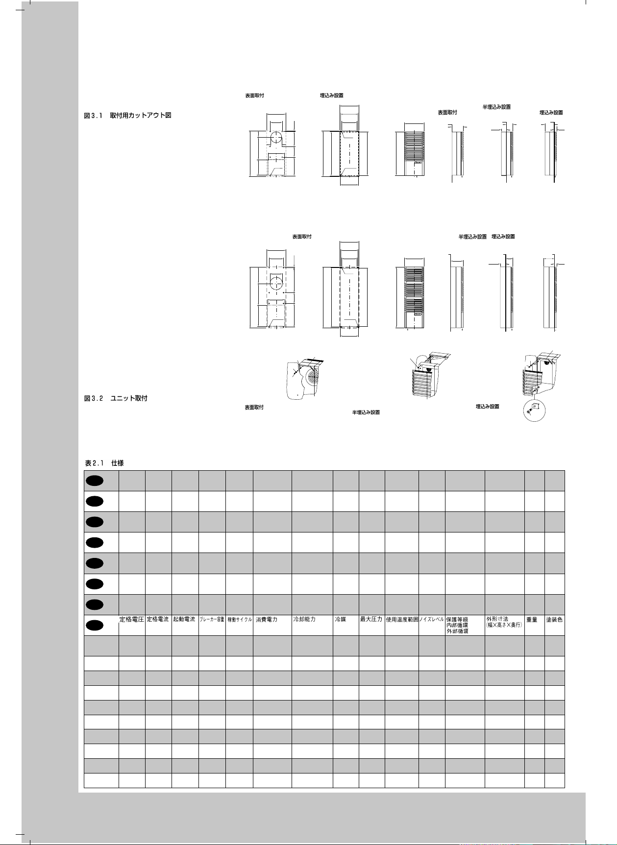
Abb. 3.1 Montageausschnitte
Fig. 3.1 Mounting Cut-out
Fig. 3.1 Découpe de montage
Afb. 3.1 Montage-uitsparingen
Bild 3.1 Håltagning
Fig. 3.1 Dime di foratura
Fig. 3.1 Recorte del montaje
SK 3298.... / 3279.100 / 3260.500
Abb. 3.2 Gerätemontage
Fig. 3.2 Mounting
Fig. 3.2 Montage de l’appareil
Afb. 3.2 Apparaatmontage
Bild 3.2 Aggregatmontage
Fig. 3.2 Montaggio dell’apparecchio
Fig. 3.2 Montaje del aparato
Tab. 2.1 T ec hnisc he Daten
Tab. 2.1 T ec hnical Data
Tab. 2.1 Données techniques
Tab. 2.1 T ec hnisc he gegevens
Tab. 2.1 T ekniska data
Tab. 2.1 Caratteristiche tecniche
Tab. 2.1 Datos técnicos
Betriebs-
Nenn-
Anlauf-
D
GB
F
NL
S
I
E
J
SK 3293.100
SK 3293.500
SK 3293.140
SK 3293.540
SK 3281.100
SK 3393.100
SK 3393.500
SK 3393.140
SK 3393.540
SK 3381.100
SK 3298.100
SK 3298.500
SK 3279.100
SK 3260.500
SK 3260.140
spannung
Operating
voltage
Tension
nominale
Bedrijfs-
spanning
Anslut-
ningsspänning
Tensione
nominale
Tensión
de
servicio
230 V,
50/60 Hz
400 V,
50/60 Hz
115 V,
50/60 Hz
230 V,
50/60 Hz
400 V,
50/60 Hz
115 V,
50/60 Hz
230 V,
50/60 Hz
115 V,
50/60 Hz
400 V– 3~
50/60 Hz
strom
Rated
current
Courant
nominal
Nominale
stroom
Märk-
ström
Corrente
nominale
Intensidad
nominal
3.1 A/
3.6 A
1.8 A/
2.1 A
6.5 A/
7.6 A
4.2 A/
4.4 A
2.5 A/
2.6 A
8.6 A/
9.2 A
5.5 A/
5.7 A
11.5 A/
12.0 A
2.3 A/
2.6 A
Vorsiche-
strom
rung T
Starting
Pre-fuse TDuty cycle Power
current
Courant de
Dispositif
démarrage
de sécurité
T
Aanloop-
Primaire
stroom
zekering T
Startström Försäkring gLInkopp-
Corrente
Fusibili T Ciclo d’in-
di spunto
Intensidad
Fusible T Duración
de
arranque
8.5 A/
6 A/
10.0 A
6 A
4.6 A/
4 A/
5.8 A
4 A
16.4 A/
10 A/
20.1 A
10 A
9.8 A/
6 A/
11.4 A
6 A
5.7 A/
6 A/
6.6 A
6 A
19.8 A/
10 A/
23.1 A
10 A
17.5 A/
10 A/
16.5 A
10 A
36.0 A/
16 A/
37.0 A
16 A
9.5 A/
6 A/
9.5 A
6 A
Anbau Einbau
External Installation Internal Installation
Implanté Intégré
Aanbouw Inbouw
Utanpå Inbyggnad
Montaggio sporgente Montaggio incassato
Montaje exterior Montaje interior
920
950
1265
1235
Refrigerant Permis-
Fluide
frigorigène
Koelmiddel
Kylmedel Tillåtet
Fluido
frigorigeno
Fluido
frigorífico
R134 a,
525 g
R134 a,
525 g
R134 a,
525 g
R134 a,
550 g
R134 a,
550 g
R134 a,
550 g
R134 a,
525 g
R134 a,
525 g
R134 a,
525 g
400
360
320
Ø 7
(4 x)
900
Ø 9.5
(4 x)
380
400
360
320
Ø 7
(4 x)
1215
Ø 9.5
(4 x)
380
Teileinbau
Partially Internal
Installation
Partiellement
intégré
Gedeeltelijke
inbouw
Delvis inbyggnad
Montaggio
semincassato
Montaje parcial
Betriebsüberdruck
sible
pressure
Pression
de régime
autor.
p. max. Temperatuur-
driftsövertryck
Pressione
max.
Presión
máxima
admis.
25 bar
25 bar
25 bar
24 bar
24 bar
24 bar
25 bar
25 bar
24 bar
950
1265
M 8
SW 13
Temperaturbereich
Temperature
range
Plage de
température
bereik
Temperatur-
område
Campo di
temperatura
Campo de
temperaturas
+ 20 –
+ 55°C
+ 20 –
+ 55°C
+ 20 –
+ 55°C
+ 20 –
+ 55°C
+ 20 –
+ 55°C
+ 20 –
+ 55°C
+ 20 –
+ 55°C
+ 20 –
+ 55°C
+ 20 –
+ 55°C
400
A
15
135
465
950
320
345
450440
1265
Anbau
External
Installation
Implanté
Aanbouw
Utanpå
Montaggio
sporgente
Montaje
exterior
* Nur für 400 mm tiefe PS/ES Schränke SK 3393.... / 338.1100, A = 250 mm, B = 300 mm
Nur für Schränke über 400 mm Tiefe SK 3393.... / 338.1100 A = 250 mm, B = 340 mm
Nur für Schränke über 400 mm Tiefe SK 3293.... / 328.1100 A = 300 mm, B = 340 mm
Einschalt-
Nennleistung Nutzkühlleistung Kältemittel zul.
dauer
consumption
Durée de
Puissance
mise en
nominale
circuit
Inschakel-
Nominaal
duur
vermogen
Märkeffekt Effektiv
lingstid
Potenza
serzione
nominale
Potencia
de
nominal
conexión
L35 L35
L35 L50
450 W/500 W
100 %
500 W/580 W
470 W/520 W
100 %
520 W/605 W
470 W/520 W
100 %
520 W/605 W
590 W/660 W
100 %
670 W/750 W
610 W/680 W
100 %
690 W/780 W
610 W/680 W
100 %
690 W/780 W
830W/1040W
100 %
940W/1170W
860W/1080 W
100 %
975W/1210W
900W/750W
100 %
1060W/920W
310225385
230
B
Ø 9.5
(4 x)
Anbau
External Installation
Implanté
Aanbouw
Utanpå
Montaggio sporgente
Montaje exterior
400
300
15520225490
260
360
Ø 9.5
(8 x)
A 8.4
M 8
SW 13
Useful cooling
output
Puissance
frigorifique
de rég.
Nuttig
koelvermogen
10 x 8
M 8 x 30
kyleffekt
Potenza
frigorifera utile
Potencia
frigorífica útil
DIN 3168/EN 814
L35 L35
L35 L50
825 W/960 W
680 W/720 W
825 W/960 W
680 W/720 W
825 W/960 W
680 W/720 W
1100W/1150 W
830W/850W
1100W/1150W
830W/850W
1100W/1150W
830W/850W
1400W/1450W
1100W/1150W
1400W/1450W
1100W/1150W
1740W/1630W
1340W/1220W
Anbau
External
Installation
Implanté
Aanbouw
Utanpå
Montaggio
sporgente
Montaje
exterior
400
Internal or Partially Internal Installation
Montaggio semincassato o incassato
400
Geräuschpegel
Noise
level
Niveau
sonore
Geluidsnivo
Ljudnivå Kapslingsklass
Livello
di rumore
Nivel
de ruido
62 dB (A)
62 dB (A)
62 dB (A)
62 dB (A)
62 dB (A)
62 dB (A)
62 dB (A)
62 dB (A)
65 dB (A)
Teileinbau
Partially
Installation
Partiellement Intégré
Gedeeltelijke inbouw
Delvis inbyggnad
Montaggio
semincass.
Montaje parcial
230
Teileinbau, Einbau
Partiellement intégré, intégré
Delvis inbyggnad, inbyggnad
Montaje parcial, montaje interior
260
Einbau
Internal
Installation
Intégré
Inbouw
Inbyggnad
Montaggio
incassato
Montaje
interior
Schutzart
Innenkreislauf
Außenkreislauf
Protection categ.
Internal circuit
External circuit
Degré de protect.
Circuit intérieur
Circuit extérieur
Beschermklasse
Inwendig circuit
Uitwend. circuit
Inre kretslopp
Yttre kretslopp
Grado di protez.
Circuito interno
Circuito esterno
Protección
Circuito interior
Circuito exterior
100
Inbouw
,
100
Abmessungen
(B x H x T)
mm
Dimensions
(W x H x D)
mm
Dimensions
(L x H x P)
mm
Afmetingen
(B x H x D)
mm
Mått
(B x H x D)
mm
Dimensioni
(L x A x P)
mm
Dimensiones
(anch. x alt.
x prof.) mm
130
160
M 6
SW 13
EN 60 529
IP 54
IP 34
IP 54
IP 34
IP 54
IP 34
IP 54
IP 34
IP 54
IP 34
IP 54
IP 34
IP 54
IP 34
IP 54
IP 34
IP 54
IP 34
400 x 950 x 230 35 kg
400 x 950 x 230 38 kg
400 x 950 x 230 38 kg
400 x 950 x 230 38 kg
400 x 950 x 230 41 kg
400 x 950 x 230 41 kg
400 x 1265 x 260 48 kg
400 x 1265 x 260 51 kg
400 x 1265 x 260 60 kg
Einbau
Internal
Installation
Intégre
Inbouw
Inbyggnad
Montaggio
incassato
Montaje
interior
185
215
A 8.4
B 4.8 x 13
Gewicht Farbton
Weight Colour
Poids Coloris
Gewicht Kleur
Vikt Färgton
Peso Colore
Peso Color
RAL
7032
RAL
7032
RAL
7032
RAL
7032
RAL
7032
RAL
7032
RAL
7032
RAL
7032
RAL
7032
45
45
10 x 4
English
Contents
1. Application
2. Technical data
3. Assembly
4. Electrical connection
5. Commencing operation and control
behaviour
6. BUS System (Model No. SK 3124.000)
7. Technical information
8. Maintenance
9. Scope of supply and guarantee
10. Fault indication and fault analysis
11. Programming
1. Application
Enclosure cooling units are designed and built
to dissipate heat from enclosures, by cooling
the air inside the enclosure and protecting temperature sensitive components. Enclosure cooling units are particularly suitable for the
temperature range of + 40 ° C to + 55 ° C.
2.Technical Data
(see table 2.1)
3. Assembly
The cooling unit can be mounted either internally, partially internally or externally.
Make cutouts and drill holes at the mounting
position (see fig. 3.1). Cut the enclosed seal to
the required length and attach it to the unit (see
fig. 3.2). In the case of external mounting screw
set-screws M8 x 30 into the blind nuts at the
rear face of the unit and fix them by means of
washers A 8.4 and nuts M8. In the case of partially internal mounting the unit has to be divided
by removing the lamella grille and unscrewing
the nuts M8. For external, partially internal and
internal mounting see fig. 3.2.
Prior to mounting, ensure that:
v
the site for the enclosure, and hence the
arrangement of the cooling unit, is selected
so as to ensure good ventilation;
v
the location is free from excessive dirt and
moisture;
v
the round cut-out for air extraction is located
in the upper area of the enclosure;
v
the mains connection ratings, as stated on
the name plate, are available;
v
the ambient temperature is no higher than
+55 ° C;
v
the packaging shows no signs of damage;
v
the enclosure is sealed on all sides.
Condensation will occur if the enclosure is
leaky;
v
the separation of the units from one another
and from the wall should not be less than
200 mm;
v
air inlet and outlet are not obstructed on the
inside of the enclosure;
v
units are only fitted vertically in the specified
position. Max. deviation from true vertical: 2 ° ;
v
condensate discharge must be made up by
means of the material provided in the dispatch bag. The discharge tube must be free
from kinks and must be arranged sloping
away from the unit;
v
electrical connection and repair are carried
out only by authorized specialist personnel.
Use only original replacement parts!
v
To avoid an increase in condensation, a door
operated switch (e.g. PS 4127.000) should
be used which will switch the cooling unit off
when the enclosure door is opened (see
5.2.3.3).
4.Electrical Connection
The connected voltage and frequency must correspond to the values stated on the name plate. The
cooling unit must be connected to the mains via
an isolating device, which ensures at least 3 mm
contact opening when switched off. The unit must
not have any additional temperature control connected before it. Line protection should be provided by means of the pre-fuse specified on the
name plate. Observe the relevant regulations
during installation!
Connect the mains connection to the plug-in terminal strip X10, see page 35.
Version .....500 / .540
Door limit switch, see 5.2.3.3
v
Collective fault signal connection, see 5.2.3.1
v
Note the designations on the terminal strip (see
wiring diagram).
v
The unit must be disconnected prior to
checking the protective earth conductor, high
voltage and the insulation in the enclosure.
5. Commencing Operation
and Control Behaviour
Following the completion of mounting and a
waiting period of approximately 30 minutes (to
allow oil to collect in the compressor in order to
ensure lubrication and cooling) electrical connection can be made.
5.1 Control by Thermostat
Version .....100 / .140
The cooling unit operates automatically, i.e. following the electrical connection, the evaporator fan
will run continuously to circulate the air inside the
enclosure. This provides a uniform temperature
distribution in the enclosure. The built-in temperature controller (setting the desired internal temperature) effects automatically controlled switch-off
of the cooling unit by the value of the fixed
switching difference setting of 5 K. This is set at
the factory to + 35 ° C.
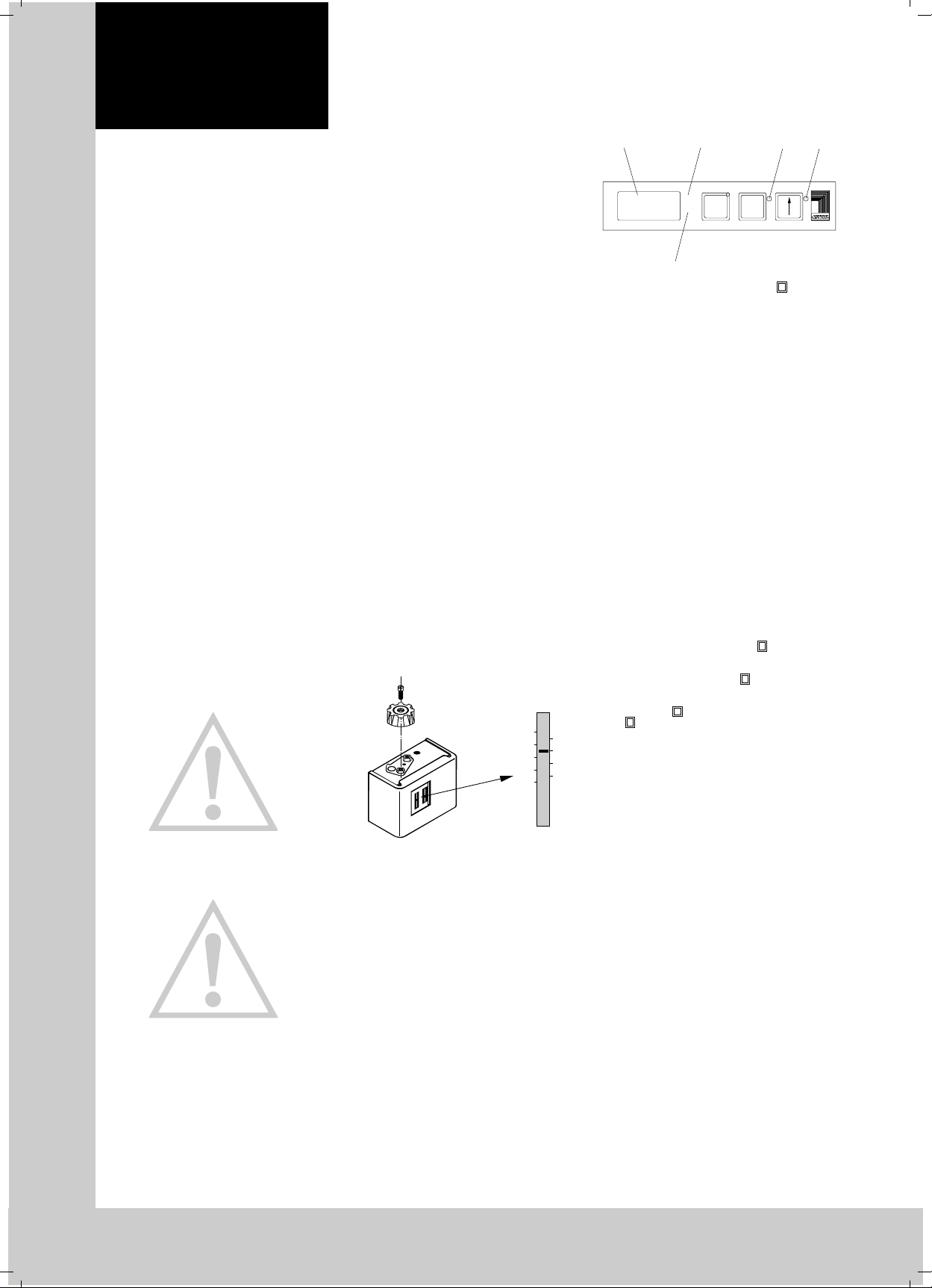
5.1.1 Temperature Setting at the Controller
Fig.5.1 Thermostat
20
25
30
35
40
45
50
55
60
°C °C
1. Remove the setting knob after slackening the
screw.
2. Remove locking plate.
3. Replace the setting knob and set the desired
temperature. Setting range + 20 ° C to + 55 ° C.
4. Replace the locking plate and fix the setting
knob by tightening the screw.
5.2 Control by Microcontroller
Version .....500 / .540
Fig. 5.2 Microcontroller
H2H1
°C
°F
H3
After electrical connection the internal fan turns on
and circulates the enclosure air. This helps assure
even temperature distribution within the enclosure.
The condensor fan and compressor are controlled
by the microcontroller. The minimum run time is
90 seconds. The switching difference is 5 – 10 K
and is set at the factory. In order to maximize
energy efficiency the thermostat should be set to
the highest enclosure temperature as allowed by
the electronics.
5.2.1 Operation of the Microcontroller
The display terminal H1 consists of a 3 position
7-segment display which indicates the enclosure
internal temperature in ° C or ° F (changeable, see
section 5.2.2) as well as any fault codes. The
actual enclosure internal temperature is constantly displayed. If a fault occurs then the fault
number is indicated in the left position. When programming the microcontroller the program level
and parameter value is indicated on the display.
When the “TEST” button is pushed the compressor and the fans will run for 5 minutes regardless
of the internal temperature or door limit switch.
This allows for a system test after an extended
shutdown period (e.g. after the winter).
5.2.2 Programming
(see diagram 5.1 page 39)
In the EEPROM of the microcontroller various
parameters are stored which can be changed
through using the “ENTER” and “ ” buttons,
9 different parameters are changeable as outlined
in table 5.1. To access the programming mode
push both the “ENTER” and “ ” buttons simultaneously for 10 seconds. The left digit will then
indicate the program level and the LED for the
“ENTER” and “ ” buttons will blink. By pushing
°C
the “ ” button the program level can be advan-
➡
ced to the next level. In order to access levels
10
5 through 9 a security code must be entered. If no
8
buttons are pushed for 60 seconds the display will
6
return to the standard mode which displays the
4
enclosure temperature. Programming of the para-
3
meters is made easy with diagram 5.1 on page
39. A description of the parameters to be pro-
grammed can be found in table 5.1. All parameters are stored in the EEPROM and are retained
when power is shut off to the air conditioner.
➡
ENTER
TEST
H1 = Display Terminal
H2 = LED °C
H3 = LED °F
H4 = LED ENTER
H5 = LED
➡
H5
H4
➡
➡
6
 Loading...