

Rittal SK 3296100, SK 3296500, SK 3272100, SK 3290100, SK 3290500 Assembly Instructions Manual
...
1. Application
Enclosure cooling units are designed and built to dissipate heat from enclosures, by cooling the air
inside the enclosure and protecting temperature sensitive components. Enclosure cooling units are
particularly suitable for the temperature range of +40ºC to +55ºC.
2. Technical Data :
Operating voltage
Rated current
Starting current
Pre-fuse T
Duty cycle
Nom. refrigeration
L35 L35
L35 L50
Useful cooling
output
DIN 3168/
EN 814
L35 L35
L35 L50
Refrigerant
Permissible
pressure
Temperature range
Noise level
Protection category
EN 60529
Internal circuit
External circuit
Dimensions
(WxHxD) mm
Weight
Color
SK 3296100
SK 3296500
230 V
50/60 Hz
3.2 A/3.9 A 6.3 A/6.6 A 5.3 A/6.0 A 10.5 A/12.8 A
11.4 A/11.0 A 18.2 A/20.7 A 16.6 A/15.5 A 24.6 A/28.7 A
6 A/6 A 10 A/10 A 6 A/10 A 16 A/16 A
100% 100% 100% 100%
330 W/430 W
390 W/525 W
800 W/860 W
615 W/685 W
R134 a, 750 g R134 a, 750 g R134 a, 780 g R134 a, 780 g
23 bar 23 bar 23 bar 23 bar
+20º C to +55ºC +20º C to +55ºC +20º C to +55ºC +20º C to +55ºC
62 dB (A) 62 dB (A) 62 dB (A) 62 dB (A)
IP 54
IP 34
600x340x464 600x340x464 600x400x426 600x400x426
38 kg 41 kg 44 kg 50 kg
RAL 7032 RAL 7032 RAL 7032 RAL 7032
SK 3272100 SK 3290100
SK 3290500
115 V
50/60 Hz
405 W/535 W
475 W/620 W
800 W/860 W
615 W/685 W
IP 54
IP 34
230 V
50/60 Hz
710 W/800 W
840 W/920 W
1450 W/1590 W
1060 W/1220 W
IP 54
IP 34
SK 3280100
115 V
50/60 Hz
740 W/825 W
860 W/940 W
1450 W/1590 W
1060 W/1220 W
IP 54
IP 34

3. Assembly
Make 2 cut-outs and screw holes in the top of the enclosure in accordance with fig. 3.1.
Prior to mounting, ensure that:
• the site for the enclosure, and hence the arrangement of the cooling unit, is selected so as to
• the location is free from excessive dirt and moisture;
• the mains connection ratings, as stated on the name plate, are available;
• the ambient temperature is no higher than +55ºC;
• the packaging shows no signs of damage. Traces of oil are an indication of coolant loss and
• the enclosure is sealed on all sides. Condensation will occur if the enclosure is leaky;
• the separation of the units from one another and from the wall should not be less than 200
• air inlet and outlet must not be obstructed on the inside;
• units should only be fitted vertically in the specified position. Max. deviation from true
ensure good ventilation;
of leakage in the unit system. Any damage to the packaging can become the cause of a
subsequent function failure;
mm;
vertical: 2º;
• condensate drainage is provided (see 6.3);
• electrical connection and repair must be carried out only by authorized specialist
personnel. Use only original replacement parts!
• To avoid an increase in condensation, a door operated switch (e.g. PS 4127) should be used
which will switch the cooling unit off when the enclosure door is opened (see 5.2.3.3).
Stick the enclosed sealing gasket onto the enclosure roof.
Important: To achieve a permanent seal between the cooling and the enclosure, the mounting
surface may have to be strengthened or supported (see example on PS 4206, fig. 3.2).
Accessories for roof plate stiffening on the PS:
Mounting rail
"U" nut
Fixing bracket
Threaded block
Screw 6 setscrews into the blind nuts on the underside of the unit and fix the unit with 6 washers
A6.4 and 6 nuts M6 underneath. For transportation of unit by crane: remove the blanking plug and
screw in an eyebolt M12.
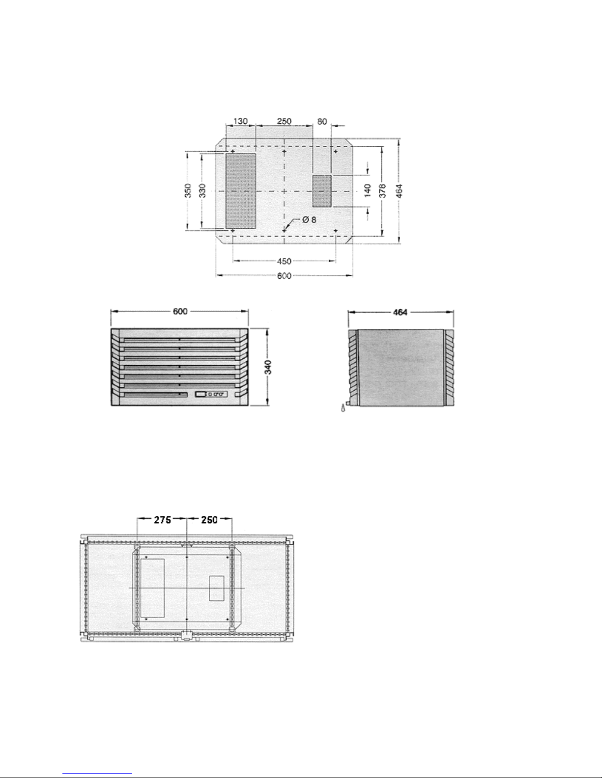
Figure 3.1 Mounting Cut-out SK 3296...3272100
Figure 3.2 Roof plate stiffening
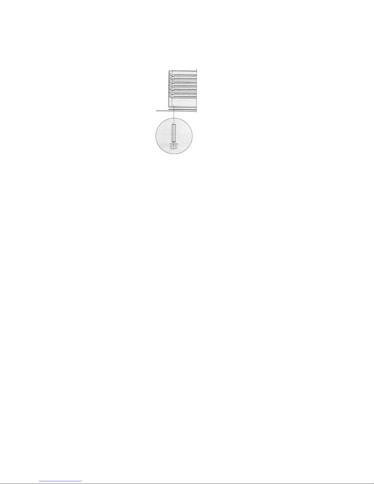
Figure 3.3 Mounting
4. Electrical Connection
The connected voltage and frequency must correspond to the values stated on the name plate. The
cooling unit must be connected to the mains via an isolating device, which ensures at least 3 mm
contact opening when switched off. The unit must not have any additional temperature control
connected before it. Line protection should be provided by means of the pre-fuse specified on the
name plate. Observe the relevant regulations during installation!
Version....100
Connection should be made to the cable attached to the unit (see Detailed Wiring Diagram).
Version....500
Connect the mains connection to the plug-in terminal strip X10 (see Wiring Diagram).
--Door limit switch, see 5.2.3.3
--Collective fault signal connection, see 5.2.3.1
--Note the designations on the terminal strip (see wiring diagram)
--The unit must be disconnected prior to checking the protective earth conductor, high voltage and
the insulation in the enclosure.
5. Commencing Operation and Control Behavior
Following the completion of mounting and a waiting period of approximately 30 minutes (to allow oil
to collect in the compressor in order to ensure lubrication and cooling) electrical connection can be
made.
5.1 Control by Thermostat
Version....100
The cooling unit operates automatically, i.e. following the electrical connection, the evaporator fan will
run continuously to circulate the air inside the enclosure. This provides a uniform temperature
distribution in the enclosure. The built-in temperature controller (setting the desired internal
temperature) effects automatically controlled switch-off of the cooling unit by the value of the fixed
switching difference setting of 5 K. This is set at the factory to +35ºC.
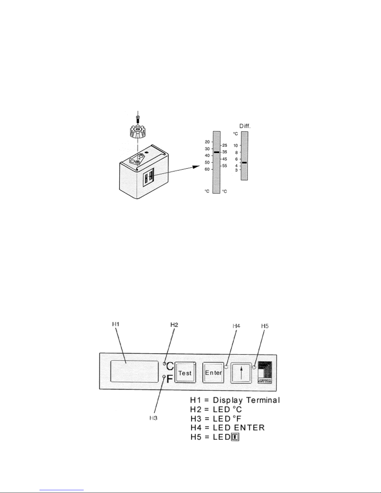
5.1.1 Temperature Setting at the Controller
Set the desired temperature. Setting range +20ºC to +55ºC.
To avoid cyclic operation of the compressor, it is imperative that the set switching difference of 5 K is
not changed and does not deviate to a lower value.
5.2 Control by Microcontroller
Version....500
After electrical connection the internal fan turns on and circulates the enclosure air. This helps
assure even temperature distribution within the enclosure. The condenser fan and compressor are
controlled by the microcontroller. The minimum run time is 90 seconds. The switching difference is
5-10 K and is set at the factory. In order to maximize energy efficiency the thermostat should be set
to the highest enclosure temperature as allowed by the electronics.
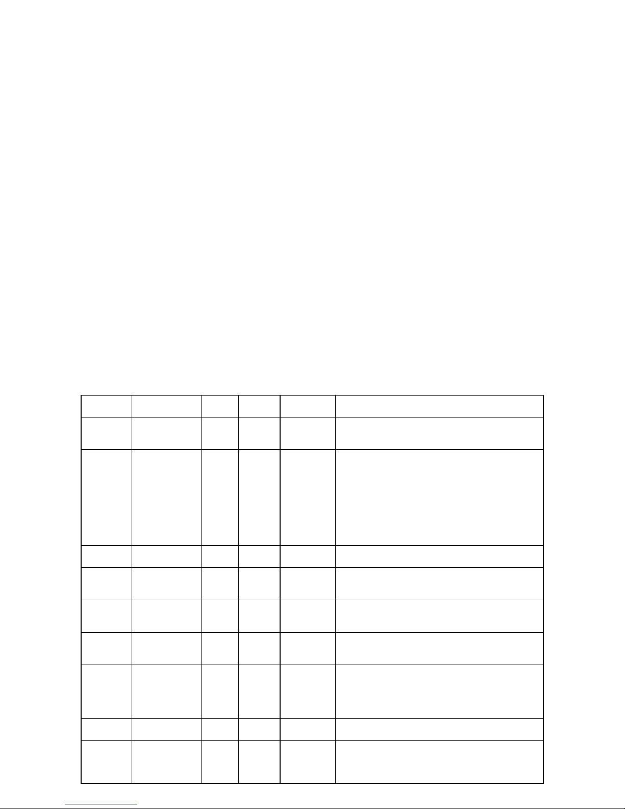
5.2.1 Operation of the Microcontroller
The display terminal H1 consists of a 3 position 7-segment display which indicates the enclosure
internal temperature in ºC or ºF (changeable, see section 5.2.2) as well as any fault codes. The
actual enclosure internal temperature is constantly displayed. If a fault occurs then the fault number
is indicated in the left position. When programming the microcontroller the program level and
parameter value is indicated on the display.
When the "TEST" button is pushed the compressor and the fans will run for 5 minutes regardless of
the internal temperature or door limit switch. This allows for a system test after an extended
shutdown period (e.g. after the winter).
5.2.2 Programming
In the EEPROM of the microcontroller various parameters are stored which can be changes through
using the "ENTER" and buttons, 9 different parameters are changeable as outlined in table
5.1. To access the programming mode push both the "ENTER" and buttons simultaneously for 10
seconds. The left digit will then indicate the program level and the LED for the "ENTER"
and buttons will blink. By pushing the button the program level can be advanced to the next
level. In order to access levels 5 through 9 a security code must be entered. If no buttons are
pushed for 60 seconds the display will return to the standard mode which displays the enclosure
temperature. Programming of the parameters is made easy with diagram 5.1 on page 35. A
description of the parameters to be programmed can be found in table 5.1. All parameters are stored
in the EEPROM and are retained when power is shut off to the air conditioner.
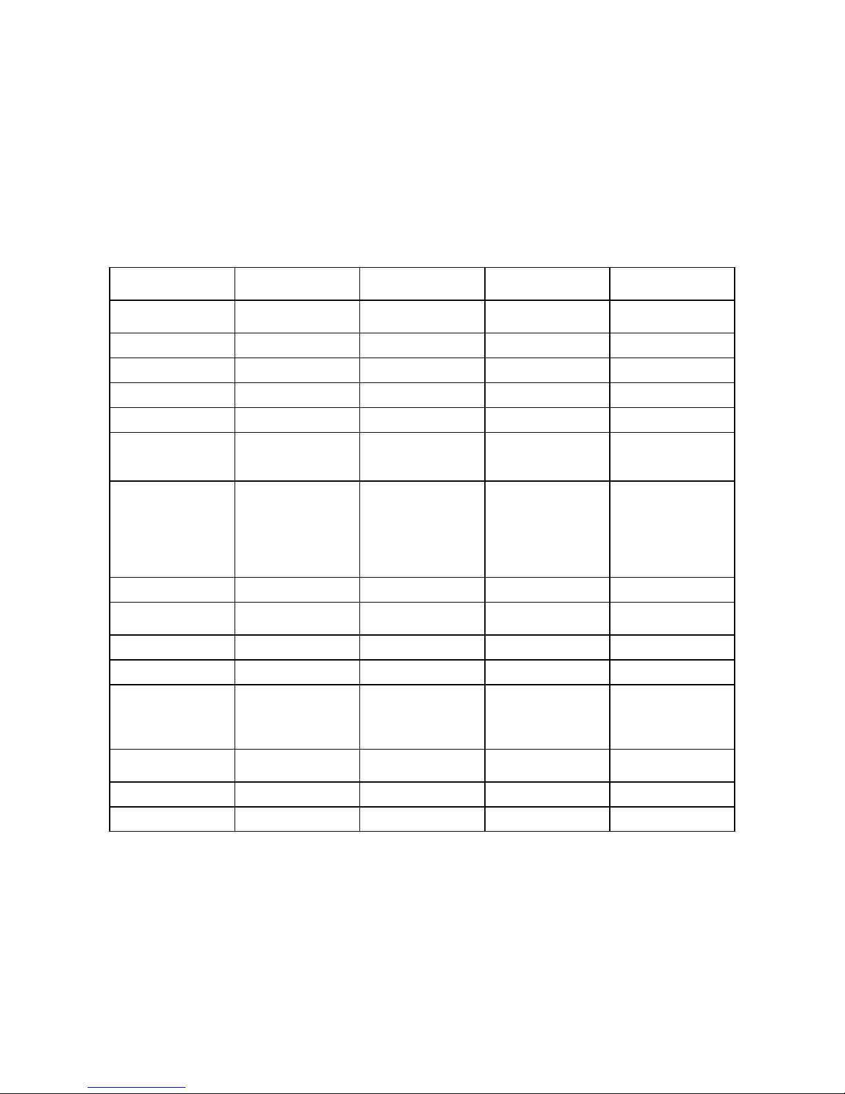
Table 5.1
Program
Level
1
2
3
4 Security code
5
6
7
8
9
Changeable
Parameter
Internal
enclosure
temperature T
Set value of filter
mat monitor
Imperial/metric
units ºC/ºF
Minimum
thermostat
setting
Maximum
thermostat
setting
Alarm setting for
enclosure
temperature
Setting of PLC
interface
Turn off of
evaporator fan
Min.
Value
30 45 35
i
4
0 1 0
20 35 30
40 55 45
3 15 5
0 1 0
0 1 0
Max.
Value
40
(99=off)
Factory
Setting
99
123
Description
The standard thermostat setting range is 3545ºC. The upper and lower limits can be adjusted
through program level 5 and 6.
Factory setting is the shut off value (99). To
activate:
1. Install clean filter mat and let air conditioner cool
for a few minutes.
2. Select program level 2.
3. Push test button 10 seconds. Temperature
difference is displayed.
4. Using the button adjust the temperature 2-3 K
above the displayed value.
The enclosure temperature can be displayed in
both ºC and ºF.
In order to access program level 5-9 the code
"123" must first be entered through program level
4.
The minimum thermostat setting can be adjusted
from 35ºC to 20ºC.
The maximum thermostat setting can be adjusted
from 40ºC to 55ºC.
Due to the standard factory setting of 5 K the fault
code 1 is displayed when the enclosure
temperature is 5 K or more above the thermostat
setting. This "alarm temperature" setting can be
adjusted from 3 to 15ºC.
The factory setting is for serial interface. Parallel
interface is activated by selecting 1.
With the factory setting the evaporator fan turns off
for 1 minutes each time the unit cycles. This helps
condensate drainage. This feature can be turned
off by changing the setting to 1.
 Loading...