

Rittal SK 3269.100, SK 3269.140, SK 3265.100, SK 3262.100, SK 3266.100 Assembly Instructions Manual
Umschalten auf PerfektionUmschalten auf Perfektion
Umweltorientierte
Kühltechnik
SK 3269.100
SK 3269.140
SK 3265.100
SK 3262.100
SK 3266.100
Montageanleitung
Assembly instructions
Notice de montage
Montage-instructie
Montageanvisning
Istruzioni di montaggio
Instrucciones de montaje
348
340
600
525
305
Ø 8
145
26
160
77
208
540
340
120
600
400
M6
SW 10
A 6.4
M6 x 40
10 x 4
M6
SW 10
A 6.4
Cover
Housing
Sealing
gasket
15 x 5*
210
605 ± 1
74
400
32
635
Ø 8
64
34
Ø 8
635
400
378
360 ± 1
605 ± 1
577
16
44
194
52
15
50
23
124
635
400
248
205
45
4
Contents
1. Application
2. Technical data
3. Assembly
4. Electrical connection
5. Commencing operation and control behaviour
6. Technical information
7. Maintenance
8. Scope of supply and guarantee
9. Spares list
1. Application
Enclosure cooling units are designed and built
to dissipate heat from enclosures by cooling the
air inside the enclosure and protecting
temperature sensitive components.
Enclosure cooling units are particularly suitable
for the temperature range of + 20 ° C to + 55 ° C.
2.Technical data
(see table 2.1).
3. Assembly
Prior to mounting, ensure that:
v
the site for the enclosure, and hence the
arrangement of the cooling unit, is selected
so as to ensure good ventilation;
v
the location is free from excessive dirt and
moisture;
v
the mains connection ratings, as stated on
the data plate, are available;
v
the ambient temperature is no higher than
+55 ° C (50 ° C SK 3269.... / SK 3262.100);
v
the packaging shows no signs of damage.
Traces of oil are an indication of coolant loss
and of leakage in the unit system. Any
damage to the packaging can become the
cause of a subsequent function failure;
v
the enclosure is sealed on all sides.
Condensation will occur if the enclosure is
leaky;
v
the separation of the units from one another
and from the wall should not be less than
200 mm;
v
air inlet and outlet are not obstructed on the
inside;
v
units should only be fitted vertically in the
specified position. Max. deviation from true
vertical: 2
o
(see 6.3);
v
condensate discharge hose has to be fitted;
v
electrical connection and repair must be
carried out only by authorized specialist
personnel. Use only original replacement
parts!
v
to avoid an increase in condensation, a door
operated switch (e.g. PS 4127.000) should
be used which will switch the cooling unit off
when the enclosure door is opened.
4.Electrical connection
The connected voltage and frequency must
correspond to the values stated on the data
plate. The cooling unit must be connected to the
mains via an isolating device, which ensures at
least 3 mm contact opening when switched off,
The unit must not have any additional
temperature control connected before it. Line
protection should be provided by means of the
pre-fuse specified on the data plate. Observe the
relevant regulations during installation!
Connection should be made to the cable
attached to the unit.
(See detailed wiring diagram page 18).
5. Commencing operation
and control behaviour
Following the completion of mounting and a
waiting period of approximately 30 minutes (to
allow oil to collect in the compressor), electrical
connection can be made in order to ensure
lubrication and cooling.
English
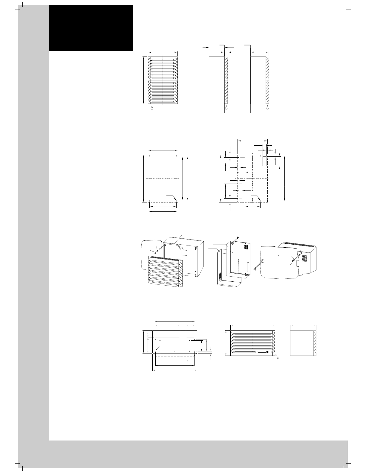
Fig. 3.2 Mounting cutout SK 3269.... / SK 3262.100
Make cutouts and drill holes at the mounting position (see fig. 3.2).
Fig. 3.4 Mounting cutout SK 3265.100 / SK 3266.100
Fig. 3.1 Assembly SK 3269.... / SK 3262.100
Internal installation
External installation
Internal installation External installation
Fig. 3.3 Assembly SK 3269.... / SK 3262.100
Internal installation External installationInternal installation
* Attach the sealing gasket 15 x 5 mm, ident. no. 209631, neatly to the edges as shown in the drawing
and make a straight, right-angled cut to length!
Horizontal and vertical sides must be cut to length from two pieces and not formed from just one!
Make 2 cutouts and 4 screw holes in the top of the enclosure in accordance with fig. 3.4.
Stick the enclosed sealing gasket onto the enclosure roof.
5.1 Control behaviour
The cooling unit operates automatically, i.e.
following the electrical connection, the evaporator fan will run continuously to circulate the air
inside the enclosure. This provides a uniform
temperature distribution in the enclosure. The
built-in temperature controller (setting the desired
internal temperature) effects automatically
controlled switch-off of the cooling unit by the
value of the fixed switching difference setting of
5 K. This is set at the factory to + 35 ° C.
5
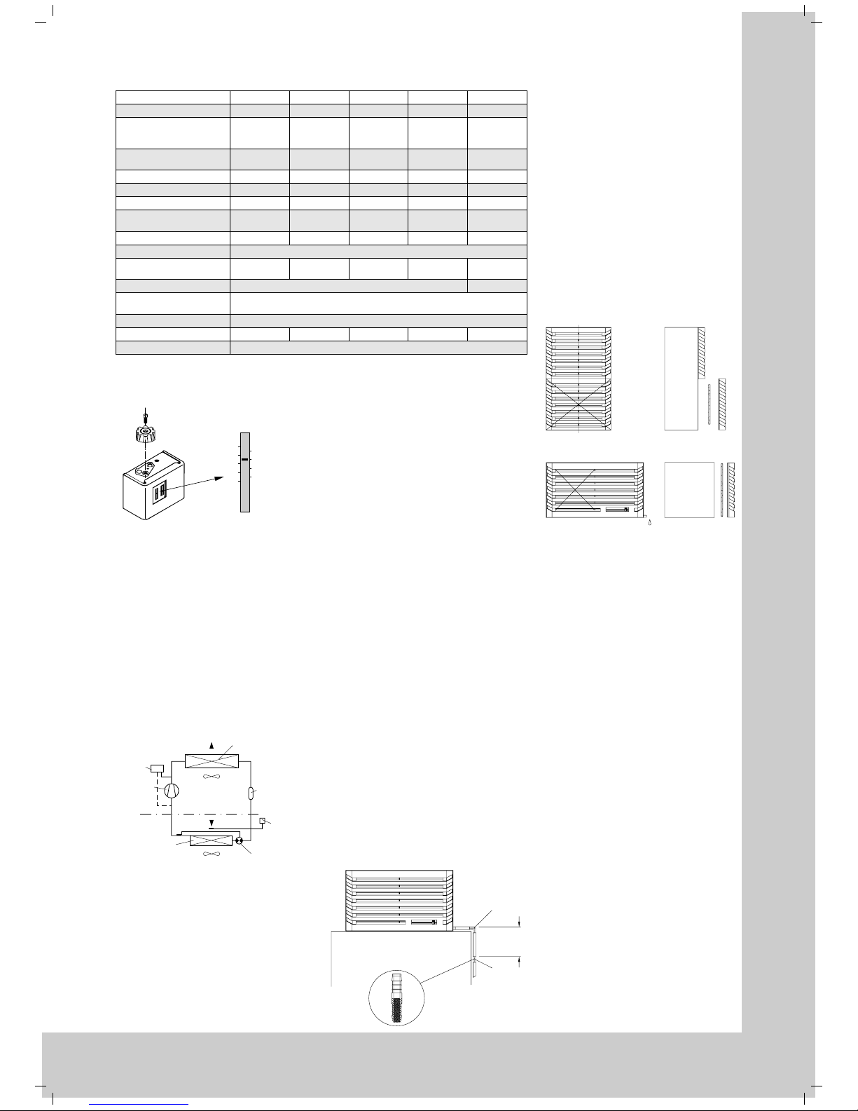
Tab. 2.1 Technical data
Model No. SK 3269.100 3269.140 3265.100 3262.100 3266.100
Operating voltage V/Hz 230/50/60 400/50/60 230/50/60 115/50/60 115/50/60
Dimensions mm W
(W x H x D) H
D
400
635
248
400
635
248
600
340
348
400
635
248
600
340
348
Useful cooling L35 L35
output DIN 3168 L35 L50
680 W/700 W
500 W/520 W
680 W/700 W
500 W/520 W
410 W/380 W
230 W/240 W
680 W/700 W
500 W/520 W
410 W/380 W
230 W/220 W
Rated current max. 3.1 A/ 4.0 A 1.8 A/2.3 A 2.2 A/2.5 A 5.1 A/ 6.0 A 4.5 A/ 5.2 A
Starting current 12.6 A/14.4 A 7.2 A/8.3 A 6.6 A/7.2 A 25.2 A/34.3 A 13.5 A/13.5 A
Pre-fuse T 6.0 A/ 6.0 A 4.0 A/4.0 A 6.0 A/6.0 A 6.0 A/10.0 A 6.0 A/ 6.0 A
Nominal power L35 L35
consumption L35 L50
460 W/580 W
520 W/660 W
480 W/600 W
540 W/675 W
310 W/440 W
350 W/450 W
480 W/600 W
540 W/675 W
325 W/450 W
365 W/490 W
Refrigerant R134a, 300 g R134 a, 300 g R134 a, 325 g R134a, 300 g R134 a, 325 g
p. max. 24 bar
Temperature range + 20 ° C
to + 50 ° C
+ 20 ° C
to + 50 ° C
+ 20 ° C
to + 55 ° C
+ 20 ° C
to + 50 ° C
+ 20 ° C
to + 55 ° C
Noise level 65 dB (A)
Protective category
EN 60 529/10.91
External circuit IP 34
Internal circuit IP 54
Duty cycle 100 %
Weight 32.5 kg 35 kg 26 kg 35 kg 29 kg
Colour RAL 7032
5.2 Temperature setting at the controller
Fig.4.1 Thermostat
Set the desired temperature.
Setting range + 20 ° C to + 55 ° C.
6.Technical information
The cooling unit (compression refrigeration unit)
consists of four main components: the coolant
compressor , evaporator, liquefier (condenser),
and the control or expansion valve, which are
connected by suitable pipework. This circuit is
filled with a readily boiling substance, the
coolant. The R134a (CH
2
FCF
3
) coolant is free
from chlorine. It has an ozone destroying potential
(ODP) of 0 and is therefore environmentally
friendly. A filter dryer which is integrated in the
hermetically sealed cooling circuit, provides
effective protection against moisture, acid, dirt
particles, and foreign bodies within the cooling
circuit.
6.1 Operation of the cooling unit
Fig. 6.1 Cooling circuit
When the coolant compressor is put into
operation, the coolant vapour evaporates from the
evaporator. The heat required for the evaporation
of the coolant is drawn from the evaporator
environment (internal circuit of the enclosure),
causing it to cool down. The heat fed to the
coolant in the evaporator is dissipated by the
liquefier to its environment (assisted by fans),
making the coolant once more liquid due to the
condensation which takes place. In the
thermostatically controlled expansion valve, the
liquid coolant is reduced to the particular
evaporator pressure required. The cooling which
occurs due to the reduction of pressure, releases
the heat from the liquid, which evaporates part of
the coolant flow. The mixture of cold liquid and
throttle vapour is returned to the evaporator.
20
30
°C °C
55
60
50
45
40
35
25
Fan 2
Fan 1
Pressostat
Compressor
Evaporator
External circuit
Internal circuit
Expansion valve
Thermostat
Filterdryer
Liquefier
The cooling cycle is thus completed, the
aforementioned process of the heat transfer starts
afresh.
6.2 Safety equipment
The cooling circuit of the cooling unit embodies
a component tested high/low pressure monitor to
VBG 20 § 7.1 which is set to maximum operating
pressure and operates via an automatic reset
device at recurring pressure drop. The coolant
compressor and the fans are equipped with
thermal winding protection against excess
current and excess temperature.
6.3 Condensate discharge
SK 3269.... / SK 3262.100:
Automatic condensate evaporation.
Condensate is discharged downwards.
Insert the discharge socket Ø 12 mm piece
into the unit aperture.
SK 3265.100 / SK 3266.100:
1. To drain away any incidental condensate,
attach a discharge hose to the 12 mm dia.
pipe connection piece, which protrudes from
the unit.
Connect the drain hose to the angled connection piece (1) (avoiding any kinks) and route
the hose directly downwards in order to
prevent any backflow and overflow of the
condensate inside the unit.
2. To prevent external air flowing through the
condensate discharge connection piece into
the interior of the enclosure, fit the enclosed
backflow preventer (2) in the drain hose.
The nonwoven fabric inserted in the backflow
preventer ensures safe drainage of the
condensate.
The backflow preventer may become contaminated over a period of time and should be
examined at least once per annum and
replaced as necessary.
6.4 General
Storage temperature: The cooling units must
not be subjected to temperatures above
+ 70 ° C during storage.
Transport attitude: The cooling units must
always be transported upright.
Waste disposal: The closed cooling circuit
contains coolant and oil which must be correctly
disposed of for the protection of the environment.
The disposal can be carried out at Rittal-Werk.
Fig. 6.2 Condensate discharge
2
1
min.
500 mm
7.Maintenance
As a maintenance-free, hermetically sealed
system, the cooling circuit has been filled in
the factory with the required amount of
coolant, and tested for leaks and subjected to
a function trial run. The installed maintenancefree fans use bull bearings, they are
protected against moisture and dust, and are
fitted with a temperature monitor. The life
expectancy is at least 30,000 operating
hours. The cooling unit is thus largely
maintenance-free.
All that may be required from time to time is
that the components of the external air circuit
are cleaned by compressed air. The use of a
filter mat is recommended only if large
particles of lint are present in the air, so that
blockage of the condenser is prevented.
(Filter mat replacement, fig. 7.1).
Caution: Prior to any maintenance work, the
cooling unit must be switched free from
potential on the supply side.
Fig. 7.1 Filter mat replacement
SK 3269.... / SK 3262.100
x = removable inlet grille
8.Scope of supply and
guarantee
1 cooling unit, ready for connection
4 setscrews M6 x 30
4 nuts M6
4 serrated washers A 6,4
1 sealing cover
1 sealing tape
1 angle (SK 3265.100 / SK 3266.100)
1 backflow preventer
(SK 3265.100 / SK 3266.100)
1 drilling template
1 set of mounting and operating instructions
Guarantee:
This unit is covered by a 1-year guarantee from
the date of supply, subject to correct usage.
Within this period, the returned unit will be
repaired in the factory or replaced free of
charge.
The cooling unit is to be used for the cooling of
enclosures only. If it is connected or handled
improperly the manufacturer’s guarantee does
not apply and in this case we are not liable for
any damage caused.
9.Spares list
(see page 19).
SK 3265.100 / SK 3266.100
 Loading...