

Rittal SK 3209. Series, SK 3210. Series Assembly And Operating Instructions Manual

R
SK 3209.xxx
SK 3210.xxx
Montage-, Installations- und Bedienungsanleitung
Assembly and operating instructions
Manuel d’installation et de maintenance
Montage- en bedieningshandleiding
Montage- och hanteringsanvisning
Istruzioni di montaggio e funzionamento
Instrucciones de montaje
Luft/WasserWärmetauscher
Air/water
heat exchangers
Echangeurs
thermiques air/eau
Lucht/waterwarmtewisselaars
Luft/vatten
värmeväxlare
Scambiatori di calore
aria/acqua
Intercambiadores
de calor aire/agua


Rittal air/water heat exchanger assembly instructions 3
EN
Contents
1 Notes on documentation. . . . . . . . . . 4
1.1 Associated documents . . . . . . . . . . . . . . . . 4
1.2 CE Labelling . . . . . . . . . . . . . . . . . . . . . . . . . 4
1.3 Retention of documents . . . . . . . . . . . . . . . 4
1.4 Symbols used. . . . . . . . . . . . . . . . . . . . . . . . 4
2 Safety notes . . . . . . . . . . . . . . . . . . . . 4
3 Device description . . . . . . . . . . . . . . . 5
3.1 Functional description. . . . . . . . . . . . . . . . . 5
3.1.1 How it works. . . . . . . . . . . . . . . . . . . . . . . . . . 5
3.1.2 Control . . . . . . . . . . . . . . . . . . . . . . . . . . . . . . 5
3.1.3 Bus mode (Comfort controller only). . . . . . . . 5
3.1.4 Safety equipment. . . . . . . . . . . . . . . . . . . . . . 6
3.1.5 Condensation. . . . . . . . . . . . . . . . . . . . . . . . . 6
3.1.6 Leak detection . . . . . . . . . . . . . . . . . . . . . . . . 6
3.1.7 Door limit switch. . . . . . . . . . . . . . . . . . . . . . . 6
3.1.8 Additional interface X3
(Comfort controller only) . . . . . . . . . . . . . . . . 6
3.2 Proper use . . . . . . . . . . . . . . . . . . . . . . . . . . 6
3.3 Scope of supply . . . . . . . . . . . . . . . . . . . . . . 7
4 Assembly and connection . . . . . . . . 7
4.1 Choosing the installation site . . . . . . . . . . . 7
4.2 Assembly instructions. . . . . . . . . . . . . . . . . 7
4.2.1 General . . . . . . . . . . . . . . . . . . . . . . . . . . . . . 7
4.2.2 Layout of the electronic components
in the enclosure . . . . . . . . . . . . . . . . . . . . . . . 8
4.3 Assembling air/water heat exchangers . . . 9
4.3.1 Cutting out the enclosure. . . . . . . . . . . . . . . . 9
4.3.2 Assembling air/water heat exchangers . . . . . 9
4.4 Connecting the condensate discharge . . 10
4.5 Connecting the water connection . . . . . . 10
4.5.1 Notes on water quality . . . . . . . . . . . . . . . . . 11
4.6 Notes on electrical installation . . . . . . . . . 11
4.6.1 Connection data . . . . . . . . . . . . . . . . . . . . . 11
4.6.2 Overvoltage protection
and supply line load . . . . . . . . . . . . . . . . . . 11
4.6.3 Door limit switch. . . . . . . . . . . . . . . . . . . . . . 12
4.6.4 Notes on the flicker standard. . . . . . . . . . . . 12
4.6.5 Potential equalisation. . . . . . . . . . . . . . . . . . 12
4.7 Carrying out the electrical installation. . . 13
4.7.1 Bus connection
(only when interconnecting several units
with a Comfort controller). . . . . . . . . . . . . . . 13
4.7.2 Installing the power supply . . . . . . . . . . . . . 15
4.8 Finalising assembly . . . . . . . . . . . . . . . . . . 17
4.8.1 Finalising air/water heat exchangers
assembly . . . . . . . . . . . . . . . . . . . . . . . . . . . 17
5 Commissioning . . . . . . . . . . . . . . . . 17
6 Operation . . . . . . . . . . . . . . . . . . . . . 18
6.1 Control using the Basic controller. . . . . . 18
6.1.1 Properties . . . . . . . . . . . . . . . . . . . . . . . . . . 18
6.1.2 Operating and error display . . . . . . . . . . . . 19
6.1.3 Basic controller test mode . . . . . . . . . . . . . 19
6.1.4 Setting the temperature . . . . . . . . . . . . . . . 20
6.2 Control using the Comfort controller . . . 20
6.2.1 Properties . . . . . . . . . . . . . . . . . . . . . . . . . . 20
6.2.2 Launching test mode . . . . . . . . . . . . . . . . . 21
6.2.3 General programming information . . . . . . . 21
6.2.4 Editable parameters . . . . . . . . . . . . . . . . . . 22
6.2.5 Programming overview . . . . . . . . . . . . . . . . 23
6.2.6
Defining system messages for evaluation
. . 24
6.2.7 Setting the master-slave identifier. . . . . . . . 24
6.2.8 Evaluating system messages . . . . . . . . . . . 25
7 Inspection and maintenance. . . . . . 26
7.1 General . . . . . . . . . . . . . . . . . . . . . . . . . . . . 26
8 Storage and disposal. . . . . . . . . . . . 28
9 Technical specifications . . . . . . . . . 29
10 List of spare parts . . . . . . . . . . . . . . 31
11 Further
technical information. . . . . . . . . . . . 32
11.1 Hydrological data . . . . . . . . . . . . . . . . . . . 32
11.2 Characteristic curves . . . . . . . . . . . . . . . . 33
11.2.1 Water resistance . . . . . . . . . . . . . . . . . . . . . 33
12 Appendix 1:
Cut-out and hole sizes. . . . . . . . . . . 35
12.1 Dimensions for assembly . . . . . . . . . . . . 35
13 Appendix 2:
Preparation and maintenance
of the water in
recooling systems . . . . . . . . . . . . . . 36
4 Rittal air/water heat exchanger assembly instructions
1 Notes on documentation
EN
1 Notes on documentation
These assembly instructions are aimed at tradespersons who are familiar with assembly and installation
of the air/water heat exchanger, and are trained specialists who are familiar with the operation of the air/
water heat exchanger.
1.1 Associated documents
There are two sets of instructions for the unit types
described here:
– Assembly and installation instructions enclosed
with the unit in the form of a paper document
– Assembly, installation and operating instructions
enclosed with the unit in the form of a PDF file
(Adobe Acrobat) on CD-ROM.
We cannot accept any liability for damage associated with failure to observe these instructions. Where
applicable, the instructions for any accessories used
also apply.
1.2 CE labelling
The declaration of conformity is supplied with the unit
as a separate document.
1.3 Retention of documents
These instructions and all associated documents
constitute an integral part of the product. They must
be given to the plant operator. The plant operator is
responsible for storage of the documents so they are
readily available when needed.
1.4 Symbols used
Please observe the following safety instructions and
other notes in this guide:
Symbol for an instructed action:
• The bullet point indicates that you should perform
an action.
Safety and other instructions:
2 Safety notes
Please observe the following general safety instructions when assembling and operating the unit:
– Assembly, installation and servicing may only be
performed by properly trained specialists.
– The minimum water inlet temperature of +1°C must
not be reduced at any point in the water cycle.
Otherwise there is danger of frost damage!
– Use antifreeze agents only with the manufacturer’s
consent.
– Do not obstruct the air inlet and air outlet of the
air/water heat exchanger inside and outside the
enclosure (see also section 4.2.2).
– The heat loss of the components installed in the
enclosure must not exceed the specific useful
cooling output of the air/water heat exchanger.
– The air/water heat exchanger must always be
transported in a vertical position.
– Use only original spare parts and accessories.
– Do not make any changes to the air/water heat
exchanger other than those described in these
instructions or associated instructions.
– Risk of burn injuries! For air/water heat exchangers
with automatic condensate evaporation, the sur-
face of the thermal element will get very hot during
operation, and will remain so for some time after-
wards.
– The mains connector of the air/water heat ex-
changer must only be connected and disconnect-
ed with the system de-energised. Connect the
pre-fuse specified on the rating plate.
Danger!
Immediate danger to life and limb!
Note!
Potential threat to the product
and its environment.
Note:
Useful information
and special features.
3 Device description
Rittal air/water heat exchanger assembly instructions 5
EN
3 Device description
Depending on the model chosen, your air/water heat
exchanger may vary in appearance from the illustrations contained in these instructions. However, the
functions are identical in principle.
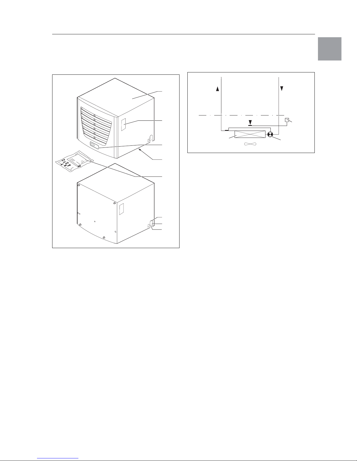
Fig. 1: Device description
Legend
1 Cover
2 Rating plate
3 Display
4 X2 master-slave connection (Comfort controller)
5 X1 terminal strip (underside of the unit)
6 X3 optional serial interface (underside of the unit)
7 Dispatch bag
8 Cooling water inlet
9 Cooling water return
10 Condensate discharge
3.1 Functional description
Air/water heat exchangers are designed and built to
dissipate heat from enclosures by cooling the air inside the enclosure and so protect the temperaturesensitive components. Air/water heat exchangers
are particularly appropriate for the temperature
range of +40°C to +70°C where comparable units,
such as air/air heat exchangers, enclosure cooling
units or filter fans, cannot be used for system reasons to effectively and economically dissipate heat
loss. It is mounted on the roof of an enclosure.
3.1.1 How it works
The air/water heat exchanger comprises of three
main components (cf. Fig. 2): Heat exchanger
package (1), fan (2) and the magnetic valve (3)
connected with each other using pipes.
Fig. 2: Air/water heat exchanger
The heat loss of the enclosure is dissipated in a
membrane heat exchanger to the water coolant.
A fan blows the internal enclosure air over the heat
exchanger (1); except for the inlet and outlet water
and the condensed water discharge, the unit is
closed to the environment.
The flow regulator (3) controls the cooling output by
changing the water flow volume depending on the
required housing temperature and the water inlet
temperature.
3.1.2 Control
Rittal enclosure air/water heat exchangers
are fitted
with a controller for setting the functions of the heat
exchanger. Depending on the design, this is either a
Basic controller (display of the operating status via
LED) or a Comfort controller (display plus extended
functions, see chapter “6 Operation” page 18).
3.1.3 Bus mode (Comfort controller only)
The serial unit interface X2 allows you to create a bus
connection with up to ten air/water heat exchangers
using the master-slave cable (shielded, four-wire
cable, Model No. SK 3124.100). This allows you to
implement the following functions:
– Parallel unit control (the air/water heat exchangers
in the network can be switched on and off simulta-
neously)
– Parallel door status message (“door open”)
– Parallel collective fault message
Data is exchanged via the master-slave connection.
During commissioning, assign an address to each
unit that also includes the identifier “master” or
“slave”.
2
4, 5, 6
9
7
3
1
10
8
Cooling water
return
Magnetic valve (3)
Temperature
control
Cooling water
inlet
Internal circuit
External circuit
Fan (2)
Heat exchanger (1)

6 Rittal air/water heat exchanger assembly instructions
3 Device description
EN
3.1.4 Safety equipment
– To protect against overcurrent and overtempera-
ture, the fan is equipped with a thermal winding
protection.
– The unit has one (in the case of the Basic control-
ler) or two (in the case of the Comfort controller) integral floating contacts on the connection terminal
(system message relay with change-over contact,
terminal 3 – 5) which may be used to retrieve messages from the heat exchanger, e.g. via PLC.
– Units with Basic and Comfort controllers are also
equipped with a condensate alarm.
3.1.5 Condensation
At high levels of humidity and low cooling water temperatures inside the enclosure, condensation may
form on the heat exchanger.
Any condensation that forms on the heat exchanger
(with high humidity and low water temperatures) is
routed to the right and/or rear out of the unit via a
drain opening in the evaporator tray. For this purpose, a hose must be connected to one of the two
condensate nozzles (see “4.4 Connecting the condensate discharge”, page 10). The drain which is not
required should be tightly sealed. The condensate
must be able to run off freely. The hose used for
draining off condensate must be laid free from kinks
and checked for correct drainage.
Units with Basic and Comfort controllers are also
equipped with a condensate alarm.
Condensate hoses are available as accessories
(refer also to the accessories section in the Rittal
Catalogue).
3.1.6 Leak detection
If a leakage or pipe breakage occurs in the water
circuit of the air/water heat exchanger, a magnetic
valve immediately stops the cooling water supply,
the floating change-over contact activated and the
fan switched off.
3.1.7 Door limit switch
The air/water heat exchanger may be operated with
a door limit switch connected. The door limit switch
is not included with the supply (available as an accessory, Model No. PS 4127.000).
The door limit switch function causes the fan and the
magnetic valve in the air/water heat exchanger to be
switched off after approximately 15 seconds when
the enclosure door is opened (contacts 1 and 2
closed). This prevents the formation of condensation
inside the enclosure while the enclosure door is
open.
The fan will start up after about 15 seconds on closure of the door. Connection is made at the terminals
1 and 2. The extra-low voltage is supplied by the internal power pack; the current is approx. 30 mA DC.
3.1.8 Additional interface X3
(Comfort controller only)
An additional interface card may be connected to
the 9-pole SUB-D connector X3 in order to incorporate the air/water heat exchanger into higher-level
monitoring systems (available as an accessory,
interface card Model No. SK 3124.200).
3.2 Proper usage
Rittal enclosure air/water heat exchangers were developed and designed in accordance with the stateof-the-art and the recognised rules governing technical safety. Nevertheless, if used improperly, they
may pose a threat to life and limb or cause damage
to property. The unit is only intended for cooling
enclosures. Any other use is deemed improper.
The manufacturer will not be liable for any damages
caused as a result of improper use, or for incorrect
assembly, installation or use. All risk is borne solely
by the user.
Proper usage also includes the observation of all
valid documents and compliance with the inspection
and servicing conditions.
Note:
The door limit switches must only
be connected free from potential.
No external voltages!
Note:
For air/water heat exchangers with basic
control, the fan continues to run even when
the door is open.
Note:
The electrical signals at the interface are of
an extra-low voltage (not extra-low safety
voltages in accordance with EN 60 335).

4 Assembly and connection
Rittal air/water heat exchanger assembly instructions 7
EN
3.3 Scope of supply
The unit is supplied in a packaging unit in a fully assembled state.
Please check the delivery for completeness:
Tab. 1: Scope of supply
4 Assembly and connection
4.1 Choosing the installation site
When choosing the installation site for the enclosure,
please observe the following:
– The air/water heat exchanger must be installed
and operated in a vertical position.
– The ambient temperature must not exceed +70°C.
– It must be possible to fit a condensate discharge
(see “4.4 Connecting the condensate discharge”,
page 10).
– It must be possible to fit a cooling water supply and
return (see “4.5 Connecting the water connection”,
page 10).
– The mains connection data as stated on the rating
plate of the unit must be guaranteed.
4.2 Assembly instructions
4.2.1 General
– Check the packaging carefully for signs of damage.
Packaging damage may be the cause of a subsequent functional failure.
– The enclosure must be sealed on all sides (IP 54).
Increased condensation will occur if the enclosure
is not airtight.
– The air inlet and outlet must not be obstructed on
the inside of the enclosure.
– In order to avoid excessive condensation inside
the enclosure, we recommend installing a door limit switch (e.g. PS 4127.000) which deactivates the
air/water heat exchanger when the enclosure door
is opened (see “3.1.7 Door limit switch”, page 6).
Qty.
Designation
1 Air/water heat exchanger
1
1
1
1
1
1
Dispatch bag:
– Plug-in terminal strip
– Sealing frame
– Assembly and installation instructions
– Assembly, installation and operating
instructions on CD-ROM
– Declaration of conformity
1 Drilling template
8 Rittal air/water heat exchanger assembly instructions
4 Assembly and connection
EN
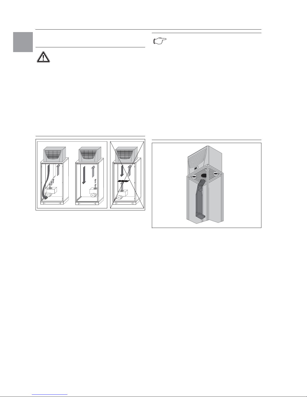
4.2.2 Layout of the electronic components
in the enclosure
Fig. 3: Never direct the cold airflow at active components
Exercise particular caution with the airflow from the
blowers of built-in electronic components (cf. Fig. 3).
Components for targeted air routing are available as
accessories – please refer to the chapter on “System
climate control” in the Rittal Catalogue.
Fig. 4: Targeted air routing inside the enclosure
Note:
Risk of condensation!
When arranging the components inside
the enclosure, please ensure that the
cold airflow from the air/water heat exchanger is not directed at active components. Please also ensure that the
cold airflow is not directed at the warm
exhaust airflow from active components
such as converters. This may lead to an
air short-circuit and therefore prevent
adequate climate control, or may even
cause the air/water heat exchanger’s
internal safety devices to cease cooling
operation.
Note:
When using an air duct system, care must
be taken to ensure that it is laid straight and
without kinks wherever possible. This minimises the resistance to the cold air flow.
It is important to ensure even air circulation
inside the enclosure. Under no circumstances should air inlet and outlet openings
be obstructed, otherwise the cooling performance of the unit will be reduced. Ensure
a suitable distance
from electronic compo-
nents and other installed
enclosures so that
the required air circulation is not obstructed
and prevented.
One cold air outlet from the air/water heat
exchanger must be kept open at all times
when operating with the air duct, to prevent
the accumulation of cold air inside the unit.
4 Assembly and connection
Rittal air/water heat exchanger assembly instructions 9
EN
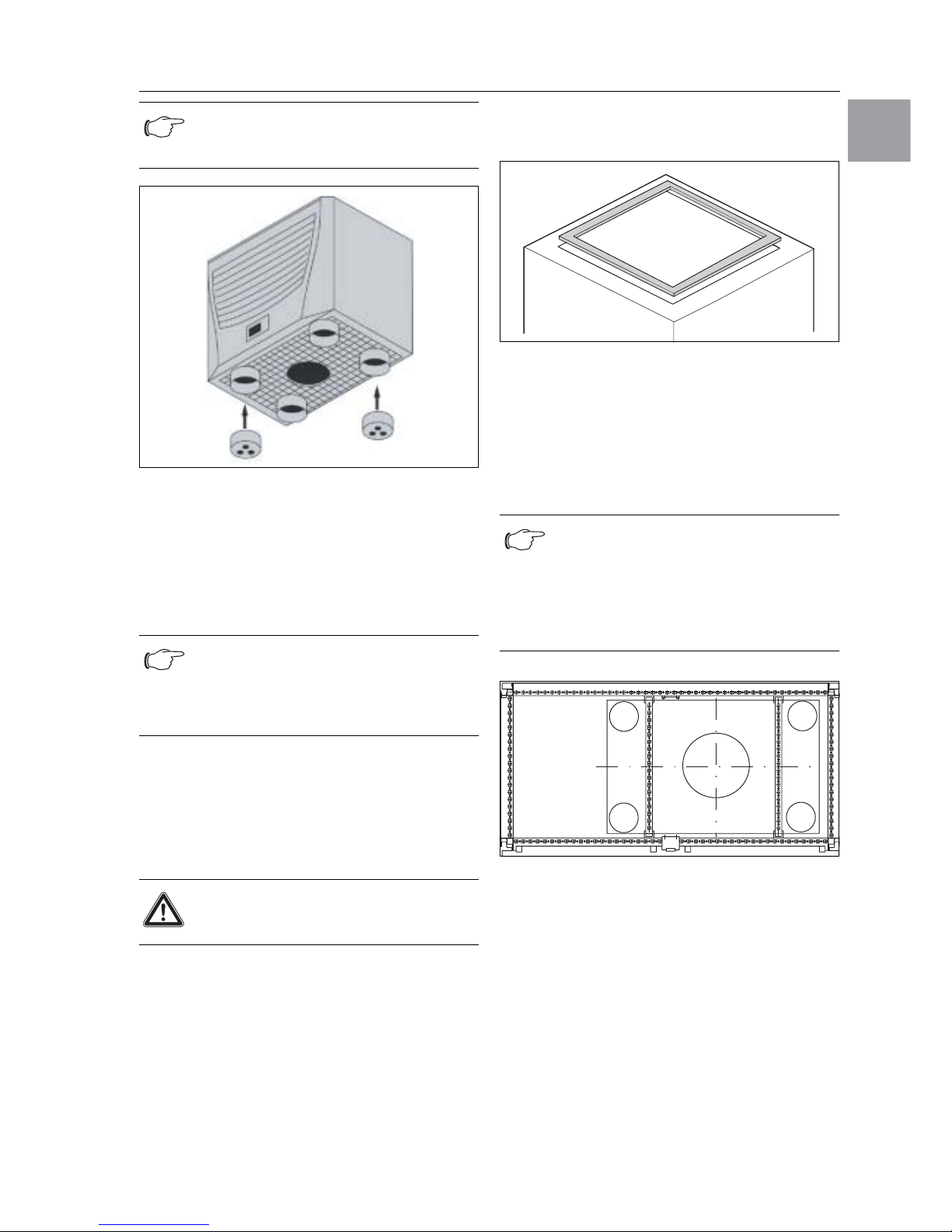
Fig. 5: Cover bungs
4.3 Assembling air/water heat exchangers
The enclosure air/water heat exchanger is fitted on
the roof of the enclosure.
To this end, the roof plate must be cut-out as per the
drilling template included with the supply.
4.3.1 Cutting out the enclosure
• Stick the supplied drilling template onto the roof of
the enclosure using adhesive tape.
There are dimensioning lines on the drilling template
to suit the installation type for your air/water heat exchanger.
• Make the cut-outs including the line width as
per the drilling template.
Deburr the cut-outs.
4.3.2 Assembling air/water heat exchangers
• Stick the supplied sealing frame onto the cut-out
roof plate.
Fig. 6: Sealing frame on roof plate
• Mount the air/water heat exchanger on the
enclosure roof.
• Screw the supplied twin-threaded bolts into the
holes in the plastic base on the underside of the
device.
• Secure the unit using the supplied washers and
nuts.
Fig. 7: Roof plate reinforcement for the TS 8 enclosure
Accessories for roof plate reinforcement with TS:
Punched rail
U nut
Fastening bracket
Threaded block
(refer also to Accessories in the Rittal Catalogue)
Note:
When using the cover bungs, no more than
2 cold air outlets should be sealed.
Note:
Pre-configured, reinforced roof plates
with cut-outs to match your enclosure are
available as accessories; refer to “System
climate control” in the Rittal Catalogue.
Risk of injury!
Carefully deburr all cut-outs to prevent
injuries caused by sharp edges.
Note:
In order to achieve a permanent seal between the air/water heat exchanger and the
enclosure, the mounting surface should be
reinforced or supported if necessary.
This is particularly applicable with large
roof areas.
10 Rittal air/water heat exchanger assembly instructions
4 Assembly and connection
EN
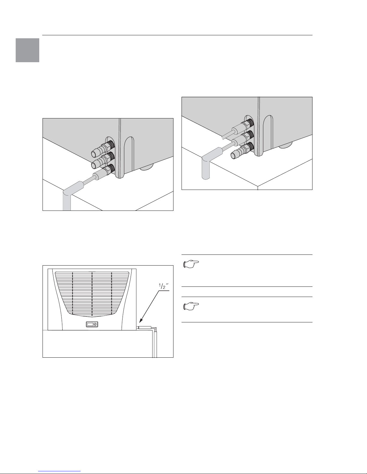
4.4 Connecting the condensate discharge
A flexible condensate discharge hose (Ø 1/2˝) can be
fitted to the air/water heat exchanger.
The condensate discharge
– must be laid with a suitable and constant gradient
(no siphoning)
– must be laid without kinks
– must not have a reduced cross-section if extend-
ed.
The condensate hose is available as an accessory
(refer also to Accessories in the Rittal Catalogue).
Fig. 8: Connect the condensate discharge to the side
of the unit
• Connect a suitable hose from the right or rear to the
condensate nozzle screwed into the unit, and
secure it with a hose clip (with 2 Nm torque).
• Lay the condensate hose, e.g. into a drain.
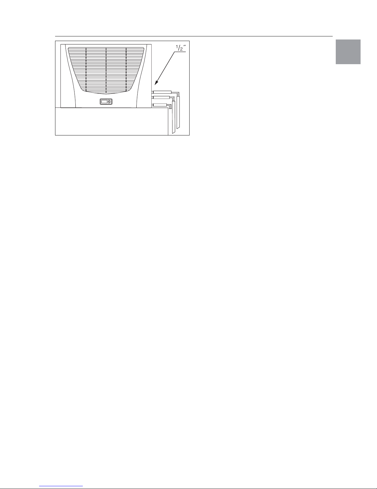
Fig. 9: Lay the condensate discharge to the side of the unit
4.5 Connecting the water connection
A compression-proof flexible condensate discharge
hose (Ø 1/2˝) for both the supply and the return can
be fitted to the air/water heat exchanger.
The cooling water hose
– must be laid without kinks
– must not have a reduced cross-section if extended
and, if necessary, must be insulated.
Fig. 10: Connect the cooling water inlet (top) and
return (centre) to the side of the unit
• Reseal the connection nozzles using teflon tape or
hemp and sealing paste.
• Connect a suitable hose to each of the two cooling
water connection nozzles (at the side or rear of the
unit) and secure each one with a hose clip (with
15 Nm torque).
The unused cooling water connecting pieces must
be closed appropriately with sealing bungs (with
15 Nm torque).
Note:
The water circuit should be protected from
ingress of dirt or excess pressure (maximum permitted operating pressure 10 bar)!
Note:
Observe the flow direction and check
for leaks!
4 Assembly and connection
Rittal air/water heat exchanger assembly instructions 11
EN
Fig. 11: Lay the cooling water hose
4.5.1 Notes on water quality
To ensure the reliable operation of the above-mentioned units, the VBG guidelines for cooling water
must be observed (VGB-R 455 P).
The cooling water must not contain any limescale deposits or loose debris; in other words, it should have
a low level of hardness, in particular, a low level of
calcium hardness.
In particular, for recooling within
the plant, the calcium hardness should not be too
high. On the other hand, the water should not be so
soft that it attacks the materials. When recooling the
cooling water, the salt content should not be allowed
to increase excessively due to the evaporation of
large quantities of water, since electrical conductivity increases as the concentration of dissolved substances rises, and the water thereby becomes more
corrosive.
• Always add the appropriate volume of fresh water.
• Always remove part of the enriched water.
The following criteria for the cooling water must be
observed:
– Water with high gypsum content is unsuitable for
cooling purposes because it has a tendency to
form boiler scale that is particularly difficult to remove.
– The cooling water should be free from iron and
manganese, because otherwise deposits may occur that accumulate in the pipes and block them.
– At best, organic substances should only be
present in small quantities, because otherwise
sludge deposits and microbiological contamination may occur.
4.6 Notes on electrical installation
When performing the electrical installation, it is important to observe all valid national and regional regulations as well as the provisions of the responsible
power supply company. The electrical installation
may only be performed by a qualified electrician who
is responsible for compliance with the applicable
standards and regulations.
4.6.1 Connection data
– The connected voltage and frequency must corre-
spond to the values stated on the rating plate.
– The air/water heat exchanger must be connected
to the mains via an all-pin isolating device that
ensures at least 3 mm contact opening when
switched off.
– No additional temperature control may be con-
nected upstream of the unit at the supply end.
– Install the pre-fuse specified on the rating plate
(miniature circuit-breaker “K” characteristic or slow
fuse) to protect the cable and equipment from
short-circuits.
– The mains connection must ensure low-noise
potential equalisation.
4.6.2 Overvoltage protection
and supply line load
– The unit does not have its own overvoltage protec-
tion. Measures must be taken by the operator at
the supply end to ensure effective lightning and
overvoltage protection. The mains voltage must
not exceed a tolerance of ±10%.
– In accordance with IEC 61 000-3-11, the unit is
intended solely for use at sites with a continuous
current-carrying capacity (incoming mains power
supply) of more than 100 A per phase and with
a supply voltage of 400/230 V. If necessary, the
power supply company must be consulted to ensure that the continuous current-carrying capacity
at the point of connection to the public grid is
sufficient for connection of such a unit.
– The fans in single- and three-phase units are intrin-
sically safe (thermal winding protection). The same
also applies to all transformer versions and to special-voltage units which are likewise equipped with
a transformer.
– Install the slow pre-fuse specified on the rating
plate (miniature circuit-breaker with “K” characteristic, motor circuit-breaker or transformer circuitbreaker) to protect the cable and equipment from
short-circuits. Select a suitable motor circuitbreaker/transformer circuit-breaker in accordance
with the information specified on the rating plate:
Set it to the minimum specified value. This will
achieve the best short-circuit protection for cables
and equipment. Example: Specified setting range
MS/TS 6.3 – 10 A; set to 6.3 A.

12 Rittal air/water heat exchanger assembly instructions
4 Assembly and connection
EN
4.6.3 Door limit switch
– Each door limit switch must only be assigned to
one air/water heat exchanger.
– Several door limit switches may be connected
in parallel and operated on one air/water heat
exchanger.
– The minimum cross-section of the connection
cable is 0.3 mm2 for a cable length of 2 m.
We recommend the use of a shielded cable.
– The line resistance to the door limit switch must not
exceed a maximum of 50 Ω.
– The door limit switch only supports a floating
connection; no external voltages.
– The contact of the door limit switch must be closed
when the door is open.
The safety extra-low voltage for the door limit switch
is provided by the internal power pack: Current
approx. 30 mA DC.
• Connect the door limit switch to terminals 1 and 2
of the connector.
4.6.4 Notes on the flicker standard
The flicker limits specified in standard EN 61 0003-3 or -3-11 are adhered to, provided the supply
impedance is less than approx. 1.5 Ω.
Where necessary, the unit operator should measure
the connected impedance or consult the responsible
power supply company. If there is no way of influencing the supply impedance and sensitive installed
components (e.g. BUS) are subjected to interference, a line reactor or starting-current limiting device
should be connected upstream of the air/water heat
exchanger to restrict the startup current of the air/
water heat exchanger.
4.6.5 Potential equalisation
Rittal recommends connecting a conductor with a
nominal cross-section of at least 6 mm2 to the potential equalisation connection point on roof-mounted
air/water heat exchangers and incorporating it into
the existing potential equalisation system. According
to the standard, the PE conductor in the mains connection cable is not classified as an equipotential
bonding conductor.
 Loading...