

Rittal SK 3209.100, SK 3209.110, SK 3209.140, SK 3210.100, SK 3210.140 Assembly And Operating Instructions Manual
...
Air/water heat exchangers
SK 3209.XXX
SK 3210.XXX
Assembly and operating instructions

Contents
EN
Contents
1 Notes on documentation .................. 3
1.1 CE label ....................................................... 3
1.2 Storing the documents................................. 3
1.3 Symbols used in these operating instructions 3
1.4 Other applicable documents ........................ 3
2 Safety instructions ............................ 3
3 Device description ............................ 4
3.1 Functional description .................................. 4
3.1.1 How it works ......................................................... 4
3.1.2 Control .................................................................. 4
3.1.3 Bus mode (e-Comfort controller only) .................... 5
3.1.4 Safety equipment .................................................. 5
3.1.5 Condensation ....................................................... 5
3.1.6 Leak detection ...................................................... 5
3.1.7 Door limit switch (e-Comfort controller only) .......... 5
3.1.8 Additional interface X3 (e-Comfort controller only) . 5
3.2 Proper use, foreseeable misuse ................... 5
3.3 Scope of supply........................................... 5
4 Installation ........................................ 6
4.1 Safety instructions........................................ 6
4.2 Choosing the installation site ........................ 6
4.3 Assembly procedure .................................... 6
4.3.1 Assembly instructions ........................................... 6
4.3.2 Make a mounting cut-out ...................................... 7
4.3.3 Assembling the air/water heat exchanger .............. 7
4.3.4 Connecting the condensate discharge .................. 8
4.4 Connecting the water connection................. 9
4.4.1 Connection on the side of the unit ......................... 9
4.4.2 Connection on the rear of the unit ......................... 9
4.4.3 Notes on water quality ........................................ 10
4.4.4 Preparation and maintenance of the water in
recooling systems ............................................... 10
4.5 Electrical connection .................................. 10
4.5.1 Notes on electrical installation ............................. 10
4.5.2 Door limit switch (e-Comfort controller only) ........ 11
4.5.3 Potential equalisation .......................................... 11
4.5.4 Install the power supply ....................................... 11
6.2.2 Launching test mode .......................................... 17
6.2.3 General programming information ....................... 17
6.2.4 Eco-mode ........................................................... 18
6.2.5 Editable parameters ............................................ 19
6.2.6 Bus connection (only when interconnecting several
units with an e-Comfort controller) ...................... 19
6.2.7 Programming overview of e-Comfort controller ... 21
6.2.8 Defining system messages for evaluation ............ 22
6.2.9 Setting the Master-slave identifier ........................ 22
6.2.10 Evaluating system messages .............................. 23
7 Inspection and maintenance .......... 24
8 Emptying, storage and disposal ..... 26
9 Technical specifications ................. 27
10 List of spare parts .......................... 29
11 Hydrological data ........................... 30
12 Appendix ....................................... 31
12.1 Characteristic curves.................................. 31
12.2 Dimensions ................................................ 33
13 Declaration of conformity ............... 34
5 Commissioning ............................... 14
6 Operation ....................................... 14
6.1 Control using the Basic controller............... 14
6.1.1 Display and system analysis ................................ 14
6.1.2 Properties ........................................................... 14
6.1.3 General programming information ....................... 14
6.1.4 Operation of the basic controller ......................... 14
6.1.5 Setting the temperature ...................................... 14
6.1.6 Setting of system messages ............................... 14
6.1.7 Programming and control of the Basic controller . 15
6.1.8 Reset of r6 and r7 (min./max. internal
temperature) ....................................................... 15
6.1.9 System message contact (K1; floating) ................ 15
6.1.10 Programming overview of Basic controller ........... 16
6.2 Control using the e-Comfort controller ....... 17
6.2.1 Properties ........................................................... 17
2 Rittal air/water heat exchangers
1 Notes on documentation
1 Notes on documentation
1.1 CE label
Rittal GmbH & Co. KG confirms the conformity of the air/
water heat exchanger with the European Union's Machinery Directive 2006/42/EC and EMC Directive 2014/
30/EU. A corresponding declaration of conformity has
been issued and enclosed with the unit.
1.2 Storing the documents
The assembly and operating instructions as well as all
other applicable documents are an integral part of the
product. They must be issued to everyone who works
with the air/water heat exchanger and must always be
available and on hand for operating and maintenance
personnel.
1.3 Symbols used in these operating instructions
The following symbols are used in this documentation:
Warning!
Hazardous situation which may lead to
death or serious injury if the instructions
are not followed.
Caution!
Hazardous situation which may lead to
(minor) injuries if the instructions are not
followed.
2 Safety instructions
Please observe the following general safety notes when
assembling and operating the unit:
– Assembly, installation and servicing may only be per-
formed by properly trained specialists.
– The minimum water inlet temperature of +1°C must
not be reduced at any point in the water cycle. Otherwise there is danger of frost damage!
– Use antifreeze agents only with the manufacturer's
consent.
– Do not obstruct the air inlet and air outlet of the air/wa-
ter heat exchanger inside the enclosure (see section4.3.1 "Assembly instructions").
– The heat loss of the components installed in the enclo-
sure must not exceed the specific useful cooling output of the air/water heat exchanger.
– The air/water heat exchanger must always be trans-
ported in a vertical position.
– Use only original spare parts and accessories.
– Do not make any changes to the air/water heat ex-
changer other than those described in these instruc-
tions or associated instructions.
– The mains connector of the air/water heat exchanger
must only be connected and disconnected with the
system de-energised. Connect the pre-fuse specified
on the rating plate.
Other than these safety instructions, ensure you also
observe the specific safety instructions when perform-
ing the tasks described in the following chapters.
EN
Attention!
Potential threat to the product and the
environment.
Note:
Important notices and indication of situations
which may result in material damage.
This symbol indicates an "Action Point" and shows
that you should perform an operation/procedure.
1.4 Other applicable documents
Assembly and operating instructions exist as paper documents for the air/water heat exchanger described here
and are enclosed with the equipment.
We cannot accept any liability for damage associated
with failure to observe these instructions. Where applicable, the instructions for any accessories used also apply.
Rittal air/water heat exchangers 3
3 Device description
12
13
14
15
17 16
11
EN
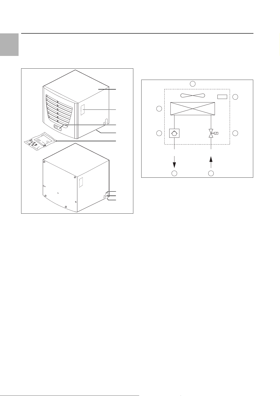
3 Device description
Depending on the model chosen, your air/water heat exchanger may vary in appearance from the illustrations
contained in these instructions. However, the functions
are identical in principle.
1
2
3
4, 5, 6
7
3.1.1 How it works
The air/water heat exchanger comprises three main
components (see fig.2):
– Heat exchanger package (item 2),
– fan (item 3) and
– magnetic valve (item 5),
connected with each other using pipes.
Fig. 2: Air/water heat exchanger
8
9
10
Fig. 1: Device description
Key
1Cover
2Rating plate
3Display
4 X2 master/slave connection (e-Comfort controller)
5 X1 terminal strip (underside of the unit)
6 X3 optional serial interface (underside of the unit)
7 Dispatch bag
8 Cooling water inlet
9 Cooling water return
10 Condensate discharge
Key
1Non-return valve
2 Heat exchanger
3Fan
4 Temperature control
5Magnetic valve
6 Cooling water inlet
7 Cooling water return
The heat loss of the enclosure is dissipated in a membrane heat exchanger to the water coolant. A fan
(item 3) blows the internal enclosure air over the heat exchanger (item 2); except for the inlet and outlet water
and the condensed water discharge, the unit is closed
to the environment.
The magnetic valve (item 5) controls the cooling output
by changing the water flow volume depending on the required target temperature and the water inlet tempera-
3.1 Functional description
ture.
Air/water heat exchangers are designed and built to dissipate heat from enclosures by cooling the air inside the
enclosure and so protect the temperature sensitive
components.
Air/water heat exchangers are particularly appropriate
for the temperature range of up to +70°C where comparable units, such as air/air heat exchangers, enclosure
3.1.2 Control
Rittal air/water heat exchangers are fitted with a control-
ler for setting the functions of the heat exchanger. De-
pending on the design, this is either a Basic controller or
an e-Comfort controller (display plus extended func-
tions, see section 6 "Operation").
cooling units or fan-and-filter units, cannot be used for
system reasons to effectively and economically dissipate
heat loss. It is mounted on the roof of an enclosure.
4 Rittal air/water heat exchangers
3 Device description
3.1.3 Bus mode (e-Comfort controller only)
The serial interface X2 allows you to create a bus connection with up to ten air/water heat exchangers using
the master-slave cable (shielded, four-wire cable, Model
No. 3124.100).
This allows you to implement the following functions:
– Parallel unit control (the air/water heat exchangers in
the network can be switched on and off simultaneous-
ly)
– Parallel door status message ("door open")
– Parallel collective fault message
Data is exchanged via the master-slave connection.
During commissioning, assign an address to each unit
that also includes the identifier "master” or "slave” (see
section6.2.9 "Setting the Master-slave identifier").
3.1.4 Safety equipment
– To protect against overcurrent and overtemperature,
the fan is equipped with a thermal winding protection.
– The device has floating contacts on the connection
pins (terminals 1 – 3), via which system messages
from the device may be polled, e.g. using a PLC (1 x
change-over contact Basic controller, 2 x normally
open contacts e-Comfort controller).
– The air/water heat exchanger has a leak and conden-
sate warning.
3.1.5 Condensation
At high levels of humidity and low cooling water temperatures inside the enclosure, condensation may form on
the heat exchanger.
Any condensation that forms on the heat exchanger
(with high humidity and low water temperatures) is routed to the right and/or rear out of the unit via a drain
opening in the plastic tray. For this purpose, a hose must
be connected to one of the two condensate nozzles (see
section 4.3.4 "Connecting the condensate discharge").
The drain which is not required should be tightly sealed.
The condensate must be able to run off freely. The hose
used for draining off condensate must be laid free from
kinks and checked for correct drainage.
Condensate hoses are available as accessories (refer
also to the accessories section in the Rittal Catalogue).
3.1.6 Leak detection
If a leakage or pipe breakage occurs in the water circuit
of the air/water heat exchanger, a magnetic valve stops
the cooling water supply and the fault signal contact is
activated. For units with e-Comfort controller, the fans
are switched off additionally.
Basic controller: The warning "IA" appears on the display.
e-Comfort controller: The warning "A08" appears on the
display.
3.1.7 Door limit switch (e-Comfort controller only)
The air/water heat exchanger may be operated with a
door limit switch connected.The door limit switch is not
included with the supply (available as an accessory,
Model No. 4127.010).
The door limit switch function causes the fan and the
magnetic valve in the air/water heat exchanger to be
switched off after approximately 15 seconds when the
enclosure door is opened (contacts 1 and 2 closed). This
prevents the formation of condensation inside the enclosure while the enclosure door is open.
The fan will start up after about 15 seconds on closure
of the door.
Note:
The door limit switches must only be connected free from potential. No external voltages!
3.1.8 Additional interface X3 (e-Comfort controller only)
Note:
The electrical signals at the interface are of an
extra-low voltage (not extra-low safety voltages to EN 60 335).
An additional interface card may be connected to the 9pole SUB-D connector X3 in order to incorporate the air/
water heat exchanger into higher-level monitoring systems (available as an accessory, interface card Model
No. 3124.200).
3.2 Proper use, foreseeable misuse
The air/water heat exchanger is designed for cooling
closed enclosures. Under no circumstances should the
limit values specified in the technical specifications (see
section9) be exceeded. Assembly, installation and servicing may only be performed by properly trained specialists.
Improper use may cause hazards. Improper use may be
for example:
– Use of the cooling unit for a long period with an open
enclosure
– Use of accessories not approved by Rittal GmbH &
Co. KG
– Use of an incorrect cooling medium
3.3 Scope of supply
The unit is supplied in a packaging unit in a fully assembled state.
Please check the scope of supply for completeness.
Qty. Description
EN
1 Air/water heat exchanger
Tab. 1: Scope of supply
Rittal air/water heat exchangers 5
4 Installation
EN
Qty. Description
1 Dispatch bag:
1 – Plug-in terminal strip
1 – Sealing frame
1 – Sealing plate
1 – Assembly and installation instructions
2 – Hose sleeves (1/2")
2 – Sealing ring (R 3/8")
11 – Twin-threaded bolt including assembly
parts
5–Screw-in elbow
1 – Angle screw socket
1 – Right-angle connector
1 Drilling template
Tab. 1: Scope of supply
4 Installation
4.1 Safety instructions
Warning!
Please observe the maximum permissi-
ble weight to be lifted by one person.
Use suitable lifting devices, if needed.
Warning!
Work on electrical systems or equip-
ment may only be carried out by an electrician or by trained personnel under the
guidance and supervision of an electrician. All work must be carried out in accordance with electrical engineering
regulations.
The air/water heat exchanger may only
be connected after the aforementioned
personnel have read this information!
Warning!
The air/water heat exchanger must be
connected to the mains via an all-pole
disconnecting device to overvoltage
categoryIII (IEC 61 058-1).
The air/water heat exchanger is not deenergised until all of the voltage sources
have been disconnected!
4.2 Choosing the installation site
When choosing the installation site for the enclosure,
please observe the following:
– The air/water heat exchanger must be installed and
operated in a vertical position.
– The ambient temperature must not exceed +70°C.
– It must be possible to fit a condensate discharge (see
section4.3.4 "Connecting the condensate dis-
charge").
– It must be possible to fit a cooling water supply and re-
turn (see section 4.4 "Connecting the water connec-
tion").
– The mains connection data as stated on the rating
plate of the unit must be guaranteed.
4.3 Assembly procedure
4.3.1 Assembly instructions
Check the packaging carefully for signs of damage.
Packaging damage may be the cause of a subsequent
functional failure.
– The enclosure must be sealed on all sides (IP 54). In-
creased condensation will occur if the enclosure is not
airtight.
– The air inlet and outlet must not be obstructed on the
inside of the enclosure.
– In order to avoid excessive condensation inside the
enclosure, we recommend installing a door limit
switch (e.g. 4127.010) which deactivates the air/water
heat exchanger when the enclosure door is opened
(see section 3.1.7 "Door limit switch (e-Comfort con-
troller only)").
Use only insulated tools.
The connection regulations of the appropriate power supply company are to
be followed.
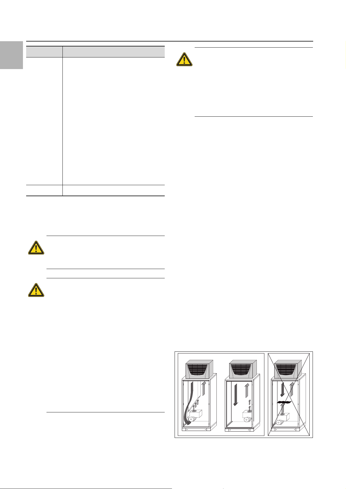
Fig. 3: Never direct the cold airflow at active components
6 Rittal air/water heat exchangers
When arranging the components inside the enclosure,
please ensure that the cold airflow from the air/water
heat exchanger is not directed at active components.
Please also ensure that the cold airflow is not directed
at the warm exhaust airflow from active components
such as converters.
This may lead to an air short-circuit and therefore prevent adequate climate control, or may even cause the
air/water heat exchanger's internal safety devices to
cease cooling operation.
Exercise particular caution with the airflow from the
blowers of built-in electronic components (fig. 3).
Components for targeted air routing are available as
accessories – please refer to the Rittal Catalogue.
When using an air duct system, care must be taken to
ensure that it is laid straight and without kinks wherever possible.
This minimises the resistance to the cold airflow.
It is important to ensure even air circulation inside the
enclosure.
Under no circumstances should air inlet and outlet
openings be obstructed, otherwise the cooling performance of the unit will be reduced.
Ensure a suitable distance from electronic components and other installed enclosures so that the required air circulation is not obstructed and prevented.
– One cold air outlet from the air/water heat exchanger
must be kept open at all times when operating with the
air duct, to prevent the accumulation of cold air inside
the unit.
4 Installation
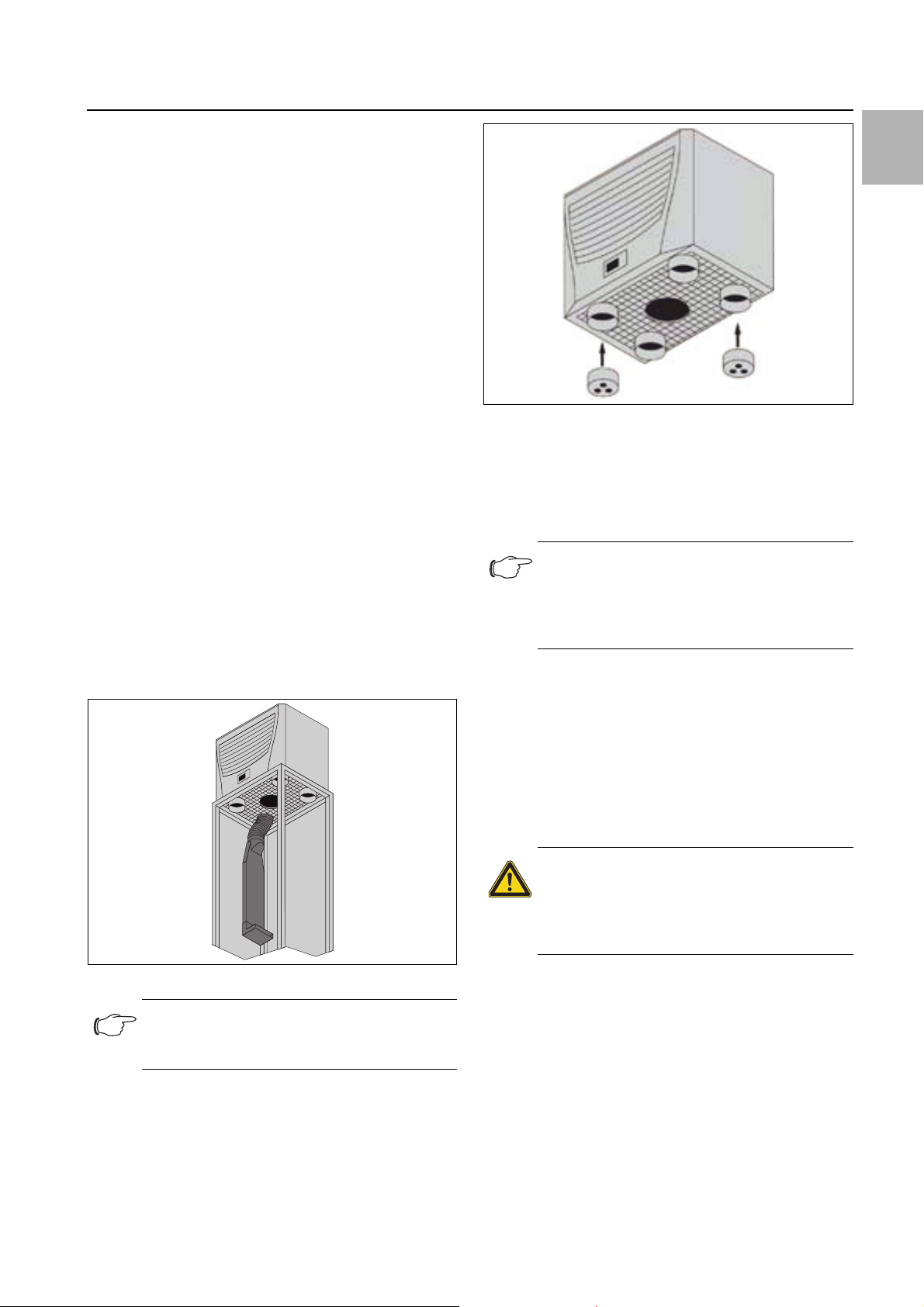
Fig. 5: Cover bungs
4.3.2 Make a mounting cut-out
The enclosure air/water heat exchanger is fitted on the
roof of the enclosure. To this end, the roof plate must be
cut out as per the drilling template included with the supply.
Note:
Pre-configured, reinforced roof plates with
cut-outs to match your enclosure are available as accessories; refer to the Rittal Catalogue.
Stick the supplied drilling template onto the roof of the
enclosure using adhesive tape.
There are dimensioning lines on the drilling template to
suit the installation type for your air/water heat exchanger.
Drill all the required holes and make the mounting cutout.
Carefully deburr all drilled holes and the cut-out to prevent injuries caused by sharp edges.
EN
Caution!
Drilled holes and cut-outs that have not
been fully deburred may cause cut injuries, particularly when assembling the
cooling unit.
Fig. 4: Targeted air routing inside the enclosure
Note:
4.3.3 Assembling the air/water heat exchanger
Stick the supplied sealing frame onto the cut out roof
plate.
When using the cover bungs, no more than
2 cold air outlets should be sealed.
Rittal air/water heat exchangers 7
EN
4 Installation
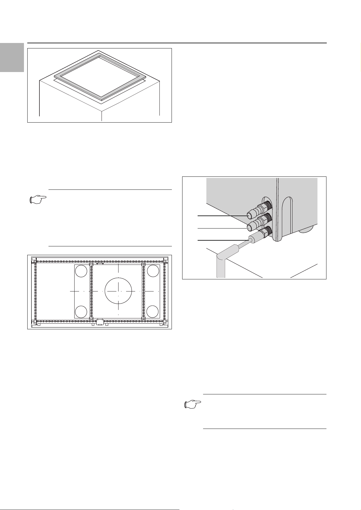
Fig. 6: Sealing frame on roof plate
Stick the supplied sealing plate onto the underside of
the unit.
Mount the air/water heat exchanger on the enclosure
roof.
Screw the supplied twin-threaded bolts into the holes
in the plastic base on the underside of the device.
Secure the unit using the supplied washers and nuts.
Note:
In order to achieve a permanent seal be-
tween the air/water heat exchanger and the
enclosure, the mounting surface should be
reinforced or supported if necessary.
This is particularly applicable with large roof
areas.
Accessories for roof plate reinforcement with TS
(refer also to Accessories in the Rittal Catalogue):
– Punched rail
–U nut
– Fastening bracket
– Threaded block
4.3.4 Connecting the condensate discharge
A flexible condensate discharge hose Ø 12mm (½") can
be fitted to the air/water heat exchanger.
The condensate discharge
– must be laid with a suitable and constant gradient (no
siphoning)
– must be laid without kinks
– must not have a reduced cross-section if extended
The condensate hose is available as an accessory (refer
also to Accessories in the Rittal Catalogue).
1
2
3
Fig. 7: Roof plate reinforcement for the TS 8 enclosure
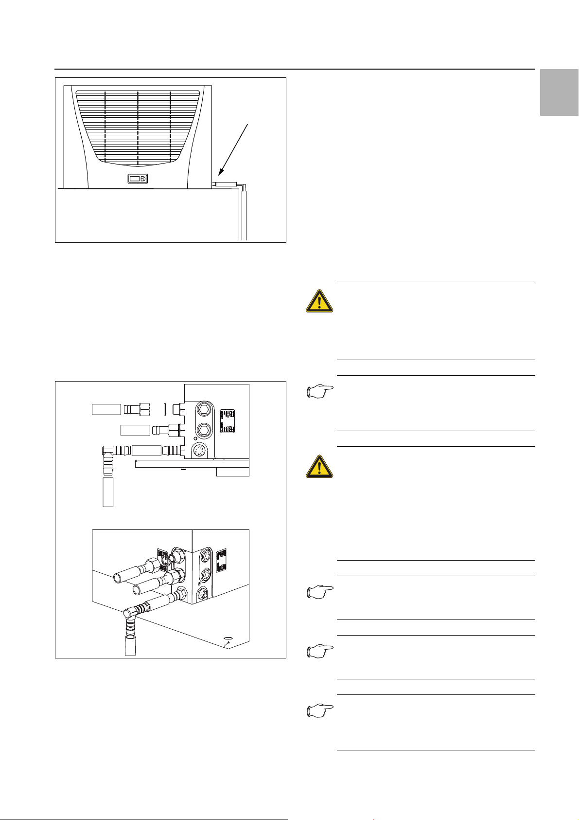
Fig. 8: Connect the condensate discharge to the side of the
unit
Key
1Cooling water connection (inlet)
2 Cooling water connection (return)
3 Condensate water discharge
Connect a suitable hose from the right or rear to the
condensate nozzle screwed into the unit, and secure
it with a hose clip (with 2 Nm torque).
Lay the condensate hose, e.g. into a drain.
Alternatively, the condensate discharge can also be
connected on the rear of the unit.
In this case, proceed as described in section 4.4.2
"Connection on the rear of the unit".
Note:
To avoid kinking of the condensate hose, use
the angled connector contained in the scope
of supply.
8 Rittal air/water heat exchangers
Ø 12 mm (½")
Fig. 9: Lay the condensate discharge to the side of the unit
4.4 Connecting the water connection
A compression-proof flexible condensate discharge
hose Ø 12 mm (1/2") for both the supply and the return
can be fitted to the air/water heat exchanger.
The cooling water hose
– must be laid without kinks
– must not have a reduced cross-section if extended
and
– must be insulated, if necessary.
4 Installation
When doing so, ensure that the pre-assembled screw
connector is not loosened from the unit (SW 22 spanner).
Connect a suitable hose to each of the two cooling
water connection nozzles (at the side or rear of the
unit) and secure each one with a hose clip (with 25 Nm
torque).
4.4.2 Connection on the rear of the unit
Remove the sealing bung.
Screw-in the threaded connector that is far from the
device side and seal the joints with Teflon tape or
hemp and sealing compound.
Proceed as described in section 4.4.1 "Connection on
the side of the unit".
Subsequently use the sealing bungs to close the open
connector holes on the side of the unit.
Warning!
Switch off the power supply to the air/
water heat exchanger before working on
the water circuit and take suitable precautions against it being accidentally
switched on again.
Note:
The water circuit should be protected from
ingress of dirt or excess pressure (maximum
permitted operating pressure 10 bar)!
EN
Fig. 10: Connect the cooling water inlet (top) and return (centre)
to the side of the unit
4.4.1 Connection on the side of the unit
Push the sealing rings onto the screw connector and
tighten the nozzles contained in the accessory pack
with min. 25 Nm and max. 30 Nm.
Attention!
Volumetric flows > 400 l/h may cause
damage to the device. Suitable measures should be taken to regulate the volumetric flow, such as flow regulator
valves (Model Nos. 3301.930/.940,
3201.990). Damage caused by excessive
volumetric flows will not be covered by
Rittal's warranty.
Note:
No considerable increase in cooling output is
achieved with flow rates > 400 l/h.
Note:
Observe the flow direction and check for
leaks!
Note:
The unused cooling water connecting pieces
must be closed appropriately with sealing
bungs.
Rittal air/water heat exchangers 9

4 Installation
EN
The units do not have any separate ventilation.
For pressure-sealed systems, install the appropriate
ventilation equipment on the water side.
4.4.3 Notes on water quality
To ensure the reliable operation of the above-mentioned
units, the VBG guidelines for cooling water must be observed (VGB R 455 P).
The cooling water must not contain any limescale deposits; in other words, it should have a low level of hardness, in particular, a low level of calcium hardness. In
particular, for recooling within the plant, the calcium
hardness should not be too high. On the other hand, the
water should not be so soft that it attacks the materials.
When recooling the cooling water, the salt content
should not be allowed to increase excessively due to the
evaporation of large quantities of water, since electrical
conductivity increases as the concentration of dissolved
substances rises, and the water thereby becomes more
corrosive.
Always add the appropriate volume of fresh water.
Always remove part of the enriched water.
The following criteria for the cooling water must be observed:
– Water with high gypsum content is unsuitable for cool-
ing purposes because it has a tendency to form boiler
scale that is particularly difficult to remove.
– The cooling water should be free from iron and man-
ganese, otherwise deposits may occur that accumulate in the pipes and block them.
– At best, organic substances should only be present in
small quantities, otherwise sludge deposits and microbiological contamination may occur.
4.4.4 Preparation and maintenance of the water in recooling systems
Depending on the type of installation to be cooled, certain requirements are placed on the cooling water with
respect to purity. According to the level of contamination
and the size and design of the recooling systems, a suitable process is used to prepare and/or maintain the water.
The most common types of contamination and most frequently used techniques to eliminate them in industrial
cooling are:
Contamination of the
water
Mechanical contamination Filter the water using:
Excessive hardness Water softening via ion ex-
Tab. 2: Contamination and procedures for eliminating it
Procedure
– Mesh filter
– Gravel filter
– Cartridge filter
– Precoated filter
change
Contamination of the
water
Moderate content of mechanical contaminants and
hardeners
Moderate content of chemical contaminants
Biological contaminants,
slime bacteria and algae
Tab. 2: Contamination and procedures for eliminating it
Procedure
Addition of stabilisers and/
or dispersing agents to the
water
Addition of passifiers and/or
inhibitors to the water
Addition of biocides to the
water
4.5 Electrical connection
4.5.1 Notes on electrical installation
When carrying out the electrical installation, it is important to observe all valid national and regional regulations as well as the provisions of the responsible
power supply company.
The electrical installation must comply with EN 61 439
and may only be carried out by a qualified electrician
who is responsible for compliance with the applicable
standards and regulations.
Connection data
– The connected voltage and frequency must corre-
spond to the values stated on the rating plate.
– The air/water heat exchanger must be connected to
the mains via a category III all-pole disconnecting device (IEC 61 058-1) that ensures at least 3 mm contact
opening when switched off.
– No additional temperature control may be connected
upstream of the unit at the supply end.
– The mains connection must ensure low-noise poten-
tial equalisation.
Overvoltage protection and supply line load
– The unit does not have its own overvoltage protection.
Measures must be taken by the operator at the supply
end to ensure effective lightning and overvoltage protection. The mains voltage must not exceed a tolerance of ±10%.
– In accordance with IEC 61 000-3-11, the unit is in-
tended solely for use at sites with a continuous current-carrying capacity (incoming mains power supply)
of more than 100 A per phase and with a supply voltage of 400/230 V. If necessary, the power supply
company must be consulted to ensure that the continuous current-carrying capacity at the point of connection to the public grid is sufficient for connection of
such a unit.
– The fans in single- and three-phase units are intrinsi-
cally safe (thermal winding protection). The same also
applies to all transformer versions and to special-voltage units which are likewise equipped with a transformer.
10 Rittal air/water heat exchangers

Install the pre-fuse specified on the rating plate to protect the cable and equipment from short circuits.
Select a suitable motor circuit-breaker/transformer circuit-breaker in accordance with the information specified in the rating plate: Set it to the rated current.
This will achieve the best short-circuit protection for
cables and equipment.
Example: Specified setting range MS/TS 6.3 – 10A;
set to 6.3A.
4.5.2 Door limit switch (e-Comfort controller only)
– Each door limit switch must only be assigned to one
air/water heat exchanger.
– Several door limit switches may be connected in par-
allel and operated on one air/water heat exchanger.
– The minimum cross-section for the connection cable
is 0.3 mm
the use of a shielded cable.
– The line resistance to the door limit switch must not
exceed a maximum of 50 Ω.
– The door limit switch only supports a floating connec-
tion; no external voltages.
– The contact of the door limit switch must be closed
when the door is open.
The safety extra-low voltage for the door limit switch is
provided by the internal power pack: Current approx.
30 mA DC.
Connect the door limit switch to terminals 1 and 2 of
the connector.
2
for a cable length of 2 m. We recommend
4 Installation
EN
Note:
The door limit switch is available as an acces-
sory (Model No. 4127.010).
4.5.3 Potential equalisation
If, for EMC reasons, the unit is to be integrated into the
customer's existing potential equalisation system, a
conductor can be connected to the potential equalisation connection point. The connection point is marked
with a schematic symbol.
Note:
According to the standard, the PE conductor
in the mains connection cable is not classified
as an equipotential bonding conductor.
4.5.4 Install the power supply
Use the electrical circuit diagram to complete the elec-
trical installation within the air/water heat exchanger.
If you would like the system messages from the air/
water heat exchanger to be evaluated via the system
message relay, you should also connect a suitable
low-voltage cable to connection terminals 3 – 5 (1 x
change-over contact Basic controller, 2 x normally
open contacts e-Comfort controller).
Rittal air/water heat exchangers 11
 Loading...