

Page 1
HDAMB
Overview
User’s Guide
Version: 0.70
Release Date: July 2003
Install
Hardware
BIOS
Setup
Appendix
Page 2

AccelerTech ServerBoard Manual
COPYRIGHTS AND DISCLAIMERS.......................................... C-I
Overview
GENERAL SAFETY PRECAUTIONS.......................................C-2
ESD PRECAUTIONS ........................................................C-2
OPERATING PRECAUTIONS................................................C-2
ABOUT THIS USER'S MANUAL ...........................................C-3
GETTING HELP ...............................................................C-3
WORKSTATIONBOARD SPECIFICATIONS ..............................C-5
MAINBOARD LAYOUT ......................................................C-6
MAINBOARD MAP...........................................................C-7
I/O PORT ARRAY ...........................................................C-7
Hardware Installation
MAP OF JUMPERS...........................................................C-9
JUMPER SETTINGS ..........................................................C-9
INSTALLING MEMORY .....................................................C-10
RECOMMENDED MEMORY CONFIGURATIONS ......................C-12
INSTALLING THE PROCESSOR AND HEATSINK .....................C-13
THE AGP PRO SLOT ...................................................C-15
MAP OF MAINBOARD CABLE CONNECTORS ......................C-16
ATX POWER CONNECTORS ............................................C-17
PRIMARY IDE CONNECTORS ...........................................C-18
FLOPPY DISK DRIVE CONNECTOR ...................................C-18
FRONT PANEL SWITCHES ..............................................C-19
FRONT/BACK/CPU/AUX FAN CONNECTORS .....................C-20
REAR PANEL I/O PORTS ...............................................C-21
ADDITIONAL I/O CONNECTORS........................................C-22
INSTALLING EXPANSION CARDS .......................................C-23
PROMISE CHIPSET AND SERIAL ATA (OPTIONAL) ..............C-24
INTEGRATED AUDIO .......................................................C-25
USB 2.0 PORTS AND HEADER.......................................C-26
IEEE 1394 (FIREWIRE) PORTS AND HEADER (OPTIONAL) C-26
POWERING ON YOUR SYSTEM ..........................................C-27
Page 3

BIOS
STARTING THE BIOS SETUP ..........................................C-30
USING THE BIOS SETUP UTILITY....................................C-30
BIOS SETUP MAIN MENU .............................................C-32
MASTER AND SLAVE SUBMENUS ....................................C-33
ADVANCED MENU .........................................................C-35
HYPERTRANSPORT CONFIGURATION SUBMENU..................C-36
8X AGP CONTROL OPTIONS SUBMENU...........................C-38
CHIPSET CONFIGURATION SUBMENU ...............................C-40
KEYBOARD CONFIGURATION SUBMENU ............................C-42
I/O DEVICE CONFIGURATION SUBMENU ...........................C-43
CONSOLE REDIRECTION SUBMENU .................................C-45
PCI DEVICES SUBMENU ...............................................C-46
SECURITY MENU...........................................................C-48
PASSWORDS.................................................................C-48
SETTING AND USING PASSWORDS....................................C-49
POWER MENU ..............................................................C-50
BOOT MENU ................................................................C-52
SERVER MENU .............................................................C-53
HARDWARE MONITOR SUBMENU.....................................C-54
EXIT MENU ..................................................................C-55
PHOENIX BOOT UTILITIES...............................................C-57
USING PHOENIX QUIETBOOT ..........................................C-57
PHOENIX MULTIBOOT ....................................................C-58
BIOS FLASH UPGRADE UTILITY .....................................C-59
CREATE A CRISIS RECOVERY DISKETTE ...........................C-59
UPDATING THE CRISIS RECOVERY DISKETTE .....................C-60
EXECUTING PHOENIX PHLASH .........................................C-60
DISABLING MEMORY MANAGERS .....................................C-61
Troubleshooting C-62
POST Errors and Beep Codes C-65
Addendum A: Recommended Memory Modules C-67
Addendum B: Symptom Report Form C-69
Page 4

COPYRIGHTS AND DISCLAIMERS
The information in this User’s Manual has been carefully reviewed and is believed to be accurate. The
vendor assumes no responsibility for any inaccuracies that may be contained in this document, makes
no commitment to update or to keep current the information in this manual, or to notify any person or
organization of the updates.
RioWorks reserves the right to make changes to the product described in this manual at any time and
without notice. This product, including software, if any, and documentation may not, in whole or in part,
be copied, photocopied, reproduced, translated or reduced to any medium or machine without prior
written consent.
IN NO EVENT WILL RioWorks BE LIABLE FOR DIRECT, INDIRECT, SPECIAL, INCIDENTAL, SPECULATIVE
OR CONSEQUENTIAL DAMAGES ARISING FROM THE USE OR INABILITY TO USE THIS PRODUCT OR
DOCUMENTATION, EVEN IF ADVISED OF THE POSSIBILITY OF SUCH DAMAGES. IN PARTICULAR,
THE VENDOR ALL NOT HAVE LIABILITY FOR ANY HARDWARE, SOFTWARE, OR DATA STORED OR
USED WITH THE PRODUCT, INCLUDING THE COSTS OF REPAIRING, REPLACING, INTEGRATING,
INSTALLING OR RECOVERING SUCH HARDWARE, SOFTWARE, OR DATA.
Any disputes arising between manufacturer and customer shall be governed by the laws of
This shall be the exclusive venue for the resolution of any such disputes. Total liability for all claims will
not exceed the price paid for the hardware product.
Unless you request and receive written permission from RioWorks,
you may not copy any part of this document.
Information in this document is subject to change without notice. Other products and
companies referred to herein are trademarks or registered trademarks of their respective
companies or mark holders.
Copyright © 2003 by RioWorks .
All rights reserved.
C-i
Page 5

C-1
Overview
Thank you for choosing this high performance motherboard. This is a dual AMD® Opteron
micro-Socket 940 motherboard (M/B) based on the ATX form factor and features both the
AMD® HyperTransport I/O Hub (8111) and the AMD® AGP Tunnel (8151)chipset. The
board features a Hyper Transport bandwidth of 6.4 GB/s.
For memory options, there are four (4) sockets to support up to 8 GB of memory using 184pin Registered PC2700/2100 ECC DDR memory modules.
Flexibility and expandability are provided by ve (5) 32-bit/33Mhz PCI slots and an 8x AGP
slot. This selection of PCI slots permits the use of numerous add-on cards and Peer PCI
transaction support provides increased system performance.
Other features include an onboard Promise Serial ATA interfaces, a Broadcom Gigabit
Ethernet controller, an onboard RealTek ALC-650 audio chip, IEEE 1394 and USB 2.0 to
provide high system capabilities that meet a wide range of demanding applications.
Before we begin the manual, we would like to go over some precautions to insure the safety
of both the MainBoard and the technician/operator. Please read the General Safety, ESD,
and Operating Precautions in their entirety before beginning.
This Section is divided as follows:
General Safety Precautions C-2
ESD Precautions C-2
Operating Precautions C-2
About this User's Manual C-3
Getting Help C-3
WorkStationBoard Specications C-5
MainBoard Layout C-6
MainBoard Map C-7
I/O Port Array C-7
Overview
Overview
Page 6

MainBoard Manual
C-2
Overview
GENERAL SAFETY PRECAUTIONS
* Keep the area around the Server clean and free of clutter.
* Servers weigh a lot. They can average about 50 lbs. (~22.68 kg)
When lifting the system, two people should lift slowly from opposite ends with their feet
spread out to distribute the weight. Always keep your back straight and lift with your legs.
* Place the chassis top cover and any system components that have been removed away
from the system or on a table so that they won’t accidentally be stepped on.
* While working on the system, do not wear loose items such as neckties and unbuttoned
shirt sleeves. They can come into contact with electrical circuits or get pulled into a
cooling fan.
* Remove any jewelry or metal objects from your body, which are excellent metal
conductors and can create short circuits and harm you if they come into contact with
printed circuit boards or areas where power is present.
¡System Safety!
ESD PRECAUTIONS
Electrostatic discharge (ESD) is generated by two objects with different electrical charges
coming into contact with each other. An electrical discharge is created to neutralize this
difference, which can damage electronic components and printed circuit boards. The
following measures are generally sufcient to neutralize this difference before contact is
made to protect your equipment from ESD:
* Use a grounded wrist strap designed to prevent static discharge.
* Keep all components and printed circuit boards (PCBs) in their antistatic bags until ready
for use.
* Touch a grounded metal object before removing the board from the antistatic bag.
* Do not let components or PCBs come into contact with your clothing, which may retain a
charge even if you are wearing a wrist strap.
* Handle a board by its edges only; do not touch its components, peripheral chips,
memory modules or contacts.
* When handling chips or modules, avoid touching their pins.
* Put the motherboard and peripherals back into their antistatic bags when not in use.
* For grounding purposes, make sure your computer chassis provides excellent
conductivity between the power supply, the case, the mounting fasteners and the
motherboard.
* After accessing the inside of the system, close the system back up and secure it to the
rack unit with the retention screws after ensuring that all connections have been made.
OPERATING PRECAUTIONS
Care must be taken to insure that the chassis cover is in place when the server is
operating to assure proper cooling. Out of warranty damage to the server can occur if
this practice is not strictly followed.
Page 7

C-3
Overview
Overview
ABOUT THIS USER'S MANUAL
This manual explains how to build your system in detail. Please follow the procedures in this
User Manual carefully and pay special attention to these icons.
This icon informs you on particularly important details regarding
the setup or maintenance of your system. While we point out
IMPORTANT
WARNING
NOTE
TIP
the most vital paragraphs in a chapter, you should always read
the entire section carefully.
This icon alerts you to potential dangers during the setup of
your system. These warnings should not be considered as the
whole of your safety precautions. Never forget that computers
are electronic devices and are capable of delivering and
receiving shocks. Prevent damage to yourself and your
MainBoard by always working with proper grounding straps
and making sure that your system is turned off and unplugged
whenever you are working on it,
This icon brings certain notes to your attention during the setup
process. It provides you with useful information especially for
setting up a new system.
This icon gives you tips on how to congure your system in
simple and easy ways. This icon provides useful descriptions
in helping you congure your system.
GETTING HELP
If a problem arises with yours system during Installation or Operation, you should rst ask
your dealer for help as they have most likely congured your system. They generally have
the best grasp of your issues and the fastest response for your symptoms. If your dealer
is near your location, it is recommended that you rst bring your system to them to have it
serviced instead of attempting to solve the problem yourself.
If those options don't work for you, RioWorks also provides some helpful resources to help
you.
1. Visit RioWorks™ website at www.RioWorks.com and navigate to this product’s
page which contain links to product updates such as Jumper settings or BIOS
updates.
2. The FAQ (Frequently Asked Questions) sections in the RioWorks™ website are
often helpful since other users often have the same questions.
3. Email us at: [email protected] and we will try to answer your questions within
24 hours. Before you email your symptoms to [email protected], ll in the
symptom report to inform and aid our engineers in solving your problem quickly.
Page 8

MainBoard Manual
C-4
Overview
This Page is Intentionally Left Blank
Page 9

C-5
Overview
Overview
WORKSTATIONBOARD SPECIFICATIONS
Processor AMD Dual Opteron Socket 940 CPUs
* Supports 1.8 GHz and faster
* HyperTransport of 6.4 GB/s bandwidth
* Built-In Memory Controller Hub (MCH)
Chipset * AMD 8111 (HyperTransport I/O Hub)
* AMD 8151 (AGP Tunnel)
Memory * 4 + 0 socket for 184-pin DDR DIMM sockets
* Uses Registered PC2700/PC2100 ECC DDR memory
* Supports total system memory size of up to 8 GB
Internal I/O connectors * 34-pin Floppy Connector
* 4-pin CD-In and Aux-In audio input connectors
Accelerated Graphics Port 8x AGP Pro slot
IDE Bus * 2x 40-pin IDE connectors, supports up to four (4) Enhanced IDE devices
* Dual Channel Master Mode
* Ultra DMA 133/100/66/33
On-Board LAN Integrated single Broadcom 5702 Gigabit Ethernet Controller
Audio Integrated Realtek ALC-650, Professional 6-channel Audio
* AC '97 CODEC
USB Integrated VIA VT6202L with four (4) USB 2.0 ports (2x onboard, 1x header)
Expansion Slots 5x PCI 32 bit / 33 MHz
Rear Panel I/O PS/2 mouse and keyboard connectors with Wake-Up function
1x UART 16550 serial port (COM1)
1x 25-pin parallel port with ECP/EPP support
2x onboard USB 1.1 connectors
1x GigaBit Ethernet LAN RJ-45 port
Audio Phone Jacks - Speaker Out, Mic In, Line-In.
System Management Hardware Monitor (CPU Thermal, Fan, Voltage, Intrusion)
Super I/O NS87366
System BIOS 4Mb Flash EEPROM with Phoenix BIOS
I2C support. SMBIOS 2.3 and DMI 2.0 compliant
Soft Power-Down
Secure Boot, Multiple Boot support
Form Factor Extended ATX form factor (12” x 9.6”)
EPS 12V power connectors (24 pin + 8 pin)
Serial ATA (Optional) Promise PDC 20378 chipset
* 2 Serial ATA ports and 1 Parallel ATA with RAID 0, 1, and 10
IEEE 1394 (Optional) Integrated VIA VT6307S for IEEE 1394 port (1x onboard, 1x header)
Page 10

MainBoard Manual
C-6
Overview
AUX_In
MAINBOARD LAYOUT
CD_In
PCI 32-bit (5x)
Broadcom
8x AGP
Pro Slot
Audio
Jacks
GigE LAN
+ USB 1.1
USB 2.0
CPU2
IEEE
1394
(Optional)
Parallel Port
CPU1
COM1
PS/2
Mouse
KB
IDE S,P
Floppy
IEEE 1394
(Optional)
Promise
S-ATA
(Optional)
AMD 8111
AMD 8151
Memory Bank
DIMM A1,B1,A2,B2
Power
Page 11

C-7
Overview
Overview
MAINBOARD MAP
BroadCom
F_Audio
CD_In
AUX_In
USB 2.0
Header
IEEE 1394
Header
(Optional)
Front Panel
Switches
Sys_Fan3
CMOS Battery
Wake_ON
LAN
Secondary
IDE
Primary
IDE
Floppy
I/O PORT ARRAY
Five (5) 32-bit/33 MHz PCI slots
VIA
VT6307S
(Optional)
VIA
VT6202L
Parallel IDE
for Promise
Chipset
(Optional)
Port1 Por t2
Serial-ATA
Connectors
(Optional)
AMD
8111
HyperT
Promise
S-ATA/RAID
(Optional)
Clear CMOS
8x AGP Slot2
Speaker
Sys_Fan2
Sys_Fan1
Intruder
Alert
AMD
Opteron
Socket 940
(CPU2)
AMD
8151
AGP
A1
B1
A2
B2
I/O Port Array
CPU_Fan2
AMD
Opteron
Socket 940
(CPU1)
Memory Bank
ECC DDR DIMMs
CPU_Fan1
8-pin,12V
Power
24-Pin
Power
PS/2 Mouse
PS/2 KBD
COM1
Parallel Port
IEEE
1394
(Optional)
GigE LAN
USB 1.1
Ports (2)
USB 2.0
Ports (2)
Audio Jacks:
Line-In
Spk-Out
Mic-In
Page 12
MainBoard Manual
C-8
Hardware
Install
Hardware Installation
this section, we detail the procedures for how to install processors and other hardware
components in your MainBoard. Go to the specic sections to read more about section you
are interested
This section is divided as follows:
Map of Jumpers C-9
Jumper Settings C-9
Installing Memory C-10
Recommended Memory Congurations C-12
Installing the Processor and Heatsink C-13
The AGP Pro Slot C-15
Map of MainBoard Cable Connectors C-16
ATX Power Connectors C-17
Primary IDE connectors C-18
Floppy Disk Drive Connector C-18
Front Panel Switches C-19
Front/Back/CPU/Aux Fan Connectors C-20
Rear Panel I/O Ports C-21
Additional I/O Connectors C-22
Installing Expansion Cards C-23
Promise Chipset and Serial ATA (Optional) C-24
Integrated Audio C-25
USB 2.0 Ports and Header C-26
IEEE 1394 (FireWire) Ports and Header (Optional) C-26
Powering on your System C-27
This motherboard contains sensitive electronic components that can be easily damaged by
WARNING
static electricity. Follow the instructions carefully to ensure correct Installation and to avoid
static damage.
Page 13

C-9
Hardware Install
Hardware
Install
MAP OF JUMPERS
Refer to the following illustration to nd the location of the MainBoard's jumpers
Clear CMOS
JUMPER SETTINGS
Clear CMOS Header
The onboard button cell battery powers the CMOS RAM. It contains all the BIOS setup
information. Keep the jumper connected to pins 1-2 (Default) to retain the RTC data as
shown below.
1-2 2-3
Normal
(default)
Under certain circumstances, you will need to reset system settings. Follow these
instructions to clear the CMOS RTC data:
1. Turn off the computer.
2. Short pins 2 and 3 with a jumper for a few seconds.
3. Replace the jumper to pins 1 and 2.
4. Turn on your computer by pressing the power-on button.
5. Hold down <F2> during boot and select either <Load Optimal Defaults> or
<Load Failsafe Defaults> in the “Exit” section. Then go through the BIOS
setup to re-enter user preferences. Refer to Chapter 2 BIOS SETUP for more
information.
Clear
CMOS
Page 14
MainBoard Manual
C-10
Hardware
Install
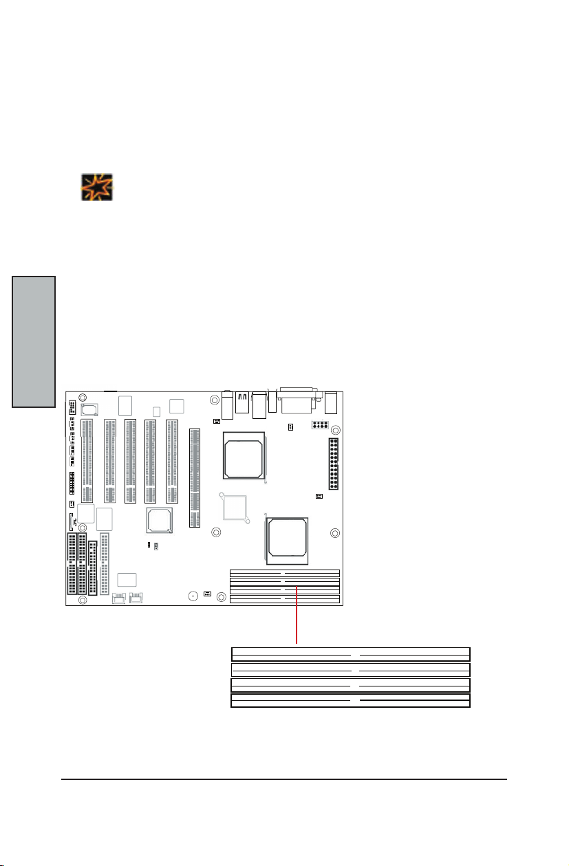
This MainBoard uses Dual Inline Memory Modules (DIMM). Two 4-DIMM socket memory
banks are available, one memory bank for each CPU socket. The DIMM sockets
accommodate 184-pin PC2100/PC2700 (DDR266/DDR333) and Double Data Rate (DDR)
memory modules in 128MB, 256MB, 512MB, 1GB and 2GB size combinations. Total
installed memory size is between a minimum of 128MB to a maximum of 8GB.
This section outlines how to install Registered PC2100/PC2700 DDR DIMMs into the
MainBoard.
INSTALLING MEMORY
IMPORTANT
* The MainBoard has strict memory and timing requirements. Before buying DDR
(Double Data Rate) DIMMs for use with the MainBoard, it is recommended that
you consult your local reseller for the best and most compatible memory to use.
* This MainBoard only supports Registered PC2100/PC2700 (DDR266/DDR333)
compliant modules.
Memory Installation Procedures
Memory
Bank
1. Locate the Memory Bank on the MainBoard, where you will be installing the
DIMMs.
A1
B1
A2
B2
Page 15
C-11
Hardware Install
Hardware
Install
Installing Memory continued...
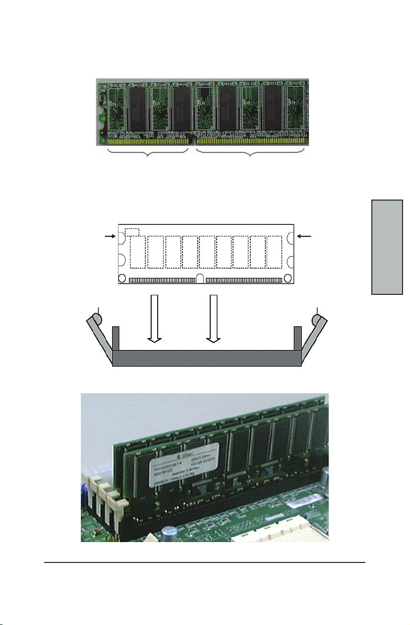
2. Make sure the DIMM’s pins are facing down, and check that the pin
arrangement on the memory module resembles the one pictured below.
80 pins
3. Insert the module into the DIMM socket and press down evenly on both ends
rmly until the DIMM module is securely in place. (The tabs of the DIMM socket
will close-up to hold the DIMM in place when the DIMM is properly installed on
the socket’s bottom.)
Notch Notch
Release Tab
4. Repeat step 1 to step 3 for all additional DIMM modules.
The notch
hole should
line up with
the notch on
the slot
DIMM Slot B1
DIMM Slot A1
104 pins
Release Tab
Page 16
MainBoard Manual
C-12
Hardware
Install
The AMD Opteron processors have very specic memory module requirements, and due to
the design of the MainBoard, there are certain congurations of memory that work best to
make the most effective use of the memory bandwidth.
The AMD Opteron features 128-bit DDR memory channels. DDR Memory Modules are only
64-bit. In order to benet from the full bandwidth, you should always install the DIMMs in
pairs. The MainBoard is designed to pair up DIMM slots A1/B1 and slots A2/B2 for the 128bit pathway.
The DIMM memory banks are shared over the dual CPU sockets. It is possible to operate a
system with two CPUs and only a pair of DIMMs in the memory bank.
The Opteron does support 64-bit only operation, but due to the design of the DIMM banks,
the single DIMM must be inserted in either DIMM slot A1 or DIMM slot A2 to function. The
system will NOT boot otherwise.
The following is our recommended DIMM installation path based on the number of DIMMS
being installed (Remember to check that the DIMMS are 2.5V Registered ECC DDR PC2100/
PC2700/DDR266/DDR333 DIMMs and that they appear on in Appendix A: Recommended
Memory Modules:
IMPORTANT
* The Opteron features a 128-bit wide DDR memory interface. To take advantage
of the 128-bit interface, you must install DIMMs in pairs of two (2). DIMM slots A1
and B1 are paired, and slots A2 and B2 are paired. If you are only installing two
DIMMS into a Memory Bank, it is recommended that you install them in slots A1
and B1 to get the full bandwidth.
* To ensure compatibility, only use DIMM pairs of the same exact type and size
and made by the same company. Refer to “Appendix A: Recommended Memory
Modules” for a list of supported DIMMS.
RECOMMENDED MEMORY CONFIGURATIONS
If you have... You should install them in...
1 DIMM Slot A1 or slot A2
2 DIMMs Slots A1/B1 OR Slots A2/B2
4 DIMMs Slots A1,B1,A2,B2
(Note: this conguration only provides 64-bit memory access)
Page 17

C-13
Hardware Install
Hardware
Install
INSTALLING THE PROCESSOR AND HEATSINK
The MainBoard accommodates AMD® Opteron micro-PGA Socket 940 processors and
a HyperTransport bandwidth of 6.4 GB/s. You must rst insert a CPU into CPU socket 1
(CPU1) before installing one in CPU socket 2 (CPU2).
Processor (CPU) Installation
This section outlines how to install a CPU into the MainBoard
1. Locate Pin 1 on the CPU socket and Pin 1 on the CPU itself.
2. Lift up the lever on the CPU Socket 940. Then line up Pin 1 on the CPU with the
Pin 1 marking on the socket before inserting the CPU into the Socket 940. Check
that the CPU is ush in the socket, and lower the lever to lock the CPU in place.
Pin1
3. Apply Thermal Compound (Thermal grease) to the top of the CPU.
4. Mount the Heatsink on top of the installed CPU by attaching it to the
motherboard with the included screws (rst on one side, then the other).
Pin 1 of
CPU is
lined up
with Pin1
of Socket.
Page 18
MainBoard Manual
C-14
Hardware
Install
Installing the Processor and Heatsink continued...
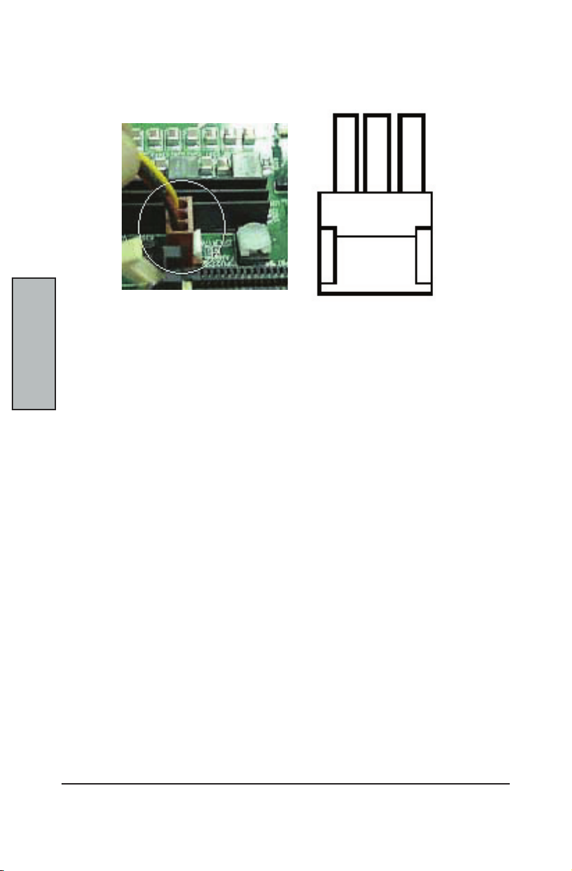
5. Connect the 3-wire fan cable to the CPU_Fan1 connector on the motherboard.
Black Red Yellow
GND
6. Repeat steps 1 thru 5 to install a second CPU (CPU2)
12V
Sensor
Page 19
C-15
Hardware Install
Hardware
Install
THE AGP PRO SLOT
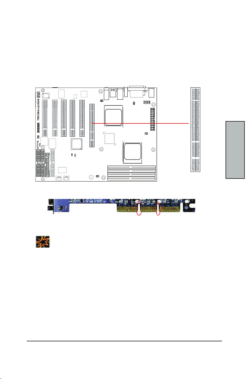
The MainBoard does not feature an integrated video solution. Therefore, you will need to
install a video card to use the MainBoard. The Accelerated Graphics Port Pro (AGP Pro) slot
is specically designed to support a new generation of AGP graphics cards with ultra-high
memory bandwidths (up to 8x).
This mainboard supports 4x/8x (1.5V) and 3.3V AGP video cards. The MainBoard will
automatically supply extra voltages as necessary to adapt to the installed AGP card.
8x AGP slot
AGP 2x
Notch
IMPORTANT
AGP 4x/8x
Notch
* Both 1.5V and 3.3V AGP cards are supported by this 8x AGP Pro slot. Refer to
the documentation that came with your AGP card for more information on Card
Settings..
Page 20
MainBoard Manual
C-16
Hardware
Install
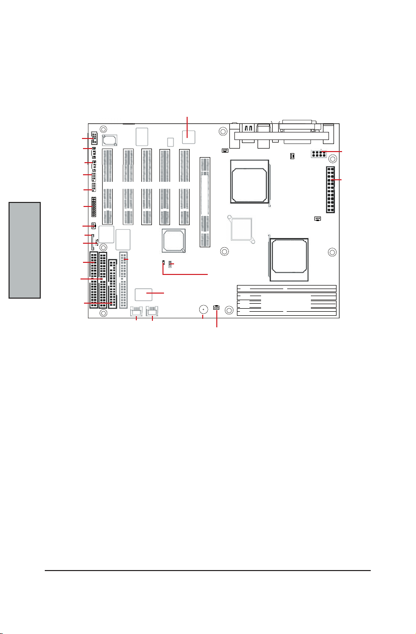
MAP OF MAINBOARD CABLE CONNECTORS
The following map of the MainBoard illustrates the location of all the connectors on the
MainBoard. Use this map to aide you in connecting devices to your MainBoard.
BroadCom
(Optional)
Front Panel
CMOS Battery
Secondary
F_Audio
CD_In
AUX_In
USB 2.0
Header
IEEE 1394
Header
Switches
Sys_Fan3
Wake_ON
LAN
IDE
Primary
IDE
Floppy
Five (5) 32-bit/33 MHz PCI slots
VIA
VT6307S
(Optional)
VIA
VT6202L
Parallel IDE
for Promise
Chipset
(Optional)
Port1 Por t2
Serial-ATA
Connectors
(Optional)
AMD
8111
HyperT
Promise
S-ATA/RAID
(Optional)
Clear CMOS
8x AGP Slot2
Speaker
Sys_Fan2
Sys_Fan1
Intruder
Alert
AMD
Opteron
Socket 940
(CPU2)
AMD
8151
AGP
A1
B1
A2
B2
I/O Port Array
CPU_Fan2
AMD
Opteron
Socket 940
(CPU1)
Memory Bank
ECC DDR DIMMs
CPU_Fan1
8-pin,12V
Power
24-Pin
Power
Page 21
C-17
Hardware Install
Hardware
Install
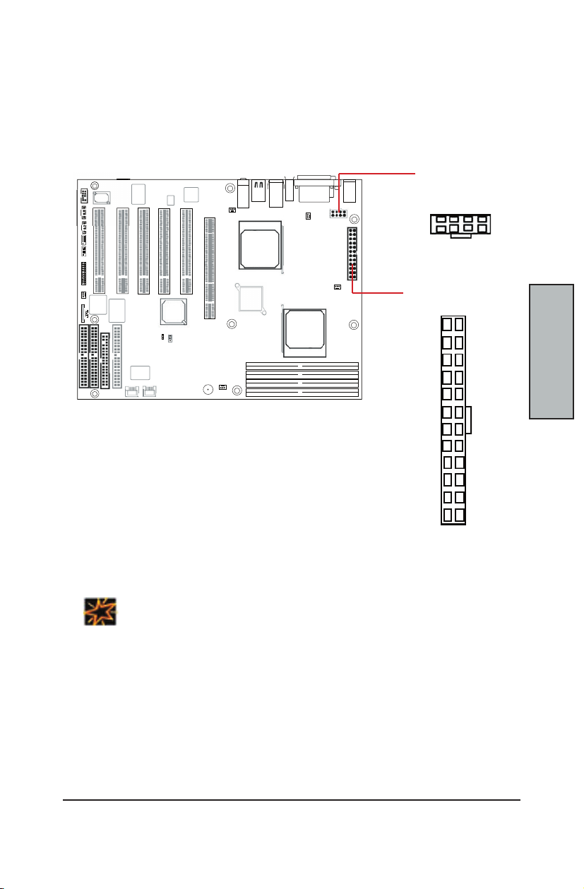
ATX POWER CONNECTORS
ATX 24-pin connectors connect the MainBoard to the ATX power supply. Find the proper
orientation of the connectors and push down rmly to make sure that the pins are aligned
(the connector will only insert properly when properly aligned). The 8-pin connector is a
dedicated power connector to supply power for the CPUs. For Wake on LAN support, the
5-volt Stand-by lead (+5VSB) from the ATX power supply must supply at least 2A.
8-pin Power Supply
Connector (+12V)
GND
GND
GND
GND
+12V
+12V
+12V
+12V
24-pin Power Supply
Connector
+3.3V
+12V
+12V
5VSB
PWR_OK
COM
+5V
COM
+5V
COM
+3.3V
+3.3V
COM
+5V
+5V
+5V
Reserved
COM
COM
COM
PS_ON
COM
-12V
+3.3V
It is recommended that you use an ATX Power Supply that complies with the Intel ATX 2.03
IMPORTANT
specication.
Page 22
MainBoard Manual
C-18
Hardware
Install
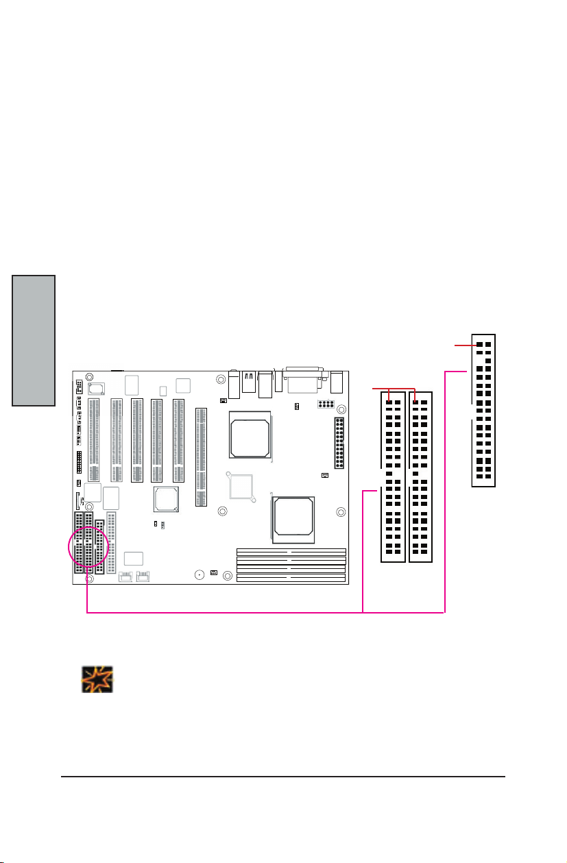
This 34-pin connector supports the standard oppy disk drive ribbon cable. Connect the
single connector end to the MainBoard. Then, plug the other end of the ribbon into the
oppy drive. Make sure you align the Pin 1 on the connector with the Pin 1 alignments on
the MainBoard and the oppy drive.
The two 40-pin IDE connectors (primary and secondary channels) support 80-conductor
IDE ribbon cables. Connect the single connector end to the MainBoard. Then, connect
the two connectors at the other end to your IDE device(s). If you connect two hard disks
to the same cable, you must set the second drive as a Slave through its jumpers settings.
Refer to the IDE device's documentation for the specic jumper settings. (Pin 20 is removed
to prevent the connector from being insertied in the wrong orientation when using ribbon
cables with pin 20 plugged in). The BIOS supports Ultra DMA 33/66/100/133.
FLOPPY DISK DRIVE CONNECTOR
PRIMARY IDE CONNECTORS
Pin1
34-pin Floppy
Connector
Pin1
40-pin IDE
Connectors
IDE_S IDE_P
IMPORTANT
Ribbon cables should always be connected with the red stripe on the Pin 1 side of the
connector. IDE ribbon cables must be less than 46 cm (18 inches) long, with the second drive
connector no more than 15 cm (6 inches) away from the rst connector.
Page 23
C-19
Hardware Install
Hardware
Install
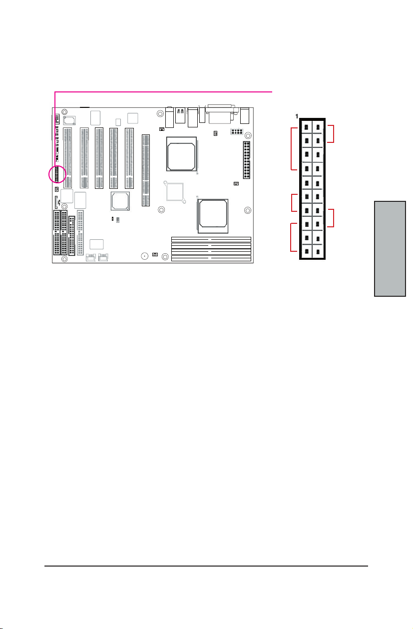
FRONT PANEL SWITCHES
The front panel switches header connects the front control panel buttons and LEDs to the
MainBoard.
Front Panel
Switch Headers
Reset
Speaker
Power
Switch
0
Power
LED
+
0
HDD_
LED
+
Reset Switch (2-pin RST)
This 2-pin connector connects to the chassis-mounted reset switch for rebooting your
computer without turning your power switch off and on. This is a preferred method of
rebooting your system to prolong the life of your system’s power supply.
Hard Disk Activity LED (2-pin HDD_LED)
This connector supplies power to the chassis's HDD/IDE activity LED. Read and Write
activity by devices connected to the Primary or Secondary IDE connectors will cause the
front panel LED to light up.
Speaker Connector (4-pin SPEAKER)
There is one jumper over pin1 and pin2 (default setting) for the internal buzzer. If you want
to use the external case-mounted speaker instead of the internal buzzer, remove the jumper
and connect the speaker wire to the 4-pin connector.
ATX Power Switch / Soft Power Switch (2-pin PWR_SW)
A momentary switch connected to this 2-pin connector controls the system power. Pressing
the button once will switch the system between ON and SLEEP mode. The system power
LED shows the status of the system’s power.
System Power LED (3-pin PWR_LED)
This 3-pin connector connects to the chassis-mounted system power LED, which lights up
when the system is powered on.
Page 24

MainBoard Manual
C-20
Hardware
Install
FRONT/BACK/CPU/AUX FAN CONNECTORS
There are nine 3-pin fan connectors in the MainBoard motherboard. Two fans are used for
CPU0 and CPU1; seven are for auxiliary power. These connectors support cooling fans
of 500mA (6W) or less. Depending on the fan manufacturer, the wiring and plug may be
different. Connect the fan’s plug to the MainBoard with respect to the polarity of the fan
connector.
3-pin Fan Connector
The CPU and/or motherboard will overheat if there is not enough airow across the CPU and
onboard heatsink. Damage may occur to the motherboard and/or the CPU fan if these pins
are incorrectly used. These are NOT jumpers, do NOT place jumper caps over these pins.
WARNING
Sensor +12V GND
Sys_Fan1
CPU_Fan2
CPU_Fan1
Sys_Fan3
Sys_Fan2
NOTE
* The “Rotation” signal can only be used with fans specially designed for the
rotation signal.
* Only fans connected to CPU _Fan1 and CPU_Fan2 are monitored by the BIOS.
Page 25

C-21
Hardware Install
Hardware
Install
REAR PANEL I/O PORTS
This is an illustration of the MainBoard rear I/O port array
COM1
Parallel Port
IEEE
1394
(Optional)
GigE LAN
USB 1.1
Ports (2)
USB 2.0
Ports (2)
Audio Jacks:
Line-In
Spk-Out
Mic-In
PS/2 Mouse
PS/2 KBD
PS/2 Mouse Connector (6-pin Female)
The system will direct IRQ12 to the PS/2 mouse if one is detected. If no mouse is detected,
IRQ12 will be free for expansion cards to use.
PS/2 Keyboard Connector (6-pin Female)
This connection is for standard keyboards using a PS/2 (mini DIN) plug. This connector will
not accept standard AT size (large DIN) keyboard plugs. You may need a DIN to mini DIN
adapter for standard AT keyboards.
Universal Serial Bus Ports (4-pin Female)
Two (2) onboard external USB 1.1 ports are available for connecting USB devices.
Depending on your MainBoard model, you may have two (2) onboard USB 2.0 ports
available. Refer to USB 2.0 Ports & Header for more information.
IEEE 1394 / FireWire Connector (6-pin Male) (Optional)
Depending on your MainBoard model, you may have one (1) onboard IEEE 1394 connector
port for connecting FireWire devices. Refer to IEEE 1394 Ports & Header for more
information.
Serial Port (COM1) Connector (9-pin Male)
The COM1 serial port can be used for pointing devices or other serial devices. See BIOS
for more on serial port setup.
Parallel Printer Connector (25-pin Female)
You can enable the parallel port and choose an IRQ through the BIOS. You can choose
between ECP and EPP support through the BIOS setup.
Onboard LAN Port (RJ-45)
This MainBoard uses the Broadcom BCM5702 Gigabit Ethernet Controller. The controller
consists of both the Media Access Controller (MAC) and Mbps Physical Layer (PHY)
interface. Refer to the “Onboard LAN User Guide” for further information.
Audio Jacks (Phone Jacks)
The interface with the onboard RealTek ALC-650. It has 3 phone jacks for Speaker-Out,
Microphone In, and Line-In.
Page 26

MainBoard Manual
C-22
Hardware
Install
The MainBoard also contains connectors for adding additional ports and devices to the
MainBoard.
In order to use the front audio connector, you need to have a chassis that has a frontaudio connector. Make sure that the pin assignment of the cables are the same as the pin
assignment on the MainBoard
* If you want use the rear audio connectors, keep the jumpers installed. (Default setting)
* If you want use front audio connectors, remove the jumpers and connect the Front Audio
Connector Cable.
There are both CD-In and Aux-In 4-pin connectors to connect your internal sound devices
to the Sound Card. See Audio for setup information.
ADDITIONAL I/O CONNECTORS
Front Audio Jumpers and Headers (F_Audio)
1 2
9 10
CD_In & Aux_In Audio Inputs (4-pin)
4-pin Onboard
Audio Header
1
F_Audio Pin Assignments
Pin Desc. Pin Desc.
1 Mic1 2 GND
3 Mic2 4 Power
5 Front Audio R 6 Rear Audio R
7 Reserved
9 Front Audio L 10 Rear Audio L
Audio Pin Assignments
Pin Description
1 Audio- L
2 Ground
3 Ground
4 Audio - R
F_Audio Header
CD-In for Sound Card
Aux-In for Sound Card
Wake On LAN
Case Intruder
Case Intruder (2-pin)
This connector enables the Case Open / Intruder Alert item in the Hardware Monitor.
Connect this header to the appropriate cable in the system chassis to enable.
Page 27

C-23
Hardware Install
Hardware
Install
Additional I/O Connectors continued...
Wake On LAN (3-pin)
This connector enables an expansion LAN card to boot up and control the system. The
connector powers on the system when a WakeUp pakcet or signal is received through the
LAN card. Use the Wake_ON_LAN cable to connect the MainBoard to the expansion card.
1
WOL Pin Assignments
Pin Description
1 PME
2 Ground
3 +5 V StandBy
INSTALLING EXPANSION CARDS
This outlines the procedure for adding expansion cards to your MainBoard. Remember to
read the documentation for your expansion cards and make the necessary hardware and
software setting changes (i.e. jumper settings).
The MainBoard features ve (5) PCI-32 (32-bit, 33MHz) slots to accomodate PCI expansion
cards.
1. Remove the bracket plate on the slot you intend to use. Keep the bracket for
possible future use.
2. Insert the PCI card into the correct slot on the MainBoard, pushing down with
your thumbs evenly on both sides of the card.
3. Secure the card on the slot with the screw you removed above.
Completely power OFF your power supply when adding or removing any expansion cards
WARNING
or other system components. Failure to do so may cause severe damage to both your
MainBoard and expansion cards.
Page 28
MainBoard Manual
C-24
Hardware
Install
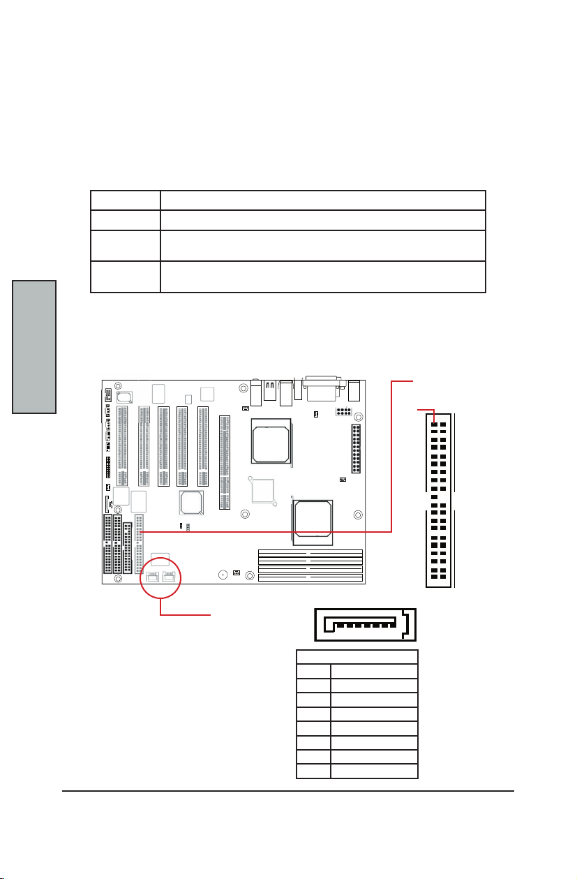
The Serial version of this MainBoard is equipped with an integrated Promise PDC20378
Serial ATA chipset. This chipset supports up to 4 IDE devices at transfer rates of up to
150MB/s.
The Promise Chipset also supports RAID congurations. RAID stands for "Redundant
Array of Independent Devices" and provides different levels of safety, redundancy and
performance. This chipset supports RAID 0, 1, and 10, which are dened as follows:
The Serial version of this MainBoard features two (2) Serial ATA ports and a Blue 40-pin
connector for 2 parallel IDE devices. Refer to the documentation that came with the drives
for more information about settings and installation.
PROMISE CHIPSET AND SERIAL ATA (OPTIONAL)
RAID Type Description
RAID 0 Striping: high performance, designed ot connect multiple drives to act as one
RAID 1 Mirroring: writes data to two drives at once in case one drive fails, the other
one will be a complete replica and can continue on. Full fail-over
RAID 10 a combination of RAID 0 and 1: over 4 drives, The drives are split in half and
striped together, and the 2 new striped drives are then mirrored.
40-pin IDE
Connectors
Pin1
7-pin Serial ATA
Ports (2x)
Serial ATA Pin Assignments
Pin Description
1 GND
2 TXP
3 TXN
4 GND
5 RXN
6 RXP
7 GND
17
Page 29

C-25
Hardware Install
Hardware
Install
INTEGRATED AUDIO
This MainBoard features an integrated RealTek ALC-650 audio chip. It is a professional 6channel processor using the AC '97 CODEC. Due to that, there are a few extra connectors
dedicated to the audio capabilities of this chip.
There is a Front Audio Connector with Jumpers. There is a bar of phone jacks in the back for
audio output that can be used as normal (Speaker Out, Mic In, Line In) or you can modify the
Windows XP conguration to get 6 speaker sound using the same 3 phone jacks.
Page 30

MainBoard Manual
C-26
Hardware
Install
The Serial Version of this MainBoard features the VIA VT6202L chip integrated into the
board. This chip supports four (4) USB 2.0 ports. USB 2.0 supports transfer rates of up to
480MB/s. Two show up on the on-board I/O array, and a header completes the last two (2)
for external installation.
The Serial Version of this MainBoard features an integrated VIA VT6307S chip which
supports two (2) IEEE 1394 (Firewire) ports. IEEE 1394 (FireWire) supports transfer rates of
up to 400MB/s. One port is installed on the on-board I/O array, and a header completes the
last port for external installation.
USB 2.0 PORTS AND HEADER
5-pin Onboard
USB Header
1
USB Pin Assignments
Pin Description
1 VCC
2 Data 3 Data +
4 Ground
5 NC / Key
IEEE 1394 (FIREWIRE) PORTS AND HEADER (OPTIONAL)
9-pin Onboard
IEEE 1394 Header
1
IEEE 1394 Pin Assignments
Pin Desc. Pin Desc.
1 TPB+ 2 TPB3 GND 4 GND
5 TPA+ 6 TPA7 VCC 8 VCC
9 N/C
Page 31

C-27
Hardware Install
Hardware
Install
POWERING ON YOUR SYSTEM
Follow these instructions to power on the computer after you have installed the MainBoard
and all system devices.
1. Be sure that all switches are off (in some systems, Off is marked by “O”).
2. After double-checking all jumper settings and connections, close the system
chassis cover.
3. Connect the power cord to the power cord connector located on the power
supply at the back of your system chassis and plug the power cord into a power
outlet that is equipped with a surge protector.
4. Turn on your devices in the following order:
− Monitor
− External SCSI devices (starting with the last device on the chain)
− System power
For ATX power supplies, you need to switch On the power supply, then press
the ATX power switch on the front of the chassis the rst time you start up the
system.
5. The power LED on the front panel of the system case will light up. For ATX power
supplies, the system LED will light up when the ATX power switch is pressed.
The monitor LED may light up after the system’s LED if it complies with “Green”
standards or if it has a power standby feature. The system will rst run its
“power-on” tests. While the tests are running, additional messages will appear
on the screen. If you do not see anything on the screen within 30 seconds from
the time you turn on the power, the system may have failed a power-on test.
Re-check your jumper settings and connections. Contact your retailer/dealer for
assistance if everything else fail.
6. During power-on, hold down <F2> to enter BIOS setup. Follow the instructions in
BIOS for further setup information.
To Power OFF your system, You have to rst exit or shut down your operating system before
NOTE
switching OFF the power switch. In most operating systems with ATX power supplies,
the Advanced Power Management Interface (APMI) features will turn the computer off
automatically. In some ATX power supplies, you need to press the ATX power switch after
exiting or shutting down your operating system to turn off your system.
Page 32

MainBoard Manual
C-28
Hardware
Install
This Page is Intentionally Left Blank
Page 33

C-29
BIOS
This chapter discusses the PhoenixBIOS Setup program built into the ROM BIOS. The Setup
program allows users to modify the basic system conguration.
The BIOS is the Basic Input / Output System used in all IBM® PC, XT™, AT®, and PS/2®
compatible computers. The PhoenixBIOS ash chip stores the system parameters, such
as type of disk drives, video displays, etc. in the CMOS. When the computer is turned
off, a back-up battery provides power to the BIOS ash chip, enabling it to retain system
parameters. Each time the computer is powered-on the computer is congured with the
values stored in the BIOS ROM by the system BIOS, which gains control at boot-up.
The PhoenixBIOS installed in your computer system’s ROM (Read Only Memory) is a
custom version of an industry standard BIOS. The BIOS provides critical low-level support
for standard devices such as disk drives and serial and parallel ports.
This section is divided up as follows:
Starting the BIOS Setup C-30
Using the BIOS Setup Utility C-30
BIOS Setup Main Menu C-32
Master and Slave SubMenus C-33
Advanced Menu C-35
HyperTransport Conguration SubMenu C-36
8x AGP Control Options SubMenu C-38
Chipset Conguration SubMenu C-40
Keyboard Conguration SubMenu C-42
I/O Device Conguration SubMenu C-43
Console ReDirection SubMenu C-45
PCI Devices SubMenu C-46
Security Menu C-48
Passwords C-48
Setting and Using Passwords C-49
Power Menu C-50
Boot Menu C-52
Server Menu C-53
Hardware Monitor SubMenu C-54
Exit Menu C-55
Phoenix Boot Utilities C-57
Using Phoenix QuietBoot C-57
Phoenix MultiBoot C-58
BIOS Flash Upgrade Utility C-59
Create a Crisis Recovery Diskette C-59
Updating the Crisis Recovery Diskette C-60
Executing Phoenix Phlash C-60
Disabling Memory Managers C-61
BIOS
Setup
BIOS Setup
Page 34
MainBoard Manual
C-30
BIOS
Setup
STARTING THE BIOS SETUP
The PhoenixBIOS is immediately activated every time you power on the system. The BIOS
reads the system information contained in the CMOS and begins the process of checking
the system and conguring it. After conguring the system, the BIOS will follow the Boot
Order to seek out an operating system. The BIOS then turns control of the system over to
the operating system.
The CMOS information that determines the system parameters may be changed by entering
the BIOS Setup utility.
1. Power on the System.
Note: Normally, the only visible POST (Power On Self Test) routine is the memory test.
2. As the memory is being tested, you can access the BIOS Setup Utility by
pressing the <F2> key when “Press F2 to enter SETUP” appears briey at the
bottom of the screen.
From the main menu of the BIOS Setup Utility, you can access the other setup screens, such
as the Security and Power menus.
USING THE BIOS SETUP UTILITY
Navigating through the BIOS Setup Utility is straight forward. Use the arrow keys to highlight
items, press <Enter> to select items in menus, and press <Esc> to quit. The following table
provides more details about how to navigate in the Setup program using the keyboard.
Up ArrowKey Move to the previous item
Down Arrow Key Move to the next item
Left Arrow Key Move to the previous menu
Right Arrow Key Move to the next menu
<Esc> key or
<Alt-X>
<Enter> Key Select the highlighted item. When available, a pop-up list will display for you to
<PgUp> Key Previous page on Scrollable menus or Jump to the rst interactive item listed
<PgDn> Key Next page on Scrollable menus or Jump to the last interactive item listed
+ Key Increase the numeric value or make a change
– Key Decrease the numeric value or make a change
<F1> Key or
<Alt-H>
<F5> Key
<F6> Key or <Space> Select next higher value for eld
<F7> Key Load Optimal Defaults this page
<F9> Key
<F10> Key
<Tab> or <Shift-Tab> Select Next / Previous Field in the menu
<Home> or <End> Move cursor to top or bottom of window.
<PgUp> or <PgDn> Move cursor to next / previous page in scrollable menus.
<Alt-R> Refresh screen.
In the Submenu: Exit the submenu.
In the BIOS main menu: Jump to the Exit Menu
select the item value or select a submenu
General Help on Setup navigation keys.
Press <F1> key to view a small help window that describes the appropriate keys
to use and the possible options for the highlighted item. To exit the Help Window,
press <ESC> key or press the <F1> key again.
Select next lower value for eld
Load Conguration
Save Conguration and exit the BIOS Setup Utility
Page 35

C-31
BIOS Setup
BIOS
Setup
Navigating the Menus
Use the arrow keys to move between the options. The scroll bar on the right of any window
indicates that there is more than one page of information in the window. Use <PgUp> and
<PgDn> to navigate between the pages. Pressing <Home> and <End> displays the rst
and last page. Press <Esc> to exit the current window.
The Field Help Window
The help panel/window on the right side of each menu displays the help text for the currently
selected eld. It updates as you move through each eld.
Activating SubMenus
Use the arrow keys to move the cursor over the desired submenu option. Press <Enter> and
the submenu will be accessed. A » symbol designates all submenus.
Saving Values
To Save the values you have just set, move the cursor to the Exit Menu. The Save Values
option saves all values currently displayed in the menus.
The BIOS does NOT automatically save values that you have modied. If you do not save
IMPORTANT
your values before you exit the BIOS Setup Utility, all your changes will be lost.
If after making and saving system changes with the BIOS Setup Utility, you discover that your
computer is no longer able to boot, the PhoenixBIOS supports an override, which will reset
your system to the Failsafe defaults. If that fails, it is possible to manually clear the present
CMOS information through the "Clear CMOS Header" on the motherboard (Refer to Jumper
Settings for more information).
The best advice is to ONLY alter settings which you thoroughly understand. The default
settings have been carefully chosen by PhoenixBIOS to provide the maximum system
performance and reliability. Even a slight change to the chipset setup may cause potential
and unpredictable failure to the system.
Page 36
MainBoard Manual
C-32
BIOS
Setup
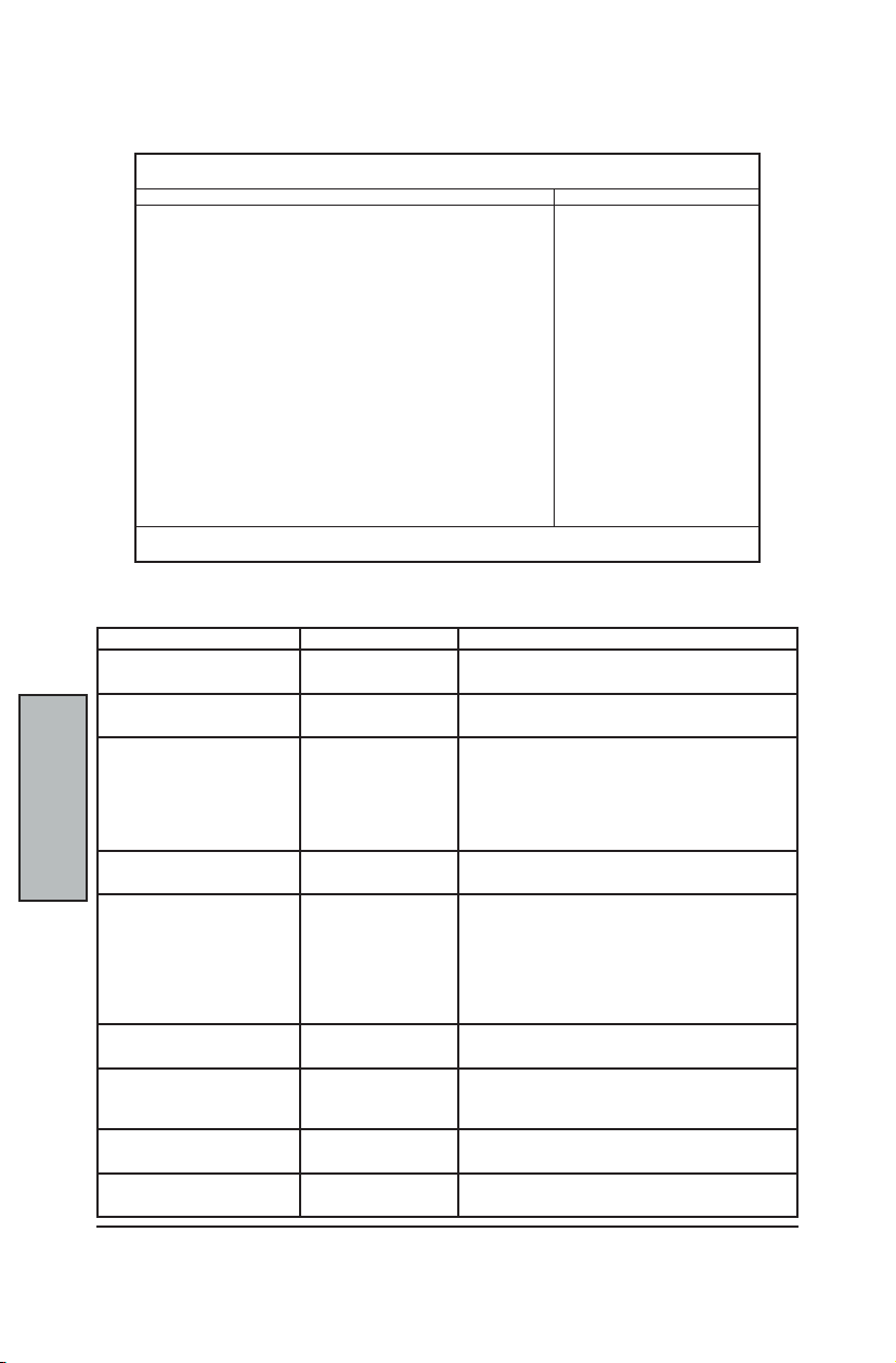
This is the rst screen that is displayed when you enter the BIOS Setup Utility.
You can make these modications on the Main Menu itself. Select the Submenus to modify
those settings.
* A large disk is one that has:
- more than 1024 cylinders,
- more than 16 heads, or
- more than 63 tracks per sector
BIOS SETUP MAIN MENU
Main Advanced Security Power Boot Server Exit
System Time: [16:19:20]
System Date: [03/02/2003]
Legacy Diskette A: [1.44/1.25 MB 3”]
Legacy Diskette B: [Disabled]
»
Primary Master 6449 MB
»
Primary Slave None
»
Secondary Master CD-ROM
»
Secondary Slave None
HDD Post Write Buffer: [Disabled]
Large Disk Access Mode: [DOS]
Boot Summary Screen: [Disabled]
Extended Memory Testing: [Just zero it]
System Memory: 640 KB
Extended Memory: 31744 KB
F1 Help ^v Select Item –/+ Change Values F9 Setup Defaults
ESC Exit <> Select Menu Enter Select » Submenu F10 Save and Exit
Feature Options Description
System Time HH:MM:SS Set the system time.
System Date MM/DD/YYYY Set the system date.
Diskette A
Diskette B
HDD Post Write Buffer Disabled
Large Disk Access Mode
Boot Summary Screen Disabled
Extended Memory Testing Enabled
System Memory N/A Displays amount of conventional memory detected
Extended Memory N/A Displays the amount of extended memory detected
PhoenixBIOS Setup Utility
<Tab>, <Shift-Tab> or <Enter> selects eld
<Tab>, <Shift-Tab> or <Enter> selects eld
Disabled
360 KB, 5 ”
1.2 MB, 5 ”
720 KB, 3 ”
Selects oppy-disk type installed in your system.
Note that 1.25 MB 3” references a 1024 byte/
sector Japanesemedia format. The 1.25 MB 3”
diskette requires a Mode 3 oppy disk drive.
1.44/1.25 MB, 3 ”
2.88 MB, 3 ”
Enable/disable HDD post write buffer support.
Enabled
Other
DOS
Enable this item for better performance.
Unix, Novell Netware or other operating systems,
select "Other".
* If you are installing new software and the drive
fails, change this selection and try again. Different
operating systems require different representations
of drive geometries.
Display system conguration on Boot.
Enabled
Determines which type of tests will be performed on
Just zero it
the Extended memory (above 1M)
Disabled
during boot up.
during boot up.
Item Specic Help
<Tab>, <Shift-Tab>,
or <Enter> selects
eld
Page 37

C-33
BIOS Setup
BIOS
Setup
MASTER AND SLAVE SUBMENUS
The Master and Slave submenus accessed from the Main Menu controls Hard-Disk Drives,
Removable-Disk Drives (such as Zip Drives) and CD-ROM Drives.
The PhoenixBIOS 4.0 supports up to two IDE disk controllers. They are referred to as primary
and secondary controllers. Each controller supports one master drive and one slave drive.
When designing your system, it is recommended that you install your IDE devices on the
two controllers as follows (refer to your IDE device's documentation on how to set them as
Master or Slave) :
* If you have 1 drive: 1 Primary Master
* If you have 2 drives: 1 Primary Master, 1 Primary Slave OR
1 Primary Master, 1 Secondary Master
* If you have 3 drives: 2 Masters, 1 Slave
* If you have 4 drives: 2 Masters, 2 Slaves
There is one IDE connector for each controller on your machine, normally labeled “Primary
IDE” and “Secondary IDE.” There are usually two connectors on each IDE ribbon cable.
When the ribbon cable is attached to the system's IDE connector and connected to two
drives, the device on the end of the cable is the Master. If you set your drive to "Cable
Select", then the drive may show up as either a master or a slave depending on which
connector it is attached and what other device is connected to the same ribbon cable.
In the Main Menu, it displays the results of Autotyping—information each drive provides
about its own parameters (e.g., cylinders, heads, and sectors)—and the drives appear how
they are arranged in the system as Primary or Secondary and Masters or Slaves.
Select one of the Master or Slave drive submenus if you need to change your drive settings.
Pressing <Enter> on the selected drive displays the following submenu:
Main
Type: [Auto]
Cylinders: [13328]
Heads: [ 15]
Sectors: [ 63]
Maximum Capacity: 6449 MB
Total Sectors: [0]
Maximum Capacity: [0MB]
Multi Sector Transfer: [16 Sectors]
LBA Mode Control: [Enabled]
32-bit I/O: [Enabled]
Transfer Mode: [Fast PIO 4]
Ultra DMA Mode: [Enabled]
F1 Help ^v Select Item –/+ Change Values F9 Setup Defaults
ESC Exit <> Select Menu Enter Select » Submenu F10 Save and Exit
PhoenixBIOS Setup Utility
Primary Master Item Specic Help
User = You enter
CHS Format
LBA Format
parameters of harddisk Drive installed
at this connection.
Auto = Auto-Types
hard-disk drive
installed here.
1-39 = You select
pre-determined type
of hard-disk drive
installed here.
CD-ROM = a CD-ROM
drive is installed
here
ATAPI Removable =
removable disk drive
is installed here
Page 38

MainBoard Manual
C-34
BIOS
Setup
Use the following chart to congure your Master/Slave devices:
Max. Capacity 0 ~ current limit Displays total disk capacity. Not Selectable
Total Sectors 1 to 63 Number of sectors per track.
Max. Capacity 0 ~ current limit Displays total disk capacity. Not Selectable
Transfer Mode Standard
Master/Slave SubMenu continued...
Feature Options Description
Type None
CHS Format * Selectable ONLY when Type = [User]
Cylinders 1 to 65,536 Number of cylinders.
Heads 1 to 16 Number of read/write heads.
Sectors 1 to 63 Number of sectors per track.
LBA Format * Selectable ONLY when Type = [User]
Multi-Sector
Transfers
LBA Mode
Control
32-Bit I/O Disabled
Ultra DMA
Mode
1 to 39
User
Auto
IDE Removable
CD-ROM
ATAPI Removable
Disabled
2 sectors
4 sectors
8 sectors
16 sectors
Disabled
Enabled
Enabled
Fast PIO 1 ~ 4
FPIO 3 / DMA 1
FPIO 4 / DMA 2
Disabled
Mode 0 ~ 6
None = Either that Autotyping is not able to supply the drive type OR the
end user has selected "None", disabling any drive that may be installed.
User = The end-user supplies the hard-disk/device information.
Auto = Autotyping, the drive itself supplies the drive information.
IDE Removable = Removable read-and-write media drive (e.g., IDE Zip
drive).
CD-ROM = Readable CD-ROM drive.
ATAPI Removable =Drive that Reads-and-writes to a media (e.g., LS120,
USB Floppy, USB Zip).
(You do NOT need to set Landing Zone and Write Precomp for IDE drives)
Specify the number of sectors per block for multiple sector transfers.
"MAX" refers to the size the disk returns when queried.
Enabling LBA causes Logical Block Addressing to be used in place of
Cylinders, Heads, & Sectors.
This setting Enables/Disables 32-bit IDE Data Transfers
Select the method for moving data to / from the drive.
Auto-Type the drive to select the optimum transfer mode.
Selects the Ultra DMA mode used for moving data to / from the drive.
Auto-Type the drive to select the optimum transfer mode.
Some older drives, do not use Autotyping and require that the end-user select a pre-dened
xed-disk-type value or specifying the drive parameters separately with the "User" type
option selected. You can nd the correct parameters for hard-disk drives in the device's
manual or written on the casing of the drive itself.
NOTE
Once you have established correct parameters for your drive, write them down and store
them in a safe place in case these values are lost in the CMOS or if autotyping fails. If these
parameters are not correctly entered in CMOS, you will NOT be able to access the data on
your drive.
WARNING
Incorrect settings can cause your system to malfunction. To correct mistakes, return to the
Setup and rst restore the Setup Defaults with <F9>. Then, enter the correct drive info.
Page 39
C-35
BIOS Setup
BIOS
Setup
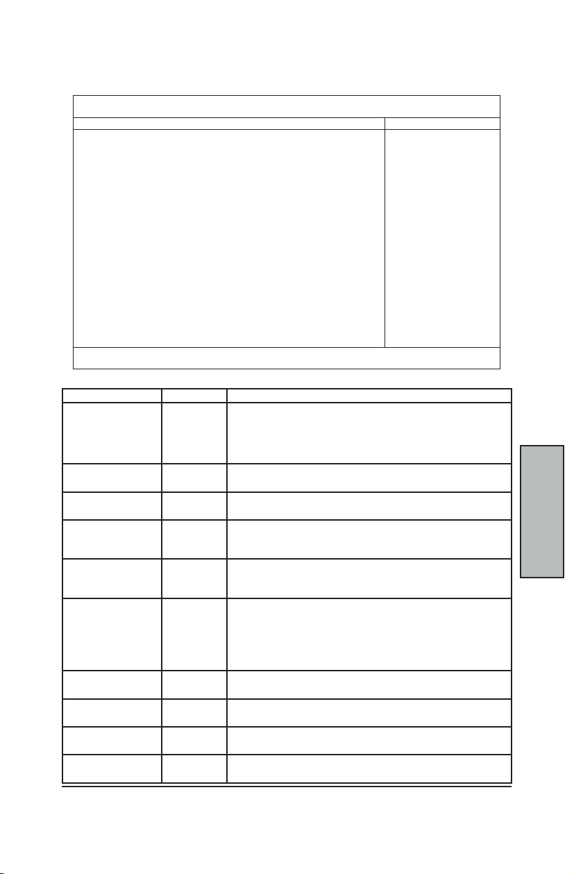
ADVANCED MENU
The Advanced menu selection in the menu bar on top of the screen displays the following:
Main Advanced Security Power Boot Server Exit
Installed O/S: [Other]
Reset Conguration Data: [No]
»
HyperTransport Conguration
»
8x AGP Control Options
USB Host Controller: [Enable]
USB BIOS Legacy Support: [Enable]
4GB Memory Hole Adjust: [Auto]
4GB Memory Hole Size: [64 MB]
Multiprocessor Specication: [1.4]
Use PCI Interrupt Entries in MP Table: [Yes]
»
Chipset Conguration
»
Keyboard Conguration
»
I/O Device Conguration
QuickBoot Mode: [Enable]
Boot Diagnostic Screen: [Disable]
»
PCI Conguration
»
Console Redirection
F1 Help ^v Select Item –/+ Change Values F9 Setup Defaults
ESC Exit <> Select Menu Enter Select » Submenu F10 Save and Exit
Use this chart to help you congure your Advanced Menu:
Feature Options Description
Installed Operating
System
Reset Conguration
Data
USB Host Controller Disable
USB BIOS Legacy
Support
4GB Memory Hole
Adjust
4GB Memory Hole
Size
Multiprocessor
Specication
Use PCI Interrupt
Entries in MP Table
QuickBoot Mode Disable
Boot Diagnostic
Screen
PhoenixBIOS Setup Utility
Other
Win95
Select the operating system installed on your system which you will
use most commonly.
Win98
WinMe
Win2000
No
Yes
Select "Yes" if you want to clear the Extended System Conguration
Data (ESCD) area.
Enables or Disables the USB hardware.
Enable
Disable
Enable
(Disabled resources will be freed up for other uses)
Enables or Disables support for USB Keyboards and Mice.
(Enable for use with a non-USB aware Operating System such as
DOS or UNIX)
Manual
Auto
Auto = Adjust the memory hole size automatically according to the
memory space used by PCI devices.
Manual = memory hole size is determined manually.
64 MB
4GB Memory Hole Size
128 MB
256 MB
512 MB
1 GB
2 GB
1.1
1.4
Yes
Congures the MultiProcessor Specication revision level. Some
Operating Systems will require 1.1 for compatibility reasons
Congures the MP Table with PCI Interrupt entries.
No
Allows the system to skip certain tests while booting. This will
Enable
Disable
decrease the time needed to boot the system.
Display the diagnostic screen during Boot.
Enable
Item Specic Help
Select the
operating system
installed on your
system which you
will use most
commonly.
Note: An
incorrect setting
can cause some
operating systems
to display
unexpected
behavior.
Page 40
MainBoard Manual
C-36
BIOS
Setup
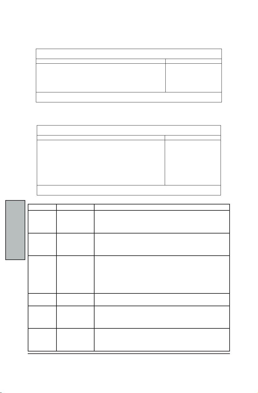
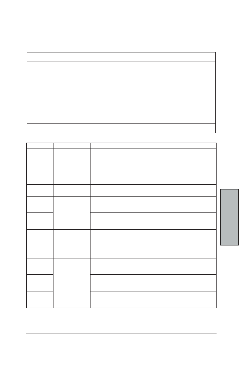
This screen is displayed when you select the " HyperTransport Conguration" SubMenu from
the Advanced Menu.
This screen is displayed when you select the "Lokar Side A" SubMenu from the
HyperTransport SubMenu.
Use this chart to help you congure your Lokar Side A SubMenu:
Lokar Side A
Lokar Side A
Lokar Side A
HYPERTRANSPORT CONFIGURATION SUBMENU
Advanced
»
Lokar Side A
»
Lokay Side B
F1 Help ^v Select Item –/+ Change Values F9 Setup Defaults
ESC Exit <> Select Menu Enter Select » Submenu F10 Save and Exit
HyperTransport Conguration Item Specic Help
Lokar Side A SubMenu
Advanced
Lokar Side A Width: [8-bit]
Lokar Side A Speed: [200 MHz]
Lokar Side A Pos Edge Comp: [CALCOMP]
Lokar Side A Neg Edge Comp: [CALCOMP]
Lokar Side A Impedence Comp: [CALCOMP]
F1 Help ^v Select Item –/+ Change Values F9 Setup Defaults
ESC Exit <> Select Menu Enter Select » Submenu F10 Save and Exit
Feature Options Description
Width
Speed
Lokar Side
A Pos Edge
Comp
DATA 0~31 Select the value to be used with the Auto-Compensation logic,
Lokar Side
A Neg Edge
Comp
Impedence
Comp
8-bit
16-bit
2-bit
4-bit
200 MHz
400 MHz
600 MHz
800 MHz
CALCOMP
DATA
CALCOMP + DATA
CALCOMP - DATA
CALCOMP
DATA
CALCOMP + DATA
CALCOMP - DATA
CALCOMP
DATA
CALCOMP + DATA
CALCOMP - DATA
PhoenixBIOS Setup Utility
HyperTransport
Link Conguration
and Compensation
Control.
PhoenixBIOS Setup Utility
Lokar Side A Item Specic Help
Transmitting
port’s width. The
width of receiving
port on the other
side of the link
is also controlled
by this value
Transmitting port's width.
The width of receiving port on the other side of the link is also controlled
by this value
The port's transmission frequency.
Transmitter rising edge (P) drive strength compensation mode.
Either apply CALCOMP directly, apply DATA directly, add DATA to
CALCOMP or subtract DATA from CALCOMP.
CALCOMP = a calculated value from the auto-compensation circuitry
Result clamped between 1 and 19.
Type in value, or use the <+> and <-> keys
Transmitter falling edge (N) drive strength compensation mode.
Result clamped between 1 and 19
Receiver impedence compensation
Result clamped between 0 and 31
Page 41
C-37
BIOS Setup
BIOS
Setup
HyperTransport Conguration SubMenu continued...
Lokar Side B SubMenu
This screen is displayed when you select the "Lokar Side B" SubMenu from the
HyperTransport SubMenu.
Advanced
Lokar Side B Pos Edge Comp: [CALCOMP]
Lokar Side B Neg Edge Comp: [CALCOMP]
Lokar Side B Impedence Comp: [CALCOMP]
Lokar Side B Width: [8-bit]
Lokar Side B Speed: [200 MHz]
Thor0 Port0 Tx Pos Mode: [CALCOMP]
Thor0 Port0 Tx Neg Mode: [CALCOMP]
Thor0 Port0 Rx Imp Mode: [CALCOMP]
F1 Help ^v Select Item –/+ Change Values F9 Setup Defaults
ESC Exit <> Select Menu Enter Select » Submenu F10 Save and Exit
Use this chart to help you congure your Lokar Side B SubMenu:
Feature Options Description
Lokar Side
B Pos Edge
Comp
DATA 0~31 Select the value to be used with the Auto-Compensation logic,
Lokar Side
B Neg Edge
Comp
Lokar Side B
Impedence
Comp
Lokar Side B
Width
Lokar Side B
Speed
Thor0 Port0
Tx Pos Mode
Thor0 Port0
Tx Neg Mode
Thor0 Port0
Rx Imp Mode
Lokar Side B Item Specic Help
CALCOMP
DATA
CALCOMP + DATA
CALCOMP - DATA
CALCOMP
DATA
CALCOMP + DATA
CALCOMP - DATA
8-bit
2-bit
4-bit
200 MHz
400 MHz
CALCOMP
DATA
CALCOMP + DATA
CALCOMP - DATA
PhoenixBIOS Setup Utility
Tranmitter rising edge (P)
drive strength compensation
mode.
Result clamped between 1
and 19
Transmitter rising edge (P) drive strength compensation mode.
Either apply CALCOMP directly, apply DATA directly, add DATA to
CALCOMP or subtract DATA from CALCOMP.
CALCOMP = a calculated value from the auto-compensation circuitry
Result clamped between 1 and 19.
Type in value, or use the <+> and <-> keys
Transmitter falling edge (N) drive strength compensation mode.
Result clamped between 1 and 19
Receiver impedence compensation
Result clamped between 0 and 31
Transmitting port's width.
The width of receiving port on the other side of the link is also controlled
by this value
The port's transmission frequency.
Transmitter rising edge (P) drive strength compensation mode.
Result clamped between 1 and 19.
Transmitter falling edge (N) drive strength compensation mode.
Result clamped between 1 and 19.
Receiver impedence compensation.
Result clamped between 0 and 31.
Page 42

MainBoard Manual
C-38
BIOS
Setup
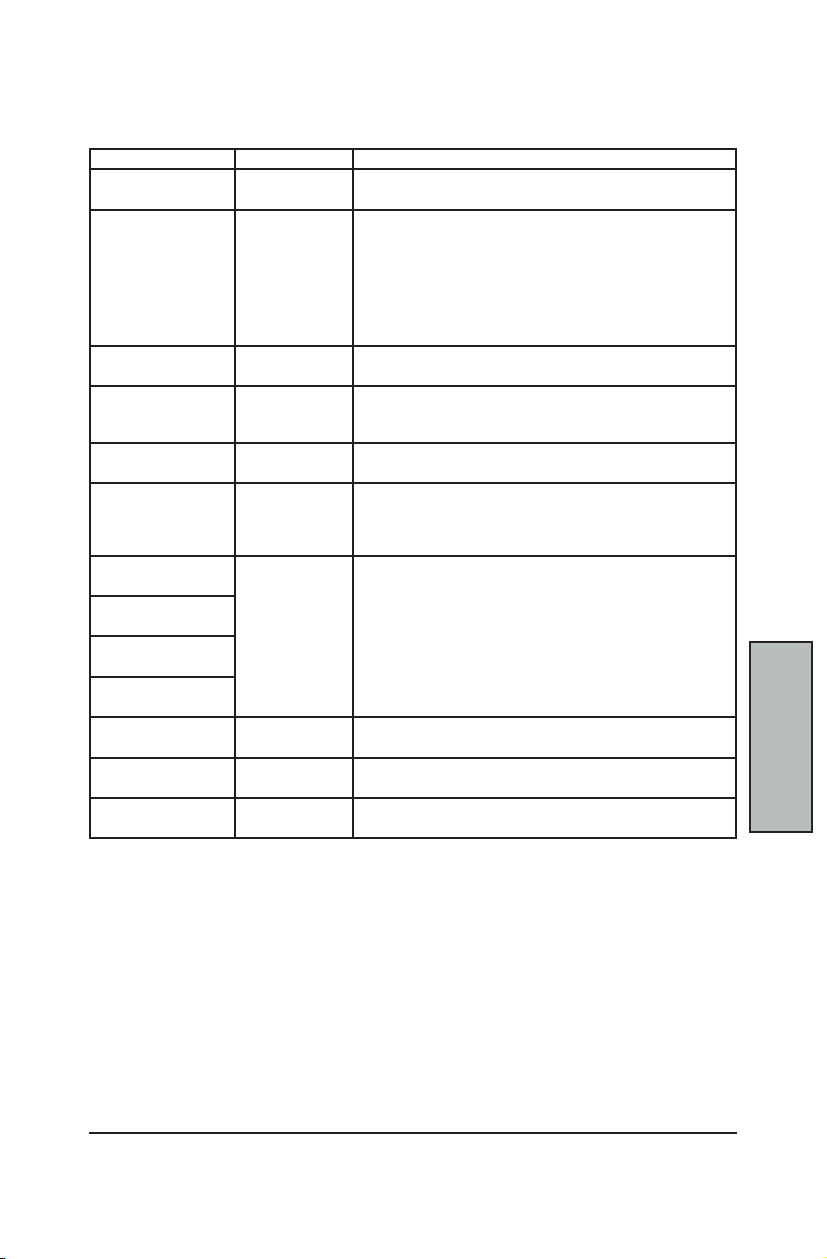
8X AGP CONTROL OPTIONS SUBMENU
This screen is displayed when you select the "8x AGP Control Options" SubMenu from the
Advanced Menu.
Advanced
AGP Operations: [Enabled]
Graphics Aperture: [64 MB]
AGP 8x Mode: [Enabled]
Fast Writes: [Disabled]
Side Band Signals: [Disabled]
Calibration Cycle Time: [64 Milliseconds]
AGP Comp Data Neg Edge Mode: [CALCOMP]
AGP Comp Data Pos Edge Mode: [CALCOMP]
AGP Comp Strobe Neg Edge Mode: [CALCOMP]
AGP Comp Strobe Pos Edge Mode: [CALCOMP]
AGP Comp Data Skew Value: [0]
AGP Comp Strobe Skew Value: [0]
F1 Help ^v Select Item –/+ Change Values F9 Setup Defaults
ESC Exit <> Select Menu Enter Select » Submenu F10 Save and Exit
8x AGP Control Options Item Specic Help
PhoenixBIOS Setup Utility
Advanced Features for the
Accelerated Graphics Port
(AGP).
Page 43
C-39
BIOS Setup
BIOS
Setup
8x AGP Control Options SubMenu continued...
Use this chart to help you congure your 8x AGP Control Option SubMenu:
Feature Options Description
AGP Operations Disabled
Graphics Aperture 32 MB
AGP 8x Mode Enabled
Fast Writes Enabled
Side Band Signals Disabled
Calibration Cycle Time 4 milliseconds
AGP Comp Data Neg
Edge Mode
AGP Comp Data Pos
Edge Mode
AGP Comp Strobe Neg
Edge Mode
AGP Comp Strobe Pos
Edge Mode
DATA 0~255 Select the value to be used with the Auto-Compensation logic,
AGP Data Skew Value 0~15 Select the value to be used with the Auto-Compensation logic.
AGP Strobe Skew
Value
Enabled
64 MB
128 MB
256 MB
512 MB
1 GB
2 GB
None
Disabled
Disabled
Enabled
16 milliseconds
64 milliseconds
256 milliseconds
CALCOMP
DATA
CALCOMP + DATA
CALCOMP - DATA
0~15 Select the value to be used with the Auto-Compensation logic.
Choose to Allow / Disallow advanced AGP operations
(DevA: 0xAB bit 8)
Selects the size of the Graphics Aperture for the AGP Video
Device.
Enables special AGP 3.0 version Signaling and Data Transfers.
If your card does NOT specify 8x support, then Disable 8x mode.
Performance Option:
Some AGP cards support the faster signal timing.
If you experience problems, try Disabling the Fast Writes.
Some cards need side-band signals to increase their
performance.
Period between cycles:
000b = 4 ms, 001b = 16 ms
010b = 64 ms, 011b - 256 ms
Compensation modes for the AGP Bus. AGP Output signal edge
drive strength compensation mode.
Either apply CALCOMP directly, apply DATA directly, add DATA
to CALCOMP or subtract DATA from CALCOMP.
CALCOMP = a calculated value from the auto-compensation
circuitry
Type in value, or use the <+> and <-> keys
Type in value, or use the <+> and <-> keys
Type in value, or use the <+> and <-> keys
Page 44

MainBoard Manual
C-40
BIOS
Setup
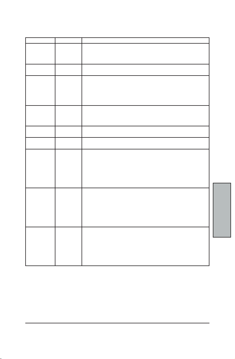
CHIPSET CONFIGURATION SUBMENU
This screen is displayed when you select the "Chip Conguration" SubMenu. In a system
with no PCI, select “Advanced Chipset Control” from the Advanced menu to display this
screen.
Advanced
Setting items on this menu to incorrect
values may cause your system to malfunction.
DRAM Bank Interleave: [Disabled]
Node Memory Interleave: [Disabled]
ECC: [Enabled]
Dram ECC: [Enabled]
ECC Scrub Redirection: [Disabled]
Chip-Kill: [Enabled]
DCACHE ECC Scrub CTL: [Disabled]
L2 ECC Scrub CTL: [Disabled]
Dram ECC Scrub CTL: [Enabled]
F1 Help ^v Select Item –/+ Change Values F9 Setup Defaults
ESC Exit <> Select Menu Enter Select » Submenu F10 Save and Exit
The chipset consists of one or more integrated circuits that act as an interface between the
CPU and much of the system’s hardware. You can use this menu to change the values in the
chipset registers and optimize your system’s performance
Chipset Conguration Item Specic Help
PhoenixBIOS Setup Utility
Setup Warning
Select Options for
Advanced Chipset
Features.
The contents of this menu depend on the chipset installed on your motherboard. Incorrect
settings can cause your system to malfunction.
NOTE
Page 45
C-41
BIOS Setup
BIOS
Setup
Chipset Conguration SubMenu continued...
Use this table in conguring the system chipset features:
Feature Options Description
Dram Bank
Interleave
Node Memory
Interleave
ECC Disabled
Dram ECC Disabled
ECC Scrub
Redirection
Chip-Kill Disabled
DCACHE ECC
Scrub CTL
L2 ECC Scrub
CTL
Dram ECC
Scrub CTL
Disabled
AUTO
Disabled
AUTO
Enabled
Enabled
Disabled
Enabled
Enabled
Disabled
40 ns
80 ns
160 ns
320 ns
640 ns
1.28 us
2.56 us
Disabled
40 ns
80 ns
160 ns
320 ns
640 ns
1.28 us
2.56 us
Disabled
1.31 ms
2.62 ms
5.24 ms
10.49 ms
20.97 ms
42.0 ms
84.0 ms
Enable this item to increase memory speed. Interleave memory blocks
across Dram chip selects.
BIOS will AUTO detect compatibility on each node.
Interleave memory blocks across Processor Nodes.
BIOS will AUTO detect compatibility of /memory System
ECC Check/Correct Mode
This is a Global enable function for all blocks within the CPU core and North
Bridge.
Note; After loading setup defaults, restart and enter setup to access Dram
ECC setup options.
If all memory in the system supports ECC (x72), enabling this will Initial
scrub Dram and enable system requests to Dram to be checked and/or
corrected.
This option only appears if the ECC option is enabled.
Enable ECC Scrubber to correect errors detected in DRAM during normal
CPU requests (Foreground Scrubbing)
Enable Chip-Kill ECC on Nodes with all x4 ECC capable DIMMs
Sets the rate of Background Scrubbing for DCACHE lines.
This option only appears if the ECC option is enabled.
Sets the rate of Background Scrubbing for CACHE lines.
This option only appears if the ECC option is enabled.
Sets the rate of BACKGROUND Scrubbing for DRAM (in addition to normal
ECC Scrubbing from system requests).
Note: BACKGROUND agent works independently of CPU requests and bus
masters, but it canNOT be enabled without rst enabling Dram ECC.
This option only appears if the ECC option is enabled.
Page 46
MainBoard Manual
C-42
BIOS
Setup
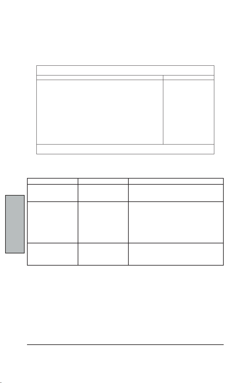
This screen is displayed when you select the "Keyboard Coniguration" SubMenu. If the
system has a PCI chipset, select “Advanced Chipset Control” from the Advanced menu to
display this screen.
This menu enables you to congure your keyboard behavior at system boot time .
use this chart to help congure your keyboard.
Keyboard auto-repeat rate 30/sec
KEYBOARD CONFIGURATION SUBMENU
Advanced
NumLock: [Auto]
Keyboard auto-repeat rate: [30/sec]
Keyboard auto-repeat delay: [1/2 second]
F1 Help ^v Select Item –/+ Change Values F9 Setup Defaults
ESC Exit <> Select Menu Enter Select » Submenu F10 Save and Exit
Feature Options Description
Numlock Auto
Keyboard auto-repeat
delay
Keyboard Conguration Item Specic Help
PhoenixBIOS Setup Utility
On
Off
26.7/sec
21.8/sec
18.5/sec
13.3/sec
10/sec
6/sec
2/sec
sec
sec
sec
1 sec
On or Off sets the keyboard NumLock status (either
ON or OFF) on boot up. "Auto" sets the NumLock
ON if it nds a numeric key pad.
Sets the number of times a second to repeat a
keystroke when the key is held down.
Selects Key Repeat Rate.
Sets the delay time after the key is held down before
it begins to repeat the keystroke.
Selects Delay before the Key Repeats
Keyboard Feature
Conguration Menu
Page 47

C-43
BIOS Setup
BIOS
Setup
I/O DEVICE CONFIGURATION SUBMENU
The CPU communicates with external devices such as printers through devices called
Input/Output (I/O) ports such as serial and parallel ports. These I/O devices require the use
of system resources such as I/O addresses and interrupt lines. If these devices are Plug
and Play, either the BIOS can allocate the devices during POST, or the operating system
can do it. If the I/O devices are not Plug and Play, they may require manually setting them
in Setup.
On some systems, the chipset manages the communication devices. Other systems have,
instead, a separate I/O chip on the motherboard for conguring and managing these
devices.
This submenu allows you to control the conguration settings for the I/O ports. Select “I/O
Device Conguration” on the Advanced Menu to display this menu and specify how you
want to congure these I/O Devices:
Advanced
Serial Port A: [Enabled]
Base I/O address: [3F8]
Parallel Port: [Enable]
Mode: [ECP]
Base I/O address: [378]
Interrupt: [IRQ5]
DMA channel: [DMA 1]
Floppy disk controller: [Enabled]
Base I/O address: [Primary]
PS/2 Mouse: [Enabled]
F1 Help ^v Select Item –/+ Change Values F9 Setup Defaults
ESC Exit <> Select Menu Enter Select » Submenu F10 Save and Exit
I/O Device Conguration Item Specic Help
PhoenixBIOS Setup Utility
Congure Seial Port A
using Options:
Disabled = No
conguration
Enabled = User
Conguration
AUTO = BIOS or OS
chooses conguration
OS Controlled =
Displayed when
controlled by OS
Page 48
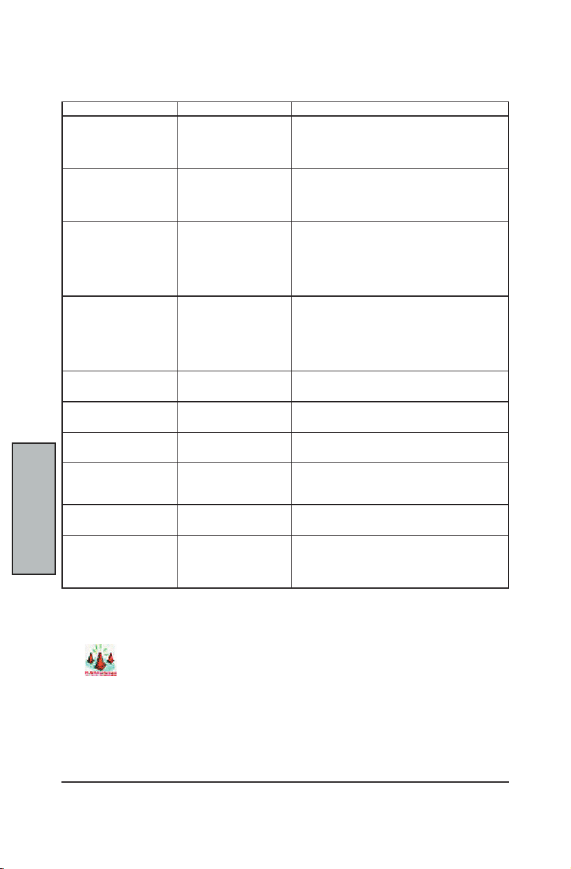
MainBoard Manual
C-44
BIOS
Setup
Use the following chart to congure the Input/Output settings:
I/O Device Conguration SubMenu continued...
Feature Options Description
Serial port A: Disabled
Enabled
Auto
Base I/O Address 3FB
2FB
3EB
2EB
Parallel Port Disabled
Enabled
Auto
Mode Output Only
Bi-Directional
EPP
ECP
Base I/O Address 378
328
Interrupt IRQ 5
IRQ 7
DMA Channel DMA 1
DMA 3
Floppy Disk Controller Disabled
Enabled
AUTO
Base I/O Address Primary
Secondary
PS/2 Mouse Disabled
Enabled
Congure Serial Ports using Options:
Disabled = No conguration
Enabled = User conguration
AUTO = BIOS or OS chooses conguration
Select the Base I/O address for the Serial Ports.
Congure the Parallel Port using Options:
Disabled turns off the port.
Enabled requires you to enter the base Input/Output
address and the Interrupt number on the next line.
Auto makes the BIOS congure the port
automatically during POST.
Set the mode for the Parallel Port using options:
Output Only = standard one-way protocol for a
parallel device (SPP)
Bi-directional = two-way protocol
EPP = Extended Parallel Port
ECP = Extended Capabilities Port
Set the Base I/O address for the Parallel Port.
Set the Interrupt for the Parallel Port.
Select which DMA (Direct Memory Access) channel
to be used by the parallel port. if using in ECP mode.
Enables the on-board legacy diskette controller.
Disabled turns off all legacy diskette drives.
Auto = BIOS or OS chooses the conguration.
Set the Base I/O address for the Floppy Disk
Controller.
Disabled = prevents any installed PS/2 mouse from
functioning, but frees up IRQ 12.
Enabled = forces PS/2 mouse port to be enabled
regardless if a mouse is present.
WARNING
If you choose the same I/O address or Interrupt for more than one port, the menu displays a
yellow asterisk (*) at the conicting settings.
Page 49
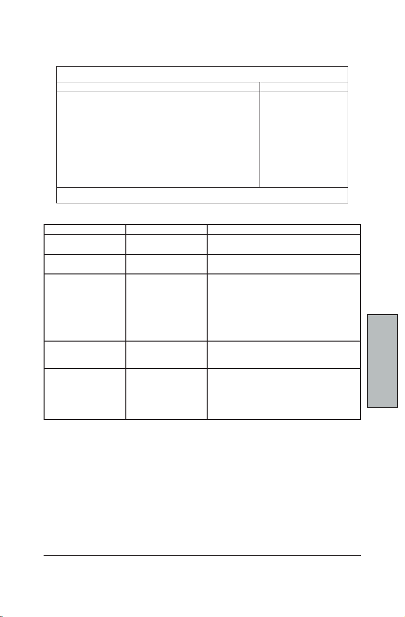
C-45
BIOS Setup
BIOS
Setup
CONSOLE REDIRECTION SUBMENU
This submenu controls the conguration to remotely control the system.
Advanced
Console Redirection Item Specic Help
PhoenixBIOS Setup Utility
COM Port Address: [Disabled]
Console Connection: [Direct]
Baud Rate: [19.2K]
Flow Control : [CTS/RTS]
Console Type: [ANSI]
F1 Help ^v Select Item –/+ Change Values F9 Setup Defaults
ESC Exit <> Select Menu Enter Select » Submenu F10 Save and Exit
Use the following chart in conguring the Console Redirection submenu:
Feature Options Description
COM Port Address Disabled
On-board COM A
Console Connection Direct
Via modem
Baud Rate 300
1200
2400
9600
19.2K
38.4K
57.6K
115.2K
Flow Control None
XON/XOF
CTS/RTS
Console Type vt100
vt100 8bit
ANSI 7bit
ANSI
vt100 plus
UTF8
If Enabled, it will use a port on the MainBoard.
Indicate whether the console is connected directly to
the system or a modem is used to connect.
Enables the specied baud rate.
Enables Flow Control.
XON/XOF is software ow control
CTR/RTS is hardware ow control
Enables the specied console type.
Additional Setup
menus to congure
the console.
If enabled, it
will use a port
on the motherboard
Page 50

MainBoard Manual
C-46
BIOS
Setup
PCI DEVICES SUBMENU
If the system has a PCI bus, selecting “PCI Devices” from the Advanced menu displays the
following submenu:
PCI Devices are devices equipped for operation with a PCI (Peripheral Component
Interconnect) bus, a standardized Plug-and-Play hardware communication system that
connects the CPU with other devices.
Advanced Exit
»
Onboard Device Control
»
PCI/PNP IRQ Exclusion
»
PCI/PNP UMB Exclusion
F1 Help ^v Select Item –/+ Change Values F9 Setup Defaults
ESC Exit <> Select Menu Enter Select » Submenu F10 Save and Exit
PhoenixBIOS Setup Utility
PCI Conguration Item Specic Help
Additional Setup
Menus to congure
PCI devices
Page 51
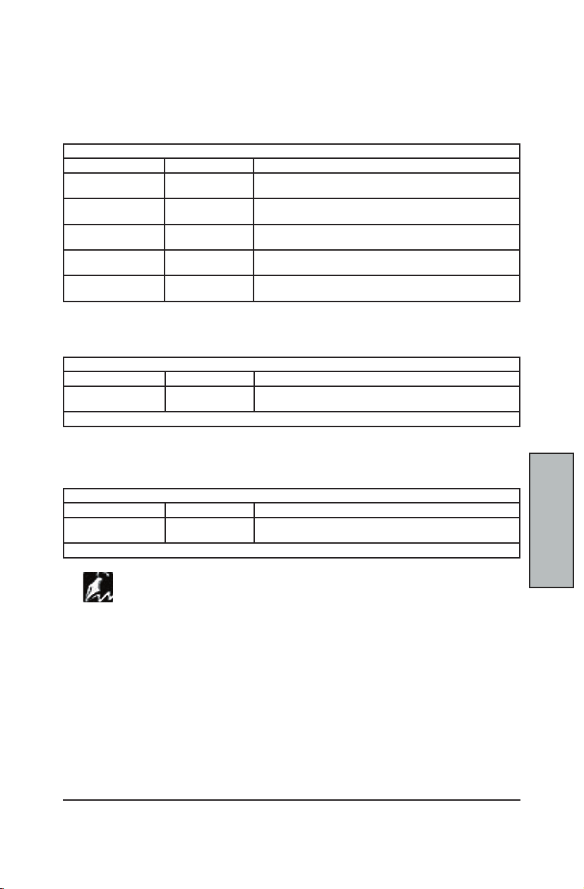
C-47
BIOS Setup
BIOS
Setup
PCI Devices SubMenu continued...
Use this submenu to congure the PCI devices installed on your system by selecting each
individual submenu. Use the following chart in conguring the PCI devices submenus:
OnBoard Device Control SubMenu
The Onboard Device Control SubMenu is for conguring specic PCI devices.
Onboard Device Control
Feature Options Description
Onboard LAN1/2 Enabled
Disabled
Option ROM Scan Enabled
Disabled
Onboard SATA Enabled
Disabled
Onboard 1394 Enabled
Disabled
Onboard AC97 Enabled
Disabled
Enable / Disable the onboard LAN function and LAN port.
Initialize device expansion ROM.
Enables the onboard Serial ATA RAID function.
Enable / Disable onboard IEEE 1394 Controller
Enable / Disable onboard AC97 Audio Controller
PCI/PNP IRQ Exclusion SubMenu
The PCI/PNP IRQ Exclusion SubMenu is for reserving specic IRQs for use by legacy ISA
devices.
PCI/PNP IRQ Exclusion
Feature Options Description
IRQ 3/4/5/7/10/11 Available
Reserved
Items marked with an asterisk (*) indicate a DMA, IRQ, I/O, or memory resource conict with another device.
Reserves the specied IRQ for use by Legacy ISA Devices.
PCI/PNP UMB Exclusion SubMenu
The PCI/PNP UMB Exclusion SubMenu is for reserving specic upper memory blocks for
use by legacy ISA devices.
PCI/PNP UMB Exclusion
Feature Options Description
C800 – CBFF ~
DC00 - DFFF
*Items marked with an asterisk indicate a DMA, IRQ, I/O, or memory resource conict with another device.
Available
Reserved
Reserves the specied block of upper memory for use by
Legacy ISA Devices.
The contents of this menu depend on the devices installed on your system. Incorrect settings
NOTE
can cause your system to malfunction. To correct mistakes, return to Setup and restore the
System Defaults (F9).
Page 52
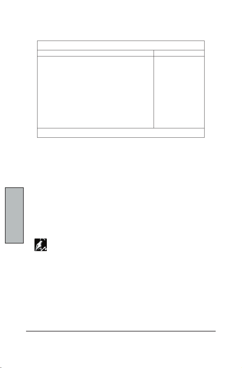
MainBoard Manual
C-48
BIOS
Setup
SECURITY MENU
The Security menu selection in the menu bar on top of the screen displays the following:
Main Advanced Security Power Boot Server Exit
PhoenixBIOS Setup Utility
Item Specic Help
Use this menu to specify your security settings. The settings here determine who has
access to the BIOS setup utility program and to the system.
The Setup Utility allows you to specify passwords in the Security menu. The passwords
control access to the BIOS and certain Security menu options during system startup.
The passwords are NOT case sensitive. In other words, a password can be entered using
either upper or lower case letters.
The "Supervisor Password" controls access to the BIOS Setup Utility screen and can be
used to access the system during boot up. The "User Password" controls the usage of the
system. If so enabled, the end-user could be required to enter a password to be able to
boot up the system.
Supervisor Password is: Clear
User Password is: Clear
Set Supervisor Password:[Enter]
Set User Password: [Enter]
Password on boot: [Disabled]
Fixed disk boot sector: [Normal]
Diskette access: [Supervisor]
F1 Help ^v Select Item –/+ Change Values F9 Setup Defaults
ESC Exit <> Select Menu Enter Select » Submenu F10 Save and Exit
Supervisor
Password controls
access to the
setup utility.
PASSWORDS
When Passwords are set and Enabled in the BIOS, the system will prompt for passwords in
NOTE
the appropriate situations.
* During System Boot and BIOS entry, if three (3) WRONG passwords are entered,
the system will be disabled and will require the user to reset the system.
Page 53
C-49
BIOS Setup
BIOS
Setup
SETTING AND USING PASSWORDS
The Security Menu allows you to set the Supervisor and User passwords for the system.
Select the appropriate options and press <Enter> to start the process.
Set Supervisor Password
This eld allows you to set the Supervisor password. To set the Supervisor password,
highlight this eld and press the [Enter] key. The following dialog box appears:
Set Supervisor Password
Enter New Password [ ]
Conrm New Password [ ]
Type the password and press the [Enter] key. You can type up to eight alphanumeric
characters. Symbols and other keys can NOT be used in the password. To conrm the
password, type the password again and press the [Enter] key. The Supervisor password is
now set. This password allows full access to the BIOS Setup menus.
To Clear the Supervisor Password
To clear the Supervisor Password, highlight the "Set Supervisor Password" eld and press
the [Enter] key. The following dialog box appears:
Set Supervisor Password
Enter Current Password [ ]
Enter New Password [ ]
Conrm New Password [ ]
* Enter the current password.
* Leave the Enter New Password eld blank and press [Enter] twice. The
Password is now cleared
Set User Password
This eld allows you to set the User password. (The Supervisor password must be set
before the User password.) To set the User password, follow the instructions for setting the
Supervisor password. The User password allows restricted access to the Setup menus.
Feature Options Description
Password on boot Disabled
Enabled
Fixed Disk Boot Sector Normal
Write Protect
Diskette Access User
Supervisor
This option requires the Supervisor password to be set to function.
When enabled, the system will require either the Supervisor or
User password before the system will bootup.
This option requires the Supervisor password to be set to function.
When set to Normal, the system will allow normal access to the
HDD boot sector. When set to Write Protect, the BIOS blocks all
access to the boot sector.
This option requires the Supervisor or User password be set to
function. When set to Supervisor or User, the system will prompt
the user for the supervisor or user password before allowing
access to the oppy diskette drive.
Write protecting the HDD boot sector will protect the HDD against boot sector viruses
NOTE
However, this option may interfere with the normal operation of certain operating systems or
anti-virus programs which normally need access to the boot sector area.
Page 54
MainBoard Manual
C-50
BIOS
Setup
POWER MENU
Use this menu to specify your settings for Power Management. Remember that the options
available depend upon the hardware installed in your system. Those shown here are from
a typical system.
The Power menu selection in the menu bar on top of the screen displays the following:
A power-management system reduces the amount of energy used after specied periods
of inactivity. The Setup menu pictured here supports a Full On state, a Standby state with
partial power reduction, and a Suspend state with full power reduction.
Main Advanced Security Power Boot Server Exit
ACPI Enabled: [Yes]
ACPI SRAT Table: [Disabled]
Spread spectrum modulation [No]
Suppress Unused PCI Slot Clocks [Yes]
WakeUp On LAN/PME: [Enabled]
Power Savings: [Customize]
Standby Timeout: [15 sec]
Auto Suspend Timeout: [15 sec]
Resume On Time: [Off]
Resume Time: [00:00:00]
Resume Date: [00/00/0000]
After Power Failure: [Last State]
F1 Help ^v Select Item –/+ Change Values F9 Setup Defaults
ESC Exit <> Select Menu Enter Select » Submenu F10 Save and Exit
PhoenixBIOS Setup Utility
Item Specic Help
Select Power
Management Mode.
Choosing modes
changes system
power management
settings. Maximum
Power Savings
conserves the
greatest amount of
system power while
Maximum Performance
conserves power
but allows greatest
system performance.
To alter these
settings, choose
Customize. To
turn off power
management, choose
Disable.
Use the Advanced Options on this menu to specify whether or not the activity of interrupts
can terminate a Standby or Suspend state and restore Full On. Do NOT change these
settings if you do not know which devices use the interrupts.
Page 55

C-51
BIOS Setup
BIOS
Setup
Power Menu continued...
Use this chart to help congure the system's power settings:
Feature Options Description
ACPI Enabled No
ACPI SRAT Table Disabled
Spread Spectrum
Modulation
Suppress Unused
PCI Slot Clocks
WakeUp On
LAN/PME
Power Savings Disabled
Maximum Power-Savings
Standby Timeout Off
Auto Suspend
Timeout
Resume On Time Off
Resume Time HH/MM/SS Specify the time when the system is to wake up.
Resume Date MM/DD/YYYY Specify the date when the system is to wake up.
After Power
Failure
Yes
Enabled
No
0.10%
0.40%
0.70%
1.00%
1.30%
1.60%
2.00%
Yes
No
Disabled
Enabled
Customize
Maximum Performance
1 min
2 min
4 min
6 min
8 min
12 min
16 min
Disabled
5 min
10 min
15 min
20 min
30 min
40 min
60 min
On
Stay Off
Last State
Power On
This mainboard supports ACPI (Advanced Conguration
and Power management Interface). Use this item to enable
or disable the ACPI feature. ACPI is a power management
specication that makes hardware status information
available to the operating system. ACPI enables a PC to turn
its peripherals on and off for improved power management
especially in portables. It also allows the PC to be turned on
and off by external devices, so that the touch of a mouse or the
press of a key will “wake up” the machine.
Enables and disables the ACPI 2.0 SRAT (Static Resource
Afnity Table) for ccNUMA systems
If you enable spread spectrum, it can signicantly reduce the
EMI (Electro-Magnetic Interference) generated by the system.
Enables frequency spreading on clock generators to reduce
EMI emissions.
When enabled, the BIOS will disable the unused clock signals
of free PCI slots to reduce EMI and power consumption.
Enables WakeUp on LAN/PME support.
Maximum Power-Savings = conserves the greatest amount of
system power.
Maximum Performance = conserves power but allows greatest
system performance.
To alter these settings, choose Customize.
To turn off power management, choose Disabled.
Amount of time the system needs to be in Idle mode before
entering Standby mode.
Standby mode turns off various devices in the system,
including the screen, until you start using the computer again.
Amount of time the system needs to be in Standby mode
before entering the Suspend mode.
Enabled, it wakes the system up at a specic time.
Sets the mode of operation if an AC Power Loss occurs.
Stay Off = returns the system to an OFF state.
Power On = returns the system to a Full ON state.
Last State = returns the system to the state when the AC
Power Loss occured.
Page 56
MainBoard Manual
C-52
BIOS
Setup
BOOT MENU
After you turn on your computer, it will attempt to load an operating system (such as Windows
98) from the rst device set in the Boot Menu. If it cannot nd an operating system on that
device, it will attempt to load it from one or more other devices in the order specied in the
Boot Menu. Boot devices can include: hard drives, oppy drives, CD-ROMs, removable
devices (e.g., Iomega Zip drives), and network cards.
Specifying any device as a boot device on the Boot Menu requires the availability of an
operating system on that device. Most systems come with an operating system already
installed on hard-drive C:\.
The Boot menu selection in the menu bar on top of the screen displays the following:
NOTE
Main Advanced Security Power Boot Server Exit
CD-ROM Drive
–Hard Drive
Primary Master
Bootable Add-in Cards
–Removable Devices
Legacy Floppy Drives
Network Boot
MBA v6.20.0 Slot 0230
F1 Help ^v Select Item –/+ Change Values F9 Setup Defaults
ESC Exit <> Select Menu Enter Select » Submenu F10 Save and Exit
PhoenixBIOS Setup Utility
Item Specic Help
Keys used to view or
congure devices:
<Enter> expands or
collapses devices with
a + or <Ctrl+Enter> expands all
<Shift+1> enables or
disables a device
<+> and <-> moves the
device up or down
<n> may move removable
devices between Hard
Disk and Removable
Devices
<d> removes a device
that is not installed
Use this menu to arrange to specify the priority of the devices from which the BIOS will
attempt to boot the Operating System.
In the example above, the BIOS will rst attempt to boot from the CD-ROM Drive. Failing
that, it will then attempt to boot from the Primary Master Hard Disk, and so on down the list.
Removable Devices, Hard Drive, and Network Boot are the generic types of devices on
your system from which you can boot an operating system. You may have more than one
device of each type. If so, the generic type is marked with a plus sign. Use the <Enter> key
to expand or collapse the devices marked with a <+> or <->. Press <Ctrl+Enter> to expand
all such devices
Page 57

C-53
BIOS Setup
BIOS
Setup
Boot Menu continued...
To change a device’s priority on the list, rst select it with the up-or-down arrows, and move
it up or down using the <+> and <-> keys. Pressing <n> moves a device between the
Removable Devices and Hard Drive. Pressing <Shift+1> enables or disables a device.
Pressing <d> removes a device that is not installed.
Feature Options Description
Hard Drive Primary Master To attempt to boot the primary master IDE Device
Bootable Add-in Cards To attempt to boot from Bootable cards (such as LAN or
Removable Devices Legacy Floppy Drive The computer attempts to boot from the oppy disk drive.
CD-ROM Drive The computer attempts to boot from the CD-ROM drive.
Network Boot The computer attempts to boot from the network through
MBA v. 6.20.0
Slot 0230
SCSI cards)
the additional LAN card (if installed)
The computer attempts to boot from the network through
the On-Board LAN connection.
SERVER MENU
The Server menu selection in the menu bar on top of the screen displays the following:
Main Advanced Security Power Boot Server Exit
Display without KB ERR MSG: [No]
»
Hardware Monitor
PhoenixBIOS Setup Utility
Item Specic Help
Control the POST
Error Message
Display or not when
without KB
F1 Help ^v Select Item –/+ Change Values F9 Setup Defaults
ESC Exit <> Select Menu Enter Select » Submenu F10 Save and Exit
Many servers are run as "Headless" appliances (no KB, mouse, or monitor connected).
Under normal settings, if no keyboard is detected, the POST will display an error message
and pause the system boot, as it is a requirement for system boot up. This screen allows
the end-user to NOT have that error message displayed, and allows the system to boot up
normally even when a keyboard is not detected.
Here are the options for the Server Menu:
Feature Options Description
Display without KB ERR
MSG
Yes
No
Controls the POST Error Message Display.
Use the "Yes" option to suppress the POST KB error message
and allow the system to boot even if no KB is detected
The "No" option will continue to display the error message and
pause the system boot up if no KB is detected.
Page 58
MainBoard Manual
C-54
BIOS
Setup
HARDWARE MONITOR SUBMENU
Selecting “Hardware Monitor” from the Server menu displays the following submenu:
Server
CPU 0 Vcore = 1.59 V
CPU 1 Vcore = 1.104 V
V (bat) = No Function
V (Vdd) = 5.10 V
V (Vcc3) = 3.30 V
CPU 0 Temperature = 56 ºC
CPU 1 Temperature = 58 ºC
VH = 1.2725 V
VCC25 = 2.5067 V
CPU Fan 0 Speed = No Function
CPU Fan 1 Speed = No Function
System Fan Speed = 3037 RPM
F1 Help ^v Select Item –/+ Change Values F9 Setup Defaults
ESC Exit <> Select Menu Enter Select » Submenu F10 Save and Exit
PhoenixBIOS Setup Utility
Hardware Monitor Item Specic Help
All items on this
menu can NOT be
modied in User
mode. If any items
require changes,
please consult your
System Supervisor.
Page 59

C-55
BIOS Setup
BIOS
Setup
EXIT MENU
The Exit menu selection in the menu bar on top of the screen displays the following:
Main Advanced Security Power Boot Server Exit
PhoenixBIOS Setup Utility
Item Specic Help
Exit Saving Changes
Exit Discarding Changes
Load Setup Defaults
Discard Changes
Save Changes
F1 Help ^v Select Item –/+ Change Values F9 Setup Defaults
ESC Exit <> Select Menu Enter Select » Submenu F10 Save and Exit
The following sections describe each of the options on this menu. Note that <Esc> does not
exit this menu. You must select one of the items from the menu or menu bar to exit.
Exit System Setup
and save your
changes to CMOS.
Exit Saving Changes
After making your selections on the Setup menus, select “Exit Saving Changes” or “Save
Changes” to see a screen similar to the following:
Setup Conrmation
Save conguration changes and exit now?
[Yes] [No]
* Select Yes and press <Enter> to save the changes.
Both procedures will store the selections displayed in the menus into the CMOS (short for
“battery-backed CMOS RAM”) a special section of memory that stays on after you turn
your system off. The next time you boot your computer, the BIOS congures your system
according to the Setup selections stored in the CMOS.
During boot up, PhoenixBIOS attempts to load the values saved in CMOS. If those values
cause the system boot to fail, reboot and press <F2> to enter Setup. In Setup, you can
restore the Default Values <F9> or try to change the selections that caused the boot to fail.
Exit Discarding Changes
Use this option to exit Setup without saving in the CMOS any new selections or changes you
may have made. The selections previously in effect remain in effect.
Page 60
MainBoard Manual
C-56
BIOS
Setup
To load the default values for all the Setup menus, select “Load Setup Defaults” from the
Main Menu. The program displays this message:
If, during boot up, the BIOS program detects a problem in the integrity of values stored in
CMOS, it displays these messages:
The CMOS values have been corrupted or modied incorrectly (perhaps by an application
program that modies stored CMOS data.)
Press <F1> to resume the boot or <F2> to run Setup with the ROM default values already
loaded into the menus. You can make other changes before saving the values to CMOS.
If, during a Setup Session, you change your mind about changes you have made and
have not yet saved the values to CMOS, you can restore the values you previously saved
to CMOS.
Selecting “Discard Changes” on the Exit menu will update all the selections with the
previous values stored in the CMOS and displays this message:
Exit Menu continued...
Load Setup Defaults
Setup Conrmation
Load default conguration now?
[Yes] [No]
* Select Yes and press <Enter> to load the default conguration.
System CMOS checksum bad - run SETUP
Press <F1> to resume, <F2> to Setup
Discard Changes
Setup Conrmation
Load previous conguration now?
[Yes] [No]
* Select Yes and press <Enter> to load the previous conguration.
Save Changes
Selecting “Save Changes” saves all the selections without exiting Setup. Selecting this
option will display this message:
Setup Conrmation
Save conguration changes now?
[Yes] [No]
* Select Yes and press <Enter> to save conguration changes and continue
working in BIOS Setup.
You can return to the other menus if you want to review and change your selections.
Page 61
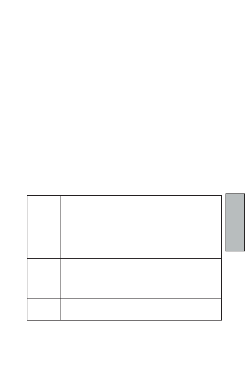
C-57
BIOS Setup
BIOS
Setup
PHOENIX BOOT UTILITIES
This MainBoard comes with the following boot utilities:
* Phoenix QuietBoot™: Phoenix QuietBoot displays a graphic illustration rather
than the traditional POST messages while keeping you informed of diagnostic
problems.
* Phoenix MultiBoot™: Phoenix MultiBoot is a boot screen that displays a selection
of boot devices from which you can boot your operating system.
USING PHOENIX QUIETBOOT
Right after you turn on or reset the computer, Phoenix QuietBoot displays the QuietBoot
Screen, a graphic illustration created by the computer manufacturer instead of the textbased POST screen, which displays a series of PC diagnostic messages.
To exit the QuietBoot screen and run Setup, display the MultiBoot menu, or simply display
the PC diagnostic messages, you can simply press one of the hot keys described below.
The QuietBoot Screen stays up until just before the operating system loads unless one of
the following actions occurs:
* Press <Esc> to display the diagnostic/POST screen
* Press <F2> to enter Setup
* POST issues an error message
* The BIOS or an option ROM requests keyboard input
Here are the possible QuietBoot scenarios in greater detail:
When Escape is
pressed
Press <F2> to
enter Setup
POST issues an
error message
The BIOS
or an option
ROM requests
keyboard input
Pressing <Esc> switches to the POST screen and takes one of two actions:
1. If MultiBoot is installed, the boot process continues with the POST screen
until the end of POST, and then displays the Boot First Menu, text-based with
these options:
* Load the operating system from the boot device of your choice.
* Enter the BIOS Setup Utility.
* Exit the Boot First Menu (with <Esc>) and load the operating system from
the boot devices specied in the BIOS Setup.
OR
2. If MultiBoot is not installed, the boot process continues as usual.
Pressing <F2> at any time during POST switches to the POST screen (if not already
displayed) and enters Setup.
Whenever POST detects a non-fatal error, QuietBoot switches to the POST screen and
displays the errors. It then displays this message:
Press <F1> to resume, <F2> to Setup
Press <F1> to continue with the boot. Press <F2> if you want
to correct the error in Setup.
If the BIOS or an Option ROM (add-on card) requests keyboard input, QuietBoot switches
over to the POST screen and the Option ROM display prompts the user to enter the
information. POST then continues from there with the regular POST screen.
Page 62
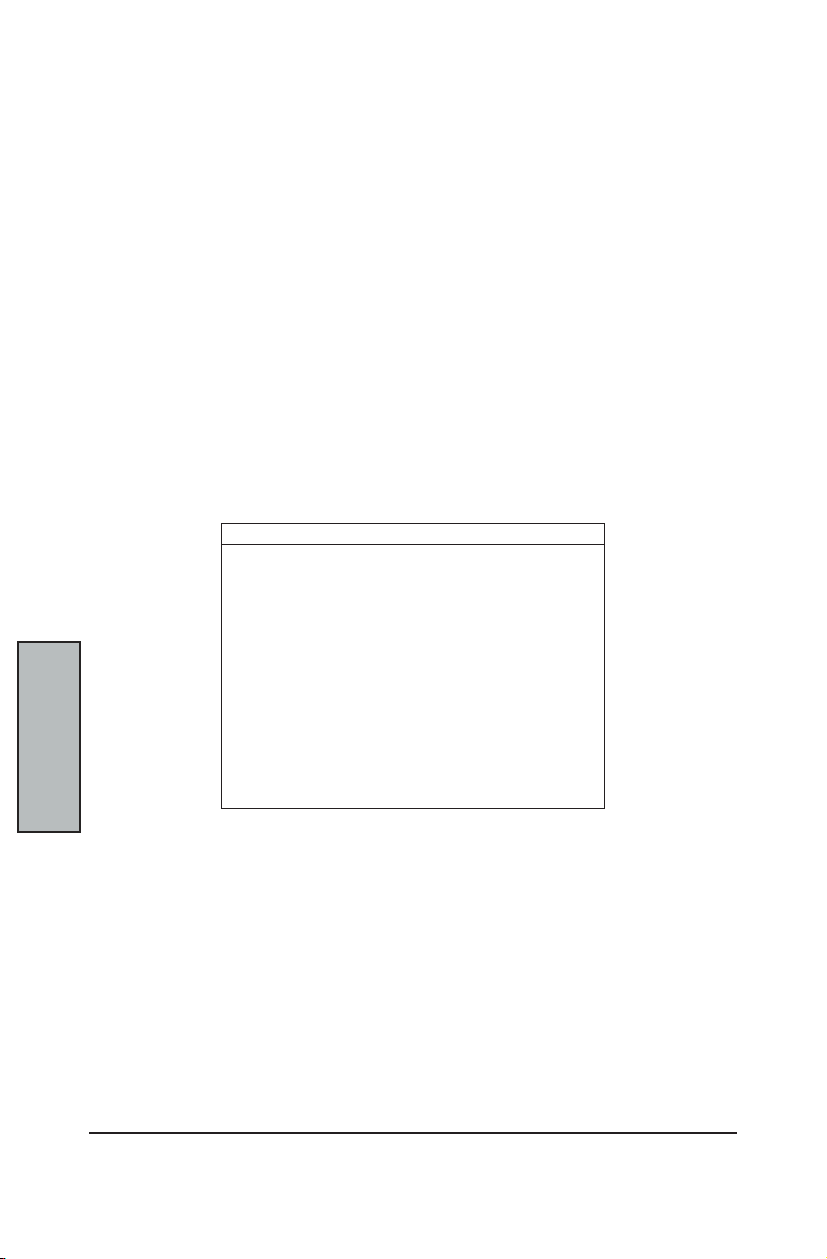
MainBoard Manual
C-58
BIOS
Setup
Phoenix MultiBoot expands your boot options by letting you choose your boot device on
startup, which could be a hard disk, oppy disk, or a CD-ROM. You can congure your boot
device in Setup, or you can choose a different device each time you boot during POST by
selecting your boot device in The Boot First Menu.
MultiBoot consists of:
Refer to the Boot Menu in BIOS Setup for more information on the Setup Boot Menu. The
following describes the Boot First Menu.
Display the Boot First Menu by pressing <Esc> during the POST. In response, the BIOS rst
displays the message, “Entering Boot Menu ...” and then displays the Boot Menu at the end
of POST. Use the menu to select any of these options:
PHOENIX MULTIBOOT
* The Setup Boot Menu
* The Boot First Menu
The Boot First Menu
* Override the existing boot sequence (for this boot only) by selecting another
boot device. If the specied device does not load the operating system, the
BIOS reverts to the boot sequence stored in Setup.
* Enter Setup.
* Press <Esc> to continue with the existing boot sequence
Boot Menu
Select boot device or Setup.
Use the Up and Down arrows to select the Boot
First device, then press <Enter> or <Esc> to exit.
1. Hard Drive
2. ATAPI CD-ROM
3. Diskette Drive
4. Removable Devices
5. MBA v6.20.0 Slot 0230
<Setup>
If there is more than one bootable hard drive, then the rst one in the Setup Boot menu is
the one represented here.
Page 63

C-59
BIOS Setup
BIOS
Setup
BIOS FLASH UPGRADE UTILITY
Phoenix Phlash gives you the ability to update your BIOS from a oppy disk without having
to install a new ROM BIOS chip.
Phoenix Phlash is a utility for “ashing” (copying) a BIOS to the Flash ROM installed on your
computer from a oppy disk. A Flash ROM is a Read-Only Memory chip that you can write to
using a special method called “ashing.” Use Phoenix Phlash for the following tasks:
* Update the current BIOS with a new version.
* Restore a BIOS when it has become corrupted.
* Installation
Phoenix Phlash is shipped on a oppy disk with your computer as a compressed le called
CRISDISK.ZIP that contains the following les:
CRISDISK.BAT Executable le for creating the Crisis Recovery Diskette.
PHLASH.EXE Programs the ash ROM.
PHLASH16.EXE Performs platform-dependent functions.
BIOS.ROM Actual BIOS image to be programmed into ash ROM.
MINIDOS.SYS Allows the system to boot in Crisis Recovery Mode.
MAKEBOOT.EXE Creates the custom boot sector on the Crisis Recovery Diskette.
Installing Phoenix Phlash
To install Phoenix Phlash on your hard disk, follow this simple procedure:
1. Insert the distribution diskette into drive A:
2. Unzip the contents of CRISDISK.ZIP into a local directory, presumably
C:\PHLASH16.
3. Store the distribution diskette in a safe place.
CREATE A CRISIS RECOVERY DISKETTE
If the OEM or dealer from whom you purchased your system has not provided you with one,
then you should create a Crisis Recovery Diskette before you use the Phlash utility.
If you are unable to boot your system or successfully load the Operating System, the BIOS
may have been corrupted, in which case you will have to use the Crisis Recovery Diskette
to reboot your system.
There are several methods that you can use to create the Crisis Recovery Diskette. Below
is one recommended procedure.
1. Be sure you have successfully installed the Phlash Utility onto your hard disk.
2. Insert a clean diskette into drive A: or B:
3. From the local directory, enter the following: CRISDISK [drive]: where [drive]
is the letter of the drive into which you inserted the diskette. For help, type
CRISDISK /? or CRISDISK /h.
CRISDISK.BAT formats the diskette, then copies MINIDOS.SYS, VGABIOS.EXE
(if available), PHLASH.EXE, PLATFORM.BIN and BIOS.ROM to the diskette, and
creates a custom boot sector.
4. Write protect and label the Crisis Recovery Diskette
NOTE
You can only supply a volume label after the Crisis Recovery Diskette has been formatted
and the necessary les copied because MINIDOS.SYS must occupy the rst directory entry
for the diskette to boot properly.
Page 64

MainBoard Manual
C-60
BIOS
Setup
If the BIOS image (BIOS.ROM) changes due to an update or bug x, you can easily update
the Crisis Recovery Diskette.
You can run Phoenix Phlash in one of two modes:
For your own protection, be sure your have a Crisis Recovery Diskette ready to use before
executing Phlash.
Use this mode to update or replace your current BIOS. To execute Phlash in this mode,
move to the directory into which you have installed Phoenix Phlash and type “Phlash” at
the prompt:
Phoenix Phlash automatically updates or replaces the current BIOS with the one which your
OEM or dealer supplies you (it's a .ROM le).
Command Example:
Syntax:
UPDATING THE CRISIS RECOVERY DISKETTE
* Simply copy the new BIOS.ROM image onto the Crisis Recovery Diskette. No
further action is necessary.
EXECUTING PHOENIX PHLASH
* Command Line Mode
* Crisis Recovery Mode
WARNING
Command Line Mode
C:\Phlash> phlash16 [lename] /BBL /C
C:\Phlash> phlash16 HDAMB_120.ROM /BBL /C
phlash16 Phlash command name
HDAMB_120.ROM Filename of new BIOS ROM supplied by dealer
/BBL Flash the Boot Block
/C Clean CMOS
Phlash may fail if your system is using memory managers, in which case the utility displays
the following message:
Cannot ash when memory managers are present.
If you see this message after you execute Phlash, you must disable the memory manager on
your system. To do so, follow the instructions in the following sections.
Page 65
C-61
BIOS Setup
BIOS
Setup
DISABLING MEMORY MANAGERS
To avoid failure when ashing, you must disable the memory managers that load from
CONFIG.SYS and AUTOEXEC.BAT. There are two recommended procedures for disabling
the memory managers. One consists of pressing the <F5> key (if you are using DOS 5.0 or
above), and the other requires the creation of a boot diskette.
Diabling with DOS 5.0 (or later version)
For DOS 5.0 and later, follow the two steps below to disable any memory managers on your
system. If you are not using at least DOS 5.0, then you must create a boot diskette to bypass
any memory managers (See Create a Boot Diskette, below).
1. Boot DOS 5.0 or later version. (In Windows 95, at the boot option screen, choose
Option 8, “Boot to a previous version of DOS.”)
2. When DOS displays the “Starting MS-DOS” message, press <F5>.
After you press <F5>, DOS bypasses the CONFIG.SYS and AUTOEXEC.BAT
les, and therefore does not load any memory managers.
3. Go to the Phlash directory, and you can now execute Phlash.
Create a Boot Diskette
To bypass memory managers in DOS versions previous to 5.0, follow this recommended
procedure:
1. Insert a diskette into your A: drive.
2. Enter the following from the command line: Format A: /S
3. Reboot your system from the A: drive.
Your system will now boot without loading the memory managers, and you can
then execute Phlash.
4. move to the Phlash directory, and you are now free to execute Phlash.
Page 66

MainBoard Manual
C-62
Appendix
Troubleshooting
Troubleshooting Flowchart
Here are some owcharts to help you check for common problems encountered during
system assembly
Unexpected
Symptom
Turn OFF the system power and unplug the AC power cord.
Remove all add-on cards and peripherals including VGA,
Check that the CPU, memory modules, mouse, and keyboard
are properly installed on the mainboard and that the 115/230V
Floppy, IDE and ATAPI devices.
Check that all jumper settings are correct.
switch on the power is properly set.
Then, connect onboard VGA port to a monitor.
Contact your
authorized
dealer to
check your
system.
Plug the power cord into the onboard power connector(s) and
Make sure the system is still in a soft-OFF state.
Clear the CMOS using the Clear CMOS Header
NO
turn ON the power supply.
on the Mainboard
Power-On the system and check that
the power supply is working and that the
fans connected to the mainboard are ON
YES
Check to see that the
NO
VGA card or
monitor may
be defective
POST screen appears on
the monitor.
YES
Continue to
Next Page of
Flowchart
Page 67

C-63
Appendix
Appendix
Troubleshooting Flowchart continued...
Press <Ctrl>+<Alt>+<Del> key simultaneously
Check that the system can be re-booted.
YES
During system boot, press the <F2> key to enter BIOS Setup.
Select <Load Optimal Defaults> in the
Power OFF the system and re-connect the oppy and IDE
cables to the onboard FDD and IDE connectors.
Power ON the system and check to see that
YES
If the system boots up successfully, but the Operating System
still does NOT start up, then you will need to re-install the
operating system you intend to use on this system
to reboot the system
NO
<Exit> Menu of BIOS Setup
NO
the system can boot successfully.
(i.e. Win98,Win NT, Win2000, etc.)
Keyboard
may be
defective
IDE cable or
Hard Disk may
be defective
END
WARNING
Before inserting or installing any add-on cards or hardware components in the MainBoard,
always remember to FIRST disconnect the power cord.
Page 68

MainBoard Manual
C-64
Appendix
Symptom Checklist
Use this chart for more detailed information about some common problems that occur
during assembly and in the mainetnance of systems.
Symptom Check point
No Power
(FAN is not spinning)
Able to power ON
the system (FAN is
spinning), but NO
screen display.
Memory Error(s) * Check that the memory DIMM modules are inserted properly into the DIMM sockets.
* Make sure that no short circuit exists between the mainboard and chassis
* Check that all jumpers are set to their default positions.
* Check that the 115V/230V switch on the power supply is properly set.
* Check that the CPU is properly inserted in the CPU socket.
* Check that the power connector of the CPU fan is plugged in the correct position.
* Turn the power switch ON and OFF to test the system.
* Check the power of the battery on the mainboard.
(In general, the battery voltage is around 3VDC)
* Disconnect and remove all components from the mainboard except for the CPU,
memory modules, and the CPU fans.
* Check that the memory is Registered ECC DIMM. Refer to Appendix A:
Recommended Memory Modules or contact your authorized dealer for a list of
qualied memory vendors and models.
* Check that all jumpers are set to their default positions.
* Clear the CMOS through the Clear CMOS header.
* Check that the onboard VGA port and the monitor are properly connected.
* Check that you are using a 400 FSB CPU and PC2100/PC2700 (DDR266/DDR333)
Memory modules in the MainBoard. If not, change the CPU to 400 FSB or memory to
PC2100/PC2700 (DDR266/DDR333) and try to power ON the system again.
* Use the onboard speaker to aide in determining the problem.
* Check to see if different speed memory modules are mixed in and used in the
MainBoard memory banks. Verify that the BIOS setup is congured for the fastest
speed of RAM used. RioWorks recommends that you always install the same speed
DDR RAM in your system.
* Make sure all your memory modules in the MainBoard are compliant with the
PC2100/PC2700 (DDR266/DDR333) Specications and that they appear either in
Appendix A: Recommended Memory Modules or on your authorized dealer's Qualied
Vendor's List of Memory Modules.
Page 69

C-65
Appendix
Appendix
POST Errors and Beep Codes
PhoenixBIOS 4.0 Release 6.0
When you turn on or reset an IBM-compatible PC, the BIOS rst performs a number of tasks,
called the Power-On-Self-Test (POST). These tasks test and initialize the hardware and then
boot the Operating System from the hard disk.
At the beginning of each POST task, the BIOS outputs the test-point error code to I/O port
80h. Programmers and technicians use this code during troubleshooting to establish at
what point the system failed and what routine was being performed. Some motherboards
are equipped with a seven segment LED display that displays the current value of port
80h.
For production boards which do not contain the LED display, you can purchase an
installable “Port 80h” card that performs the same function. If the BIOS detects a terminal
error condition, it issues a terminal-error beep code, attempts to display the error code
on the upper left corner of the screen and on the port 80h LED display, and halts POST. It
attempts repeatedly to write the error to the screen. This attempt may “hash” some CGA
displays.
If the system hangs before the BIOS can process the error, the value displayed at the port
80h is the last test performed. In this case, the screen does not display the error code.
Terminal POST Errors
There are several POST routines that require success to nish POST. If they fail, they issue
a POST Terminal Error and shut down the system. Before shutting down the system, the
error handler issues a beep code signifying the test point error, writes the error to port 80h,
attempts to initialize the video, and writes the error in the upper left corner of the screen
(using both mono and color adapters).
The routine derives the beep code from the test point error as follows:
1. The 8-bit error code is broken down to four 2-bit groups.
2. Each group is made one-based (1 through 4) by adding 1.
3. Short beeps are generated for the number in each group.
Example:
Testpoint 16h = 00 01 01 10 = 1-2-2-3 beeps
POST Task Routines
The following is a list of Terminal Test Point codes written to port 80h at the start of each
routine, the beep codes issued along with the terminal errors, and a description of the POST
routine. Unless otherwise noted, these codes are valid for PhoenixBIOS 4.0 Release 6.0.
Page 70
MainBoard Manual
C-66
Appendix
POST Errors and Beep Codes continued...
The documented routines are sorted by their test point numbers assigned in the BIOS code.
NOTE
Their actual order of execution during the POST can be quite different.
Code Beep POST Routine Description
16h 1-2-2-3 BIOS ROM checksum
20h 1-3-1-1 Test DRAM refresh
22h 1-3-1-3 Test 8742 Keyboard Controller
2Ch 1-3-4-1 RAM failure on address line xxxx
2Eh 1-3-4-3 RAM failure on data bits xxxx of low byte of memory bus
30h 1-4-1-1 RAM failure on data bits xxxx of high byte of memory bus
46h 2-1-2-3 Check ROM copyright notice
58h 2-2-3-1 Test for unexpected interrupts
98h 1-2 Search for Option ROMs.
B4h 1 One short beep before BOOT
F4h 1 Output one beep before BOOT
If the BIOS detects an error in test codes 2Ch, 2Eh, or 30h (base 512K RAM error), it
displays an additional word-bitmap (xxxx) indicating the address line or bits that failed.
For Example:
“2C 0002” means address line 1 (bit one set) has failed.
“2E 1020” means data bits 12 and 5 (bits 12 and 5 set) have failed in the lower 16 bits.
One long, Two shor t beeps on Checksum failure.
For Boot Block in Flash ROM
(for Boot Block in Flash ROM)
The BIOS also sends the bitmap to the port 80h LED display. It rst displays the check point
code, followed by a delay, the high-order byte, another delay, and then the low-order byte of
the error and a delay. The system will continually repeat this sequence.
Copyright © 1997 by Phoenix Technologies Ltd., All Rights Reserved
Phoenix Technologies Ltd. (Desktop Division)
135 Technology Drive, Irvine, CA 92618
http://www.phoenix.com
Page 71

C-67
Appendix
Appendix
Addendum A: Recommended Memory Modules
* All modules in the following tables have been validated by the manufacturer *
As of 24-Apr-2003
ATP
256MB 266MHz
256MB 266MHz
256MB 333MHz
512MB 266MHz
512MB 333MHz
1GB 266MHz
1GB 266MHz
1GB 333MHz
2G 266MHZ
SAMSUNG
K4H280838D-TCB0
SAMSUNG
K4H560838D-TCB0
SAMSUNG
K4H560838D-TCB3
SAMSUNG
K4H560838D-TCB0
SAMSUNG
K4H560838D-TCB3
SAMSUNG
K4H560438D-TCB0
SAMSUNG
K4H560438D-TCB0
SAMSUNG
K4H560438D-TCB3
SAMSUNG
K4H510438M-TCB0
AB32L72A8S4B0S
AB32L72Q8SQB0S
AB32L72Q8SQB3S
AB64L72Q8S8B0S
AB64L72Q8S8B3S
AB28L72P4SQB0S
AB28L72P4SMB0S
AB28L72P4SMB3S
AB56L72P4SMB0S
Corsair
512MB 266MHz MT 46V32M8-75C CM72SD512RLP-2100/M
512MB 333MHZ
1GB 266MHz
1GB 266MHz
SAMSUNG
K4H560838D-TCB3
SAMSUNG
K4H560438D-TCB0
NANYA
NT5DS64M4AT-7K
CM72SD512RLP-2700/S
CM78SD1024R-2100/S
CM74SD1024RLP-2100/Y
1GB 333 MHz MT 46V64M4-6TC CM74SD1024RLP-2700/M
2GB 266MHz
SAMSUNG
K4H510438M-TCA2
CM74SD2048R-2100/S
Inneon
256MB 266MHz
Inneon
HYB25D12800AT-7
HYS72D32001GR-7-A
Pan RAM
1G 266MHz
NANYA
NT5DS64M4AW-7K
184DR1G664,NA,PG20
Page 72
MainBoard Manual
C-68
Appendix
Kingston
256MB 266MHz
256MB 266MHz
256MB 266MHz
512MB 266MHz
1GB 266MHz
1GB 266MHz
2GB 266MHz MIT 17319-00 KVR266X72RC25/2G
Inneon
HYB25D256800BT-7
HYNIX
HY5DU28822AT-H
SAMSUNG
K4H280838C-TCB0
Inneon
HYB25D256400AT-7
SAMSUNG
K4H560438C-TCB0
Inneon
HYB25D256400BT-7
KVR266X72RC25L/256
KVR266X72RC25L/256
KVR266X72RC25/256
KVR266X72RC25/512
KVR266X72RC25L/1000
KVR266X72RC25/1024
Micron
256MB 266MHZ MT 46V32MB-75C MT9VDDT3272G-265C3
512MB 266MHZ MT 46V64M4-75C MT18VDDT6472G-265C3
1GB 266MHZ MT 17327-02 MT36VDDT12872G-265C2
Smart
512MB 266MHZ
SAMSUNG
K4H560438D-TCB0
SM6472RDDR3H1LP
512MB 266MHz MT 46V64M4-75C SM6472RDDR3H1LP-M
512MB 266MHz
Viking
512MB 266MHz
512MB 266MHz
1GB 266MHz
2GB 266MHz
1GB 266MHZ
NANYA
NT5DS64M4AT-7K
SAMSUNG
K4H510638D-TCB0
SAMSUNG
K4H1G0638M-TCB0
SAMSUNG
K4H560438D-TCB0
SAMSUNG
K4H560438D-TCB0
SAMSUNG
K4H560438D-TCB0
SM6472RDDR301LP2-N
SM12872RDDR3H1LP
SM25672RDDR3H1LP
VI647224DTH
VI647228DTH
VI4CR287224DYH
Page 73
C-69
Appendix
Appendix
Addendum B: Symptom Report Form
Mother
Board
CPU 0 Speed (MHz)
CPU 1 Speed (MHz)
DDR DIMM
Floppy Drive A: Drive B:
OnBoard
IDE
OnBoard
Serial ATA
PCI Slots
Operating
System
HDAMB
pair 1
(slot A1, A2)
pair 2
(slot B1, B2)
Pri. IDE Master Slave
Sec. IDE Master Slave
Vendor Part Number
Size x2 Chip
Vendor Part Number
Size x2 Chip
Port 0 Parallel Port
Port 1
PCI-32 -1 PCI-32 -4
PCI-32 -2 PCI-32 -5
PCI-32 -3
Serial Number
Bios Version
Power
Supply
Symptoms
Contact
Information
Name Phone
Company Email
 Loading...