

Page 1

INSTRUCTION MANUAL
4 channel Data Recorder
DA-21
3-20-41 Higashimotomachi, Kokubunji, Tokyo 185-8533, Japan
http://www.rion.co.jp/english/
Page 2

Page 3

Organization of this manual
This manual describes the features, operation and other aspects of the 4 channel
Data Recorder DA-21. If the unit is used together with other equipment to con gure
a measurement system, consult the documentation of all other components as well.
The section starting on page iii contains important information and precautions
about safety. Be sure to read and observe these in full.
This manual contains the following sections.
Outline
Gives basic information on the unit.
Controls and Functions
Explains the keys, indicators, connectors, and all other parts on the panels
of the unit.
Power On/Off
Explains how to turn the unit on and off.
Display Explanation
Explains the various items that are shown on the display panel.
Menu Operations and Setting Items
Lists the basic steps that are common to all menus, and explains the indi-
vidual setting items.
Preparations
Explains checks and other steps to take before starting to record. Sensor
connection and setup as well as other functions are also explained here.
Recording
Explains the recording process as well the voice memo and marker functions.
Recall/Playback of Recorded Data
Explains how to recall and delete recorded data.
i
Page 4
Messages
Explains the meaning of messages that appear on the display and counter-
measures to take in response to such messages.
Filter Characteristics
Shows the high-pass lter and low-pass lter characteristics.
Settings and Other Information
For convenient reference, this section lists all menu settings, data recording
operation types, and other relevant information.
WAVE File Format
Provides information about the WAVE le format used by the unit for
recording data.
Speci cations
Lists the technical speci cations of the unit.
* Company names and product names mentioned in this manual are usually
trademarks or registered trademarks of their respective owners.
The product described in this manual is in conformity with the fol-
lowing European standards;
Conforming Standards
CE Marking
Low Voltage Directive: 2006/95/EC EN61010-1:2010
EMC Directive: 2004/108/EC EN61326-1:2013
This product can be used in any areas including residential areas.
To conform to the EU requirement of the Directive
on Waste Electrical and Electronic Equipment,
the symbol mark on the right is shown on the
instrument.
ii
Page 5
FOR SAFETY
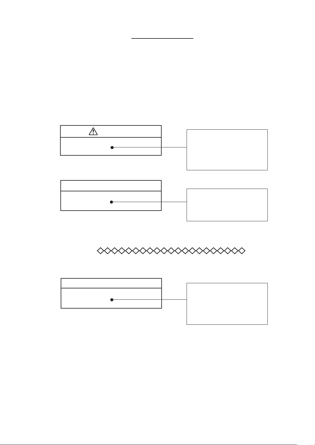
In this manual, important safety instructions are specially marked as shown
below. To prevent the risk of death or injury to persons and severe damage
to the unit or peripheral equipment, make sure that all instructions are fully
understood and observed.
Caution
Important
Note
Disregarding instructions
printed here incurs the risk of
injury to persons and/or dam-
age to peripheral equipment.
Disregarding instructions
printed here incurs the risk of
damage to the product.
Contains special information
that is helpful in utilizing the
features of the unit, but that is
not directly related to safety.
iii
Page 6
Caution
When using earphones, beware of excessive volume levels
When connecting earphones to the Monitor Out connector of this unit, use
only earphones with a volume adjustment function, because there is a risk
of excessive volume levels.
Do not play the supplied disc in a CD player
The supplied viewer software installation disc is not a music CD. Inserting
this disc in a CD player poses the risk of excessive volume levels that can
cause hearing damage and damage to the CD player.
Be careful around rotating machinery
When using the unit near rotating machinery, take care that cables cannot
be caught in the machinery.
Avoid excessive force and abrupt operation
Applying strong force to the keys or card slot cover of the unit can lead to
damage and injury. When connecting or disconnecting cables and opening
or closing the card slot cover, take care not to pinch your ngers.
iv
Page 7

Important
Check the install CD before installation
Before inserting the supplied viewer software install CD in the CD-ROM
drive of a computer, be sure to visually check the disc. If there are any cracks
or scratches or if the disc is deformed, do not insert the disc in the CD-ROM
drive. Otherwise there is a risk of damage to the CD-ROM drive.
Handle batteries correctly
If batteries are inserted with wrong polarity or otherwise mishandled, battery
uid may leak and overheating may occur.
Do not apply excessive voltage
Make sure that voltage applied to the power supply connector (DC IN), to the
Input connectors, and to the external trigger (Ext. Trig.) connector does not
exceed the speci ed values. Otherwise there is a risk of damage to the unit.
v
Page 8
Usage Precautions
Operate the unit only as described in this manual.
Observe the following conditions with regard to locations for use and
storage of the unit:
• Do not use or store the unit in locations where the speci ed permis-
sible range for temperature and humidity may be exceeded (-10ºC to
+50ºC, max. 90% RH).
• Do not use or store the unit in locations where there are rapid and
drastic changes in temperature or where there is a possibility of con-
densation.
• Do not use or store the unit in locations that may be subject to splashes
of water or other liquids.
• Do not use or store the unit for an extended time in locations that may
be exposed to direct sunlight.
• Do not use or store the unit in locations that may be subject to air
with high salt or sulphur content, or subject to the in uence of gases
and other chemicals.
• Do not use or store the unit in slanted or instable locations.
• Do not use or store the unit in locations that may be subject to vibra-
tions or shock.
If batteries are inserted with wrong polarity or otherwise mishandled,
battery uid may leak and overheating may occur.
Make sure that voltage applied to the power supply connector (DC IN)
and to the signal Input connectors does not exceed the speci ed values.
Take care that cables and other parts cannot be caught in rotating ma-
chinery.
Do not apply strong force to the keys or card slot cover of the unit. Oth-
erwise there is a risk of damage to the unit or injury to ngers etc. When
connecting or disconnecting cables and opening or closing the card slot
cover, take care not to pinch your ngers.
Use only earphones with volume control function at the Monitor Out
connector of this unit, and beware of excessive volume levels.
vi
Use only SD memory cards supplied by Rion. Other commercially avail-
able cards may not operate properly with the unit.
Page 9

Verify before use that all cables are correctly and safely connected. Do not
bend cables sharply or subject them to pressure. When removing cables,
always grasp the plug or connector and do not pull the cable.
Do not apply strong shock to the connected cables to the unit. Otherwise
the cables may remove from the unit.
If it starts raining while using the unit outside, stop the measurement and
protect the unit from getting wet. In case the unit gets wet, wipe it with
a dry cloth and let it dry in a well-ventilated place.
Always turn the unit off after use. Remove the batteries from the unit
if it is not to be used for a long time. Otherwise battery uid may leak,
posing a risk of corrosion and damage. Also disconnect the AC adapter
or battery pack.
Do not tap the LCD panel or other surfaces of the unit with a pointed
object such as a pencil, screwdriver, etc.
Take care that no conductive objects such as wire, metal scraps, conductive
plastics etc. can get into the unit.
Do not disassemble the unit or attempt internal alterations. In case of
malfunction, do not attempt any repairs. Note the condition of the unit
clearly and contact your supplier.
Clean the unit only by wiping it with a soft, dry cloth or, when necessary,
with a cloth lightly moistened with water. Do not use any solvents, cleaning
alcohol or chemical cleaning agents.
When returning the unit for maintenance or servicing, use the original
packing to protect it from shocks and vibration.
The life of the backup battery for the internal clock of the unit is lim-
ited. You should have the battery replaced about once every ve years.
Regarding replacement of the battery, please contact your supplier.
Please note that this product is warranted up to the product purchase price
against defects in material.
Dispose of the unit and of batteries only according to national and local
regulations at the place of use.
vii
Page 10
AC adapter precautions
Use only the speci ed AC adapter available as an option for the DA-21
(NC-98C). Use of any other adapter can lead to damage or unexpected
accident. Take care not to mix up the AC adapter with the AC adapter of
another product.
Open source software
This product contains the open source software of the following licenses.
(1) GPL
(2) GPL v 2
(3) GPL v 3
(4) Boost Software License
Those source codes of the open source software according to the li-
cense agreement will be given. Those source codes are available for
download from the Rion Support Room (http://svmeas.rion.co.jp/).
Note that we assume no responsibility for the source code.
Note that we are not responsible for exact details of the source code.
For details on the license, click [Manual] - [Open Source License]
folder in the supplied CD-ROM.
viii
Page 11

Contents
FOR SAFETY ............................................................................... iii
Outline ............................................................................................1
Controls and Functions ....................................................................5
Front panel .................................................................................5
Rear panel ................................................................................10
Right side panel .......................................................................12
Bottom panel ...........................................................................13
Power On/Off ................................................................................14
Display Explanation ...................................................................... 17
Display screen..........................................................................17
Menu Operations and Setting Items ..............................................30
General menu operation steps ..................................................30
Menu Items ..............................................................................39
<Input> menu .....................................................................39
<Rec.Parameters> menu .....................................................44
<Trigger> menu..................................................................46
<Bar Graph> menu .............................................................50
<System> menu ..................................................................51
<Synchronization> menu ....................................................55
Preparations ..................................................................................56
Preparations and checks before recording ................................57
Power supply ......................................................................57
SD memory card preparations ............................................ 61
External equipment (sensor etc.) connections .....................64
Input settings ......................................................................65
Recording parameter settings ...................................................70
Input range setting ..............................................................70
Sampling ............................................................................73
Recording process .............................................................. 74
Auxiliary function setup ..........................................................84
Device index number (<System> menu: Index) ...................84
Voice memo/marker ...........................................................85
ix
Page 12

Preventing inadvertent operation (key lock and menu lock) 87
Remote control operation ...................................................89
Connection to a computer .......................................................90
Inter-unit synchronization ........................................................ 91
Tachometer signal input ...........................................................93
Recording ......................................................................................94
Recording steps .......................................................................94
1. Checks before recording ......................................................94
2. Input range setting / Calibration signal recording ................96
3. Recording ............................................................................98
Using the voice memo/marker function .................................. 102
Data recording example .........................................................105
Recall/Playback of Recorded Data .............................................. 108
Activating recall mode ...........................................................108
Playback of recorded data ...................................................... 111
Canceling recall mode ........................................................... 115
Other information .................................................................. 115
Messages ..................................................................................... 119
Filter Characteristics ...................................................................128
Settings and Other Information ...................................................129
Approximate recording times ................................................129
Menu items ............................................................................130
Data recording .......................................................................133
Representative value of inherent noise ...................................138
Power save settings ................................................................ 138
WAVE File Format ...................................................................... 139
Basic structure ....................................................................... 139
Basic WAVE le structure ................................................ 139
File structure and size ...................................................... 140
Invalid values ......................................................................... 141
Data types .............................................................................. 142
Chunks .................................................................................. 143
Speci cations .............................................................................. 152
x
Page 13
Outline
The DA-21 is a compact, lightweight data recorder designed for waveform
recording. The unit can be powered from batteries, for convenient use in the
eld.
To record sound or vibration waveforms, microphones or accelerometers can
be connected easily. The capability for sensor drive power supply (CCLD) is
also provided. Unlike with conventional units having only general-purpose
connectors, the design of the DA-21 eliminates the need to set up additional
connection equipment, allowing quick and uncomplicated recording start.
Features
The unit has the following features.
Simultaneous recording of electrical signals in up to 4 channels.
Compact and lightweight body ensures easy portability. A set of four
IEC LR6 (size AA) alkaline batteries will power the unit for about
8 hours of continuous use (at 23ºC, frequency range setting 100 Hz,
4-channel input, CCLD off, backlight off).
CCLD support allows easy hookup of sensors including microphones
and accelerometers.
A wide range of sensors for converting sound pressure, vibrations,
rotation, temperature or other measurement quantities into an electrical
signal (AC or DC) is supported. Measurement quantities measured
by sensors are displayed in units “V”, “V/EU”, “mV/(m/s2)” or “dB”
with a user selectable setting range.
Frequency range from DC to 20 kHz allows recording of a wide range
of phenomena.
Recorded data are stored on SD memory card in WAVE format. For
example, when using a 32 GB card, available recording time with the
20 kHz frequency range setting and continuous recording in 4 input
channels is about 23 hours.
Voice memo and marker information can also be recorded, to facilitate
later data management.
1
Page 14

Outline
Accurate playback of data is possible, making it easy for example to
check the reliability of data in the eld. The playback signal can also
be output to an analyzer or similar equipment.
Supplied viewer software (AS-70 Viewer) for use on a computer
provides the required features for checking and storing the recorded
waveform data (including voice memo and marker), as well as fre-
quency weighting and time weighting functions. The software runs
on Windows computers.
Synchronize two DA-21 units to record signals simultaneously up to
8 channels.
2
Page 15
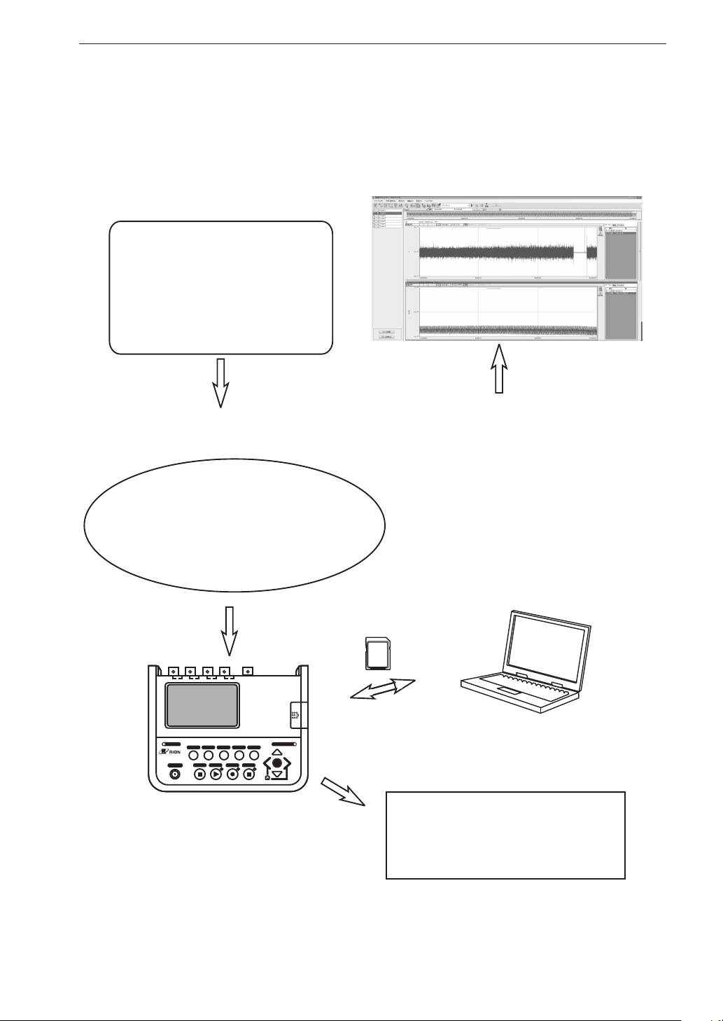
System con guration
Target
Automobile running test
(sound and vibration data)
Road traffic noise
(sound pressure waveform data)
Product inspection data
Other data
Sensor/Measuring instrument
Sound level meterTachometer
Temperature meter
Microphone Accelerometer
Other sensor
Vibration level meter
Analysis
Application software
Supplied: Viewer software
Optional:
Waveform analysis software CAT-WAVE
(The version corresponding to DA-21
is required. )
Waveform analysis software AS-70
Generic waveform processing software
(up to 2 channels)
(NOTE)
WAVE files created by the DA-21 are not
supported by the DA-20PA1, DA-40 Viewer
or CAT-78WR application software.
Outline
1
2
3
4
CARD
OVERLOAD
DA-21
4ch DATA RECORDER
POWER
LIGHT RECALL RANGE
CLEAR Ov
STOP PLAY REC PAUSE
CARD CAPACITY
MENU
ENT
4 Channel Data Recorder
DA-21
SD memory card
Playback signal
monitoring output
Waveform monitoring equipment
Windows Computer
(generic)
Voltmeter
FFT analyzer
Other equipment
3
Page 16
Outline
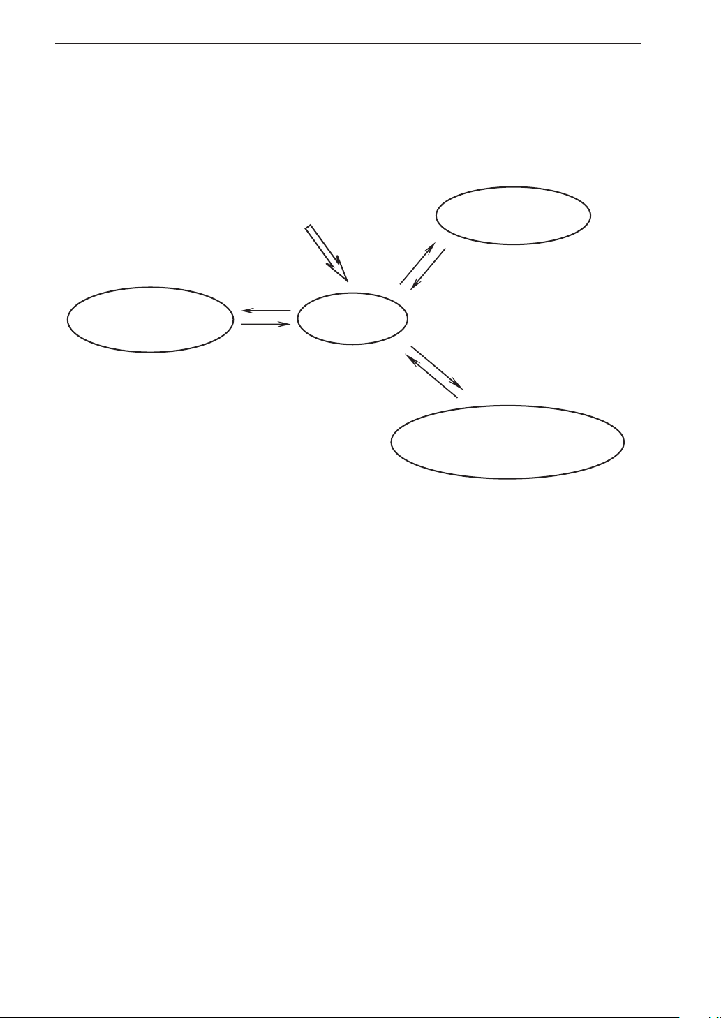
Operation environment
The DA-21 allows various operations for recording data. The general concept
of the basic functions is as shown in the diagram below.
Menu screen
(for changing settings)
Main screen This screen appears as the rst screen, a short
Power ON
[MENU]
[MENU]
or [STOP]
Recording procedure
(record data)
[REC]
Recording end
or [STOP]
Main screen
[RECALL]
[RECALL]
Recall mode
(for processing of recorded data)
while after power to the unit is turned on. The
menu screens, recording procedure, and recall
mode are all accessed from the main screen. Input
range selection is also possible from this screen.
Menu screen Pressing the [MENU] key at the main screen brings
up a menu screen. There are a number of menu screens
that give access to recording parameters, input settings,
and various other settings (see page 30).
Recording procedure Pressing the [REC] key at the main screen initiates
the recording procedure. This encompasses all
steps required to record data (see page 94).
Recall mode Pressing the [RECALL] key at the main screen acti-
vates the recall mode. In this mode, you can check,
playback and delete recorded data (see page 108).
4
Page 17
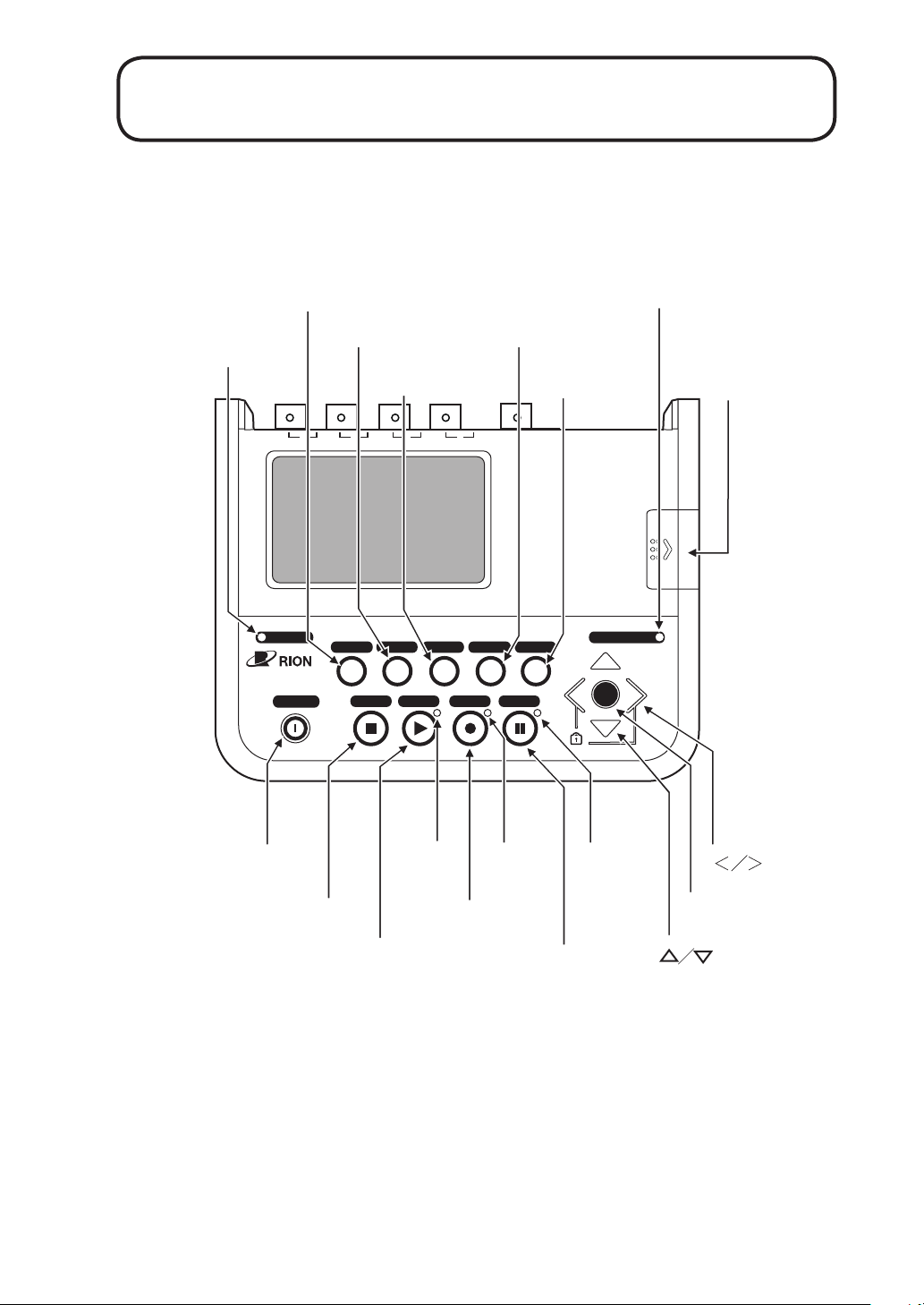
Controls and Functions
Front panel
OVERLOAD
indicator
DA-21
4ch DATA RECORDER
(9) LIGHT key
(10) CLEAR Ov key
1
OVERLOAD
POWER
LIGHT RECALL RANGE
(12) RANGE key
(11) RECALL key
2
3
4
CLEAR Ov
STOP PLAY REC PAUSE
CARD CAPACITY indicator
(13) MENU key
MENU
CARD CAPACITY
ENT
Card slot cover
CARD
(1) POWER key
(2) STOP key
PLAY
indicator
(3) PLAY key
REC
indicator
(4) REC key
PAUSE
indicator
(5) PAUSE key
(6)
(8)
(7) ENT key
key
key
5
Page 18

Controls and Functions
Display panel
Shows input data, recorded data, menus for changing settings, etc.
Key names and functions
The DA-21 has some dedicated keys that perform only a speci c function,
and some keys that perform various functions depending on the current
operating state.
(1) [POWER] key
Serves to turn the unit on and off. The key must be kept depressed for
about 2 seconds.
(2) [STOP] key
Serves to stop data recording or data playback. The key is also used for
menu operations and other functions.
(3) [PLAY] key
Serves to start data playback.
(4) [REC] key
Serves to start data recording.
(5) [PAUSE] key
Serves to pause and resume data playback.
(6) [ ]/[ ] keys
These keys serve to switch the input range, select a monitor channel, and
perform menu operations.
(7) [ENT] key
This key serves to con rm an item to be changed and accept a setting
that has been made. It is used when setting the input range, performing
menu operations, etc.
(8) [<]/[>] keys
These keys serve to change the data display format, change the le num-
ber, perform fast reverse/forward during playback, and perform menu
operations.
6
Page 19
Controls and Functions
(9) [LIGHT] key
Serves to control backlighting of the LCD screen. The backlight is turned
on or off depending on the key press timing. When the LCD backlight
has been activated, it will automatically turn itself off if there has been
no key activity for a certain period. (The duration of this period can be
changed with a menu setting.)
Note
When the remaining battery capacity is low and the
battery icon (page 23) is ashing, the backlight does
not operate.
(10) [CLEAR Ov] key
Ser ves to clear the overload history display. This display indicates if there
has been any overload condition between the point when the key was last
pressed and the current time (see page 24).
(11) [RECALL] key
Ser ves to activate the reca l l mode and to cancel the recall mode and ret u r n
to the main screen.
(12) [RANGE] key
Serves to activate and cancel the input range setting condition. In recall
mode, the key serves to delete the recording data selected by cursor.
(13) [MENU] key
Serves to bring up a menu screen or return to the main screen.
There are a number of menu screens which allow changing the settings of
the unit. Menu screens are organized by function category, such as input
settings, recording parameters, etc.
Key lock
Pressing and holding the [<] and [>] keys together for a few seconds ac-
tivates the key lock condition. In this condition, all keys except the [<]/
[>] keys and the [LIGHT] key are inactive. The condition is indicated by
a key lock icon that appears on the display (page 87).
To cancel the key lock condition, press and hold the [<] and [>] keys
together once more.
7
Page 20
Controls and Functions
Indicator names and functions
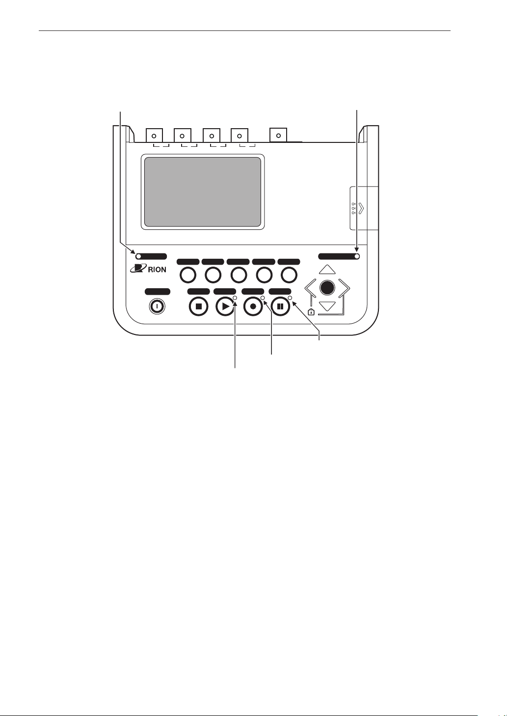
(1) OVERLOAD indicator
1
OVERLOAD
DA-21
4ch DATA RECORDER
POWER
2
3
4
LIGHT RECALL RANGE
CLEAR Ov
STOP PLAY REC PAUSE
(3) REC indicator
(2) PLAY indicator
(5) CARD CAPACITY indicator
CARD
MENU
CARD CAPACITY
ENT
(4) PAUSE indicator
(1) OVERLOAD indicator
Indicates that the input signal level in a channel is excessive. While the
indicator is lit, correct recording is not possible for that channel.
Lit in red: While the input signal is causing overload and for 1 second
after the overload condition ceases, the indicator is lit.
(2) PLAY indicator
Indicates that recorded data are being played back.
Flashing in green: Recorded data are being played back.
(3) REC indicator
Indicates the operating condition during data recording.
Flashing in red: Data are being recorded.
Flashing in green: Unit is in trigger standby condition.
8
Page 21
Controls and Functions
(4) PAUSE indicator
Indicates that data playback is being paused.
Flashing in blue: Data playback is being paused.
(5) CARD CAPACITY indicator
Indicates that the remaining data recording time on the SD memory card
is less than 10 minutes.
Flashing in red: Data recording will stop within 10 minutes.
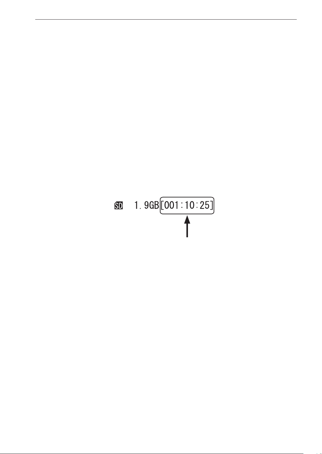
Also while the indicator is not ashing, the currently available recording
time is shown on the display in the format “XXX:XX:XX”. Before starting
to record, you should check this indication to make sure that the intended
data can be recorded. If the remaining recording time will be about 10
seconds, recording stops.
Display example for available recording time shown on the second line
from the bottom of LCD screen (Hours : Minutes : Seconds)
9
Page 22
Controls and Functions
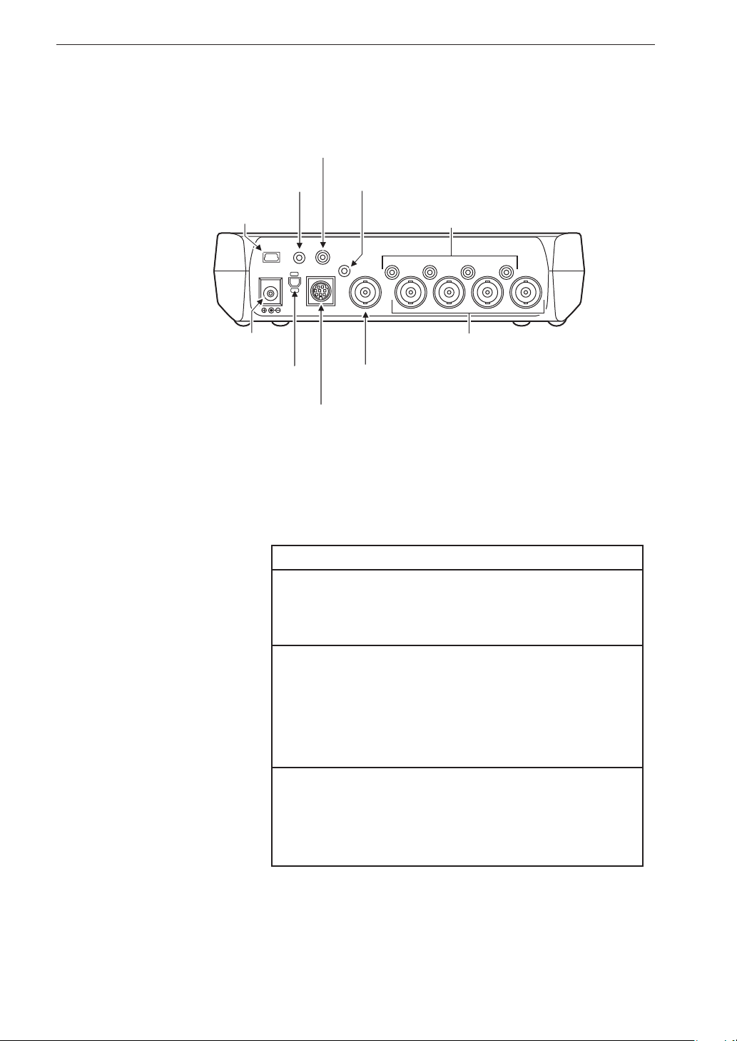
Rear panel
(8) Ext. Trig. connector
(9) Voice Input connector
(10) USB port
Voice
Input
USB
DC IN 5-20V
Sync.
(1) DC IN connector
(2) Unit to Unit connector
(7) Monitor Out connector
Ext. Trig.
Monitor
Out
Tacho
4
Remote Controller
(4) Rotary pulse input connector
(6) Output connectors
Output
2
3
1
(5) Input connectors
Input
(3) Remote Controller connector
(1) DC IN connector
The optional AC adapter NC-98C or the optional car battery adapter CC-
82 can be connected here.
Important
Do not connect any AC adapter or car battery
adapter except for the speci ed models. Otherwise the unit may be damaged.
10
The optional car battery adapter is only for
use in cars with a 12-V electrical system. If the
adapter is used in a car with a 24-V electrical
system to su p ply power to the DC IN connector
of the unit, the unit will be damaged.
When c o nnecting an exter nal DC source to the
DC IN connector, pay close attention to voltage
rating and polarity. The allowable voltage range
is 5 V to 20 V.
(2) Unit to Unit connector
Use this connector to synchronize two DA-21 units.
Page 23

Controls and Functions
(3) Remote Controller connector
Serves to connect the optional remote controller.
(4) Rotary pulse input connector
A rotary pulse signal (Tacho signal) of a fan, a motor etc. can be input here.
(5) Input connectors
These connectors are used to supply the input signal for recording.
(6) Output connectors
While recorded data are being played back in recall mode, the playback
signal is available at these connectors.
(7) Monitor Out connector
The input signal or playback signal of the channel selected for monitor
operation is output from this connector.
(8) Ext. Trig. connector
Accepts an external trigger signal.
(9) Voice Input connector
Serves to connect the optional microphone for the voice memo function.
(10) USB port
Serves for connection to a computer.
11
Page 24
Controls and Functions
Right side panel
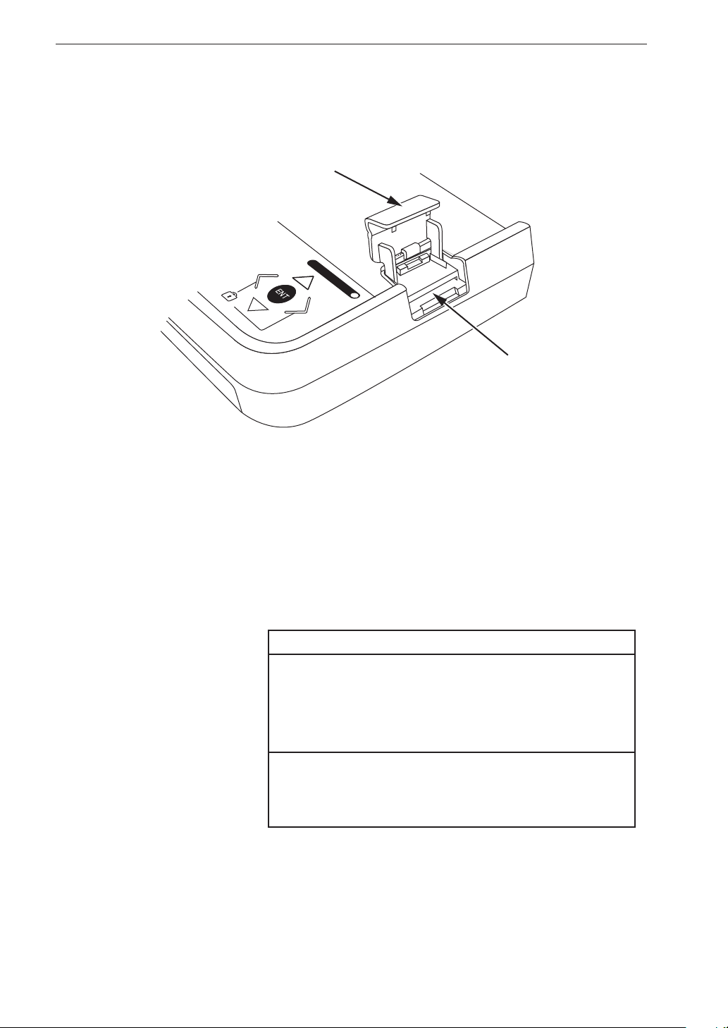
Card slot cover
CARD CAPACITY
Card slot
Card slot cover
Open this cover to access the SD memory card slot.
Card slot
The SD memory card is inserted here. The card allows storing data and
exporting data to a computer. The card slot is also used for upgrading
the system rmware etc.
Note
Use only RION supplie d SD memory ca rds cer ti ed
for operation in the DA-21. This unit supports SD
memory cards and SDHC memory cards, but not
SDXC memory cards.
When an SD memory card with a large number of
les is inserted in the DA-21, the unit may take some
time to recognize the card.
12
Page 25
Bottom panel
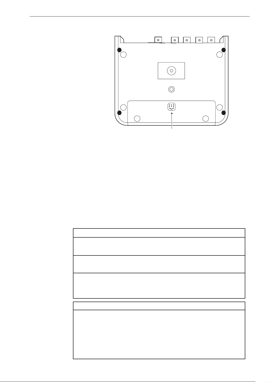
Battery compartment
Accepts four alkaline batteries (IEC LR6 [size AA]).
Menu lock mode (see page 88):
When the [MENU] switch inside the battery compartment is set to
“LOCK”, changing settings and deleting data via the menus is not possible.
Controls and Functions
Battery compartment
Wake-up-on-power mode (see page 60):
When the [WAKE UP ON POWER] switch inside the battery compartment is set to “ON”, the unit is switched on and off in conjunction
with the power supplied to the DC IN connector on the DA-21. In this
case, the [POWER] key has no effect.
Important
Take care not to reverse the (+) and (-) polarity when inserting
the batteries (see page 57).
When using the wake-up-on-power mode, there should be
no batteries inserted in the unit.
Remove the batteries from the unit if it is to be stored for
a long time with the [POWER] key set to OFF to prevent
possible damage caused by battery leakage.
Note
Before changing the position of these switches, disconnect any external power that is being supplied to the DC IN connector and remove
all batteries from the battery compartment. Otherwise operation of
the unit will become unstable. If this has happened (not a defect of
the unit), disconnect the external power, remove all batteries, after
a few seconds, reconnect the power and turn the unit on.
13
Page 26
Power On/Off
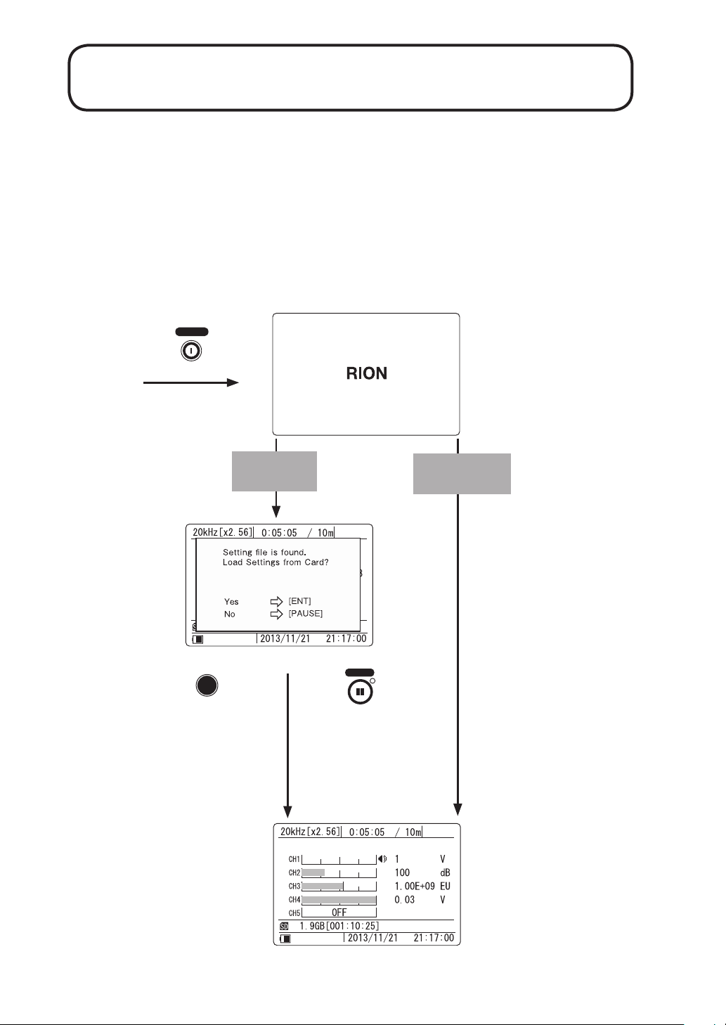
Turning the power on
When you keep the [POWER] key depressed, the startup screen as shown
below appears on the display. After a while, the main screen will be shown.
If there is a setting le on the SD memory card, the main screen does not
appear straight away. Instead, a message screen is shown asking whether
you want to load the settings from the card, or use the settings that were
established before power was last turned off.
POWER
Setting le
found
Message screen
ENT
Contents of
setting le are
loaded.
DATA RECORDER
DA-21
RION CO., Ltd.
Startup screen
No setting le
found
PAUSE
Settings that were
active before power was last turned
off are established
again.
14
Main screen
Page 27
Power On/Off
Note
The input range and menu settings etc. at power-on
will be the same as the settings that were active
before the unit was last turned off.
When the contents of a setting le are loaded at
power-on, a channel selected for CCLD will be
suppl ied with constant cu r rent. To prevent problems
due to unsuitable connections, it is recommended
to disconnect sensors before loading a setting le.
Turning the power off
When you keep the [POWER] key depressed, the shutdown screen as shown
below appears on the display, and the unit is turned off.
Shutdown screen
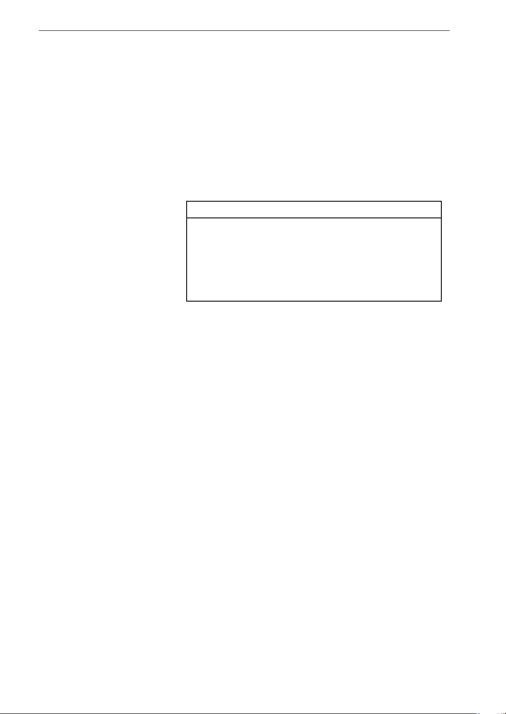
Note that if a
icon is shown at the bottom of the display, the operation
keys including the [POWER] key are locked. The power cannot be turned
off in this condition. (For information on the key lock feature, see page 87.)
Indicates the key lock condition
Note
After turning the unit off, do not turn the unit on
again immediately. Wait at least a few seconds.
In ca se key lo ck i s act ivated, pressi ng and holding [POWER] key for 10 seconds or more will turn the unit off.
15
Page 28
Power On/Off
About the setting le
You can store all setting values and parameters of the unit on the SD memory
card as a setting le (DA21.INI).
This capability allows you for example to store the optimum settings for a
certain recording task and then quickly re-establish these settings at power-on.
This reduces the time required for startup and the risk of making setup errors.
To create a setting le, use the “Read / Save Settings” item on <System>
menu. (see page 51)
Note
When the contents of a setting le are loaded at
power-on, a channel selected for CCLD will be
suppl ied with constant cu r rent. To prevent problems
due to unsuitable connections, it is recommended
to disconnect sensors before loading a setting le.
16
Page 29
Display Explanation
Display screen
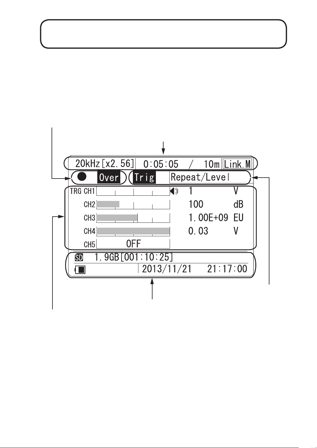
Recording/operation mode indication (page 20)
Recording parameter indication (page 18)
Channel data (page 24)
Trigger setting indication (page 21)
Status indication (page 22)
17
Page 30
Display Explanation
Recording parameter indication
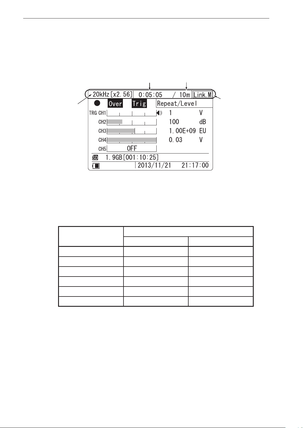
From left, the display shows the frequency range [sampling frequency], elapsed
recording time, recording time, and synchronization information.
(1) Frequency range
[Sampling frequency]
(1) Frequency range [Sampling frequency]
Shows the setting made with <Rec.Parameters> menu, items “Frequency
Range” and “Sampling Frequency”. The relationship between frequency
range and sampling frequency is as shown in the table below.
Frequency range
(2) Elapsed recording time
Sampling frequency
[×2.56] [×2.4]
(3) Recording time
(4) Synchronization
information
18
100 Hz 256 Hz 240 Hz
500 Hz 1.28 kHz 1.2 kHz
1 kHz 2.56kHz 2.4 kHz
5 kHz 12.8 kHz 12 kHz
10 kHz 25.6 kHz 24 kHz
20 kHz 51.2 kHz 48 kHz
(2) Elapsed recording time (Format: “0000:00:00”)
In recording mode, the elapsed time since the start of recording (including
pre-recording time) is displayed. The recording time indication is retained
until a new recording is started.
Page 31

Display Explanation
(3) Recording time (Format: “/ xx s [m, h]” or “/ Man”)
Shows the setting made with <Rec.Parameters> menu, item “Recording
Time”. When the manual setting has been selected, the indication shows
“/ Man”.
When the [STOP] key is pressed or the SD memory card runs out of
space, recording stops. In this case, the actual recorded data time will be
shorter than the recording time setting. (The recording time also includes
the pre-recording time of 1 second or 5 seconds.)
(4) Synchronization information
If you synchronize two DA-21 units, the unit used as master shows
“Link. M” and the unit used as slave shows “Link. S” (see page 90).
19
Page 32
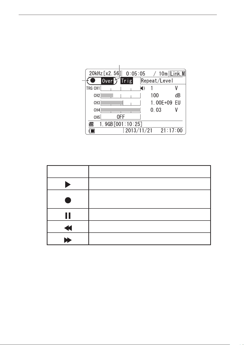
Display Explanation
Recording/operation mode indication
This eld shows recording and operation status information as well as
all-channel overload information.
(2) All-channel overload indication
(1) Recording/operation
mode indication
(1) Recording/operation mode indication
An icon indicates the current recording condition.
None Normal condition
Playback in progress (recall mode only), ashing
Recording in progress, ashing
Trigger standby, permanently on
Playback paused, ashing
Rewind (recall mode only), ashing
Fast-forward (recall mode only), ashing
(2) All-channel overload indication
This indication appears if there has been an overload condition in any
channel. There are two types of indications, for instantaneous overload
and overload history. The display method is the same as explained in
20
the section on overload information (page 24).
Page 33
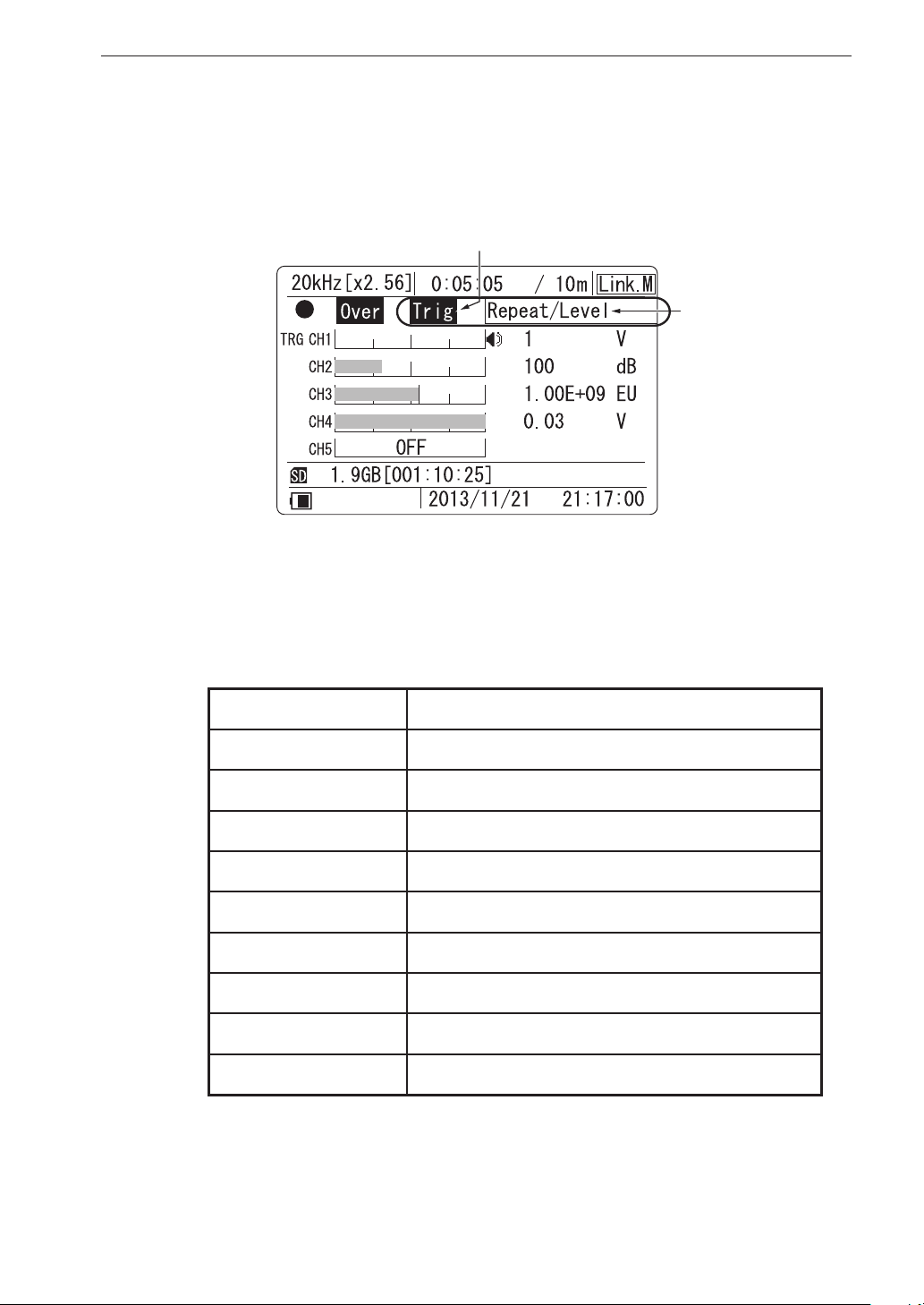
Display Explanation
Trigger setting indication
The trigger setting and type are shown here. When the trigger is set to OFF
(Free), nothing is shown.
(1) Trigger setting indicator
(2) Trigger type
(1) Trigger setting indicator
This indicator appears if any trigger (except Free) has been set.
(2) Trigger type
None Free trigger (no trigger setting)
“Single/Level” Single level trigger
“Repeat/Level” Repeat level trigger
“Single/Time” Single time trigger
“Repeat/Time” Repeat time trigger
“Single/Ext” Single external trigger
“Repeat/Ext” Repeat external trigger
“Single/Ext-Gate” Single external gate trigger
“Repeat/Ext-Gate” Repeat external gate trigger
“Master” Master trigger
When a level trigger has been set, information about the trigger channel
and trigger level is shown in the channel data area. For details on the
channel data area, see the section starting on page 24.
21
Page 34
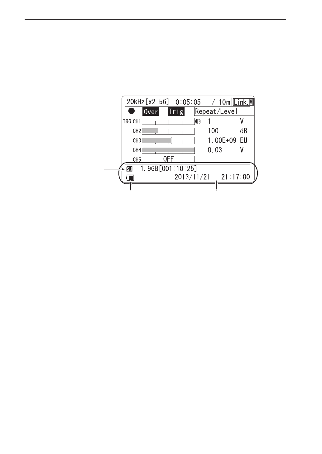
Display Explanation
Status indication
In the second line from the bottom, the display shows the card icon, card
capacity (size/available recording time), and in the bottom line, the icon and
clock (date/time).
(1) Card icon /
remaining capacity
(2) Icon
(3) Clock
(1) Card icon/remaining capacity
The remaining card capacity is shown here in data size and the remain-
ing recording time as calculated from the currently selected sampling
frequency and number of active channels.
When no card is inserted, the card icon and remaining capacity indication
are not shown, and the remaining recording time indication shows “---:--:--”.
22
Page 35
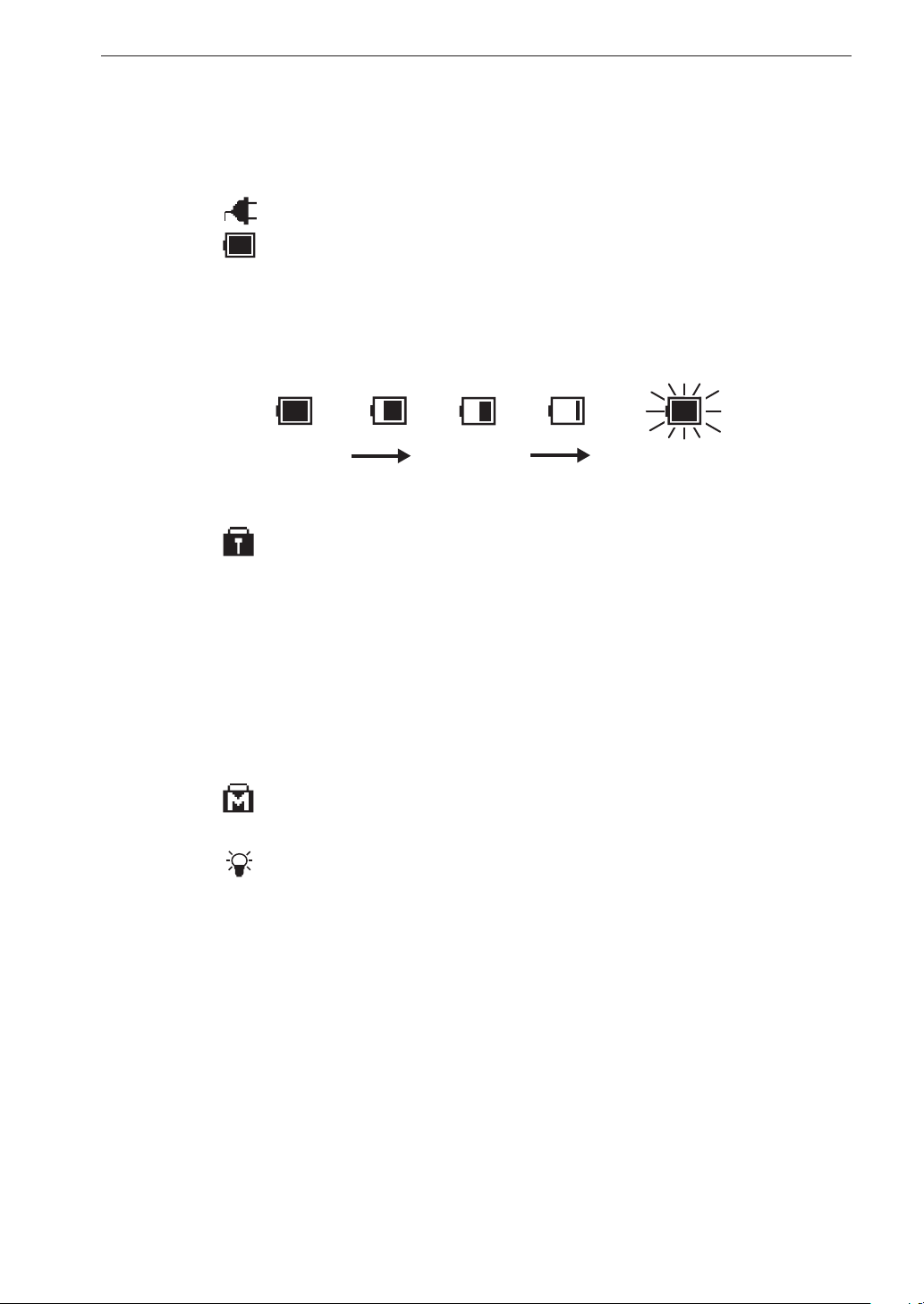
Display Explanation
(2) Icon
A graphic symbol representing the power supply status, key lock status,
or menu lock status is shown here.
: Shown when unit is being powered from an external source.
: Shows the approximate remaining battery capacity when the unit
is being powered from batteries. The number of black segments
decreases as the batteries get depleted. When the indication starts
to ash, replace the batteries with a fresh set.
Maximum
capacity
Low battery
Flashing (replace batteries)
: Indicates the key lock condition where the operation keys except
for [LIGHT], [<], and [>] are disabled. (For details on the key lock
function, see page 86.)
The condition is activated by pressing and holding the [<] and [>]
keys together for a few seconds. Repeating the procedure cancels
key lock and causes the icon to disappear.
The keys on the Remote Controller are not affected by the key
lock function.
: Indicates the menu lock condition where the menus cannot be
used. (For details on the menu lock function, see page 88.)
: Indicates the display backlight has been lit up.
(3) Clock
Shows the current date and time, using 24-hour format.
* Backlight cannot be used.
23
Page 36
Display Explanation
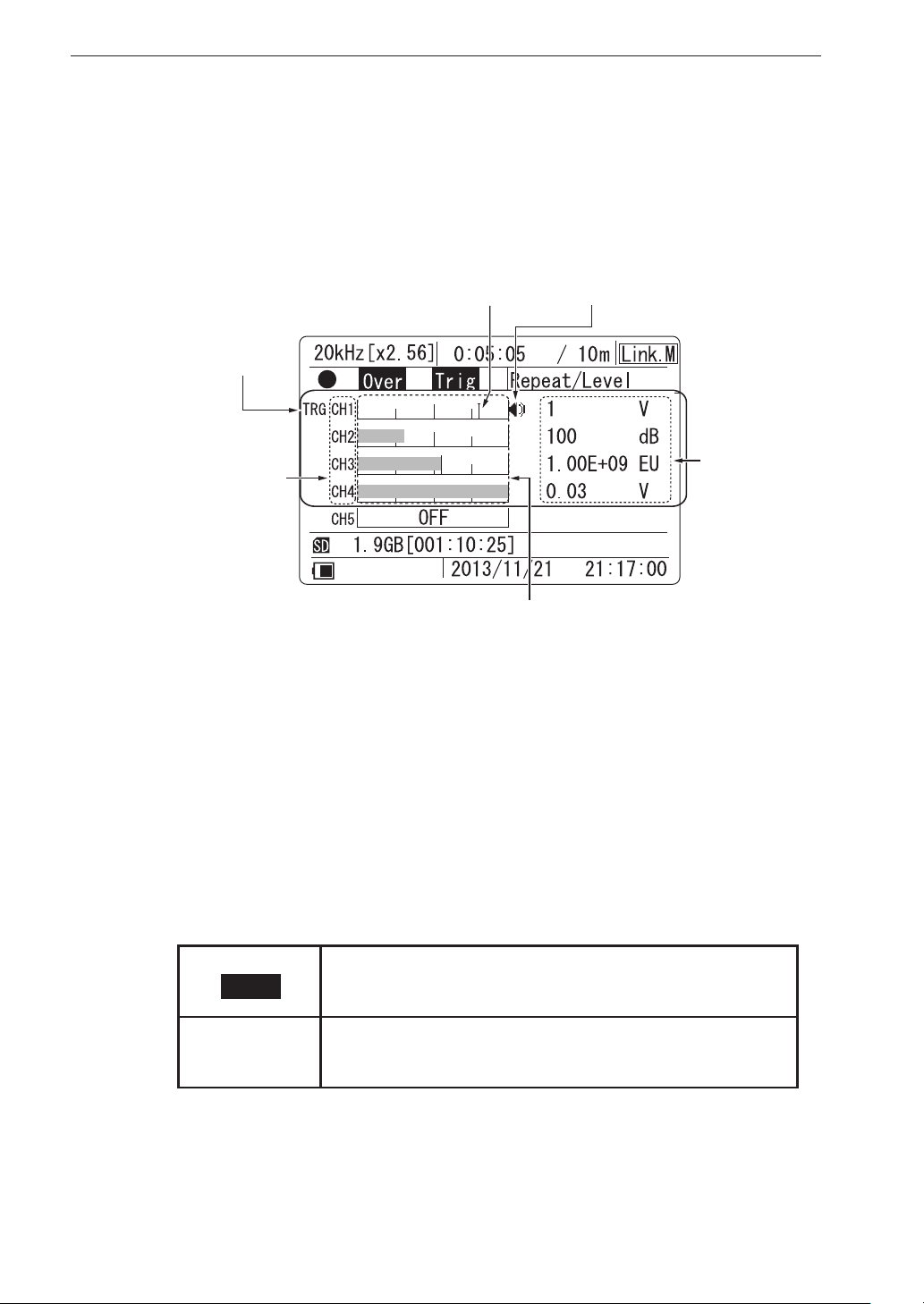
Channel data
From left, the display shows the level trigger target channel, channel number/
overload information, bar graph, trigger level, monitor icon and range full-
scale value.
The data for four channels are shown simultaneously on the display.
(4) Trigger level
(1) Level trigger
target channel
(2) Channel number/
overload information
(3) Bar graph
(1) Level trigger target channel
When the level trigger function is used, the indication “TRG” is shown
to the left of the channel indication.
(2) Channel number/overload information
The channel number (CH1 to CH4) is shown here. If an overload signal
(5) Monitor icon
(6) Range
full-scale
value
24
is input, the channel number switches to the overload information.
There are two types of overload indications: instantaneous overload and
overload history.
OVER
Shown when instantaneous overload has occurred.
Shown when overload has occurred at least once during
OVER
recording (overload history).
Page 37
Display Explanation
The overload history indication is cleared in the following cases:
• Power-on
• [CLEAR Ov] key pressed
• Recording settings changed:
• Frequency range
• Sampling frequency
• Input range
• Channel setting (type, HPF, LPF, sensor type, scaling)
• Recording start
• When recall mode is canceled
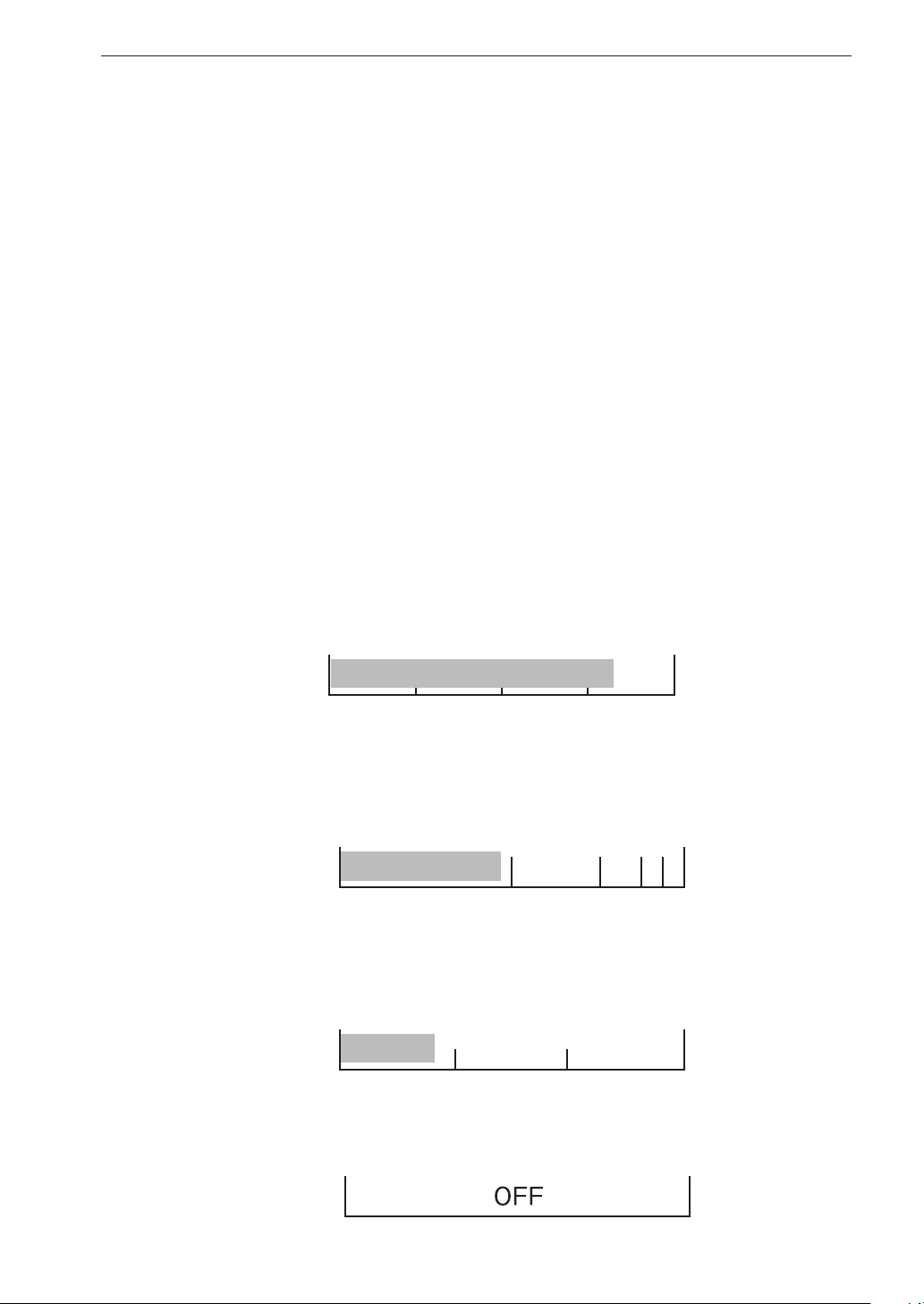
(3) Bar graph
Shows the magnitude of the input signal, using one of the following three
methods:
• Linear value display
This is used when “Linear” has b een selecte d in the <Ba r Graph > menu
(see page 50). If the sensor type for the channel has been set to “SLM/
VM” in the <I N PUT> menu (see page 39), this mode cannot be selecte d.
• Logarithmic value display (bar graph covers about 80 dB)
This is used when “L og” ha s been selected in the <Bar Graph> menu.
If the sensor type for the channel has been set to “SLM/VM”, this
mode cannot be selected.
• dB value display (bar graph covers about 80 dB)
When the sensor type for the channel has been set to “SLM/VM”, this
mode is always used, regardless of the <Bar Graph> menu setting.
• Channel OFF
This indication is shown when the respective channel is set to OFF.
25
Page 38
Display Explanation
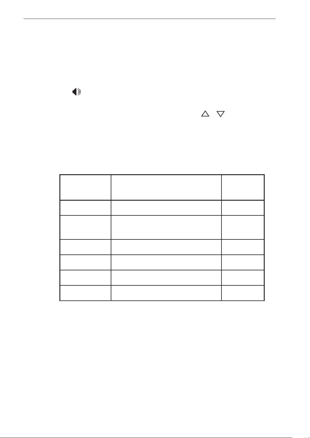
(4) Trigger level
When level trigger is used, a vertical line on the bar graph for the respec-
tive channel shows the level trigger position.
(5) Monitor icon
The icon is shown to the right of the bar graph for the channel selected
for monitor output.
The monitor channel can be changed using the [ ]/[ ] keys.
(6) Range full-scale value
Depending on the “Sens” and “Sensitivity” settings in the <Input> menu,
the value corresponding to the bar graph full range point is shown here.
A list of the menu settings and values/units is shown in the table below.
<Input> menu
Numeric range (number of digits) Unit
“Sens” setting
V 0.01, 0.03, 0.1, 0.3, 1, 3, 10 “V”
EU 9.99E ± 99 “V/EU”
MIC -0.1 to -99.9 (5 digits, 0.1 dB step) “dB”
PICK 9.99E ± 99 (8 digits) “mV/(m/s
SLM 40 to 140 (3 digits, 10 dB step) “dB”
VM 40 to 140 (3 digits, 10 dB step) “dB”
For information on changing the input range setting, see page 70.
2
)
26
Page 39
Display Explanation
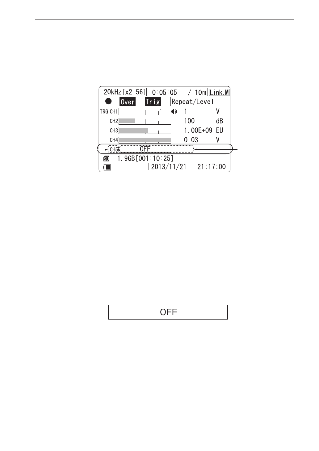
CH5 data
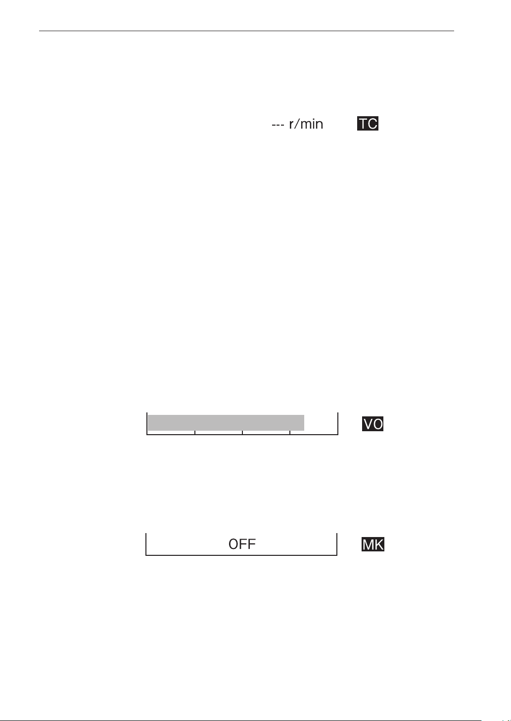
The CH5 eld either shows tachometer signal information or information
about the use of the voice memo and marker function.
(1) Channel number /
overload information
(1) Channel number/overload information
The channel number (CH5) is shown here. If an overload signal is input,
the channel number switches to the overload information (see page 24).
(2) Bar graph and setting information
Depending on the setting made for “CH5” in the <Input> menu (see page
39), the display is switched as follows.
“OFF” setting
•
“OFF” is shown in the bar graph area.
(2) Bar graph and
setting information
27
Page 40
Display Explanation
“Tacho” setting
•
The rpm value of the input tachometer signal is shown.
When “Tacho” is selected, the overload/underload evaluation conditions
are as follows.
Overload signal evaluation
• “Over” is shown when revolution speed reaches or exceeds 600,000
rpm.
• Above the upper limit of 630,000 rpm, the invalid indication “---”
is shown.
Underload signal evaluation
• “Under” is shown when revolution speed is 200 rpm or lower.
• Under the lower limit of 190 rpm, the invalid indication “---” is
shown.
“Voice Memo” setting
•
The level of the voice memo input is shown in the bar graph area.
“Marker” setting
•
“OFF” is shown in the bar graph area, and the icon ashes when the
marker function is used.
28
Page 41
Display Explanation
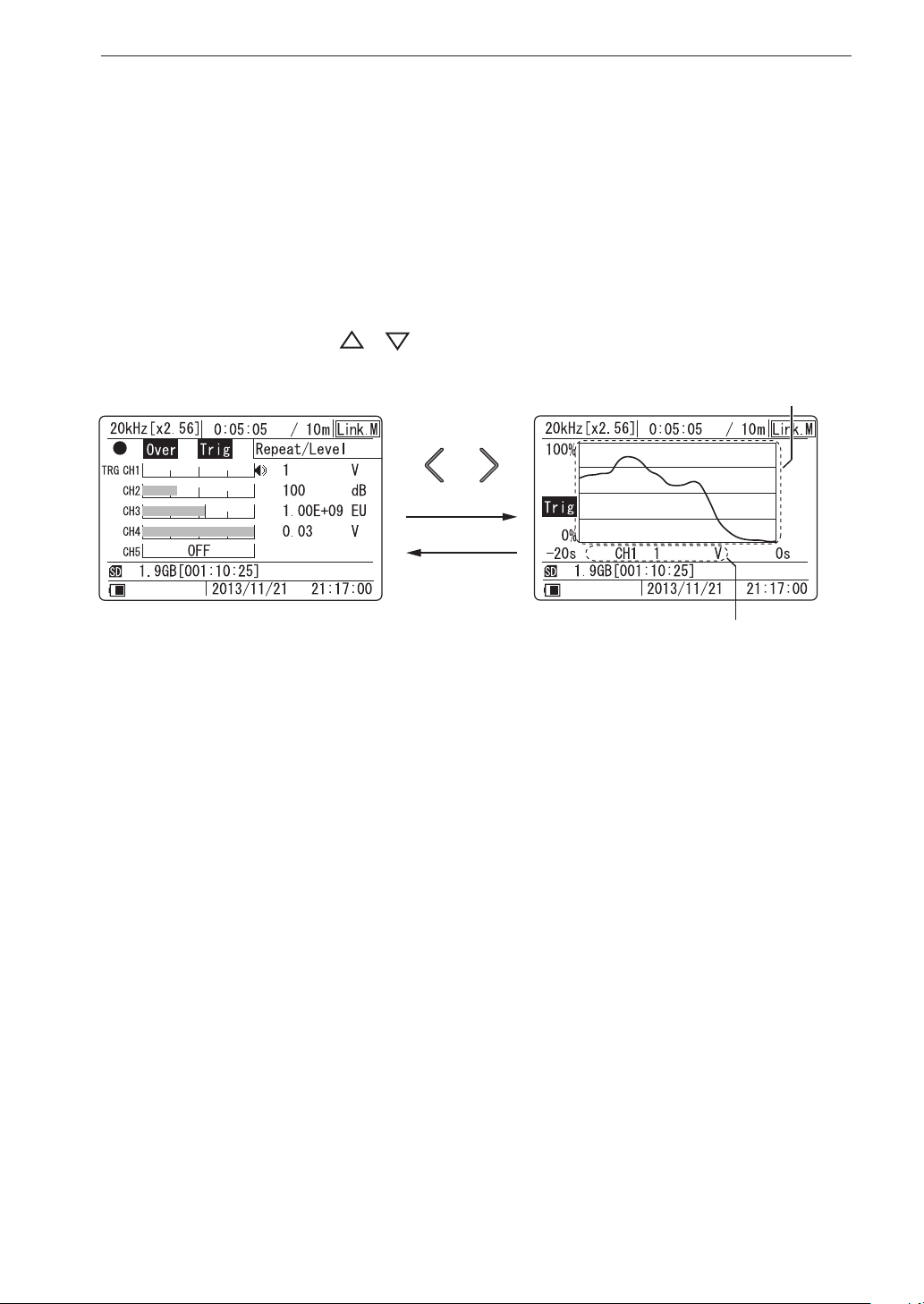
History display
Besides the bar graph format, the data display can also show a history graph
of waveform data absolute values. (This is not available in recall mode.) To
switch between the bar graph and history display, use the [>] or [<] key.
The data shown on the history display are the data of the monitor channel.
The horizontal axis is the time (up to 20 seconds before), and the vertical
axis is the level. Also during history display, you can switch the monitor
channel with the [
]/[ ] keys.
(2) Time-level graph
(1) Channel information
(1) Channel information
From left, the display shows the voice memo, tacho, or marker icon (when
channel 5 is used), the channel number, and range full-scale.
(2) Time-level graph
The time-level graph shows a history graph for waveform data of the last
20 seconds in the monitor channel.
The graph is based on the approximate absolute (not the root mean
square) values of the input waveform.
29
Page 42
Menu Operations and Setting Items
General menu operation steps
Almost all settings of the DA-21 except for the input range setting are made
via menus.
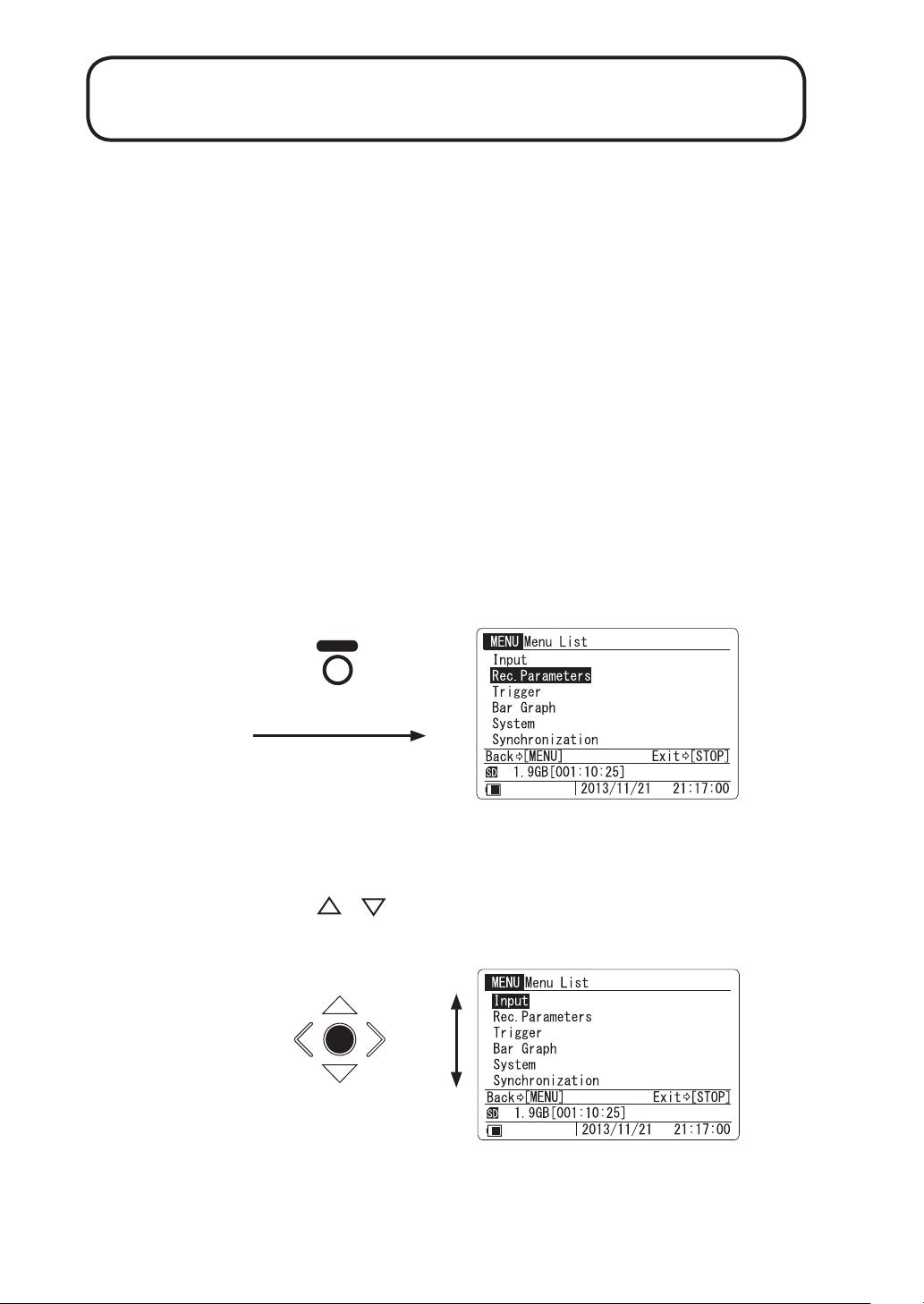
To make a setting, you call up the menu from the menu list page. When a
menu has been selected, the screen with the individual settings of that menu
appears.
There are a total of six menu pages, divided by category such as input related
settings, recording settings etc. A detailed description of menu operation
steps follows.
1. Call up the menu list
Press the [MENU] key. The menu list appears.
MENU
2. Select a menu page
Use the [ ]/[ ] keys to move the cursor to the desired menu page.
ENT
30
Page 43
3. Open the menu page
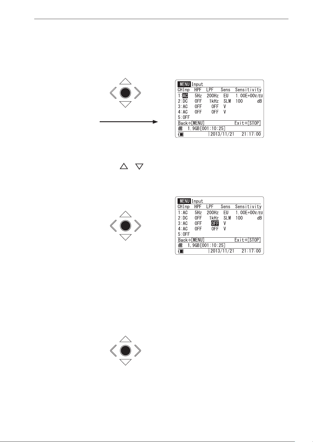
Press the [ENT] key. The items on the selected menu page appear.
ENT
4. Select an item
Menu Operations and Setting Items
Use the [
]/[ ] /[<]/[>] keys to move the cursor to the desired
setting item.
ENT
5. Initiate the change
Press the [ENT] key to start changing the selected item.
There are three ways of changing a setting, as follows.
ENT
A : Select setting item on sub menu
B : Change setting value on sub menu
C : Execute (process) selected item
31
Page 44
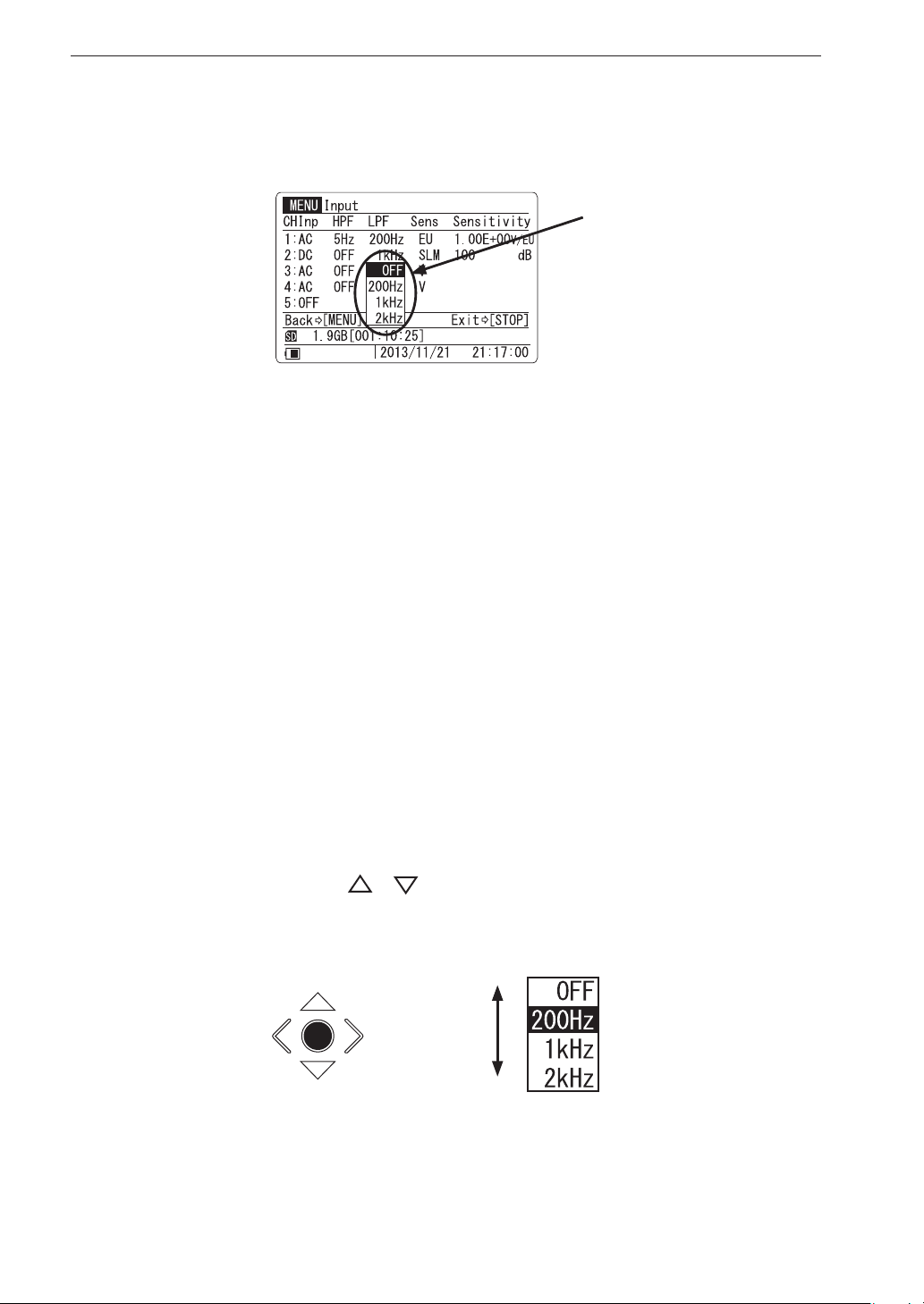
Menu Operations and Setting Items
6. Detailed explanation of methods A, B, C
A: Select setting item on sub menu
The sub menu appears when the [ENT] key is pressed. Select the
setting from the sub menu. The following setting items have this
type of sub menu.
<Input> (Sensor signal type, High pass lter, Low pass lter,
<Rec.Parameters>
Sub menu
Sensor type)
(Frequency Range, Sampling Frequency, etc.)
<Trigger> (Trigger Mode, Trigger Type, etc.)
<Bar Graph> Bar Graph Display Type
<System> (Play Signal Output, Backlight Brightness, etc.)
<Synchronization>
(Master or slave selection)
The explanation below uses the channel 3 LPF setting on the <Input>
menu as an example. The procedure is the same for other items.
A-1 Use the [
]/[ ] keys to move the cursor in the sub menu to
the desired setting.
ENT
32
Select setting
Page 45
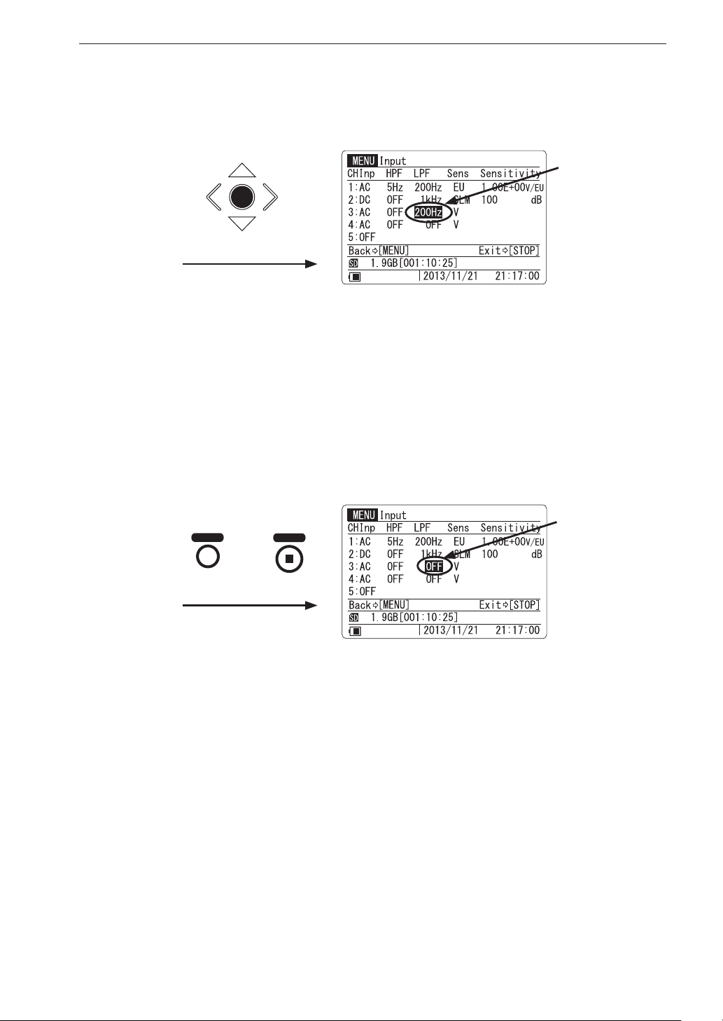
Menu Operations and Setting Items
A-2 Press the [ENT] key. The change is accepted and the sub menu
disappears.
LPF OFF setting
ENT
has changed to
200 Hz
Con rm change
A-2’ By pressing the [MENU] key or [STOP] key instead of the
[ENT] key, you can cancel the sub menu without changing the
setting. In this case, the indication is as shown below.
MENU
STOP
or
Cancel the sub menu
operation
Setting remains
OFF
33
Page 46
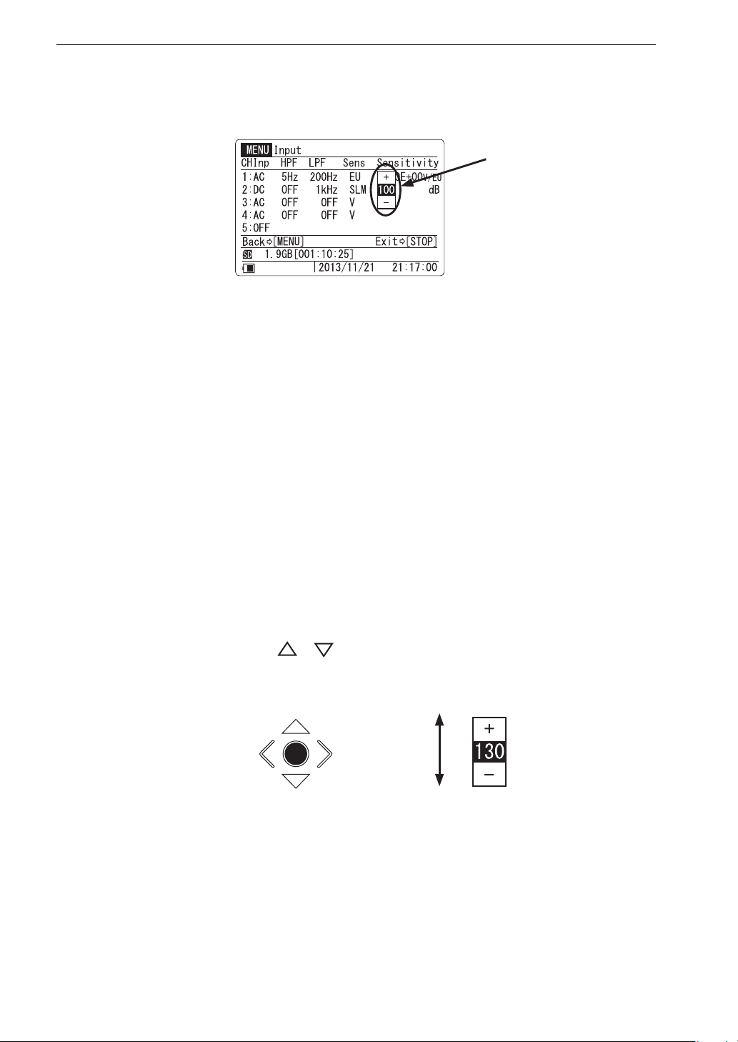
Menu Operations and Setting Items
B: Change setting value on sub menu
The sub menu appears when the [ENT] key is pressed. Change the
setting value on the sub menu. The following setting items have this
type of sub menu.
<Input> (Sensitivity)
<Rec.Parameters>
Sub menu
(Recording time, Pre-recording time)
<Trigger> (Trigger level, Recording start time, Recording
stop time)
<System> (Device index number, clock setting)
The explanation below uses the CH2 Sensitivity setting on the <In-
put> menu as an example. T he pro cedure is the same for other items.
B-1 Use the [
]/[ ] keys to change the value or unit of the item
in the sub menu. Holding down a key causes a faster change.
ENT
Change setting value
34
Page 47
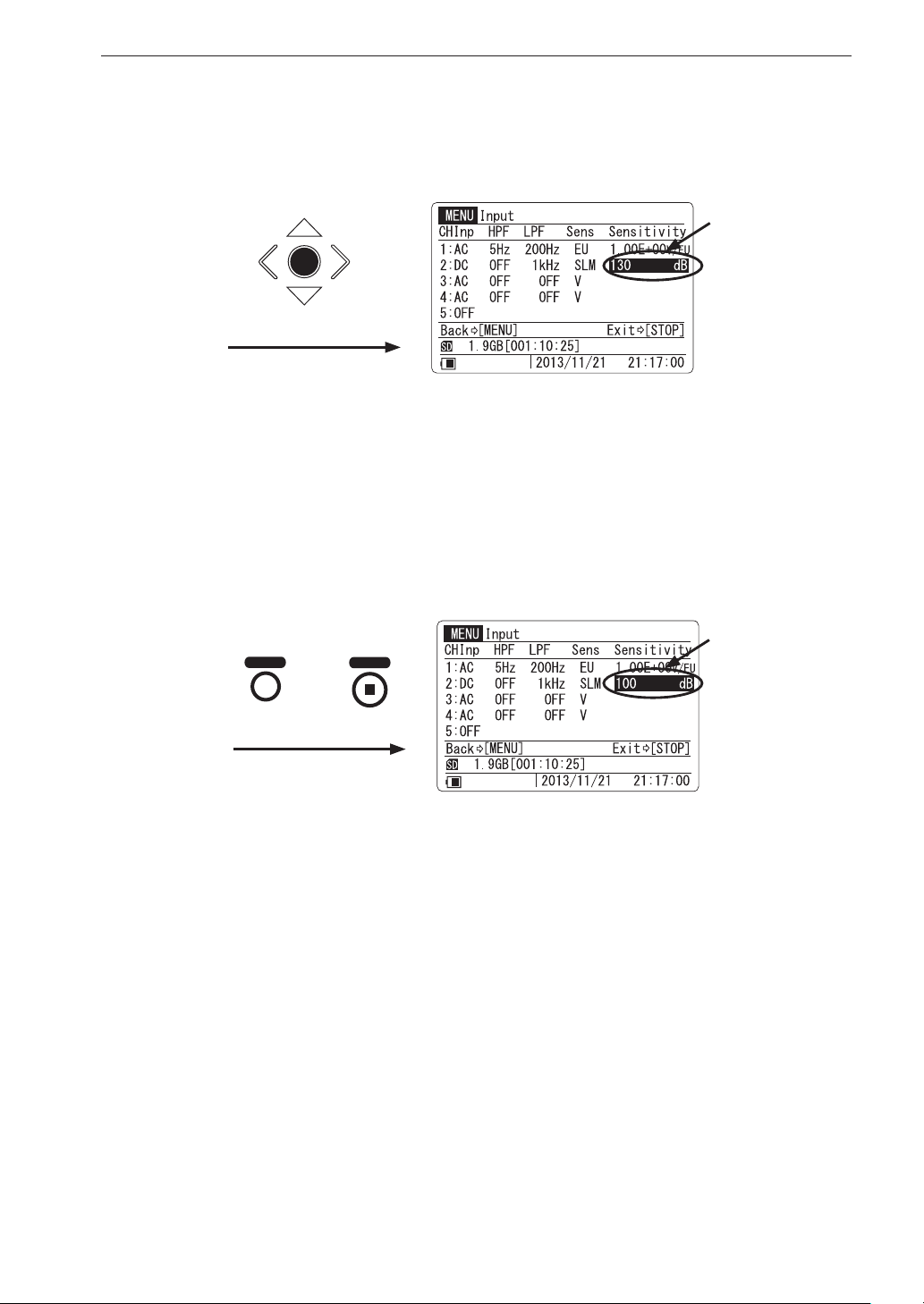
Menu Operations and Setting Items
B-2 Press the [ENT] key. The change is accepted and the sub menu
disappears.
Sensitivity set-
ENT
ting has changed
to 130 dB from
100 d B
Con rm change
B-2’ By pressing the [MENU] key or [STOP] key instead of the
[ENT] key, you can cancel the sub menu without changing the
setting. In this case, the indication is as shown below.
MENU
STOP
or
Cancel the sub menu
operation
Setting remains
100 d B
35
Page 48
Menu Operations and Setting Items
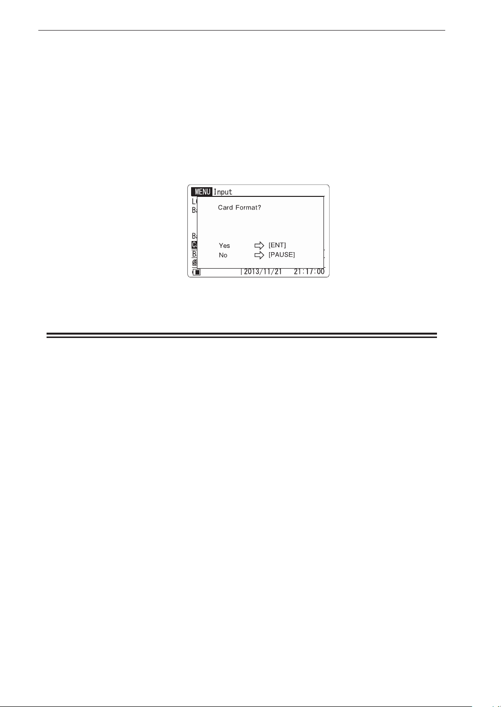
C: Execute (process) selected item
This type of setting procedure applies to items such as “Card Format”
and “Read / Save Settings” on the <System> menu. To execute the
process, press the key corresponding to “Yes”. To cancel the process,
press the key corresponding to “No”. When the process is completed,
the original menu page appears again.
Execution choice example
This concludes the description of the three ways of changing a menu
setting.
36
Page 49
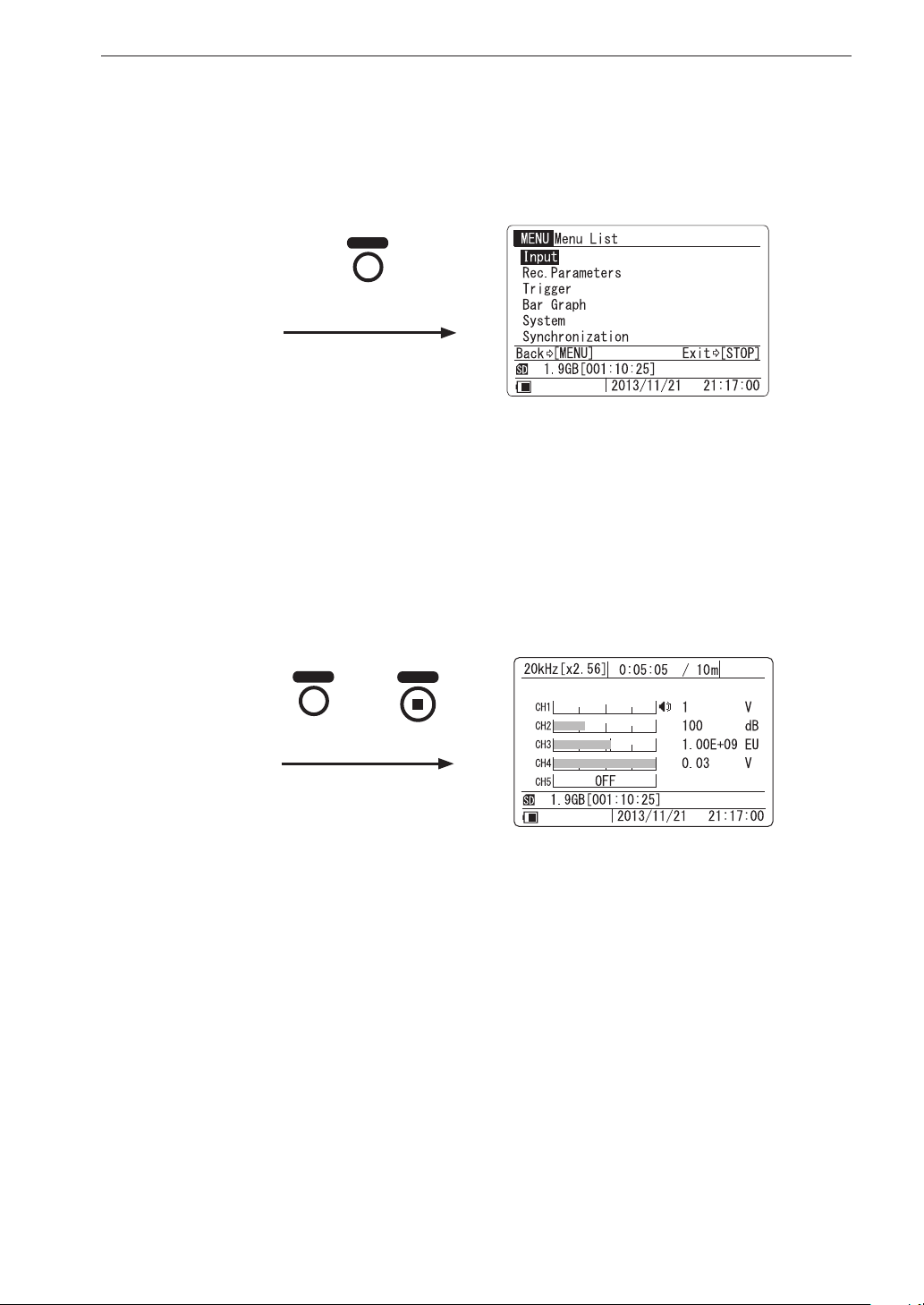
7. Changing an item on another menu page
Press the [MENU] key to bring up the menu list.
MENU
To change an item on
another menu page
8. Return to main screen
Press the [MENU] key or [STOP] key to return to the main screen.
Menu Operations and Setting Items
MENU
STOP
or
Return to main screen
37
Page 50
Menu Operations and Setting Items
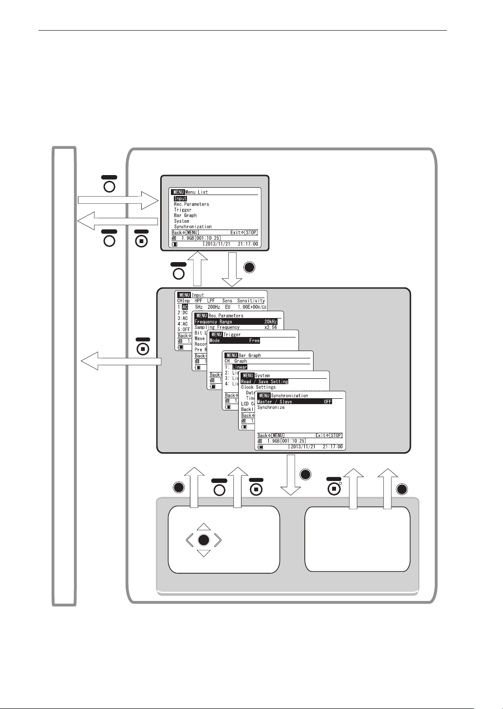
Menu ow diagram
The organization of all menu operations is shown in the diagram below. Note
that you always have to use the menu list to go to a menu page.
MENU
Menu screen
Menu list
MENU
STOP
STOP
MENU
ENT
Confirm change
MENU
ENT
Cancel
STOP
Menu pages
Only one menu page can be used
at a time. To go to another menu
page, return to the menu list first.
ENT
PAUSE
Cancel
Execute
ENT
Main screen
38
ENT
Sub menu
Execute(process)item
[Processing message]
Setting changed
/processing completed
Page 51
Menu Items
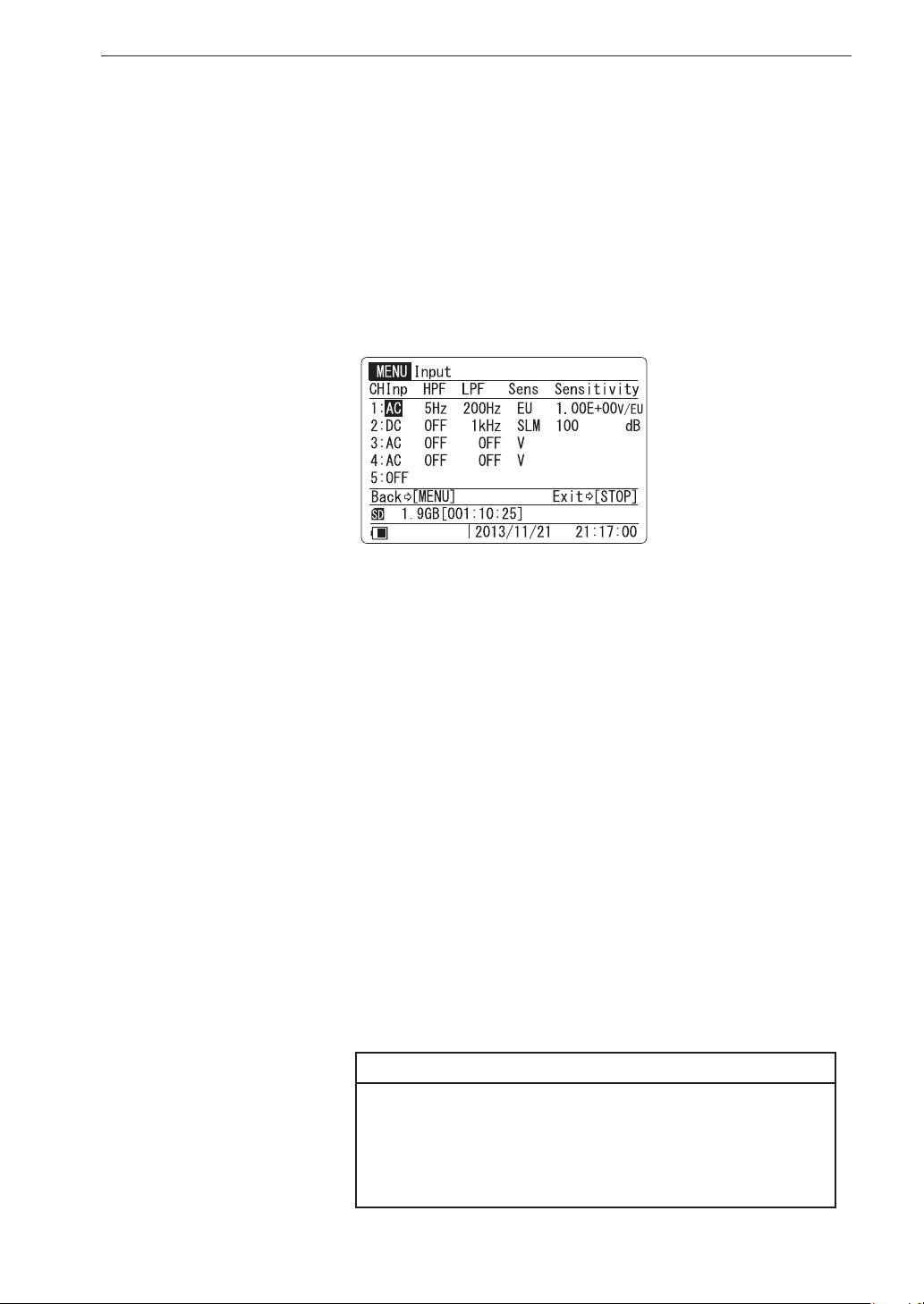
Setting items are organized in six pages, with related items appearing together
on one page. The contents of each menu page are described below.
<Input> menu
Allows you to select the sensor (signal) type, input signal ltering, sensor
sensitivity level and units for each channel.
Menu Operations and Setting Items
Inp Sensor (signal) type setting (CH1 to CH4)
Controls the input on/off setting and sensor (signal) type.
OFF Select this setting when the input is not to be used.
DC This setting is for input of an electrical signal, with the re-
cording to include DC components. This is suitable for en-
vironment sensors (temperature, wind speed, pressure, etc.)
and sound level meters that output the measurement value as
a DC signal. The setting should also be used when recording
a signal (such as from a vibration level meter) that comprises
frequency components below 1 Hz.
AC This setting is for input of a normal electrical signal, with
the recording to exclude DC components. This is suitable for
sound level meters, vibration meters and similar equipment
that outputs the measurement value as an AC signal. The cutoff
frequency is about 0.3 Hz.
Note
When Input is set to AC, a high-pass lter with a cutoff
frequency of 0.3 Hz is applied. However, if the input
signal contains h igh-level DC components t hat exceed
the input range, overload may occur in the DA-21.
39
Page 52

Menu Operations and Setting Items
CCLD This setting is for microphones, accelerometers and other
sensors that require a sensor drive power supply. (See the
section starting on page 63.)
(CCLD: Constant Current Line Drive)
Note
If the unit is operated on battery power, take the
following points into account when setting the Inp
to CCLD.
When quitting the menu, if battery capacity is too
low for supporting CCLD operation, the unit will
switch itself off automatically.
In such a case, replace all batteries with fresh ones,
or connect an AC adapter or other external power
supply.
VP4x Select this setting when the accelerometer is connected to the
unit via the charge converter VP-40 etc. (see page 63).
Inp Tachometer signal, voice memo, marker setting (CH5)
This setting determines which signal type information is shown in the
CH5 area during recording.
OFF Select this setting if no signal assigned to CH5 is input.
Tacho Select this setting if a rotary pulse signal (tacho signal) is
supplied to the rotary pulse input connector.
Voice Mem o
Select this setting if the optional voice memo microphone is
connected to the Voice Input connector and used for recording
voice memos.
Marker Select this setting if the switch of the connected voice memo
microphone is used for the marker function.
Voice memo recording is possible at the main screen, except when the
setting is “OFF”.
40
Page 53
Menu Operations and Setting Items
HPF High-pass lter frequency setting
Enables a high-pass lter for the input signal. The HPF frequency indi-
cates the cutoff frequency.
Available settings are OFF and 5 Hz.
When the Inp setting is DC, only the OFF setting is available for the
high-pass lter.
OFF / 5 Hz
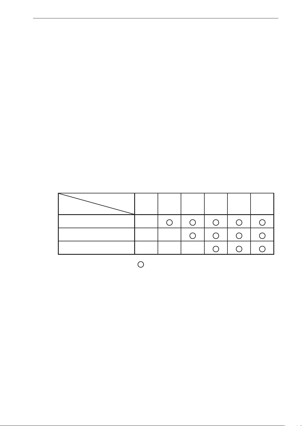
LPF Low-pass lter frequency setting
Enables a low-pass lter for the input signal. The LPF frequency indicates
the cutoff frequency.
Available settings are OFF, 200 Hz, 1 kHz, and 2 kHz, but only selections
that are within the frequency range setting are allowed.
OFF / 200 Hz / 1 kHz / 2 kHz
Available parameter list
Frequency range
LPF
200 Hz
1 kHz
2 kHz
100 Hz 500 Hz 1 kHz 5 kHz 10 kHz 20 kHz
×
××
×××
• • • Available × • • • Not available
41
Page 54
Menu Operations and Setting Items
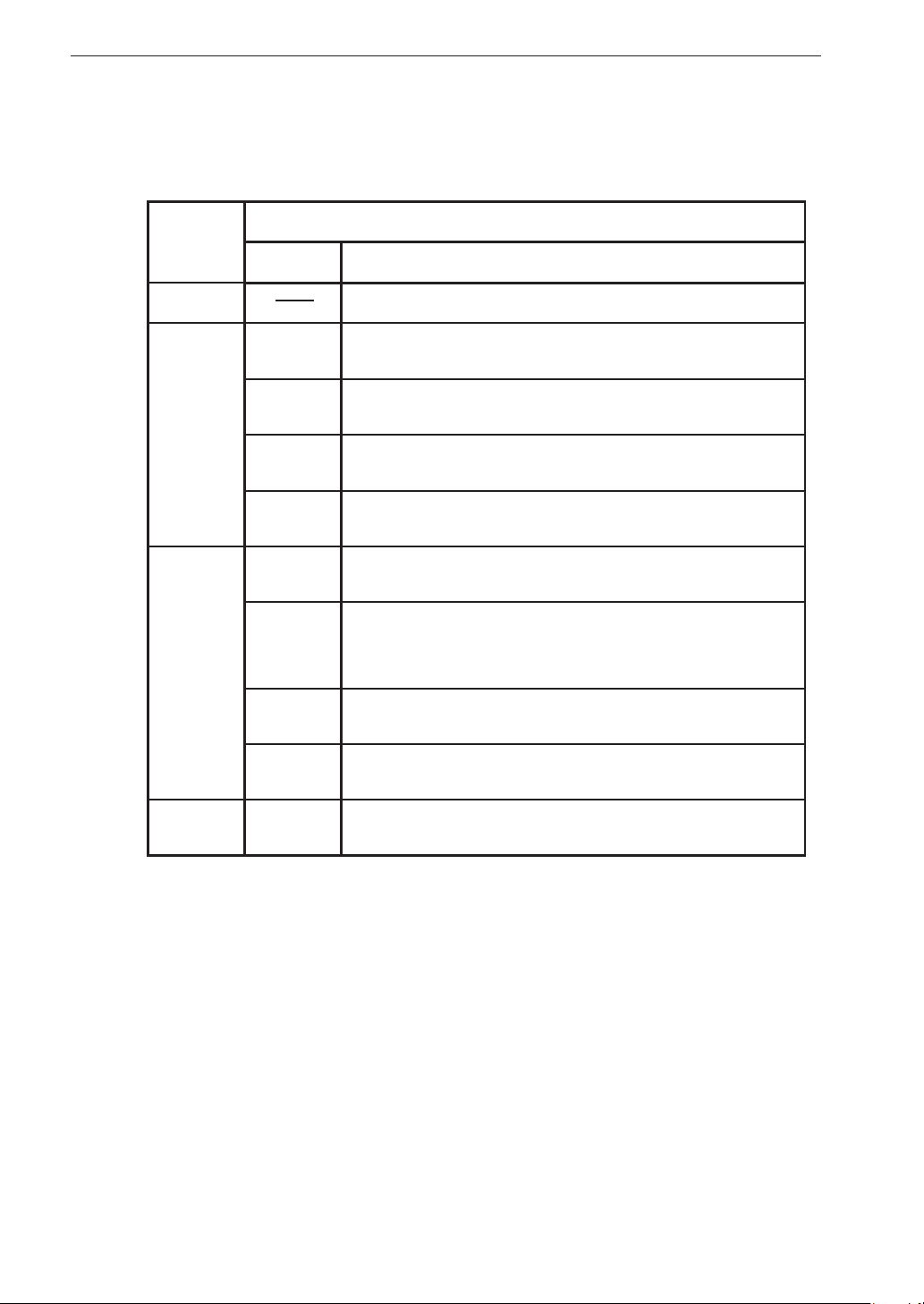
Sens Sensor type setting
Lets you select the sensor type and make other sensor related settings.
Available options depend on the Inp setting.
Inp
setting
Available Sensor settings (depending on Inp) and description
Sens Description
OFF No setting available
V
EU
Record input voltage from sensor or measuring
instrument as is.
Convert input voltage from sensor or measuring
instrument into EU for recording.
AC/DC
SLM
VM
V
Sound level meter (with AC or DC output) is connected.
Vibration level meter (with AC or DC output) is
connected.
Constant Current Line Drive compatible sensor is
connected. Record input voltage from sensor as is.
Constant Current Line Drive compatible sensor is
EU
CCLD
MIC
connected. Convert input voltage from sensor into
EU for recording.
Constant Current Line Drive compatible microphone
is connected.
42
PICK Accelerometer with built-in preampli er is connected.
VP4x PICK
Accelerometer via charge converter VP-40 etc. is
connected.
EU (Engineering Units) is a unit symbol for expressing various physical
quantities detected by a sensor.
Page 55
Menu Operations and Setting Items
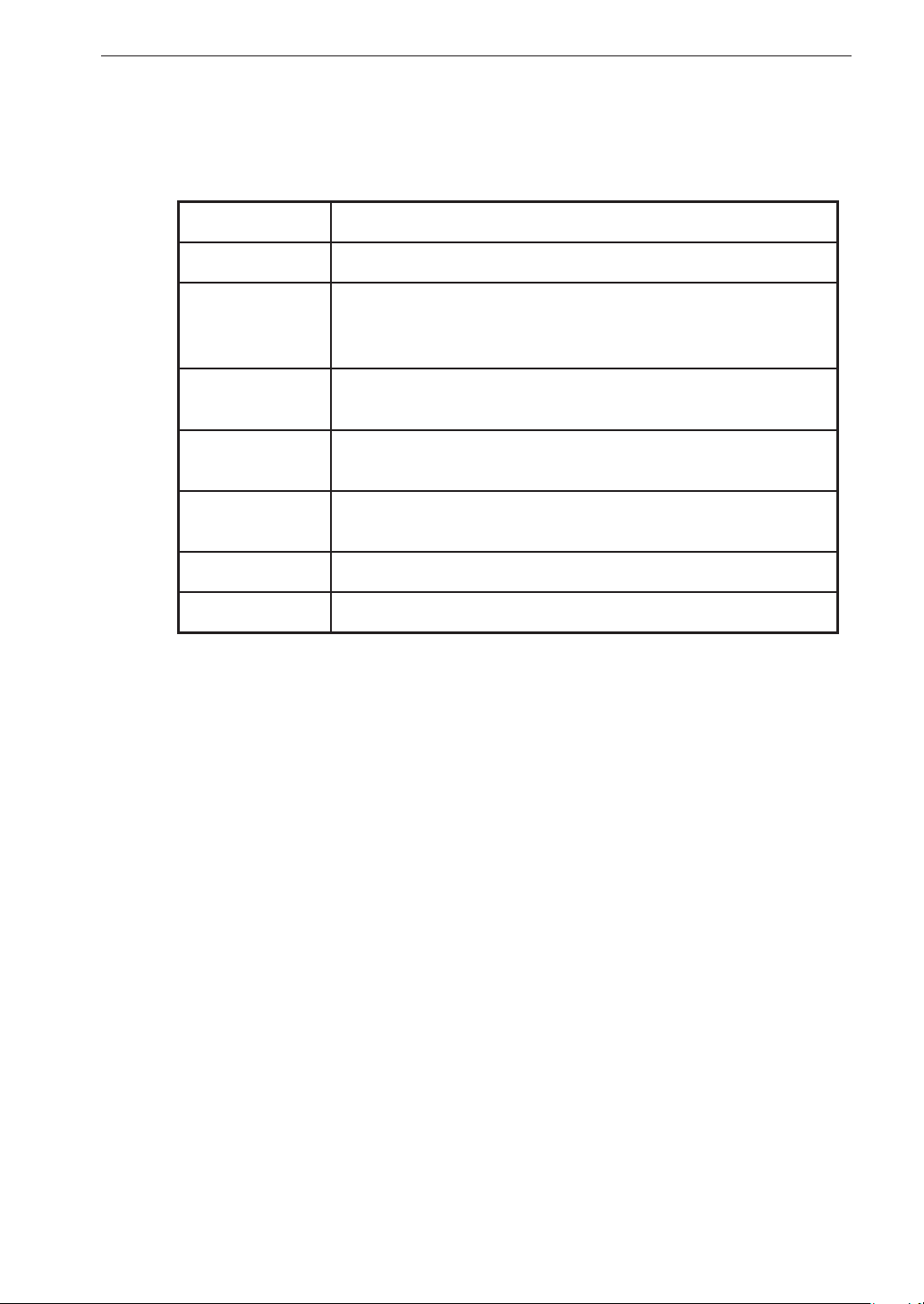
Sensitivity Unit conversion value setting
Speci es the relationship between input signal voltage and measurement
value, according to the preceding Sensor type setting (Sens).
Sens setting Sensitivity setting (depending on Sens)
VNo setting
Voltage per EU (V/EU)
EU
(Note that the EU setting value is the inverse of that used
in the DA-20.)
MIC
PICK (CCLD)
PICK (VP4x) Charge sensitivity of accelerometer [pC/(m/s
Constant Current Line Drive compatible microphone
sensitivity level (dB)
Voltage sensitivity of accelerometer with built-in pream-
2
pli er [mV/(m/s
)]
2
)]
SLM Sound level meter level range (dB)
VM Vibration level meter level range (dB)
For additional information on the Inp, Sens, and Sensitivity settings, see also
pages 65 to 69.
43
Page 56
Menu Operations and Setting Items
<Rec.Parameters> menu
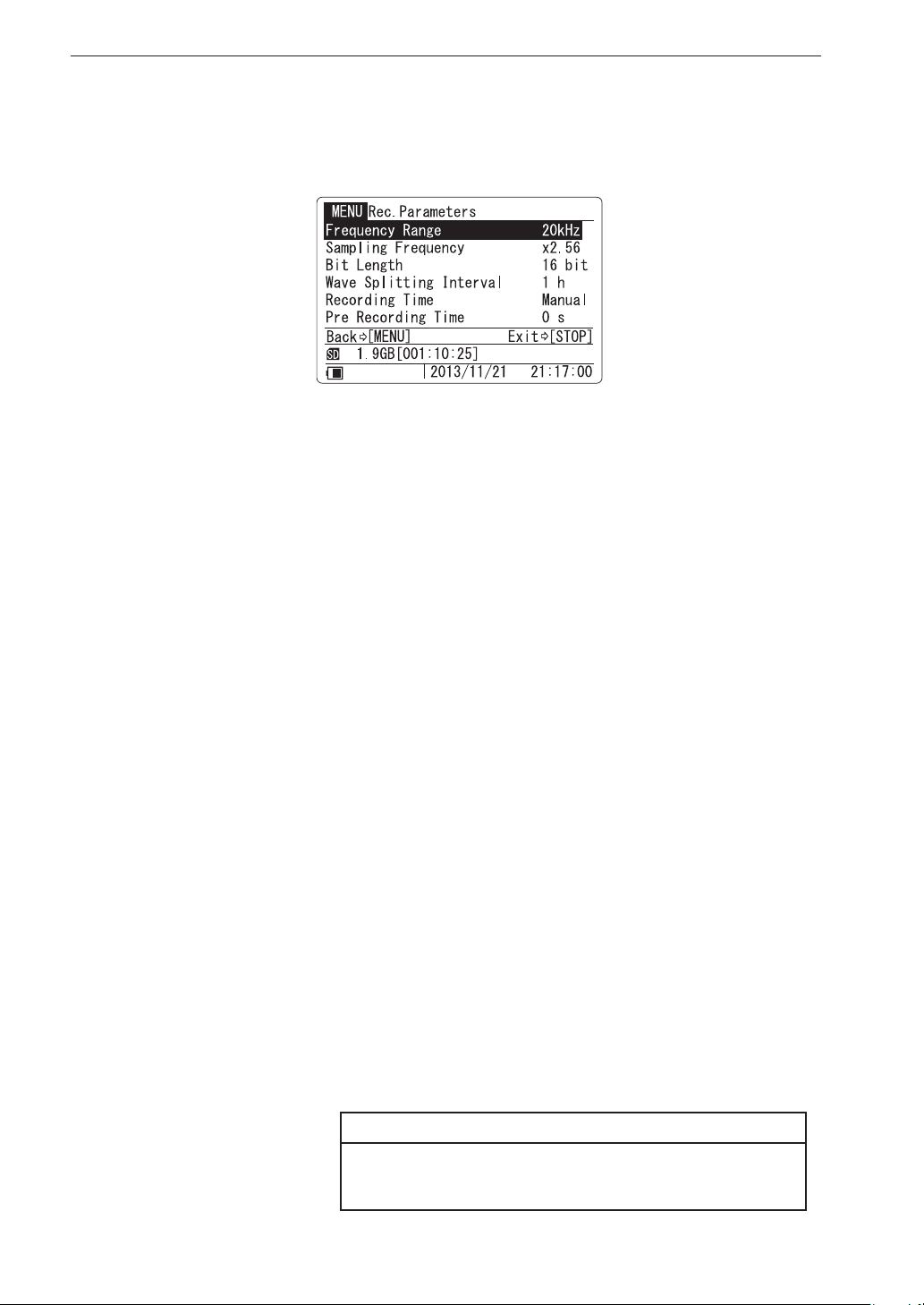
This menu comprises settings for recording and auxiliary functions.
Frequency Range Frequency range setting
The value selected as the frequency range setting represents the highest
effective frequency that can be included in the recorded data.
Available settings are 100 Hz, 500 Hz, 1 kHz, 5 kHz, 10 kHz, and 20 kHz.
100 Hz / 500 Hz / 1 kHz / 5 kHz / 10 kHz / 20 kHz
Sampling Frequency Sampling frequency setting
The DA-21 provides a choice of two sampling frequency settings com-
monly used for frequency analyzers and voice processing: 2.4 times or
2.56 times the frequency range. FFT analyzers generally use 2.56 times.
×2.4 / ×2.56
Bit Length Bit length setting
Select the recording data bit length. Increased accuracy of analysis and
better sound quality can be obtained as the value increased.
Available settings are 16 bit and 24 bit.
16 bit / 24 bit
Wave Splitting Interval Set splitting interval for recording data
The setting determines the size of a single le when recording data in
channels 1 to 4. Available settings are 10 minutes and 1 hour.
10 min / 1 h
Note
44
Rotary speed data and voice memo data recorded in
channel 5 are not split.
Page 57
Menu Operations and Setting Items
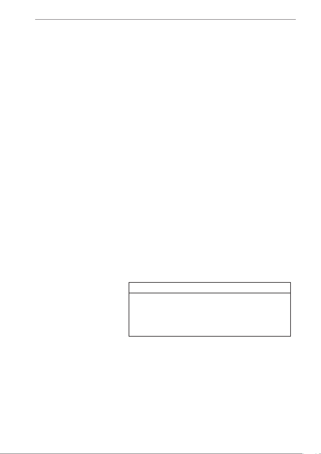
Recording Time Recording time setting
The recording time can be set in hours, minutes, or seconds, and a Manual
setting is also available. When Manual is selected, the recording time
is not preset, allowing the operator to press the [STOP] key whenever
required. With the Manual setting, recording will automatically stop
after 1000 hours have elapsed. A recording time that is longer than that
available with the inserted SD memory card cannot be set.
The sub menu moves in the following order for the recording time (1 to
59 / 1 to 24 / Manual) and the unit (s, m, h).
When data for the preset recording time have been collected, recording
stops automatically. However, if the [STOP] key is pressed before that,
or if the SD memory card becomes full, recording stops at that point.
1 s to 59 s (seconds) / 1 m to 59 m (minutes) / 1 h to 24 h (hours) / Manual
Pre Recording Time Pre-recording time setting
When recording is started by pressing the [REC] key or by a trigger event,
the pre-recording function allows data from a range before the actual start
point to be included in the recording. The Pre Recording Time value de-
termines the duration of the range for such data. Available settings are 0
s, 1 s, and 5 s (seconds). To disable the function, select the “0 s” setting.
For more information, refer also to page 76.
0 s / 1 s / 5 s
Note
After changing the frequency range or channel
setting, the [REC] key will be inactive for the Pre
Recording Time interval, and recording cannot be
started during this interval.
45
Page 58
Menu Operations and Setting Items
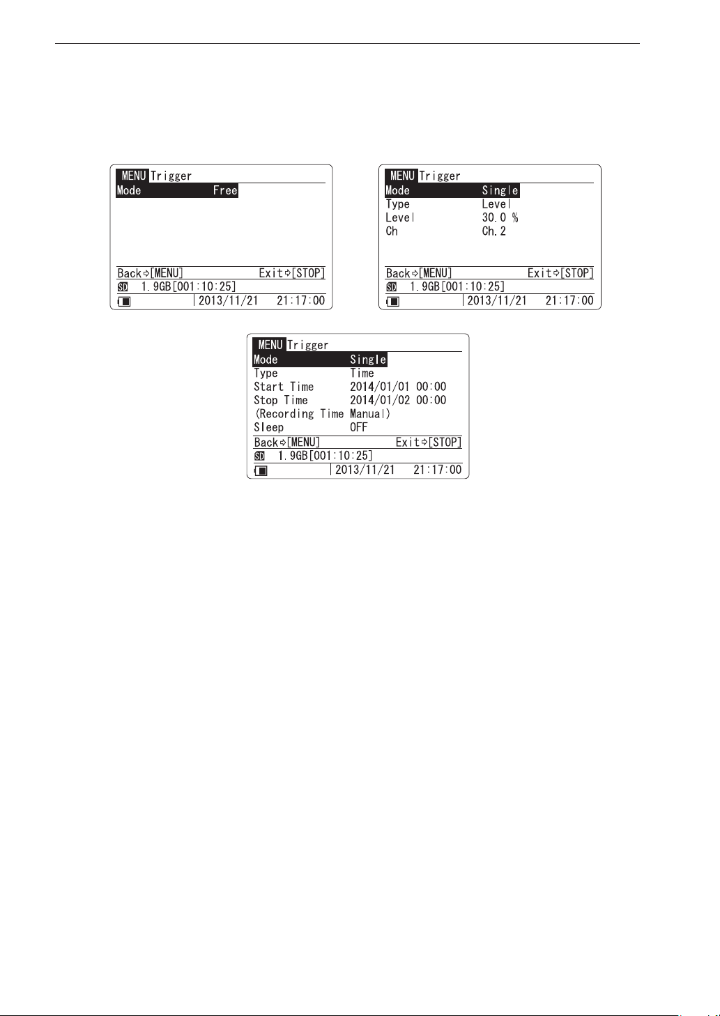
<Trigger > menu
Comprises trigger related items (see pages 77 to 83).
Mode Trigger operation mode setting
Determines the basic operation when a trigger event occurs. If trigger
operation is not required, choose the “Free” setting.
Free Trigger is not active. Recording starts immediately when the
[REC] key is pressed.
Single The unit goes into trigger standby mode when the [REC] key
is pressed. When a trigger event occurs, recording starts. When
the amount of data corresponding to the recording time has
been recorded, recording stops.
Repeat The unit goes into trigger standby mode when the [REC] key
is pressed. When a trigger event occurs, recording starts. When
the amount of data corresponding to the recording time has
been recorded, the unit again goes into trigger standby mode.
This is repeated with every trigger event until the [STOP] key
is pressed or the SD memory card becomes full.
Master If you synchronize two DA-21 units, the unit used as slave is
selected this mode automatically.
46
Page 59

Menu Operations and Setting Items
Type Trigger signal type setting
Determines the type of trigger signal. When the “Mode” item is set to
“Free”, this item does not appear.
Level A trigger event occurs and recording is started when the level
of the input signal in the speci ed channel (trigger channel)
becomes a preset value (trigger level) or higher.
External
A trigger event occurs and recording is started when the Ext.
Trig. connector is shorted.
External Gate
Recording is carried out only while the Ext. Trig. connector is
shorted (gate trigger operation). When the Ext. Trig. connec-
tor goes open, recording will stop after a delay of 5 seconds
(post-recording).
Time Recording is carried out from the speci ed Start Time to the
speci ed Stop Time, at intervals as speci ed by the Interval
setting.
Level Trigger level setting
When the trigger signal type is “Level”, a trigger event occurs when the
absolute value of the input signal waveform exceeds the trigger level. The
trigger level is a threshold set as a relative percentage [%] correlated to
the full-scale value of the input range setting that is active at the time of
recording.
Consequently, the actual trigger level (input signal waveform value) will
change when the input range setting is changed.
The trigger level is indicated on the bar graph for the trigger channel (see
page 26).
Ch Trigger channel setting
When the trigger signal type is “Level”, a channel (1 to 4) must be spec-
i ed for monitoring. This is called the trigger channel.
47
Page 60
Menu Operations and Setting Items
Start Time/Stop Time Recording start time/stop time setting
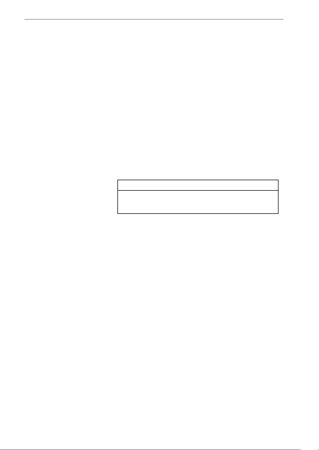
Lets you specify a start time and stop time for recording. These settings
can span two different calendar years.
When the start time setting is before the current time, the setting auto-
matically becomes “current time + 5 minutes”. When the stop time setting
is before the current time, the setting automatically becomes “Start Time
+ 24 hours”.
Interval Recording interval setting
When the trigger signal type has been set to “Time” and the trigger mode
to “Repeat”, the recording interval can be set here. The following settings
are available.
5 m / 10 m / 15 m / 30 m / 1 h / 8 h / 24 h
Note
The interval setting must be longer than the “Recording Time” as set in <Rec.Parameters> menu.
48
Page 61
Menu Operations and Setting Items
Sleep Sleep function setting
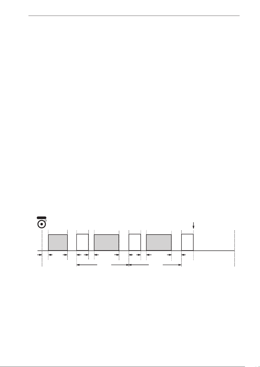
When the trigger signal type is set to “Time”, this setting controls the use
of sleep mode during recording.
OFF/ON
When sleep mode is ON, the unit goes into the power save state about 60
seconds after standby was activated by pressing the [REC] key. When
Mode is set to “Repeat”, the unit will enter the power save state also
between recording intervals.
In the power save state, the LCD screen is off.
About 90 seconds before recording start, the unit wakes up and goes into
standby until the actual start.
Pressing the LIGHT key in the power save state temporarily turns on
the LCD screen. If no further key is pressed, the unit will return to the
power save state.
Recording start
REC
Sleep
(low power
consumption)
60
sec.
Operation example for sleep mode
DA-21 settings
Mode: Repeat
Start Time: 2014/01/15 12:00
Stop Time : 2014/01/15 15:00
Interval: 1h (1 hour)
Recording Time: 10m (10 minutes)
12:00 13:00 14:00 15:00
90
sec.
Data
recording
10 min.
Sleep
(low power
consumption)
60
sec.
1 hour 1 hour
90
sec.
Data
recording
10 min.
sec.
60
Sleep
(low power
consumption)
90
sec.
After completion of recording,
the unit does not go into
the power save state.
Data
recording
10 min.
49
Page 62
Menu Operations and Setting Items
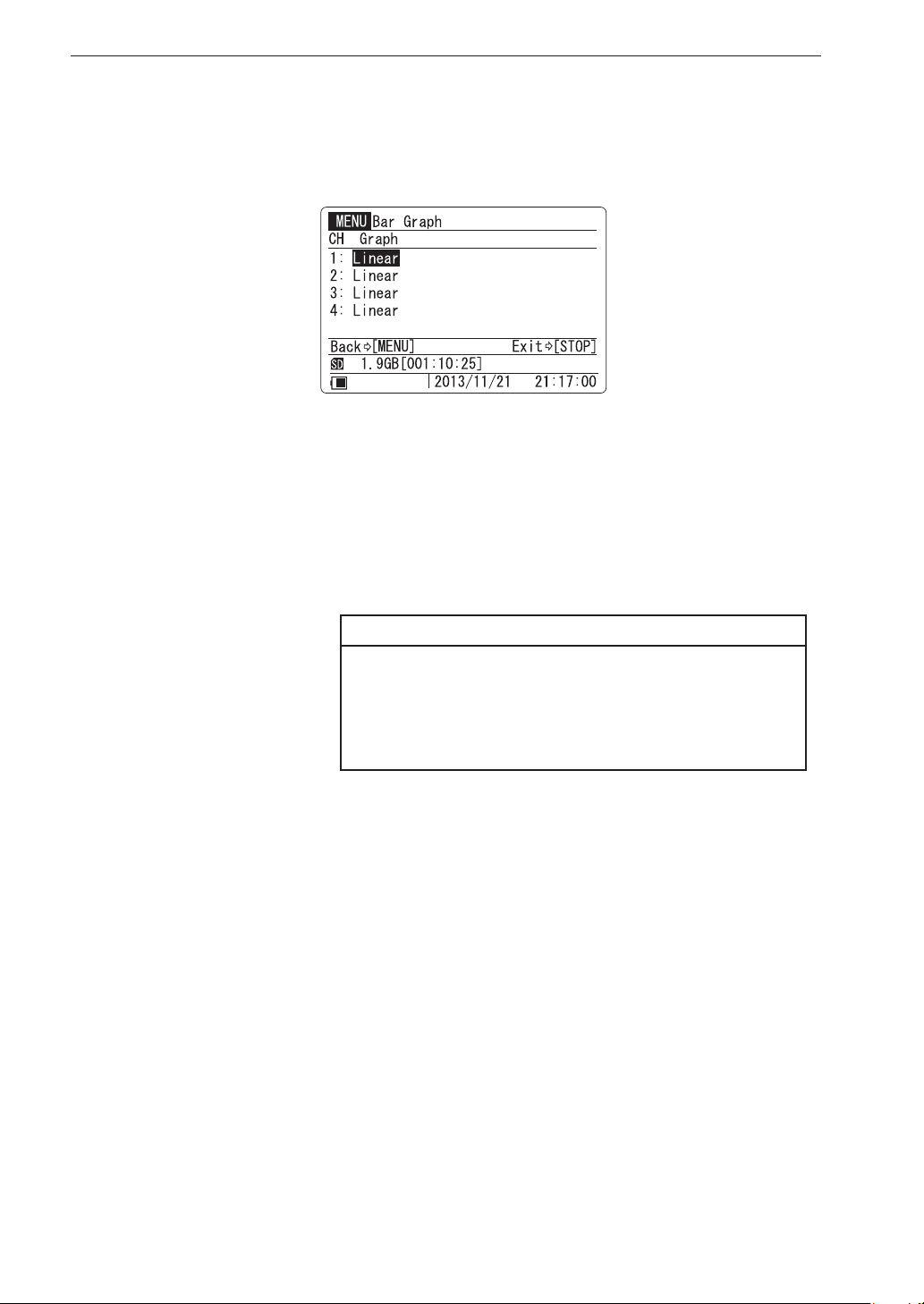
<Bar Graph> menu
This menu serves for making bar graph display settings.
Graph Bar graph display method
Lets you select linear value display (Linear) or logarithmic value display
(Log) for each channel.
For details on the bar graph display method, see page 27.
Linear / Log
Note
The Graph menu will be blank for channels whose
“Sensitivity” has been set to MIC, SLM, or VM with
<Input> menu. The bar graph indication for such
channels is xed to dB.
50
Page 63
Menu Operations and Setting Items
<System> menu
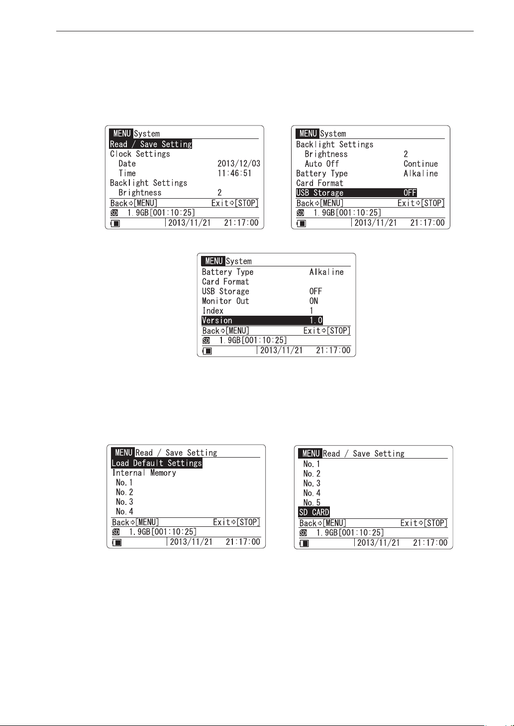
This menu comprises general items such as display backlight brightness and
SD memory card data deleting.
Read / Save Setting Read setting values from unit or SD
memory card/Save setting values in unit
or on SD memory card
Load Default Settings
Returns all unit settings to the initial (factory default) condition. In the
<Read / Save Setting> menu, select “Load Default Settings” and press
the [ENT] key. The execution choice screen appears.
51
Page 64
Menu Operations and Setting Items
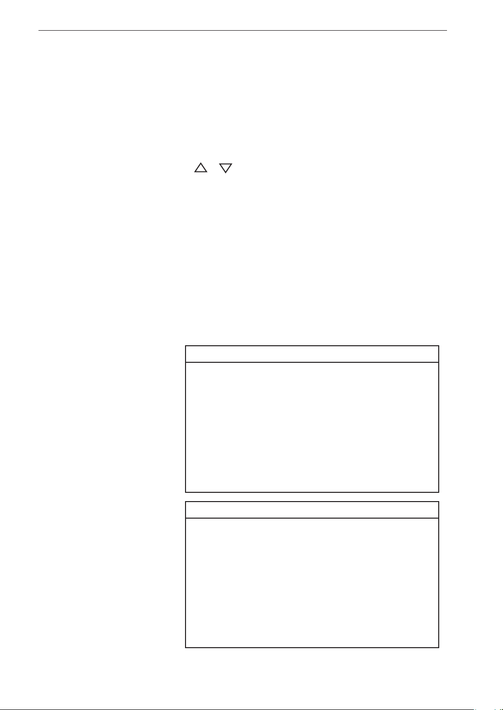
Internal Memory (No. 1 to No. 5)
Input range and other settings made with the menus can be saved in the
internal memory of the unit, allowing them to be easily read (reloaded)
later. Five sets of settings identi ed as No. 1 to No. 5 can be saved. In
the <Read / Save Setting> menu, select No. 1 to No. 5 for “Internal
Memory” and press the [ENT] key. A screen to save or read settings
appears. Use the [
]/[ ] keys to select the desired action and press
the [ENT] key. The execution choice screen appears.
SD CARD
The input range and other settings made with the menus can be saved on
an SD memory card for later use. Only one set of settings can be saved.
The steps for saving and reading are the same as for “Internal Memory”
described above. The setting le saved on the SD memory ca rd can also
be used as st a rt up le for loading when the unit is turned on (see page 14).
If the message “Card Error.” appears when you press the [ENT] key to
update the setting le, the SD memory card may be defective.
Important
Changes to settings made with the menus will
be saved on the SD memory card by the “Save
Settings” function, but for the unit, the settings
will only be activated at the point where you
return to the main screen.
If you turn the power off before returning to the
main screen, the changed settings will not be
active the next time you turn the unit on.
52
Note
When a setting le is loaded which contains a CCLD
setting for the Inp item of <Input> menu, the channels
for which CCLD is selected will be supplied with a
constant current.
If the unit is operated on battery power and the
remaining capacity of the batteries is low, a forced
power-down will occur when a CCLD setting is
selected (see page 40).
Page 65

Menu Operations and Setting Items
Clock Settings Current date and time setting
Date
Select “Date” and press the [ENT] key. Set the year (to 2037), month,
and day separately on the displayed sub menu.
Time
Select “Time” and press the [ENT] key. Set the hours, minutes, and
seconds separately on the displayed sub menu.
Backlight Settings Backlight brightness and auto off time
setting
Brightness
Select the grade of backlight brightness from the number of 1 to 4.
Auto-Off
When no key is operated for the period set here, the backlight will be
automatically turned off. Available settings are 30 s (seconds), 3 m
(minutes), and Continue. To have the backlight continuously on, select
Continue.
Battery Type Used battery type setting
Displays the sub menu to select the type of battery used for the unit. The
remaining battery capacity corresponding to the selected battery is dis-
played on the main screen. Available settings are Alkaline and Ni-MH
(nickel-metal hyd r ide).
Alkaline / Ni-MH
Card Format SD card formatting
Formats the inserted SD memory card.
Select “Card Format” and press the [ENT] key. The execution choice
screen appears.
USB Storage Function setting for connection to computer
When set to “ON”, connecting the unit to a computer via USB will cause
the SD memory card inserted in the unit to be recognized as a removable
disk. Data recording and data recall operation cannot be performed when
the state of “USB Storage” is set to “ON”.
53
Page 66

Menu Operations and Setting Items
Monitor Out Function setting for Monitor Out connector
When set to “ON”, a playback signal for the monitor channel is output
from the Monitor Out connector.
For details about playback, refer to the section beginning on page 111.
Index Device index number setting
Using this setting, you can assign a unique number to each DA-21 device.
The setting range is 1 to 255. Because the index number information is
recorded along with the data, it can be used to identify multiple DA-21
units or data recording conditions.
The index number setting has no in uence on performance or functions
of the unit.
Version Version information
Displays the rmware version of the unit.
54
Page 67
Menu Operations and Setting Items
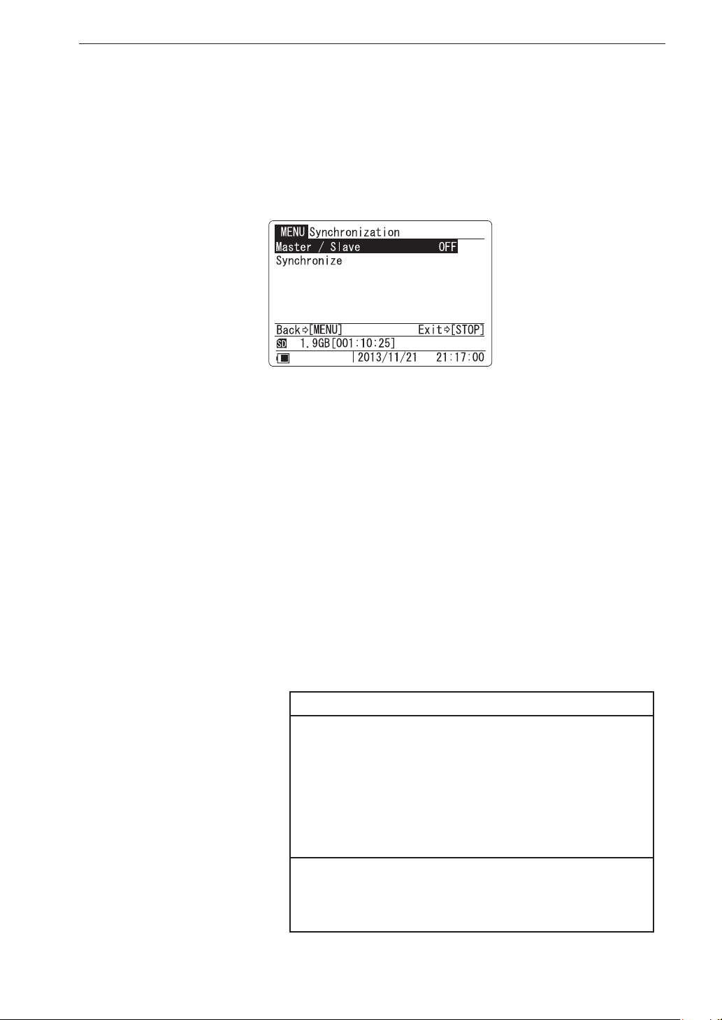
<Synchronization> menu
Contains settings for operating two connected DA-21 units as a synchronized
system.
For additional information on DA-21 synchronized operation, also refer to
page 91.
Master / Slave Assign unit to master or slave operation
After connecting two DA-21 units, this setting determines whether the
respective DA-21 unit operates as master or as slave.
OFF No synchronized operation.
Master Select this setting on the DA-21 to be used as master.
Slave Select this setting on the DA-21 to be used as slave.
Synchronize Synchronize connected DA-21 units
Use the dedicated cable to connect the two DA-21 units to be used as
master and slave. Select this item on both units and press the [ENT] key.
The execution choice screen appears. Then press the [ENT] key on both
unit simultaneously. Two connected DA-21 units synchronize.
Important
Establish the same settings on both DA-21 units
(<Rec.Parameters> menu items). If settings are
different, synchronized operation is not possible.
Also, when the settings are changed after the
synchronization, it is necessary to synchronize
again.
Check the synchronization information on the
display (page 18) after operation of the synchronization.
55
Page 68

Preparations
This chapter describes the settings and steps to take before starting to record
data.
Preparations and checks before recording
1. Power supply (inserting batteries, AC adapter, wake-up-on-power mode)
2. SD memory card preparations (insertion and removal, formatting)
3. Connection of external devices (sensors etc.)
4. Sensitivity setting
Recording parameter settings
1. Input range, overload
2. Frequency range, sampling frequency
3. Recording time, trigger
Auxiliary function setup
1. Device index number
2. Voice memo/marker
3. Preventing inadvertent operation
4. Remote control operation
5. Connection to a computer
6. Inter-unit synchronization
7. Tachometer signal input
56
Page 69
Preparations
Preparations and checks before recording
Power supply
The DA-21 can be powered from four IEC LR6 (size AA) batteries or from
the optional AC adapter NC-98C.
Important
Use only the speci ed AC adapter available as an option for the DA-21.
Inserting the batteries
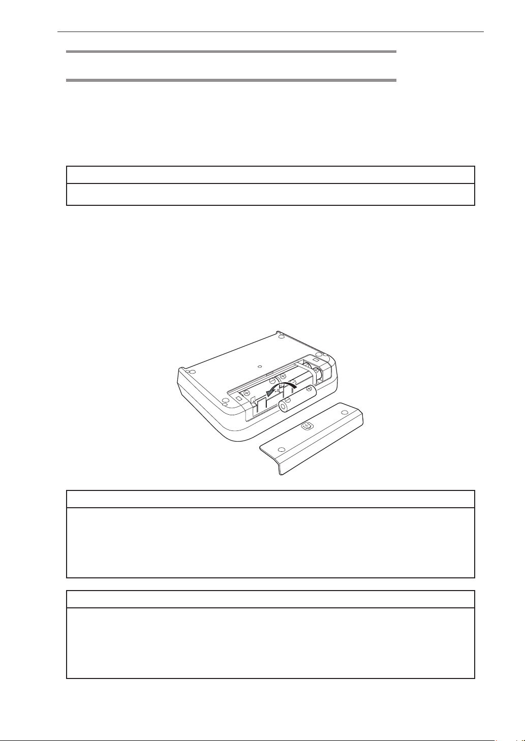
1. Open the battery compartment cover.
2. Insert four IEC LR6 (size AA) batteries with correct polarity, as
shown inside the compartment.
3. Replace the battery compartment cover.
Important
Take care not to reverse the (+) and (-) polarity when inserting the batteries.
Always replace all four batteries together. Do not mix old and new batteries
or batteries of different type. Remove the batteries from the unit if the unit
is not to be used for an extended period.
Note
If the unit is operated on battery power, take the following points into account
when using a CCLD type sensor. When quitting the menu after setting the “Inp”
item of <Input> menu to CCLD, the unit may switch itself off automatically. In such
a case, replace all batteries with fresh ones.
57
Page 70
Preparations
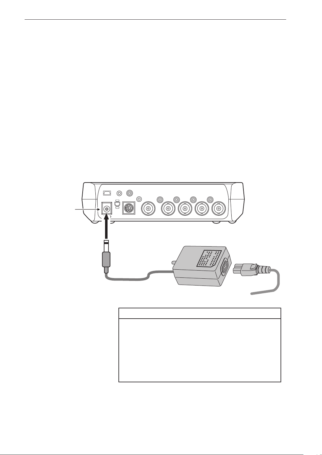
Connecting the power cord and AC adapter (option)
Connect the AC adapter as shown below. Turn the unit off before making
this connection.
1. Plug one end of the power cord into the small socket on the AC
adapter.
2. Insert the plug of the supply cable from the AC adapter into the
DC IN connector on the DA-21.
3. Plug the other end of the power cord into an AC outlet.
To remove the AC adapter, turn the DA-21 off and then perform the above
steps in reverse order.
Voice
Ext. Trig.
Input
DC IN connector
USB
DC IN 5-20V
Sync.
Remote Controller
Monitor
Out
Tacho
Output
4
2
3
1
Input
AC adapter
NC-98C (option)
To AC outlet, 100 V to 240 V, 50 Hz / 60 Hz
Important
Use only the speci ed AC adapter available as
an option for the DA-21. Using another kind of
AC adapter may lead to damage and malfunction. When connecting a battery or purpose-built
cable to the DC-IN connector, take great care
to ensure correct polarity and voltage.
58
Page 71
Preparations
Backup battery
The unit uses a backup battery (rechargeable battery) to operate the clock.
While power to the unit is on, the backup battery will be charged. It will
also be charged while power to the unit is off if external power is connected.
The relationship between charging time and retention period is shown below.
A full charge of the backup battery is achieved after 24 hours.
Charging time Retention period
1 hour 2 days
12 hours 30 days
24 hours 45 days
Use the AC adapter when connecting external power for battery charge while
the unit is turned off. The service life of the backup battery is limited. You
should have the battery replaced about once every ve years. Please contact
your supplier.
Note
The charging time, retention period and service life
of the backup battery may vary depending on the
operating condition.
When the backup battery is old, the retention period will be shorter.
59
Page 72
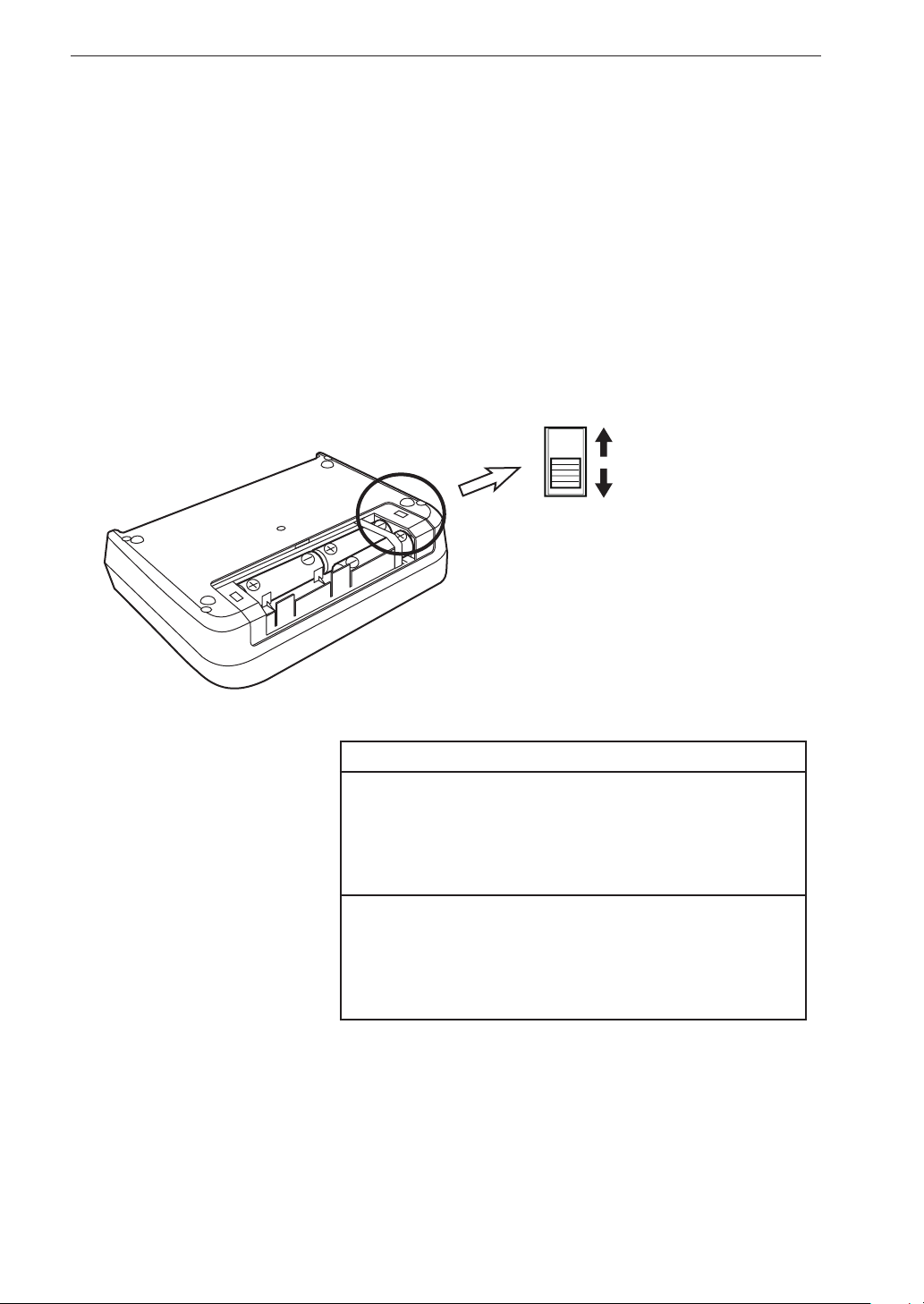
Preparations
Wake-up-on-power mode
When you open the battery compartment cover as shown below, the [WAKE
UP ON POWER] switch becomes accessible. By setting this switch to ON,
you can have the on/off status of the unit controlled by the power supplied
to the DC-IN connector. In such a case, the [POWER] key on the panel has
no effect.
WAKE UP
ON POWER
ON
Power is controlled by
external power supply
OFF
Power is controlled by
[POWER] key
Important
When setting the [WAKE UP ON POWER] switch
to ON, remove all batteries from the battery
compartment. Otherwise the wake-up-on-power
mode will not operate normally.
Remove the batteries from the unit if it is to be
stored for a long time with the [POWER] key set
to OFF to prevent possible damage caused by
battery leakage.
60
Page 73
SD memory card preparations
Recorde d data are saved on SD memory cards in WAVE le format. To enable
storing of recorded data les on an SD memory card, a special data manage-
ment le and directory structure particular to the DA-21 is required on the
card. When you insert a blank SD memory card and format it by the DA-21,
this directory structure and data management le are automatically created.
An SD memory card inserted in the unit will be recognized as a removable
disk by the computer when the “USB Storage” item of <System> menu is set
to “ON”, without having to install a USB driver.
For connection to the DA-21 and the computer, use an optional (generic) A
- mini B USB cable.
SD memory cards even from the same manufacturer and of the same type exhibit certain
variations in specifications which may cause
problems. For this reason, be sure to use only
the SD memory cards provided by Rion. The
performance of other cards is not guaranteed.
Preparations
Important
This unit supports SD memory cards and SDH C
memory cards, but not SDXC memory cards.
Format the SD memory card by the DA-21 before recording.
If folders or les on the SD memory card have
been altered by other equipment except the DA21, do not continue to use the card for recording
in the DA-21. Data may not be recorded correctly.
61
Page 74
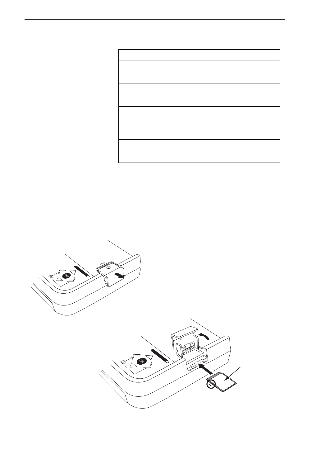
Preparations
Inserting and removing an SD memory card
Important
Make sure that power is OFF before inserting
or removing a card.
Take care to insert the SD memory card with
correct orientation.
If the SD memory card is removed while data is
being read or written to the card, the data may
be destroyed.
Note that we assume no responsibility for any
damage or loss of stored measurement data.
1. Open the card slot cover of the unit.
2. Insert the SD memory card into the card slot with the label of the
card facing up. Push the card in until it is locked in place.
3. To remove the card, push the card a bit further in, the card is released
and pops out of the card slot.
CARD CAPACITY
Slide card slot
cover out
Raise card
slot cover
CARD CAPACITY
Label side should
face up
SD memory
card
By sliding this switch in
the arrow direction, you
can write-protect the card
62
Page 75

Formatting an SD memory card
Note
When a n SD memory ca rd is format ted (i n itia l i zed),
all data present on the card will be lost. But the setting
le will remain if the card is formatted by this unit.
In the following cases, you should format the SD memory card:
• When using the SD memory card in the unit for the rst time
• When wishing to delete all data from the SD memory card
To format an SD memory card, proceed as follows.
1. Select “Card Format” on the <System> menu and press the [ENT]
key.
Preparations
2. The execution choice screen appears. Press the [ENT] key.
63
Page 76
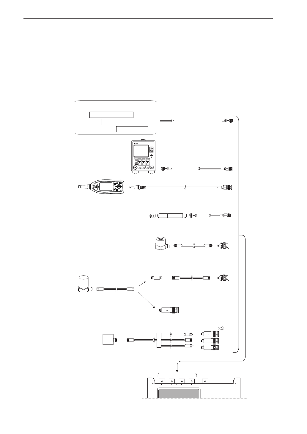
Preparations
External equipment (sensor etc.) connections
As shown below, the DA-21 is designed to handle the output of various sensors
or measuring instruments. Correct input settings must be made, depending on
the sensor and signal type and whether the sensor requires a constant current
power supply. Some possible combinations are shown below.
Measuring device with AC or DC outlet
Temperature meter
Tachometer
Other device
VM-83
VIBRATION METER
LEVEL RANGE
Vibration meter
Vibration level meter
(VM-83, VM-53 or similar)
PICKUP
HPF LPF
ACC/VEL
/DISP
HPF LPF MENU
MAXHOLD
ON/OFF
LIGHT
CAL
RHS
PICKUP
PEAK
/EQ
SENS
P-P
/EQ
POWER
COMP
HOLD
ON
ON/OFF
RESET
BNC-BNC cable
Sound level meter
(NL or NA series)
Piezoelectric accelerometer
(with built-in preamplifier)
PV-41, PV-91C etc.
Piezoelectric accelerometer
PV-85, PV-90B etc.
Accelerometer
Piezoelectric accelerometer
PV-97 etc.
Microphone
UC-59, UC-52
cable
To AC
OUT
Charge converter
VP-42
Charge converter
Tri-axial accelerometer
cable VP-51WL
BNC-mini plug cable
CC-24S
CC-24 can also be used
Preamplifier
BNC-BNC cable
NH-22
BNC adapter
VP-52C (option)
VP-51 series or cable
supplied with accelerometer
BNC adapter
VP-52C (option)
Accelerometer
cable
VP-40
VP-40 90001
RION
Charge converter
VP-40
VP-40 90001
RION
VP-40 90001
RION
VP-40 90001
RION
To input connectors
64
1
2
3
4
DA-21
Page 77

Input settings
The four signal input connectors (BNC connectors) can not only accept a
signal, they also allow output of a constant current to a CCLD (Constant Cur-
rent Line Drive) type sensor. Some CCLD sensors use a basic preampli er +
accelerometer or microphone con guration. The DA-21 can record up to four
input signals. The input connectors 1 to 4 are assigned to channels 1 to 4.
Input setting (<Input> menu: Inp)
The setting is made for each channel separately, with the “Inp” item on
<Input> menu.
AC For sensors that output an electrical signal without DC com-
ponents
DC components and components 0.3 Hz or below are blocked.
Preparations
Example: AC output of sound level meter or vibration
meter
DC For sensors that output an electrical signal including DC
Example: Temperature meter or tachometer output, DC
output of sound level meter
CCLD For sensors requiring a constant current source
For such sensors, a constant current is supplied via the input
connectors of the DA-21.
Example 1: Combination of microphone UC-52 or UC-59
or similar with preampli er NH-22 (CCLD: 2
mA) or similar
Example 2: Piezoelectric accelerometer with built-in pre-
ampli er PV-41, PV-91C, PV-97I (3-axis) or
similar
VP4x Sensor connected via the charge converter VP-40
Example: Accelerometer PV-85 or PV-90B etc. connected
via the charge converter VP-40
65
Page 78
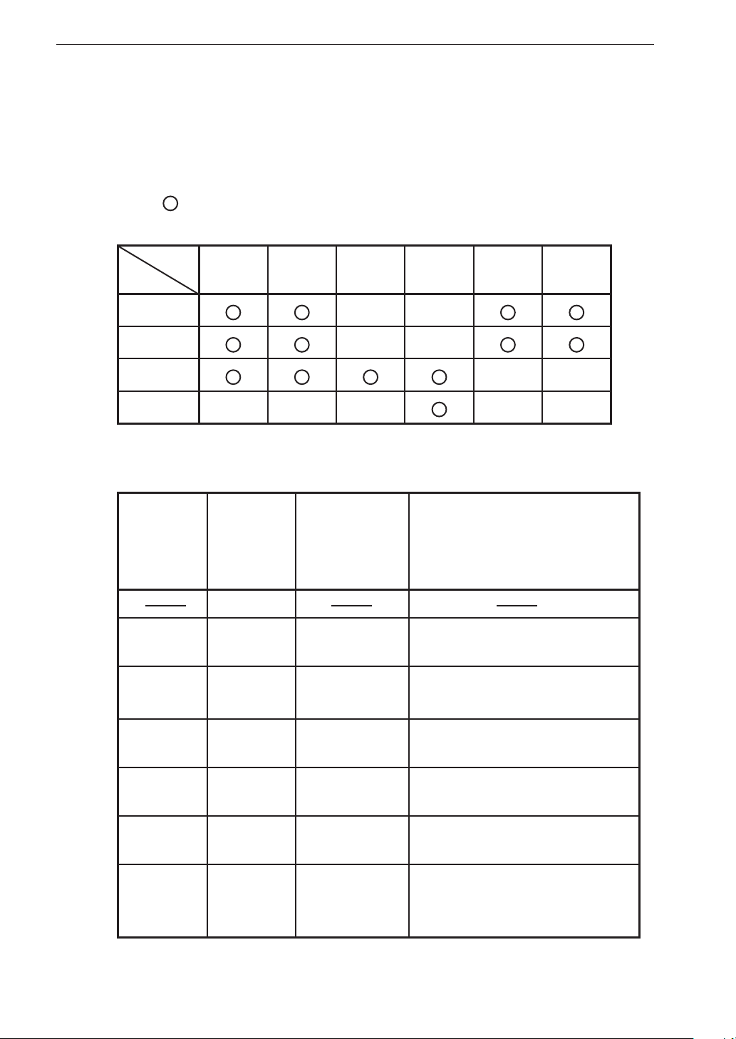
Preparations
Sensitivity setting (<Input> menu: Sens, Sensitivity)
Sensor setting
Depending on the input setting described on the preceding page (AC,
DC, CCLD, VP4x), set the “Sens” item for the combinations marked with
” in the table below. EU (Engineering Units) is a unit symbol for
a “
expressing various physical quantities detected by a sensor.
Sens
Inp
AC
DC
CCLC
VP4x
When the “Sens” item is set, the sensor signal units are determined au-
tomatically, as shown in the table below.
Indication
for Sensor
item in
menu
EU EU V/EU
VEUMICPICKSLMVM
××
××
××
××× ××
Unit as
shown on
main screen
V
Scaled unit set
for Sensitivity
item in menu
Value input for Sensitivity
Set voltage corresponding to
1 EU
66
MIC dB dB
PICK
(CCLD)
PICK
(VP4x)
SLM dB dB
VM dB dB
m/s
m/s
2
2
mV/(m /s2)
pC/(m/s2)
Set microphone sensitivity level
(dB re. 1 V/Pa)
Set sensitivity of accelerometer
(with built-in preampli er)
Set charge sensitivity of accelerometer
Set sound level meter level range
(full-scale value)
Set vibration level meter (VM-53
or similar) level range (full-scale
value)
Page 79

Preparations
Sensitivity setting
This setting determines the correlation between input signal voltage and
signal units. How the values are to be set for each signal unit is explained
below.
mV/(m/s
2
) Set the voltage sensitivity of the accelerometer.
Example: For PV-90I rated for 0.44 mV/(m/s2), the
setting should be “0.44”.
dB Set the microphone sensitivity level (dB re. 1 V/Pa), or
level range (full-scale value) of sound level meter or
vibration level meter.
Microphone
Example: For UC-53A rated for -28 dB and used
together with NH-22, the transmission
loss is taken as -0.8 dB and the setting
should therefore be “-28.8”.
Sound level meter
Set to full-scale value of level range
Example: 80 dB
Vibration level meter
Set to full-scale value of level range
Example: 80 dB
EU Set how many volts of the sensor signal voltage corre-
spond to one unit of the physical quantity.
Example: For a tachometer rated for 1 V/1000 rpm,
the setting should be “1.00E-03”.
67
Page 80
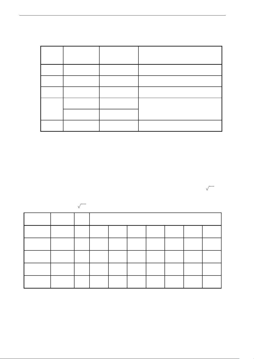
Preparations
The table below shows the correlation formula for the original input range
X [V] and the condition after the sensitivity setting.
Unit
Sensitivity
value
Inp (Sens) type Input range value after conversion
[V] None DC/AC(---) X[V]
[EU] K[V/EU] DC/AC(EU) X/K
[dB] S[dBV/Pa] MIC(CCLD) 94-S-3+20 log
2
V[mV/(m/s
2
]
[m/s
V[pC/(m/s
[dB] R[dB] SLM/VM 20 log
* Take the charge sensitivity [pC/(m/s
)] PICK(CCLD)
2
)]*PICK(VP4x)
1/(V/1000)×X
10(X )+R-10
2
)] given in the calibration certificate
10(X )
of the accelerometer and enter it as voltage sensitivity [mV/(m/s2)].
Some practical examples for applying the respective formula to actual
sensitivity values are shown below. These values are shown as input range.
(When the exponent is two digits, the mantissa is shown as one digit.
The effective number of digits for dB is three. In 3-V systems,
10
is
used instead of 3 for calculation. This is because the 3-V range actually
is 3.16 V = 10.)
Sensor Sensitivity Unit Actually displayed input range value
General 1 V 10V 3V 1V 0.3V 0.1V 0.03V 0.01V
Tach ome ter K=1.0E-03 EU 1.00 E+4 3.16E+3 1.0 0E+3 3.16E+2 1.00E+2 3.16E+1 1.0 0E+1
UC-59 S =-28.8 dB 139.8dB 129.8dB 119.8dB 109.8dB 99.8dB 89.8dB 79.8dB
PV-90I V=0.44 m/s22.27E+4 7.19E+3 2.27E+3 7.19E+2 2.27E+2 7.19E+1 2.27E+1
SLM R=80dB dB 90 80 70 60 50 40 30
68
Page 81

Preparations
Input settings and sensitivity settings for some representative sensors are
shown below for reference. The sensitivity value differs for each sensor.
Sensor example Inp Sens Sensitivity
DC output of general measuring
device or sensor, or AC output of
vibration meter
AC output of general measuring
device, sensor, vibration meter,
sound level meter
Microphone: UC-52
+
Preampli er: NH-22
Piezoelectric accelerometer
(with built-in ampli er):PV-90I
Piezoelectric accelerometer: PV-85
+
Charge converter: VP-40
Sound level meter NL series AC SLM
Vibration level meter:VM-53 AC/DC VM
DC
AC
CCLD MIC
CCLD PICK
VP4x PICK
When Inp is set to AC, a high-pass lter with a cutoff
frequency of 0.3 Hz is applied. However, if t he input
signal contains h igh-level DC components that exce ed
the input range, overload may occur in the DA-21.
Sensor sensitivity
unit
----- No setting 1
EU X.XXE+XX V/EU
----- No setting 1
EU X.XXE+XX V/EU
Sensitivity level
(-0.1 to -99.9)
Voltage sensitivity
(0.01 to 99.9)
Charge sensitivity
(0.01 to 99.9)
Voltage sensitivity
(40 to 140)
Voltage sensitivity
(40 to 140)
dB
(0 dB=1 V/Pa)
mV/(m /s2)
pC/(m/s2)
dB
dB
Note
69
Page 82
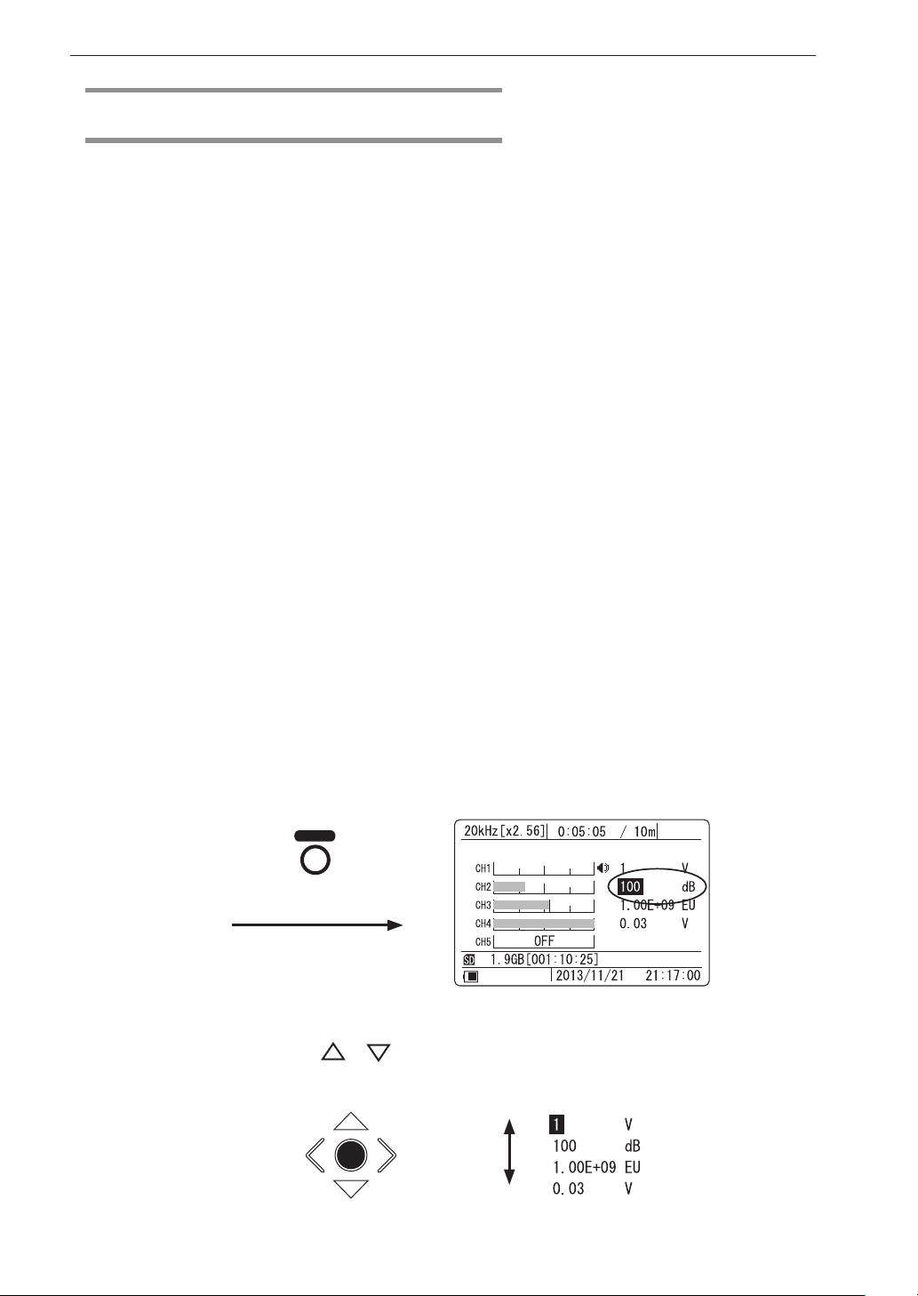
Preparations
Recording parameter settings
This section describes how to set the parameters for recording data. Input
range, frequency range, sampling frequency, and recording time are required
items. If necessary, you should also set the Pre Recording Time, trigger, and
other related items.
Input range setting
The input range can be set to seven levels in 10 dB steps (0.01, 0.03, 0.1, 0.3,
1, 3, 10 V). Select an appropriate setting according to the input signal level
and the operation method of the DA-21.
For improved S/N ratio, setting the input range as low as possible without
causing overload is generally preferred. For inspection of products and oth-
er kinds of periodic measurements, it may be necessary to keep the input
range setting the same, in order to allow product comparisons and to detect
deterioration over time.
To set the input range, proceed as follows from the main screen.
(The setting cannot be changed in recording or recall mode.)
1. Activate cursor in input range display section
Press the [RANGE] key to cause the input range display section
to be shown in reverse (cursor active).
RANGE
2. Select the channel for which to change the input range
Use the [ ]/[ ] keys to move the cursor to the channel whose
70
input range setting you want to change.
ENT
Page 83
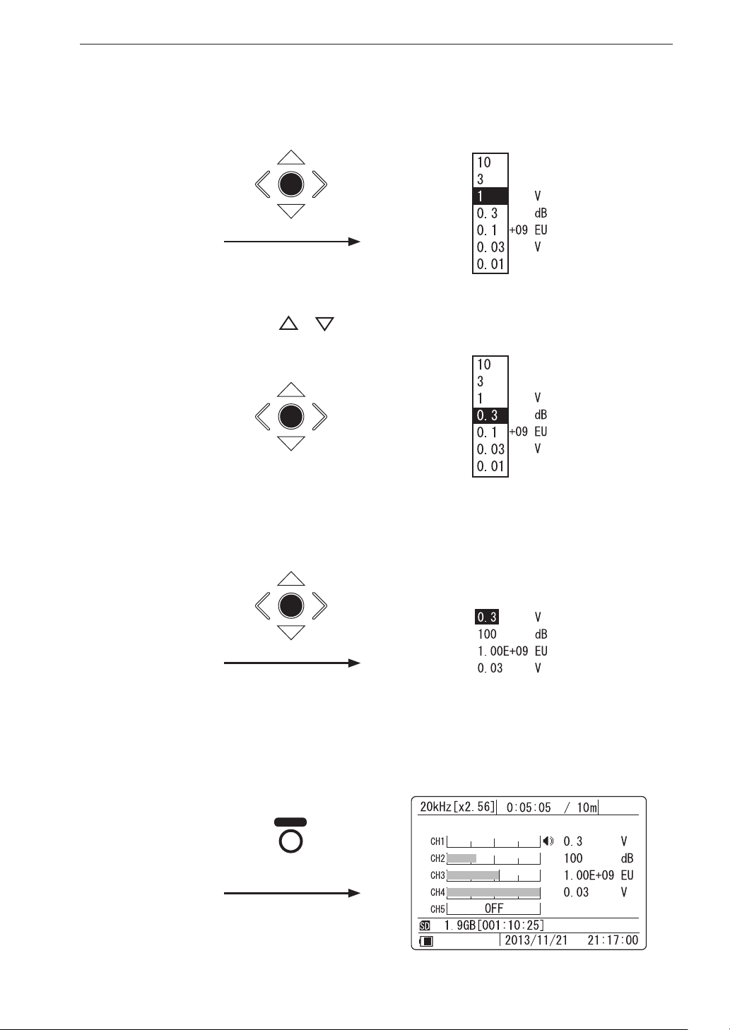
3. Activate the range change mode.
Press the [ENT] key to bring up the sub menu.
ENT
4. Select the new input range setting.
Preparations
Use the [
]/[ ] keys to change the input range.
ENT
5. Con rm the new input range setting.
Press the [ENT] key to return to the condition of step 2.
ENT
6. If you want to change the input range for another channel, repeat
the procedure from step 2. Otherwise press the [RANGE] key to
complete the range setting procedure.
RANGE
71
Page 84
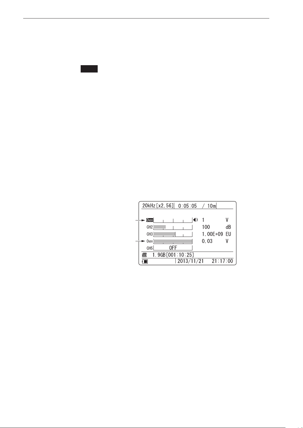
Preparations
Input range setting and overload
When setting the input range, check whether overload occurs. When this
happens, the overload indicator on the front panel lights up in red, and the
indication
OVER
appears on the display.
To improve reliability and ensure that overload does not occur for an extended
period, the overload history indication is convenient. This indication comes
on when there has been an overload event at any time within a given period.
To reset the indication, hold down the [CLEAR Ov] key. When the key is
released, overload history monitoring
OVER
begins, allowing the operator to
determine later whether there has been overload without having to constantly
check the overload indicator.
The overload history is also cleared when you make a recording parameter
setting. For details on clearing the overload history, see page 24 (Overload
Information).
Overload indication
Overload history indication
72
Page 85

Sampling
The sampling action of the DA-21 is controlled by the frequency range and
sampling frequency setting. The sampling frequency can be set to 2.4 times
or 2.56 times the frequency range.
Setting the frequency range
The frequency range can be set in six steps (100 Hz, 500 Hz, 1 kHz, 5 kHz,
10 kHz, 20 kHz). Make the setting using the “Frequency Range” item in
<Rec.Parameters> menu.
The frequency range value represents the highest effective frequency that
will be included in the recorded waveform. Higher components will be cut
off. When making the setting, choose a value that is higher than the highest
frequency of components that need to be included in the recorded data.
Preparations
Setting the sampling frequency
Waveform sampling is carried out at a frequency that is 2.4 times or 2.56
times the frequency range value. Make the setting using the “Sampling Fre-
quency” item in <Rec.Parameters> menu.
To perform FFT analysis after recording, using the ×2.56 setting is recom-
mended.
73
Page 86
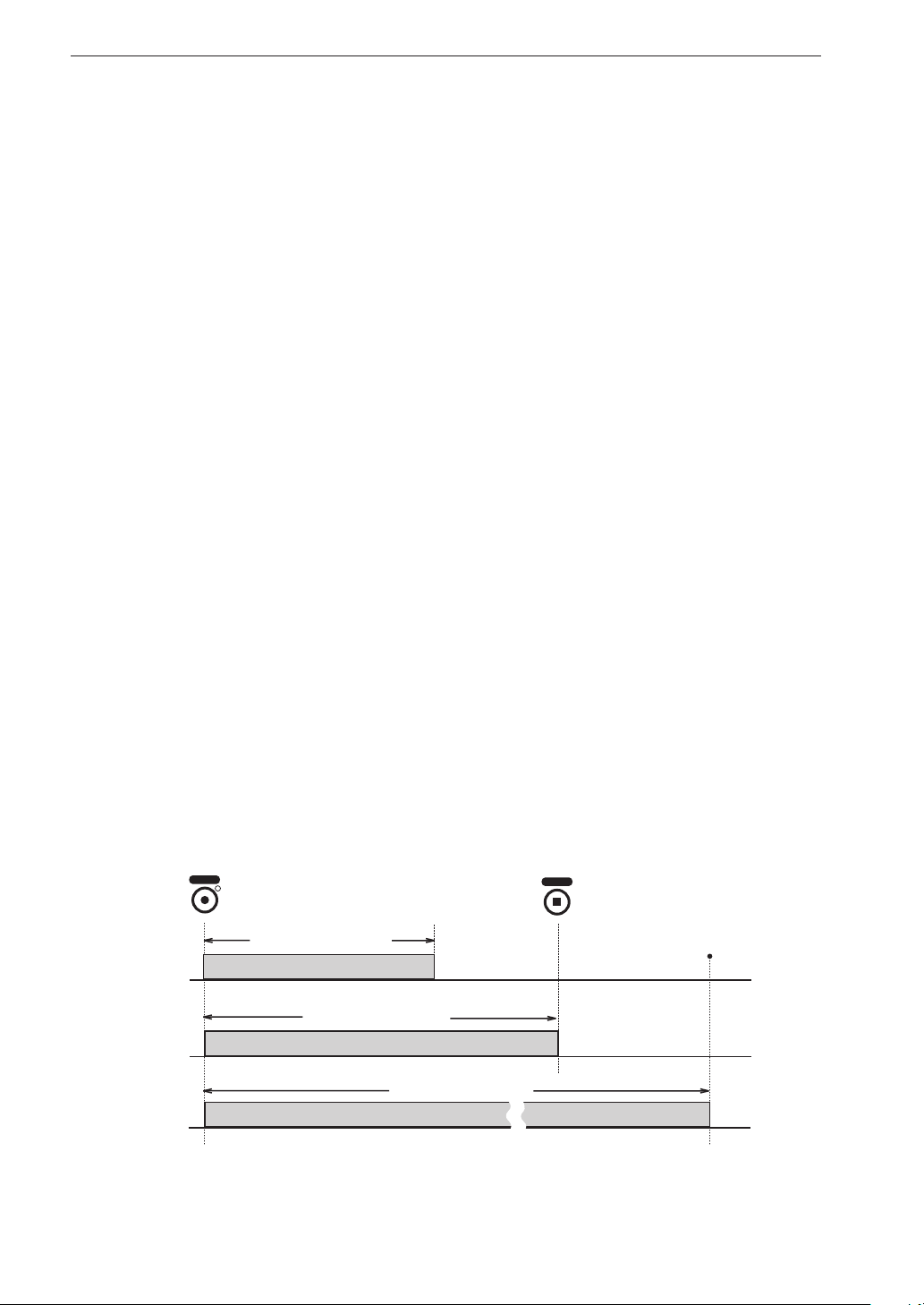
Preparations
Recording process
When you press the [REC] key, the data recording operation starts. Howev-
er, if the trigger function (described later) is used, recording may not begin
right away. In such a case, actual recording will only start when the trigger
conditions are met, or in other words when a trigger event occurs.
Recording stops when the amount of data corresponding to the recording time
has been recorded. If repeat trigger is selected, the recording condition is not
terminated at this point. Rather, the unit goes into trigger standby mode and
recording begins again at the next trigger event.
Even before the amount of data corresponding to the recording time has
been recorded, recording can be stopped by pressing the [STOP] key. It will
also stop when the SD memory card becomes full. Data recorded up to that
point will be stored.
Setting the recording time
The recording time can be set to 1 s to 59 s (seconds), 1 m to 59 m (minutes),
1 h to 24 h (hours), and a “Manual” setting is also available. When “Manual”
is selected, recording continues until the [STOP] key is pressed. Regardless
of the recording t i me setting, when there is no more room on the SD memory
card to store data (remaining recording time is about 10 seconds), recording
stops. Recording to one le is also limited to a maximum of 1000 hours.
When this limit is reached, the le is closed.
REC
Recording time
1 to 24 h
1 to 59 m
1 to 59 s
Manual
Manual
Recording procedure
Data recording in progress
Recording procedure
Data recording in progress
Data recording in progress
Recording procedure
STOP
Recording stops when SD
memory card becomes full or
when file length has reached
1000 h (hours).
(also at settings other than
Manual).
74
Page 87

Preparations
Make the recording time setting using the “Recording Time” item in <Rec.
Parameters> menu.
When the “Pre Recording Time” has been set to 1 second, the recording
time can be set to a value of 2 seconds or higher. When the “Pre Recording
Time” has been set to 5 seconds, the recording time can be set to a value of
6 seconds or higher.
The recording time setting cannot exceed the remaining available capacity
of the SD memory card inserted in the DA-21. If this applies, the recording
time will automatically be changed to the maximum available time when the
[ENT] key is pressed.
75
Page 88
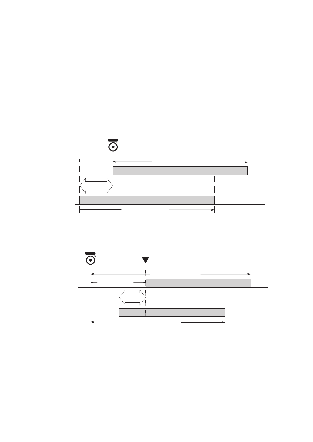
Preparations
Setting the Pre Recording Time
If you wish to include data from a point slightly before the [REC] key was
pressed or before the trigger event, use the Pre Recording Time function.
Available pre-recording settings are 0, 1, and 5 seconds.
The overall recorded data length will correspond to the recording time. The
Pre Recording Time is not added to the recording time, rather it is included
in the total.
Make the Pre Recording Time setting using the “Pre Recording Time” item
in <Rec.Parameters> menu (page 45).
REC
PreRec. Time
= 0 s
PreRec. Time
= 5 s
Pre Recording
Time
Data recording in progress
Recording procedure
Recording procedure
Data recording in progress
Difference in recording procedure with Pre Recording Time
(Pre Recording Time: 5 s, Recording Time: other than Manual, Trigger Mode: Free)
PreRec. Time
= 0 s
PreRec. Time
= 5 s
REC
Trigger standby
Trigger event
Recording procedure
Pre Recording
Time
Data recording in progress
Recording procedure
Data recording in progress
Difference in trigger operation depending on Pre Recording Time setting
(Pre Recording Time: 5 s, Recording Time: other than Manual, Trigger Mode: Single)
76
When the “Typ e” item of <Tr igger> menu is set to “Time”, the Pre Record i ng
Time setting has no effect.
Page 89

Preparations
Trigger co ndi ti ons
The trigger operation is determined by the trigger mode and trigger type.
When the trigger type is set to “Level”, the trigger level and trigger channel
must be set. For the “Time” trigger the start/stop time and interval must be
set. Only trigger events that occur while the DA-21 is in the trigger standby
condition are valid. Any trigger events that occur while data recording is in
progress are disregarded.
Setting the trigger mode
This setting determines the basic trigger operation.
Make the trigger mode setting using the “Mode” item in <Trigger> menu.
If the trigger function is not required, select the “Free” setting.
Free (trigger off)
Recording starts immediately when the [REC] key is pressed and
ends when the amount of data corresponding to the recording
time has been recorded.
Single (single trigger)
The unit goes into trigger standby mode when the [REC] key
is pressed. When a trigger event occurs, recording starts. When
the amount of data corresponding to the recording time has been
recorded, recording stops.
Repeat (repeat trigger)
The unit goes into trigger standby mode when the [REC] key
is pressed. When a trigger event occurs, recording starts. When
the amount of data corresponding to the recording time has been
recorded, the unit again goes into trigger standby mode and the
operation is repeated.
Note
Repeat setting is possible also when the Recording
Time is set to Manual. But the trigger operation is
carried out only once.
77
Page 90
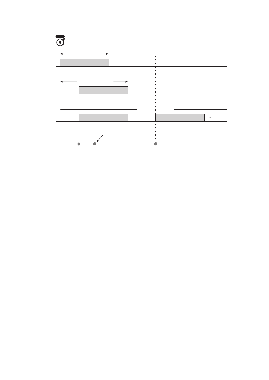
Preparations
REC
Recording procedure
Free
Single
Repeat
Trigger events
Data recording in progress
Recording procedure
Trigger
standby
Trigger
standby
Data recording in progress
Data recording in progress Data recording in progress
Recording procedure
Trigger
standby
During data recording,
trigger event is disregarded.
Difference in recording procedure according to trigger mode
(Pre Recording Time: 0, Recording Time: other than Manual, Trigger Type: Level or External)
78
Page 91

Setting the trigger type
This setting determines the type of event that serves as a trigger.
Make the setting using the “Type” item in <Trigger> menu.
Level (level trigger)
A trigger event occurs when the level of the input signal in the
speci ed trigger channel becomes equal or higher than a preset
threshold value (trigger level).
Note
• Delay of the record start time which recognized
by the AC input signal when the trigger type is
“Level”
If the input signal reaches a trigger level, recording
will be started from the point of time. However,
with the cause of data processing of DA-21, the
recording is started later than the time which ful lled trigger conditions.
If you want to record all the waveforms which
ful lled trigger conditions, set the “Pre Recording
Time” in <Rec.Parameters> menu as 1 second or
5 seconds.
Preparations
External (external trigger)
A trigger event occurs when the state of the Ext. Trig. connector
changes from H (open) to L (shorted). Detection is carried out
on the falling edge.
External Gate (external gate trigger)
Data recording is carried out while the state of the Ext. Trig.
connector is L (shorted). Also after the state changes to H (open),
recording continues for ve seconds (post-recording). If the state
of the Ext. Trig. connector is already L (shorted) when the [REC]
key is pressed, recording starts straight away because the trigger
conditions are met. With this trigger type, the recording time
setting has no effect.
79
Page 92
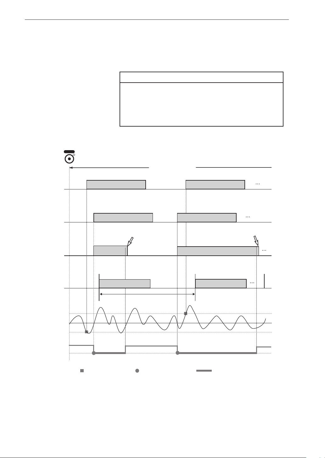
Preparations
Time
Recording is carried out from the speci ed Start Time to the spec-
i ed Stop Time, at intervals as speci ed by the Interval setting.
Note
The “Pre Recording Time” setting in <Rec.Parameters> menu has no effect. When the Stop Time is
reached, recording will stop, also if the Recording
Time is not yet completed.
REC
Recording procedure
Level
External
External
Gate
Time
Trigger channel
waveform
Ext. Trig.
connector signal
Trigger
standby
Trigger
standby
Trigger
standby
Trigger
standby
Data recording in progress Data recording in progress
Data recording in progress
5 seconds after state
changed from L to H
Data recording
in progress
Start time
Data recording in progress
Interval
Trigger
standby
Trigger
standby
Trigger
standby
Trigger
standby
Data recording in progress
5 seconds after state
changed from L to H
Data recording in progress
Data recording in progress
Stop time
Trigger level
Trigger level
Level trigger event
External trigger event
Ext. Trig. connectors
shorted
Difference in recording procedure according to trigger type
(Pre Recording Time: 0, Recording Time: other than Manual, Trigger Mode: Repeat)
80
Page 93

Preparations
Setting the trigger level
When the trigger type is set to “Level” (level of signal at input connector),
the actual level to be used as a trigger level must be set as a percentage
[%] of the full-scale value of the current input range.
Make the setting using the “Level” item in <Trigger> menu. The actual
trigger level is indicated on the bar graph for the trigger channel (see
page 26).
Setting the trigger channel
When the trigger type is set to “Level”, the channel to be used as trigger
channel must be set.
Make the setting using the “Ch” item in <Trigger> menu.
The indication “TRG” is shown at the left of the trigger channel. (For
information on level trigger target channel indication, see page 24).
Setting the start and stop time
When the trigger type is set to “Time”, set the start time and stop time
as follows.
Make the setting using the “Start Time” and “Stop Time” items in <Trigger>.
Note
When the start time setting is before the current time,
the setting automatically becomes “current time +
5 minutes”. When the stop time setting is before
the current time, the setting automatically becomes
“Start Time + 24 hours”.
81
Page 94
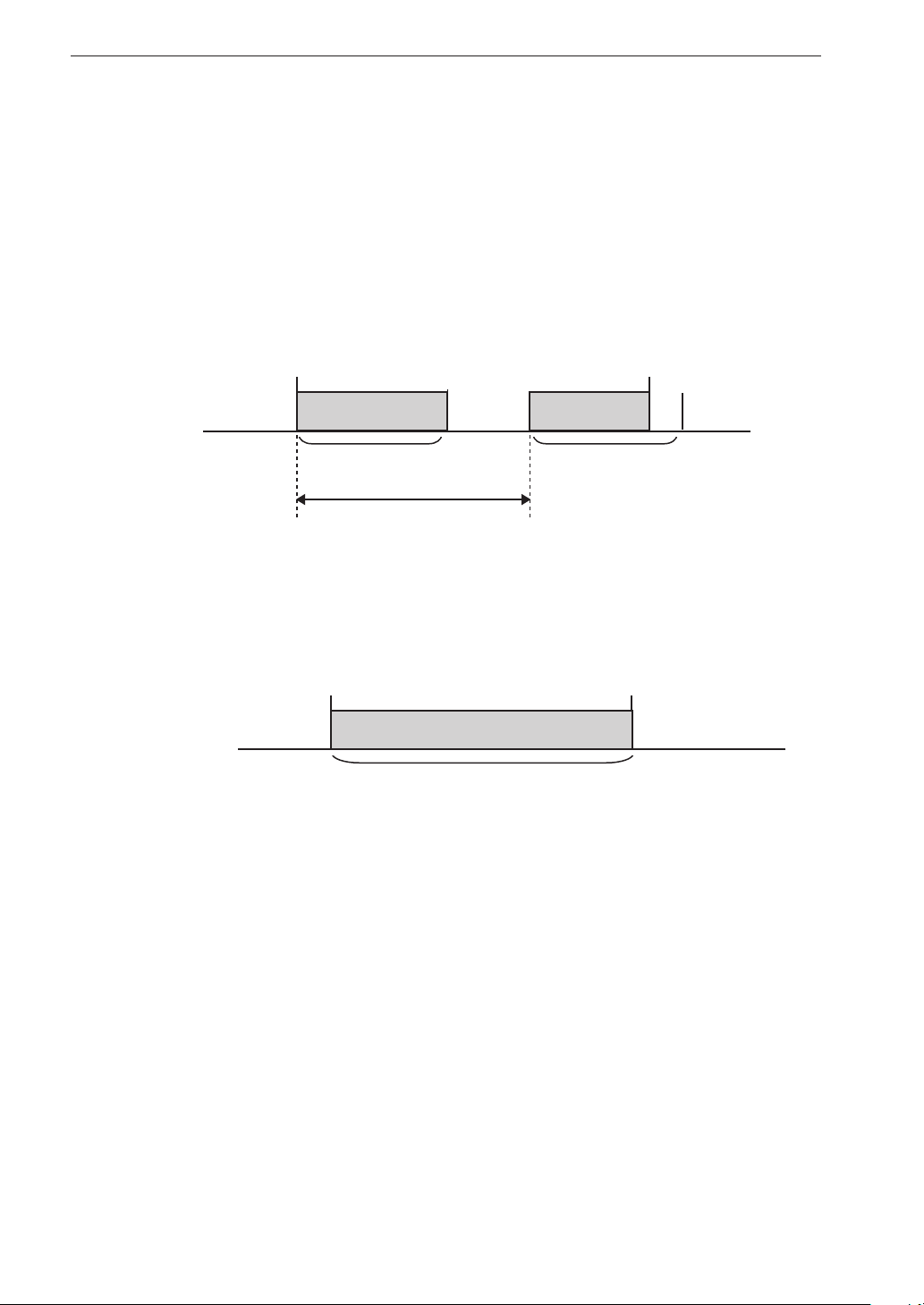
Preparations
Setting the recording interval
When the trigger mode is set to “Repeat” and the trigger type is set to
“Time”, set the interval as follows.
The interval setting cannot be shorter than the Recording Time setting.
Make the setting using the “Interval” item in <Trigger> menu.
When Stop Time is reached before Recording Time is up
Stop TimeStart Time
Data recording
in progress
Recording Time
(1 s to 24 h)
Interval
Data recording
in progress
Recording Time
(1 s to 24 h)
Recording stops (Stop Time has priority)
When Recording Time is set to Manual, recording stops at the Stop Time
Stop TimeStart Time
Data recording
in progress
Recording Time: Manual
Recording begins at the speci ed start date/time and ends at the spec-
i ed stop date/time.
82
Page 95
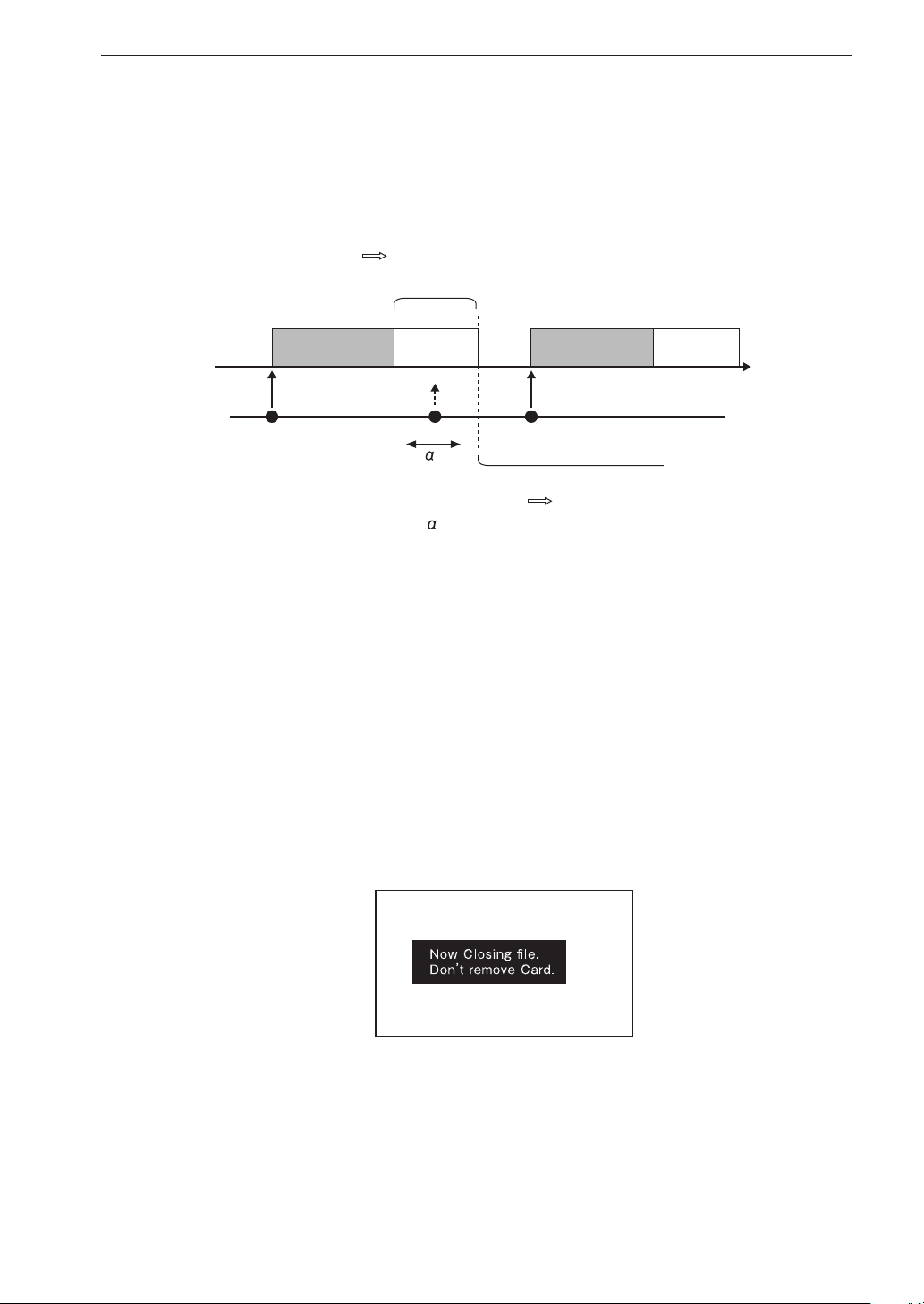
Preparations
Repeat trigger precaution
If trigger conditions are met while a le is being closed, the next recording
will not start.
Trigger event occurs during file save
Disregarded
(recording does not start)
rigger event
File write time
Recorded data are also written sequentially to a le during the recording
process, but at the point where recording stops, there will be a certain
amount of data that still need to be written. In addition, le management
information to allow later retrieval of the le also needs to be created.
The “File is being written” message refers to this process of writing re-
maining data and le management information. The following message
appears on the display during the process (see page 125).
Data recording
in progress
File is
being written
Trigger event occurs after file save is completed
" " is the time required to write previous data to SD memory
card as a file.
Data recording
in progress
Recording starts
File is
being written
Time
83
Page 96

Preparations
Auxiliary function setup
Device index number (<System> menu: Index)
The index number setting has no in uence on performance or functions of
the unit. Setting an index number is optional. The setting range is 1 to 255.
Some possible uses for the index number capability are listed below.
1. Temporary management (classi cation) of recorded data
Example 1 In a system where several DA-21 units are used, the
index number can serve to manage data according to
the unit on which the data were recorded.
Example 2 Manage recorded data according to measurement
purpose, measurement location, or similar.
Example 3 Manage recorded data according to measurement
parameters.
2. Using the index number as input range information
When using a system where a calibration signal is recorded in order
to calibrate recorded data, sensor range information will be required.
Using an input range value as the index number will facilitate data
management.
Example Set the index number to 120 when a sound level meter
is calibrated in input range 120 dB.
84
Page 97

Voice memo/marker
The voice memo function allows the operator to add comments before and
after the recording procedure or during recording. The marker function can
be used to mark a certain position, for example when a particular phenom-
enon occurred during recording. This makes it easy to later locate the data
for that point. For example, if noise was encountered at a certain point, the
marker can serve to locate and isolate the corresponding data.
Voice memo
While voice memo is activated, the sound picked up by the voice memo
microphone connected to the Voice Input connector can be recorded. When
the “Inp” item for CH5 in the <Input> menu is set to “Voice Memo”, the
indication appears to the right of the bar graph.
The level of the voice signal is shown by the bar graph for channel 5. Pressing
Preparations
the switch on the voice memo microphone activates voice memo recording.
Releasing the switch stops voice memo recording.
Marker
The marker function is only available during data recording. The maximum
number of marker points that can be set between the beginning and the end
of data recording is about 3,000.
When the “Inp” item for CH5 in the <Input> menu is set to “Marker”, the
indication appears to the right of the bar graph.
When the microphone switch is pressed, the indication ashes for one
second.
The marker precision is about 1 second.
85
Page 98
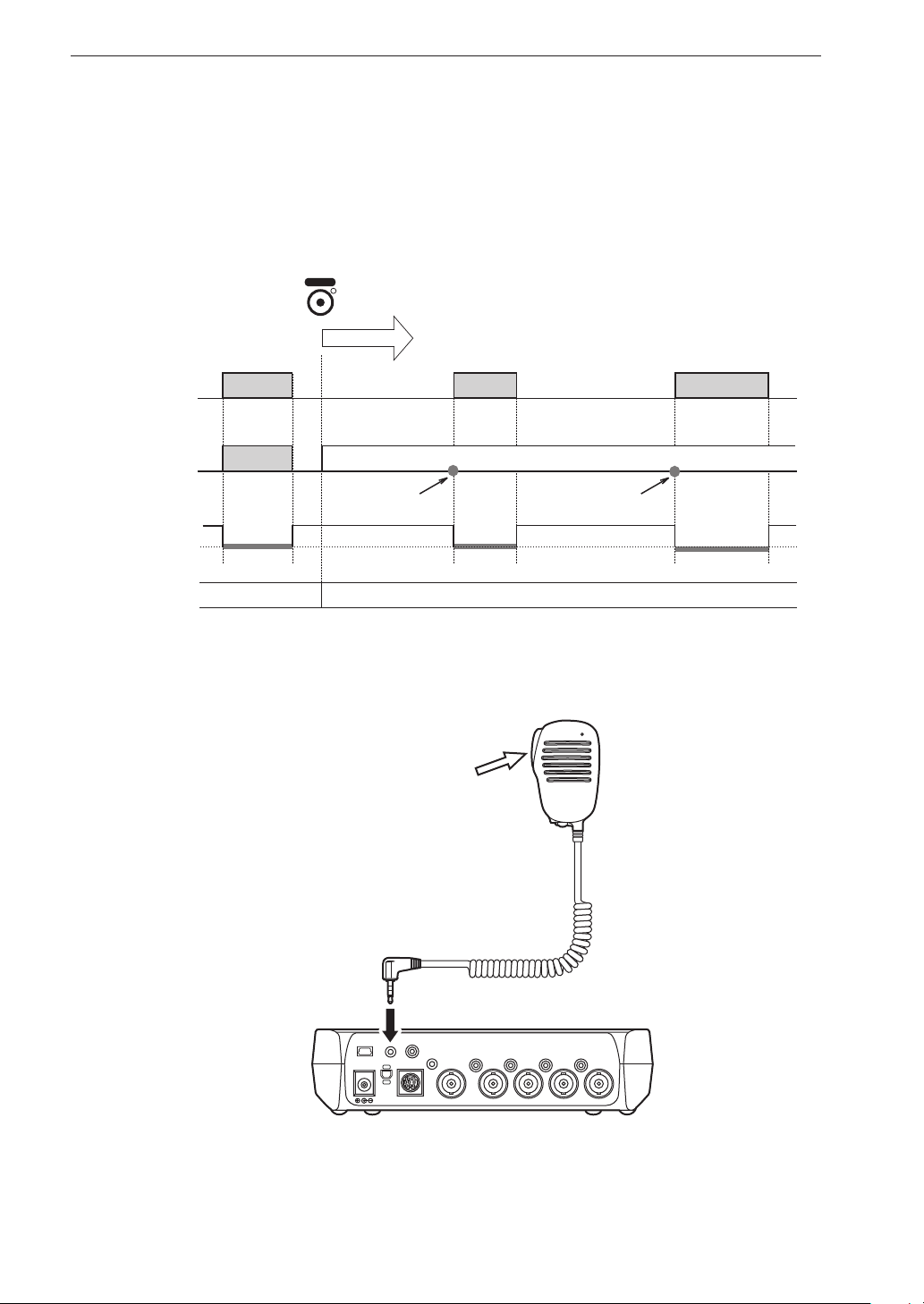
Preparations
Comparison of voice memo and marker operation
The diagram below illustrates the operation principle of the voice memo
and marker function. The functions differ in the action that occurs when the
microphone switch is pressed.
REC
Recording start
Voice Memo
Marker
Microphone
switch status
Voice memo before recording Voice memo or marker (according to setting) after recording start
Released
Pressed
Voice memo Voice memo
Voice memo
Marker is set
for this time point
Voice memo
Input signal
Marker is set
for this time point
Voice memo microphone
MIC
Microphone switch
86
To Voice Input
connector
USB
DC IN 5-20V
Voice
Input
Sync.
Remote Controller
Ext. Trig.
Monitor
Out
Tacho
4
3
Output
2
1
Input
Page 99
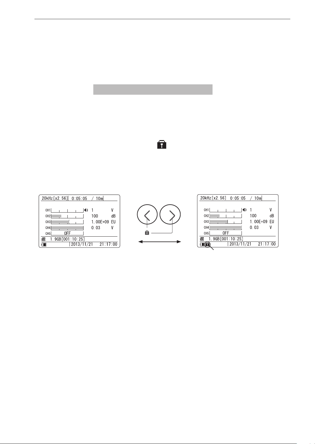
Preparations
Preventing inadvertent operation (key lock and menu lock)
This section explains the key lock and menu lock functions that serve to
prevent operation errors when performing data recording in the eld.
Key lock Makes almost all keys inactive
Pressing and holding the [<] and [>] keys together for a few seconds activates
the key lock condition. In this condition, all keys except the [LIGHT] key
and the [<]/[>] keys are locked. Remote control operation remains possible.
To cancel the key lock state, press and hold the [<] and [>] keys once more.
During key lock, a key lock icon [ ] appears in the bottom left of the display.
Key lock activated
Hold down for 2 seconds
Indicates the key lock condition
87
Page 100
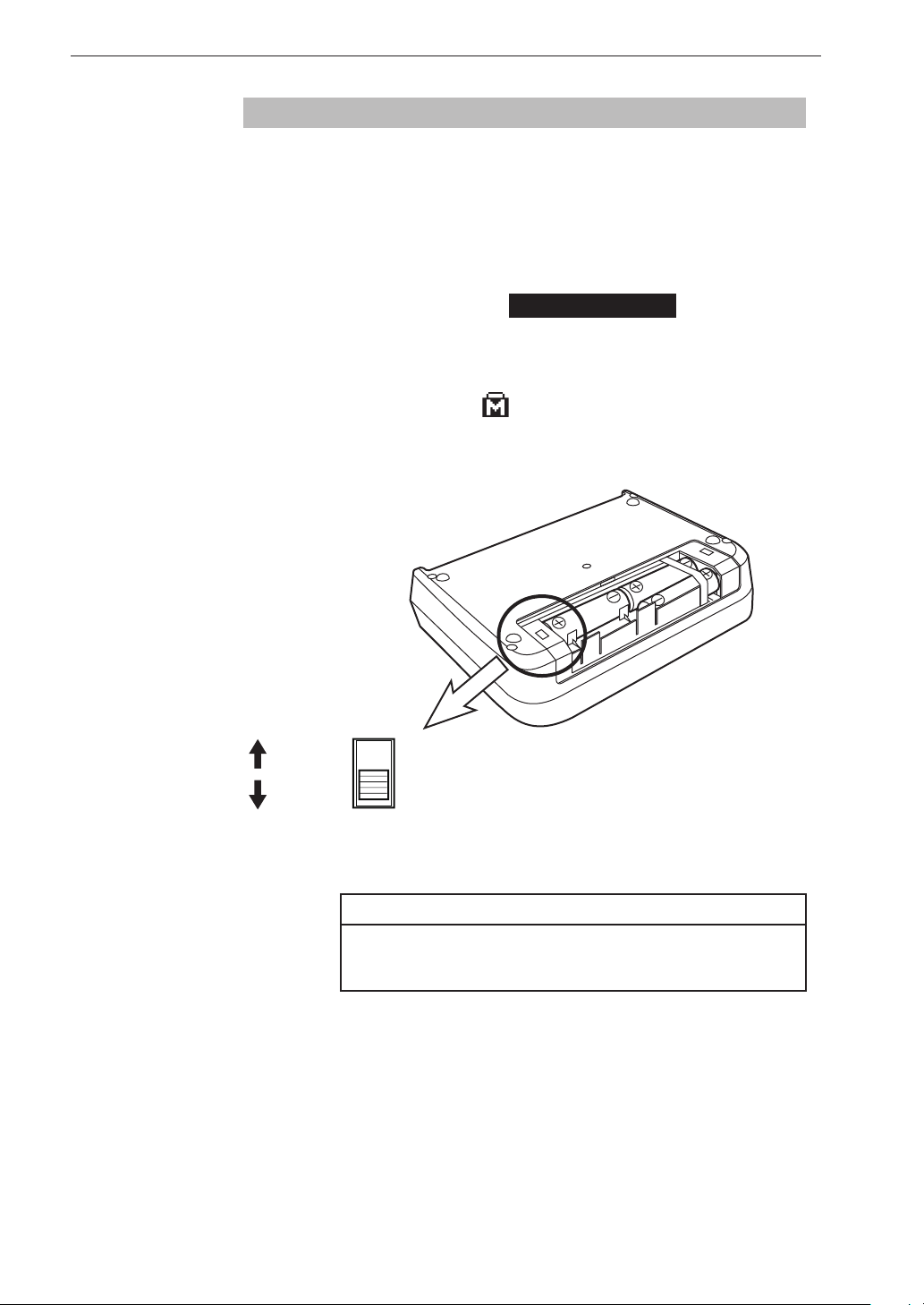
Preparations
Menu lock Changing menu settings and deleting data are disabled
Opening the battery compartment cover gives access to a slide [MENU]
switch in the lower left section, as shown in the illustration below. When you
set this switch to the LOCK position, menu settings cannot be changed, and
data in recall mode cannot be deleted. Only the input range setting can still
be changed. This condition is called the menu lock mode.
When menu lock is active, the indication
call up a menu and attempt to make a setting, or if you attempt to delete data
in recall mode.
During menu lock, a menu lock icon [
display.
MENU LOCKED
] appears in the bottom left of the
appears if you
MENU
Menu lock mode
Normal menu
operation
LOCK
UNLOCK
88
Note
Operate the [MENU] switch only while power to
the unit is switched off.
 Loading...